US5013122A - Threaded crimping body for fiber optic termination - Google Patents
Threaded crimping body for fiber optic terminationDownload PDFInfo
- Publication number
- US5013122A US5013122AUS07/429,676US42967689AUS5013122AUS 5013122 AUS5013122 AUS 5013122AUS 42967689 AUS42967689 AUS 42967689AUS 5013122 AUS5013122 AUS 5013122A
- Authority
- US
- United States
- Prior art keywords
- directed threads
- fiber
- termination
- buffer
- crimping
- Prior art date
- Legal status (The legal status is an assumption and is not a legal conclusion. Google has not performed a legal analysis and makes no representation as to the accuracy of the status listed.)
- Expired - Fee Related
Links
- 238000002788crimpingMethods0.000titleclaimsabstractdescription53
- 239000000835fiberSubstances0.000titleclaimsabstractdescription38
- 239000013307optical fiberSubstances0.000claimsabstractdescription23
- 230000003287optical effectEffects0.000claimsabstractdescription10
- 239000000463materialSubstances0.000claimsdescription6
- 239000013013elastic materialSubstances0.000abstract1
- 239000000853adhesiveSubstances0.000description2
- 230000001070adhesive effectEffects0.000description2
- 230000006835compressionEffects0.000description2
- 238000007906compressionMethods0.000description2
- 230000013011matingEffects0.000description2
- 229910001369BrassInorganic materials0.000description1
- 230000002411adverseEffects0.000description1
- 238000013019agitationMethods0.000description1
- 239000010951brassSubstances0.000description1
- 238000010276constructionMethods0.000description1
- 238000010438heat treatmentMethods0.000description1
- 230000037431insertionEffects0.000description1
- 238000003780insertionMethods0.000description1
- 238000004519manufacturing processMethods0.000description1
- 239000007769metal materialSubstances0.000description1
- 238000009417prefabricationMethods0.000description1
- 229920001169thermoplasticPolymers0.000description1
- 239000004416thermosoftening plasticSubstances0.000description1
Images


Classifications
- G—PHYSICS
- G02—OPTICS
- G02B—OPTICAL ELEMENTS, SYSTEMS OR APPARATUS
- G02B6/00—Light guides; Structural details of arrangements comprising light guides and other optical elements, e.g. couplings
- G02B6/24—Coupling light guides
- G02B6/36—Mechanical coupling means
- G02B6/38—Mechanical coupling means having fibre to fibre mating means
- G02B6/3807—Dismountable connectors, i.e. comprising plugs
- G02B6/3833—Details of mounting fibres in ferrules; Assembly methods; Manufacture
- G02B6/3855—Details of mounting fibres in ferrules; Assembly methods; Manufacture characterised by the method of anchoring or fixing the fibre within the ferrule
- G02B6/3857—Crimping, i.e. involving plastic deformation
- G—PHYSICS
- G02—OPTICS
- G02B—OPTICAL ELEMENTS, SYSTEMS OR APPARATUS
- G02B6/00—Light guides; Structural details of arrangements comprising light guides and other optical elements, e.g. couplings
- G02B6/24—Coupling light guides
- G02B6/36—Mechanical coupling means
- G02B6/38—Mechanical coupling means having fibre to fibre mating means
- G02B6/3807—Dismountable connectors, i.e. comprising plugs
- G02B6/3833—Details of mounting fibres in ferrules; Assembly methods; Manufacture
- G02B6/3855—Details of mounting fibres in ferrules; Assembly methods; Manufacture characterised by the method of anchoring or fixing the fibre within the ferrule
- G—PHYSICS
- G02—OPTICS
- G02B—OPTICAL ELEMENTS, SYSTEMS OR APPARATUS
- G02B6/00—Light guides; Structural details of arrangements comprising light guides and other optical elements, e.g. couplings
- G02B6/24—Coupling light guides
- G02B6/36—Mechanical coupling means
- G02B6/38—Mechanical coupling means having fibre to fibre mating means
- G02B6/3807—Dismountable connectors, i.e. comprising plugs
- G02B6/3887—Anchoring optical cables to connector housings, e.g. strain relief features
- G02B6/3888—Protection from over-extension or over-compression
Definitions
- the present inventionis a termination for optical members comprising an alignment ferrule and an optical fiber member.
- the optical fiber memberhas a flexible buffer and fiber.
- the alignment ferrulehas tubular passageway for encircling the optical member and comprises an elongated sleeve body and a tip with centrally disposed aperture therethrough for closely receiving an end of the fiber from the tubular passageway.
- the terminationfurther comprises a crimping body of deformable material, intimately surrounding the flexible buffer and fiber and attached by crimping thereto and characterized by having outwardly directed threads for interconnection with threads of the alignment ferrule.
- a termination for optical memberscomprises a connector and an optical fiber member having flexible buffer and optical fiber
- the connectorcomprises an alignment ferrule having tubular passageway for encircling the flexible buffer and optical fiber, and a tip with centrally disposed aperture therethrough for closely receiving an end of the fiber from the tubular passageway and a crimping body of deformable material intimately surrounding the flexible buffer and fiber and attached by crimping thereto.
- the terminationis characterized in that the crimping body, together with the buffer and fiber, is engaged by compression fit within the tubular passageway and against the walls of the passageway of the alignment ferrule.
- Intimate crimping of the body to the optical memberpermits prefabrication at a manufacturing site, and transportation of the combined crimping body and optical member for connection as an integral piece at a connection location.
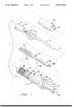
- FIG. 1is a fragmentary perspective view of the preferred embodiment of the termination for optical members.
- FIG. 2is an enlarged section view through the termination of FIG. 1.
- FIG. 4is an enlarged section view through the termination of FIG. 3.
- the cable 3is of known construction and includes a flexible buffer 4, concentrically encircling the fiber 2, multiple strands of strength members 5 extending axially of the buffer 4 and distributed around the periphery of the buffer 4, and an external jacket 6.
- Termination 7includes connector 1, optical fiber 2 and buffer 4, and crimping body 8.
- the connector 1consists of a single, unitary piece having two parts; a tip 9, and an elongated sleeve body 10.
- the tip 9has flange portion 11 and nose portion 12.
- the tip 9may be made of a hard, metal material, such as brass, or a deformable material, such as a thermoplastic.
- the tip 9has a profile through passage 13 with entry section 14 and truncated, conical surface 15 leading to exit passage 16.
- Profile axial bore 17is aligned with exit passage 16, leading to narrow exit bore 18 at front mating surface 19.
- the outside of the tip 9is profiled by key 20 and tapered surface 21 between flange 11 and nose 12.
- Elongated sleeve body 10has a through passage 22 extending through the body 10, and further, has flanges 23 and 24 at its rearward end, and barrel-shaped front 25 and rear 26 portions, with rear portion 26 having a knurled surface 27.
- ferrule 1is shown as a single piece, but may be a bipartite body consisting of a separate sleeve body 10 and tip 9 attached by threading the body together or connection by ultrasonics or heating or by adhesive or mechanical means.
- Crimping body 8is in the form of a sleeve with axial central passageway 28, and connection section 29, crimping section 30 and end 38.
- Connection section 29is characterized by outwardly directed threads 31 for engagement with inwardly directed threads 32 located at the internal entry portion 33 of the through passage 22 of ferrule 9 as hereinafter described.
- Crimping body 8is of a relatively soft, deformable material which may be compressed or pinched by means of a crimping or swaging tool into intimate contact with the buffer 4 of the optical fiber cable 3.
- Sleeve 34has through passage 35 of a diameter so that it forms a close fit over the rear barrel section 26 of ferrule 1 at knurled surface 27 as hereinafter described.
- the present inventionis utilized with a standard optical fiber cable 3 by first preparing the cable 3 in known fashion to expose a section of the fiber buffer 4 and fiber 2.
- the fiber 2 and the buffer portion 4are passed through the axial central passageway 28 of the crimping body 8 from rear to front until fully inserted with the forward end of the buffer 4 and fiber 2 extending slightly beyond the forward end of the crimping body 8 with strength members 5 positioned outside the crimping body 8.
- a conventional crimping toolis positioned onto the crimping body 8 at crimping section 30 and the tool controllably operated to crimp section 30 onto the buffer 4 of the stripped fiber cable.
- the resulting assembly of buffer 4 and fiber 2 and crimping body 8is then inserted into ferrule 1 from rear 26 to the front 25 until the assembly of buffer 4, fiber 2 and crimping body 8 begins to enter central passageway 13 within nose portion 11 and outwardly directed threads 31 of connection section 29 commence to engage with inwardly directed threads 32 at internal entry portion 33 of ferrule rear portion 26.
- strength members 5are distributed along the knurled surface 27 of rear portion 26.
- the fiber 2passes through passage 22 and exit bore 18 of tip 9 to extend through and beyond the face 19 of the tip 9.
- the forward end of the buffer 4 and fiber 2extend slightly beyond the end 38 of the crimping body 8.
- sleeve 34is fitted axially around ferrule 1 at knurled surface 27 entrapping strength members 5 of crimping body 8.
- Knurling 27provides increased friction to retain the sleeve 34 in place as a compression fit around ferrule 1 to further secure strength members 5.
- the body 8 and buffer 4 and fiber 2is prevented from backing out of ferrule 1.
- the termination 7is insulated from down line agitation which would adversely affect the connection of the fiber 2 at the face 19 of tip 9.
- FIGS. 3 and 4is shown another embodiment of the present invention wherein the crimping body 8 is attached to ferrule tip 9.
- like itemsare identified by the same numbers as in FIGS. 1 and 2.
- Crimping body 8is an elongated sleeve body having three sections--a nose section 36, a central elongated crimping section 37, and a rear section 43. Crimping body 8 also is characterized by through passage 39 extending through and along the longitudinal axis of crimping body 8. Nose section 36 includes crimping tip 38 which, during assembly, acts as a guide for inserted buffer 4 and cable 2 as hereinafter described. The crimping body 8 has a profile through passage 39 with entry section 40, exit passage 41 and outwardly directed threads 42.
- Central crimping section 37is of an elongated shape with through passage 39 and rear section 43 characterized by knurled surface 44. Tip 9 is as described with reference to FIGS. 1 and 2 but additionally having inwardly directed threads 45 at entry section 14 for connection with threads 42 as hereinafter described.
- FIGS. 3 and 4is utilized with a standard optical fiber cable 3 by first preparing the cable 3 in known fashion to expose a section of the fiber buffer 4 and fiber 2.
- the fiber 2 and the buffer portion 4are passed through the axial passageway 39 of the crimping body from rear to front until fully inserted through the passage 39 and out the exit passage 41 of the tip 38 of the crimping body 8 with strength members 5 positioned outside the crimping body 8 immediately around the knurled rear section 44.
- a conventional crimping toolis positioned onto the crimping body at crimping section 38 and the tool controllably operated to crimp this section onto the buffer 4 of the stripped fiber cable.
- This assembly of buffer 4 and fiber 2 and crimping body 8is then inserted into the profile through passage of tip 9 at entry section 13 until crimp tip 38 rests within tip 9 and outwardly directed threads 42 begin to engage with the inwardly directed threads 45 of ferrule tip 9.
- the combination of buffer 4, fiber 2 and crimping body 8is then threaded onto tip 9 until fiber 2 extends through the through passageway 13 and through profile axial bore 17 and exit passage 16 and through narrow bore 18 to extend beyond front mating surface 19.
- sleeve 34is drawn toward the rear end of crimping body 8 until strength members 5 of the cable 3 are captured by the fit between sleeve 34 and knurling 44. The section between these surfaces retains the strength members and locks the cable 3 to further prevent the buffer 4 and fiber 2 from backing out of body 8.
Landscapes
- Physics & Mathematics (AREA)
- General Physics & Mathematics (AREA)
- Optics & Photonics (AREA)
- Mechanical Coupling Of Light Guides (AREA)
Abstract
Description
Claims (5)
Priority Applications (1)
| Application Number | Priority Date | Filing Date | Title |
|---|---|---|---|
| US07/429,676US5013122A (en) | 1989-08-29 | 1989-10-31 | Threaded crimping body for fiber optic termination |
Applications Claiming Priority (2)
| Application Number | Priority Date | Filing Date | Title |
|---|---|---|---|
| US07/400,303US4961624A (en) | 1989-08-29 | 1989-08-29 | Optical fiber termination with crimping body |
| US07/429,676US5013122A (en) | 1989-08-29 | 1989-10-31 | Threaded crimping body for fiber optic termination |
Related Parent Applications (1)
| Application Number | Title | Priority Date | Filing Date |
|---|---|---|---|
| US07/400,303Continuation-In-PartUS4961624A (en) | 1989-08-29 | 1989-08-29 | Optical fiber termination with crimping body |
Publications (1)
| Publication Number | Publication Date |
|---|---|
| US5013122Atrue US5013122A (en) | 1991-05-07 |
Family
ID=27016985
Family Applications (1)
| Application Number | Title | Priority Date | Filing Date |
|---|---|---|---|
| US07/429,676Expired - Fee RelatedUS5013122A (en) | 1989-08-29 | 1989-10-31 | Threaded crimping body for fiber optic termination |
Country Status (1)
| Country | Link |
|---|---|
| US (1) | US5013122A (en) |
Cited By (16)
| Publication number | Priority date | Publication date | Assignee | Title |
|---|---|---|---|---|
| US5265183A (en)* | 1992-07-02 | 1993-11-23 | Molex Incorporated | Fiber optic connector and tool for assembling same |
| US5307432A (en)* | 1992-10-09 | 1994-04-26 | Luxtec Corporation | Crimped light source terminations |
| US5317664A (en)* | 1992-12-15 | 1994-05-31 | Thomas & Betts Corporation | Fiber optic assembly and crimp sleeve used with the assembly |
| US5375183A (en)* | 1993-05-25 | 1994-12-20 | The Whitaker Corporation | Overmolded alignment ferrule |
| US5381500A (en)* | 1993-10-12 | 1995-01-10 | The Whitaker Corporation | Metal insert and buffer retention plunger |
| JPH08110438A (en)* | 1994-10-07 | 1996-04-30 | Seiko Giken:Kk | Optical fiber assembly |
| US5621835A (en)* | 1994-05-20 | 1997-04-15 | Seikoh Giken Co., Ltd. | Optical fiber assembly and manufacturing method for the same |
| EP0935148A3 (en)* | 1998-02-05 | 1999-09-22 | Lucent Technologies Inc. | Optical fiber connector with cable anchoring means |
| FR2819894A1 (en)* | 2001-01-25 | 2002-07-26 | Fci France | Fibre optic cable section connections having bayonet section with spring attached optical contact pushed/recess channel connector section held |
| US20050213893A1 (en)* | 2004-03-25 | 2005-09-29 | Hiroshi Hamasaki | Optical fiber connector and connecting method |
| US20100290746A1 (en)* | 2009-04-06 | 2010-11-18 | Adc Telecommunications, Inc. | Drop cable pass-thru fitting |
| USRE43542E1 (en) | 2000-06-12 | 2012-07-24 | Adc Gmbh | Assembly and method for use in terminating an optical fiber or fibers |
| US20130029511A1 (en)* | 2011-07-29 | 2013-01-31 | David Charles Van Den Berg | Cable system and methods of assembling a cable system |
| US20140126862A1 (en)* | 2012-11-02 | 2014-05-08 | Tyco Electronics Corporation | Terminus assembly for terminating an optical cable |
| US9036975B2 (en) | 2009-02-24 | 2015-05-19 | Adc Telecommunications, Inc. | Fiber optic cable pass-thru fitting |
| US9116310B2 (en) | 2009-03-06 | 2015-08-25 | Adc Telecommunications, Inc. | Fiber optic cable pass-thru fitting with a cable retention member for routing strength members |
Citations (13)
| Publication number | Priority date | Publication date | Assignee | Title |
|---|---|---|---|---|
| US3946467A (en)* | 1974-12-09 | 1976-03-30 | Northern Electric Company, Limited | Clamp for an optical fibre |
| US4148557A (en)* | 1977-07-11 | 1979-04-10 | Hewlett-Packard Company | Adjustable fiber optic connector |
| US4198119A (en)* | 1978-09-13 | 1980-04-15 | International Business Machines Corporation | Connector for optical cable |
| US4355862A (en)* | 1979-09-01 | 1982-10-26 | Amp Incorporated | Optical fibre termination |
| US4362356A (en)* | 1978-09-11 | 1982-12-07 | Amp Incorporated | Concentric optic termination utilizing a fixture |
| US4368948A (en)* | 1978-11-13 | 1983-01-18 | Radiall | Optical fiber connector and method |
| US4406515A (en)* | 1981-07-14 | 1983-09-27 | Augat Inc. | Fiber optic connector |
| US4440469A (en)* | 1980-09-18 | 1984-04-03 | Amp Incorporated | Optical waveguide connector |
| US4607911A (en)* | 1983-10-03 | 1986-08-26 | Conax Buffalo Corporation | Connector for an optical fiber having a stationary clamp engaged and operated by a rotatable member |
| US4674833A (en)* | 1984-09-18 | 1987-06-23 | Leetec Limited | Connectors for optical fibres |
| US4679895A (en)* | 1984-08-31 | 1987-07-14 | Amp Incorporated | Adhesiveless optical fiber connector |
| US4695124A (en)* | 1984-01-30 | 1987-09-22 | The Furukawa Electric Co., Ltd. | Plastic optical fiber cable with ferrule |
| US4773725A (en)* | 1982-05-24 | 1988-09-27 | Amp Incorporated | Termination of a fiber optic transmission member and method therefore |
- 1989
- 1989-10-31USUS07/429,676patent/US5013122A/ennot_activeExpired - Fee Related
Patent Citations (13)
| Publication number | Priority date | Publication date | Assignee | Title |
|---|---|---|---|---|
| US3946467A (en)* | 1974-12-09 | 1976-03-30 | Northern Electric Company, Limited | Clamp for an optical fibre |
| US4148557A (en)* | 1977-07-11 | 1979-04-10 | Hewlett-Packard Company | Adjustable fiber optic connector |
| US4362356A (en)* | 1978-09-11 | 1982-12-07 | Amp Incorporated | Concentric optic termination utilizing a fixture |
| US4198119A (en)* | 1978-09-13 | 1980-04-15 | International Business Machines Corporation | Connector for optical cable |
| US4368948A (en)* | 1978-11-13 | 1983-01-18 | Radiall | Optical fiber connector and method |
| US4355862A (en)* | 1979-09-01 | 1982-10-26 | Amp Incorporated | Optical fibre termination |
| US4440469A (en)* | 1980-09-18 | 1984-04-03 | Amp Incorporated | Optical waveguide connector |
| US4406515A (en)* | 1981-07-14 | 1983-09-27 | Augat Inc. | Fiber optic connector |
| US4773725A (en)* | 1982-05-24 | 1988-09-27 | Amp Incorporated | Termination of a fiber optic transmission member and method therefore |
| US4607911A (en)* | 1983-10-03 | 1986-08-26 | Conax Buffalo Corporation | Connector for an optical fiber having a stationary clamp engaged and operated by a rotatable member |
| US4695124A (en)* | 1984-01-30 | 1987-09-22 | The Furukawa Electric Co., Ltd. | Plastic optical fiber cable with ferrule |
| US4679895A (en)* | 1984-08-31 | 1987-07-14 | Amp Incorporated | Adhesiveless optical fiber connector |
| US4674833A (en)* | 1984-09-18 | 1987-06-23 | Leetec Limited | Connectors for optical fibres |
Cited By (23)
| Publication number | Priority date | Publication date | Assignee | Title |
|---|---|---|---|---|
| US5265183A (en)* | 1992-07-02 | 1993-11-23 | Molex Incorporated | Fiber optic connector and tool for assembling same |
| US5307432A (en)* | 1992-10-09 | 1994-04-26 | Luxtec Corporation | Crimped light source terminations |
| US5317664A (en)* | 1992-12-15 | 1994-05-31 | Thomas & Betts Corporation | Fiber optic assembly and crimp sleeve used with the assembly |
| US5375183A (en)* | 1993-05-25 | 1994-12-20 | The Whitaker Corporation | Overmolded alignment ferrule |
| US5381500A (en)* | 1993-10-12 | 1995-01-10 | The Whitaker Corporation | Metal insert and buffer retention plunger |
| US5621835A (en)* | 1994-05-20 | 1997-04-15 | Seikoh Giken Co., Ltd. | Optical fiber assembly and manufacturing method for the same |
| JPH08110438A (en)* | 1994-10-07 | 1996-04-30 | Seiko Giken:Kk | Optical fiber assembly |
| EP0935148A3 (en)* | 1998-02-05 | 1999-09-22 | Lucent Technologies Inc. | Optical fiber connector with cable anchoring means |
| USRE43542E1 (en) | 2000-06-12 | 2012-07-24 | Adc Gmbh | Assembly and method for use in terminating an optical fiber or fibers |
| EP1243954A3 (en)* | 2001-01-25 | 2004-07-28 | Fci | Easily mountable optical connector system |
| FR2819894A1 (en)* | 2001-01-25 | 2002-07-26 | Fci France | Fibre optic cable section connections having bayonet section with spring attached optical contact pushed/recess channel connector section held |
| CN100406941C (en)* | 2004-03-25 | 2008-07-30 | 株式会社东芝 | Fiber Optic Connectors and Connection Methods |
| US7314317B2 (en)* | 2004-03-25 | 2008-01-01 | Kabushiki Kaisha Toshiba | Optical fiber connector and connecting method |
| US20050213893A1 (en)* | 2004-03-25 | 2005-09-29 | Hiroshi Hamasaki | Optical fiber connector and connecting method |
| US9036975B2 (en) | 2009-02-24 | 2015-05-19 | Adc Telecommunications, Inc. | Fiber optic cable pass-thru fitting |
| US9116310B2 (en) | 2009-03-06 | 2015-08-25 | Adc Telecommunications, Inc. | Fiber optic cable pass-thru fitting with a cable retention member for routing strength members |
| US20100290746A1 (en)* | 2009-04-06 | 2010-11-18 | Adc Telecommunications, Inc. | Drop cable pass-thru fitting |
| WO2010117656A3 (en)* | 2009-04-06 | 2011-03-31 | Adc Telecommunications, Inc. | Drop cable pass-thru fitting |
| US20130029511A1 (en)* | 2011-07-29 | 2013-01-31 | David Charles Van Den Berg | Cable system and methods of assembling a cable system |
| US8523590B2 (en)* | 2011-07-29 | 2013-09-03 | General Electric Company | Cable system and methods of assembling a cable system |
| US20140126862A1 (en)* | 2012-11-02 | 2014-05-08 | Tyco Electronics Corporation | Terminus assembly for terminating an optical cable |
| CN104769469A (en)* | 2012-11-02 | 2015-07-08 | 泰科电子公司 | Terminal Assemblies for Terminating Fiber Optic Cables |
| US9256031B2 (en)* | 2012-11-02 | 2016-02-09 | Tyco Electronics Corporation | Terminus assembly for terminating an optical cable |
Similar Documents
| Publication | Publication Date | Title |
|---|---|---|
| US5013122A (en) | Threaded crimping body for fiber optic termination | |
| US4812006A (en) | Fiber optic connector with colley retention | |
| US4964685A (en) | Connector with precision fiber optic alignment clamp | |
| US5396572A (en) | Optical fiber connector having a unipartite cap | |
| US4961624A (en) | Optical fiber termination with crimping body | |
| US4679895A (en) | Adhesiveless optical fiber connector | |
| US4127319A (en) | Termination means for fiber optic bundle | |
| US5091990A (en) | Fiber-optic connector | |
| EP0979430B1 (en) | Fiber optic connector | |
| US4336977A (en) | Crimped connector assembly for fiber optic cables | |
| US5181267A (en) | Sheath connector for an optical cable | |
| US5123071A (en) | Overconnector assembly for a pair of push-pull coupling type optical fiber connectors | |
| US5094552A (en) | Interlocking strain relief | |
| US5418874A (en) | Force transfer system for an optical fiber connector | |
| US6422764B1 (en) | Clamping mechanism for an optical fiber | |
| US4447120A (en) | Fiber optic cable clamp | |
| US5732175A (en) | Connecting system for fiber optic termination | |
| US9395500B2 (en) | Optical fiber connector and cable assembly with dual diameter crimp sleeve | |
| EP0061243B1 (en) | Optical waveguide connector | |
| US4795231A (en) | Optical fiber connector | |
| US5140662A (en) | Method of assembling connector and cable | |
| JPH0682657A (en) | Optical fiber cable and common male/female connector for optical fiber | |
| US4815808A (en) | Optical fiber cable fixing mechanism in plug | |
| US5155900A (en) | Hand tool for assembling a fiber optic connector | |
| US5425119A (en) | Connector strain relief for optical fiber |
Legal Events
| Date | Code | Title | Description |
|---|---|---|---|
| AS | Assignment | Owner name:AMP INCORPORATED, PENNSYLVANIA Free format text:ASSIGNMENT OF ASSIGNORS INTEREST.;ASSIGNORS:SAVITSKY, WALLACE R.;SCHAFFER, RONALD R.;WARNER, GARY N.;REEL/FRAME:005170/0505;SIGNING DATES FROM 19891025 TO 19891031 | |
| AS | Assignment | Owner name:TEKNION FURNITURE SYSTEMS, CANADA Free format text:ASSIGNMENT OF ASSIGNORS INTEREST.;ASSIGNOR:TEKNION FURNITURE SYSTEMS INC.;REEL/FRAME:006236/0051 Effective date:19911128 Owner name:BIRCHGROVE INVESTMENTS INC., CANADA Free format text:ASSIGNMENT OF ASSIGNORS INTEREST.;ASSIGNOR:TEKNION FURNITURE SYSTEMS INC.;REEL/FRAME:006236/0051 Effective date:19911128 | |
| FEPP | Fee payment procedure | Free format text:PAYOR NUMBER ASSIGNED (ORIGINAL EVENT CODE: ASPN); ENTITY STATUS OF PATENT OWNER: LARGE ENTITY | |
| FPAY | Fee payment | Year of fee payment:4 | |
| FPAY | Fee payment | Year of fee payment:8 | |
| REMI | Maintenance fee reminder mailed | ||
| LAPS | Lapse for failure to pay maintenance fees | ||
| STCH | Information on status: patent discontinuation | Free format text:PATENT EXPIRED DUE TO NONPAYMENT OF MAINTENANCE FEES UNDER 37 CFR 1.362 | |
| FP | Lapsed due to failure to pay maintenance fee | Effective date:20030507 |