US5010659A - Infrared drying system - Google Patents
Infrared drying systemDownload PDFInfo
- Publication number
- US5010659A US5010659AUS07/104,895US10489589AUS5010659AUS 5010659 AUS5010659 AUS 5010659AUS 10489589 AUS10489589 AUS 10489589AUS 5010659 AUS5010659 AUS 5010659A
- Authority
- US
- United States
- Prior art keywords
- web
- width
- infrared
- traveling
- drying
- Prior art date
- Legal status (The legal status is an assumption and is not a legal conclusion. Google has not performed a legal analysis and makes no representation as to the accuracy of the status listed.)
- Expired - Fee Related
Links
- 238000007603infrared dryingMethods0.000titleclaimsabstractdescription36
- 238000001035dryingMethods0.000claimsabstractdescription30
- 239000000463materialSubstances0.000claimsabstractdescription28
- 238000010438heat treatmentMethods0.000claimsabstractdescription27
- 238000000034methodMethods0.000claimsdescription12
- 238000012545processingMethods0.000claimsdescription5
- 230000003247decreasing effectEffects0.000claims4
- 241000269627Amphiuma meansSpecies0.000claims1
- 230000000704physical effectEffects0.000abstractdescription11
- 238000012544monitoring processMethods0.000abstractdescription4
- 239000011248coating agentSubstances0.000abstractdescription2
- 238000000576coating methodMethods0.000abstractdescription2
- 238000005286illuminationMethods0.000description12
- 238000001816coolingMethods0.000description6
- 238000010586diagramMethods0.000description6
- 238000013461designMethods0.000description4
- 230000005855radiationEffects0.000description3
- 238000012360testing methodMethods0.000description3
- 230000000712assemblyEffects0.000description2
- 238000000429assemblyMethods0.000description2
- 238000004891communicationMethods0.000description2
- 238000012935AveragingMethods0.000description1
- 101001022148Homo sapiens FurinProteins0.000description1
- 101000701936Homo sapiens Signal peptidase complex subunit 1Proteins0.000description1
- 102100030313Signal peptidase complex subunit 1Human genes0.000description1
- 229910052782aluminiumInorganic materials0.000description1
- XAGFODPZIPBFFR-UHFFFAOYSA-NaluminiumChemical compound[Al]XAGFODPZIPBFFR-UHFFFAOYSA-N0.000description1
- 230000002939deleterious effectEffects0.000description1
- 230000006866deteriorationEffects0.000description1
- 238000009792diffusion processMethods0.000description1
- 238000005553drillingMethods0.000description1
- 239000004744fabricSubstances0.000description1
- 238000012423maintenanceMethods0.000description1
- 238000005297material degradation processMethods0.000description1
- 238000002844meltingMethods0.000description1
- 230000008018meltingEffects0.000description1
- QSHDDOUJBYECFT-UHFFFAOYSA-NmercuryChemical compound[Hg]QSHDDOUJBYECFT-UHFFFAOYSA-N0.000description1
- 229910052753mercuryInorganic materials0.000description1
- 229910052751metalInorganic materials0.000description1
- 239000002184metalSubstances0.000description1
- 238000012986modificationMethods0.000description1
- 230000004048modificationEffects0.000description1
- 230000007935neutral effectEffects0.000description1
- 229920001296polysiloxanePolymers0.000description1
- 239000010453quartzSubstances0.000description1
- VYPSYNLAJGMNEJ-UHFFFAOYSA-Nsilicon dioxideInorganic materialsO=[Si]=OVYPSYNLAJGMNEJ-UHFFFAOYSA-N0.000description1
- 239000002904solventSubstances0.000description1
- 239000000758substrateSubstances0.000description1
- 230000001360synchronised effectEffects0.000description1
Images


Classifications
- F—MECHANICAL ENGINEERING; LIGHTING; HEATING; WEAPONS; BLASTING
- F26—DRYING
- F26B—DRYING SOLID MATERIALS OR OBJECTS BY REMOVING LIQUID THEREFROM
- F26B13/00—Machines and apparatus for drying fabrics, fibres, yarns, or other materials in long lengths, with progressive movement
- F26B13/10—Arrangements for feeding, heating or supporting materials; Controlling movement, tension or position of materials
- F—MECHANICAL ENGINEERING; LIGHTING; HEATING; WEAPONS; BLASTING
- F26—DRYING
- F26B—DRYING SOLID MATERIALS OR OBJECTS BY REMOVING LIQUID THEREFROM
- F26B25/00—Details of general application not covered by group F26B21/00 or F26B23/00
- F26B25/22—Controlling the drying process in dependence on liquid content of solid materials or objects
- F—MECHANICAL ENGINEERING; LIGHTING; HEATING; WEAPONS; BLASTING
- F26—DRYING
- F26B—DRYING SOLID MATERIALS OR OBJECTS BY REMOVING LIQUID THEREFROM
- F26B3/00—Drying solid materials or objects by processes involving the application of heat
- F26B3/28—Drying solid materials or objects by processes involving the application of heat by radiation, e.g. from the sun
- F26B3/283—Drying solid materials or objects by processes involving the application of heat by radiation, e.g. from the sun in combination with convection
- G—PHYSICS
- G05—CONTROLLING; REGULATING
- G05D—SYSTEMS FOR CONTROLLING OR REGULATING NON-ELECTRIC VARIABLES
- G05D22/00—Control of humidity
- G05D22/02—Control of humidity characterised by the use of electric means
Definitions
- the present inventionpertains to Ser. No. 203,138, filed June 7, 1988, entitled “Ultraviolet Airbar”, and Ser. No. 203,076, filed June 7, 1988, entitled “Infrared Airbar”, assigned to the same assignee as the co-pending patent application.
- the present inventionpertains to an infrared drying system, and more particularly, pertains to an infrared drying system utilizing a temperature sensor, moisture sensor, or other physical property sensor connected to a computer for generating moisture content and position signals across the width of a traveling web of material with respect to a set point, and controlling infrared lamps over predetermined time intervals of a power cycle for drying the web.
- Prior art infrared drying systemshave failed to provide for selective drying of a traveling web of material over predetermined time periods.
- Prior art systemshave heated an entire traveling web or overlapping positions of the entire traveling web rather than selectively heating a particular portion or zone of a traveling web for a predetermined finite interval of time, particularly for time intervals of a power cycle.
- U.S. Pat. No. 4,693,013 to Pabst et al.discloses an infrared dryer for drying fabric webs.
- the radiatorscan be pivoted into a "waiting position" to direct the emitted radiation away from the web so that they can remain fully energized without burning the web once the web is dried, or without burning the web if it stops moving.
- U.S. Pat. No. 4,015,340 to Trelevendiscloses ultraviolet radiating assemblies.
- Ultraviolet mercury quartz lampsare received within an elongated reflector having a generally elliptically shaped inside surface cross-section to focus the emitted light.
- the reflectorincludes a plurality of cooling fins.
- the reflector and lampsare supported by a reflector carrier, which is then slidably mounted in a lamp module.
- the moduleincludes flat rectangular metal frame heat exchangers to assist in removing heat from the modules.
- the modulesare encased in a housing having an exhaust chamber attached to a fan to pull air through the housing which also cools the components therein.
- Typical prior art reflectorshave poor resolution, in that they do not block the light between adjacent lamps. Thus, too large of a dissipation pattern of light results. Light from one lamp can affect areas four or five zones away. Controlling the drying of specific areas of the web by independently controlling individual lamps is extremely difficult where such a large dissipation pattern is present.
- the shape of the reflectoris also important in avoiding reflector material degradation, including melting of the reflector.
- the present inventionovercomes the disadvantages of the prior art by providing an infrared drying system which senses the physical property value across the width of a traveling web and heats the traveling web with a module or unit of modules of infrared heaters to control the moisture or other physical property in the web according to an algorithm.
- the general purpose of the present inventionis an infrared drying system for sensing the temperature, moisture, or other physical property across the width of a traveling web, generating amplitude content signals with respect to the sensor traveling across the width of the traveling web, processing these signals, and generating signals to control power level signals for specific portions of the traveling web for predetermined time intervals, and controlling a plurality of infrared lamps on opposing sides of the web through power controllers to dry the traveling web.
- an infrared drying systemincluding a traveling web of material which travels past a moisture monitor on an endless belt reciprocating across the width of a web and monitoring moisture, especially above a setpoint.
- a monitoring computerreceives moisture content signals with respect to the signal positions of the moisture sensor over a particular portion of the traveling web.
- These signalsare received by a control computer which generates power level signals for infrared lamps for particular positions, portions or zones for the traveling web of material.
- These signalsare received by the lamp control computer which controls individual power modules for switching power to the infrared lamps.
- the infrared lampscan be individual reflectors, modules such as three reflectors, or units such as four modules with each module having three reflectors.
- the moisture sensors and the infrared lampsare in close proximity with respect to each other about the traveling web.
- One significant aspect and feature of the present inventionis an infrared drying system which utilizes infrared heating modules which are switched over particular time periods during each cycle of three-phase power.
- infrared lampswhich are switched by a lamp computer through individual power modules which provides cost efficient switching of the infrared lamps.
- a further significant aspect and feature of the present inventionis an infrared drying system which provides for controlling temperature, moisture, or other physical property across the width of a traveling web.
- the systemcan either be a closed loop feed back system or an open loop feed back system for the control of the physical property above or below a predetermined setpoint.
- infrared lamp power levelswhich are controlled by computers located in an electrical cabinet conveniently positioned to the sensor cabinet.
- the computercontrols each lamp with 16 power levels by way of example, for maximum web profile control.
- the power control modulesare cost efficient. Any lamps and fuses can be tested continuously by the control computer to alert an operator if a failure occurs. Thermal switches and pressure switches can protect the heating unit from air flow failure. Safety interlocks can turn off power to the lamps when the traveling web is not moving.
- Each electrical control cabinetcan control up to 48 or more infrared lamps and the module design provides for expansion by way of example.
- One object of the present inventionis computer controlled infrared lamps which produce uniform drying across the web.
- a complete closed loop or open loop drying systemis provided by the teachings of this disclosure.
- the operator consoleis user friendly. Self-testing is run continuously on the profiling system. Safety interlocks protect operators and the profiling system.
- the infrared heating unitscan be installed either stationary or retractable from the web. Retraction can be either a planar or clamshell configuration, operated by electric motors or pneumatic air cylinders as illustrated. Solvent is collected in the dryer, not in the infrared heating unit. Module design makes maintenance very easy. Lamps can be replaced either as a module or a single lamp.
- Another object of the present inventionis a unique infrared lamp reflector which provides the highest resolution of infrared lighting. This prevents hot spots which could damage the finish of the coating.
- the reflectorprovides web support and prevents mechanical interference.
- Infrared heating units and electrical cabinets for the computers and power controllersare modular to enable building a system that fits individual customer requirements. Web width, space limitations and special applications can be accommodated.
- the infrared lamp sectioncan be used as a dryer booster without the profile monitor and independently computer controlled.
- a further object of the present inventionis an infrared heating unit which is modular and expandable as required.
- a unique infrared lamp reflectorprovides the highest resolution of infrared lighting. Heating units can be placed in series, before or after the dryer, or any combination depending upon the application. Infrared heating units can be used on both sides of the web or only one side. A single heating unit with lamps on both sides of the web can have 2000 watts/inch across the machine. The heating unit also has a self-contained cooling system. The infrared lamps are 2000 watts each and can have a minimum lamp life of 5000 hours. The reflector design blocks the light between adjacent lamps. This prevents light from effecting the web 4 or 5 zones away from the lamp that is illuminated. The reflector provides web support on shut down via air distribution and mechanical interference. Combined reflector cooling and impingement air contribute to increased efficiency. The infrared lamps are computer controlled.
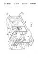
- FIG. 1illustrates a perspective view of an infrared drying system, the present invention
- FIG. 2illustrates a perspective view of a pneumatic assembly for raising and lowering one of the infrared modules
- FIG. 3illustrates a perspective view of an infrared lamp and reflector
- FIG. 4illustrates a exploded perspective view of a module, of an infrared lamp and a reflector
- FIG. 5illustrates a perspective view of a casing assembly and a fan assembly
- FIG. 6illustrates a reflector casing and fan assembly aligned to a side mainframe
- FIG. 7illustrates infrared ray and gas flow through the infrared heating unit
- FIG. sillustrates a perspective view of the heating unit
- FIG. 9illustrates a perspective view of a reflector
- FIG. 10illustrates an electromechanical block diagram of the infrared drying system
- FIG. 11illustrates a timing diagram for all poWer levels
- FIG. 12illustrates a flow chart of the main program loop which updates the lamp controllers
- FIG. 13illustrates a flow chart for processing moisture sensor date interrupts
- FIG. 14illustrates a flow chart for processing of clock interrupts
- FIG. 15is a circuit diagram for the phase lock loop which provides the timing input to procedure NMI.
- FIG. 1illustrates an infrared drying system 10 including opposing infrared drying modules 12 and 14, the subject matter of a co-pending patent application by Anderson, Ser. No. 07/404,928 filed Sept. 8, 1989, entitled “Reflector Assembly for Heating a Subordinate”, and assigned to the same Assignee, and also as later described for drying a traveling web of material 16.
- one embodimentuses opposing infrared drying modules 12 and 14 in close proximity to a moisture sensor profile scanner 18 positioned in a belt and ball bearing track 20.
- Idler rollers 22 and 24support the traveling web of material 16 about the moisture sensor profile scanner 18 and through the opposing infrared drying modules 12 and 14.
- the moisture sensor profile scanner 18connects to a moisture computer 26 for generating moisture content signals and position signals.
- the moisture sensor profile scanner 18, the belt and ball bearing track 20 and the moisture computer 26 including a video monitor 28, keyboard 30 and paper printer 32are commercially available as a system from Moisture Systems Corporation of Hopkinton, Mass.
- the moisture computer 26monitors and controls the moisture sensor profile scanner 18 and the moisture profile is displayed on a high resolution color CRT and can be printed to paper.
- a target profile settingis settable by an operator, such as through the keyboard 30 or a potentiometer 34.
- a control computer 40connects to a lamp computer 42 and controls power controllers 44 and 46 to supply power to each lamp of the infrared drying modules 12 and 14 as later described in detail.
- the lamp computer 42switches the plurality of power controllers 44 and 46 corresponding to the upper and lower infrared drying modules 12 and 14 at particular time intervals of the cycles for the three-phase power as later described in detail.
- Power cable 48connects the power from the power controllers 44 and 46 to the infrared drying modules 12 and 14 as later described in detail.
- a base 60 with support structure 62 including upper members 64 and 66support the belt and ball bearing track 20.
- Upper support structures 68 and 70support the opposing infrared drying modules 12 and 14 about pivot points 72 and 73. Cables 74 and 76 control the pivot movement of the lower infrared drying module 14 with respect to the upper infrared drying module 12.
- FIG. 2illustrates a perspective view of a cable assembly 80 on one side of the upper infrared drying module 12 such as for cable 74 including a pneumatic cylinder 82 and idler pulleys 84, 86, 88, 90 and 92.
- the structuremounts within a cavity 94 of the infrared drying module 12.
- a similar assembly(not shown) which cooperates with cable 176 is located within upper infrared drying module 12 on the opposite side of traveling web 16.
- the reflector 100is preferably anodized clad aluminum in which dimples have been made to provide structural strength.
- the reflector 100comprises a top substantially planar reflector portion 102 having opposed reflector side walls 104 and 106 that are increasingly angled away from each other as they extend downwardly from planar reflector portion 102. The particular angle will of course depend on the application, and specifically, the desired light dissipation pattern.
- Each reflector side wall 104 and 106is bent to form channel bottoms 108 and 110.
- the channel bottoms 108 and 110are substantially U-shaped, and have rounded edges. Square edges, although functional, tend to create deleterious stress points in the reflector material.
- a plurality of holes 112are formed in the reflector 100, as by drilling, so that the majority of their area occurs in the low point of said channel bottoms 108 and 110.
- the reflector 100houses lamp 114.
- Lamp 114is preferably positioned inside reflector 100 near planar reflector portion 102 so as to prevent mechanical interference with the web on shut down.
- Lamp 114emits light of the appropriate wavelength of infrared light, depending on the intended application.
- a suitable infrared lampincludes a 12" long, 2000 watt, 250 volt bulb.
- the lamp ends 116 and 118 of lamp 114sit in aperture 120 of lamp holder 122 (only one shown) which is secured to the reflector casing 124 by suitable means, such as a cap screw and lockwasher (not shown).
- a series of three lamps 114 and reflector means 100are housed in the reflector casing 124.
- the reflector casing 124can of course be designed to house any number of lamps 114, depending on the intended application. This flexibility makes almost any size heating unit possible.
- a reflector 100 and lamp retainer 126is secured to the reflector casing 124, and specifically, to lamp holder 122, such as by fasteners connected through the illustrated holes.
- the reflector casing 124is mounted in side mainframe 128 and a opposing like side mainframe (not illustrated) by securing flanges 130 and 132 of reflector casing 124 to lip 134 of the side 15 mainframe 128.
- Side mainframe 128can hold a plurality of reflector casing assemblies 136 in side-by-side relation.
- FIG. 4illustrates an exploded view of a fan assembly 154 that is mounted on the top of reflector casing 124.
- the center of lamp 114is typically the hottest.
- Convection currents through reflector 100are optimized for cooling the assembly and for heating or drying the substrate where two fans are mounted near the center, in the longitudinal direction, of reflector 100, so that the largest volume of gas is moved at the hottest point.
- fan plate 140has two central apertures 142 and 144 in Which fan 146 and another similar fan and fan guards, such as guard 148 are mounted.
- Fan plate brace 150 and another fan plate brace 152 of FIG. 5are secured to fan plate 140 and fan 146 as shown.
- the fan assembly 154is mounted on reflector casing 124 and on side mainframe 128 as shown in FIG. 3.
- a gasket 156(see FIG. 3), such as a silicone gasket, may be placed between reflector casing 124 and the fan plate 140 to help seal the unit.
- FIG. 5illustrates a reflector casing assembly 136 and fan assembly 154 where all numerals correspond to those elements previously described.
- the reflector casing assembly 136secures to the side mainframe 128.
- the fan assembly 154aligns with the reflector casing assembly 136 and secures to the side mainframe 128.
- FIG. 6illustrates the assembled reflector casing assembly 136 and fan assembly 154 mated with each other and aligned to the side mainframe 128 to form an infrared heating unit 157. All other numerals correspond to those elements previously described.
- FIG. 7illustrates the infrared rays and gas flow in the assembled infrared heating unit 157 where all numerals correspond to those elements previously described.
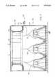
- FIG. 8illustrates a complete heating unit 158 comprised of the upper infrared drying module 12 and the lower infrared drying module 14.
- Each drying moduleis comprised of a plurality of infrared heating units 157 which form the infrared drying modules 12 and 14 which align above and below a web slot 160.
- Side mainframe end covers 162, 164, 166 and 168cooperate to secure about the infrared heating units 157 to form the heating unit 158.
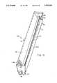
- FIG. 9illustrates a perspective view of an alternative reflector 100.
- Lamp 114is housed in reflector 100 under planar reflector portion 102.
- Lamp ends 118 and 116sit in aperture 120 in each end plate 170.
- Holes 112are spaced apart from each other a distance such that there preferably are about two holes per inch of reflector.
- the holes 112should have sufficient diameters to allow enough gas to pass through for both cooling the reflector and heating or drying the web.
- the holes 112should be substantially hidden from the lamp so as to mitigate deterioration of the reflector material.
- a reflector housing a 12 inch lampabout 2 holes per inch of reflector has been found to be effective.
- dimples 182that can be formed in the surface of reflector 100, and which add strength thereto and improve the diffusion of radiation.
- FIG. 10illustrates a block diagram of the structure of FIG. 1. All numerals correspond to those elements previously described.
- the control computer 40receives moisture content signals, setpoint signal, and corresponding position signals and generates power level signals and corresponding zone signals.
- the lamp computer 42generates control signals for the power controllers 44 and 46 for energizing each infrared lamp over a particular time interval to provide the desired power level.
- the infrared drying system 10includes the three computers, the moisture computer 26, the control computer 40, and the lamp computer 42.
- the first computer, the moisture computer 26controls the moisture sensor profile scanner 18 and the moisture sensing head to provide a display.
- the moisture sensor profile scanner 18generates a moisture content signal, a positioning signal is generated and a setpoint signal is operator set.
- the second computer, the control computer 40generates power level signals and zone signals corresponding to those power level signals in response to the moisture signal.
- This computerdetermines, on averaging the moisture signals, whether more, less or no intensity is required by a lamp, such as an infrared lamp, over that particular zone of the traveling web of material 16.
- the third computerreceives information from the control computer 40 as to each lamp or group of lamps for a particular power level.
- the lamp computer 42provides that the lamp is switched on and off for the correct number of times over a given number of cycles to achieve a particular power level.
- the lamp computer 42controls the power modules to switch power modules on and off as required to provide the desired power level.
- the signals transmitted from the control computer 40 to the lamp computer 42a-42are digital signals in a ring communication configuration. More than one lamp computer 42 can be provided depending upon the size of the infrared drying system 10. This is especially useful for repeating the control signals for the lamp computer 42.
- a closed feedback loopconnects from the lamp computer 42 or the last lamp computer to the control computer 40.
- Each lamp computer 42includes its own phase lock loop.
- the phase lock loopis powered by any one of the three-phase lines as a reference from the main power.
- the power sourcecan also be a combination of the two different phases with respect to the neutral as long as there is the same phase difference between the power that is used to power the lamps and the same frequency.
- a NMI signal, non-mask interruptcontrols the lamp computer 42.
- a flip-flopprovides a condition for initial startup. In a normal startup, the circuits are inhibited from operating and then the VCO turns on after initialization.
- FIG. 11is a basic timing diagram for the illumination of the infrared lamps.
- the intensity of the lampsis controlled by adjusting the duty cycle.
- the overall timingis synchronized to the 60 hz power line. For that reason, the basic timing period is 81/3 milliseconds, which is the period of a half cycle of the 60 hz power cycle.
- the illumination cycleconsists of 16 of the basic timing periods or 1331/3 milliseconds. This is produced by simply counting 16 of the basic timing periods.
- Line 300shows this timing period with pulses 302, 304, and 306 spaced 1331/3 milliseconds apart and corresponding to the sixteenth zero crossing (i.e., half crossing) of phase one of the input power line. Two complete illumination cycles (i.e. 2661/3 milliseconds) are shown for clarity.
- Each of the 1331/3 millisecond illumination cyclesis divided into 16 equal periods of 81/3 milliseconds, corresponding to one-half of one 60 hz power line cycle.
- Each of the 16 lamp intensity levelscorresponds to a different number of energized 8 1/3 millisecond basic periods per 1331/3 millisecond illumination cycle.
- Line 308corresponds to intensity level zero. This means that there are no energized basic periods during the illumination cycle. The result is that the corresponding infrared lamp remains off.
- Intensity level oneis shown by line 310. It provides one basic period (i.e. 81/3 milliseconds) of energy during each illumination cycle (i.e. 1331/3 milliseconds). Pulses 312, 314, and 316 provide the energy as shown. Similarly, line 318 has two energy pulses 317a and 317b providing a total of 161/3 milliseconds of energy during the first 1331/3 millisecond illumination cycle. This corresponds to intensity level two. Lines 319, 320, 322, 324 . . .
- up to 340show the energy pulses for intensity levels 3, 4, 5, 6 . . . up to 15, respectively.
- Line 340shows energy level 15, which has 15 basic periods of energy during the 1331/3 millisecond illumination cycle meaning that the lamp is nearly on for the entire illumination cycle.
- FIGS. 12, 13, and 14show basic operation of the software which controls the entire system and the infrared lamps in particular (see also FIG. 10).
- the main loop of the softwareis the procedure called UPDATE LAMPS shown in FIG. 12. This procedure continues to cycle during system operation to constantly update the intensity of each lamp.
- the interrupt routine of FIG. 13processes the incoming sensor data from the moisture sensor computer.
- the interrupt routine of FIG. 14provides system synchronization. It processes a non-maskable interrupt which is timed from the basic 60 hz power line.
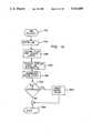
- FIG. 12is a flow chart for the main loop of the program, UPDATE LAMPS. It runs in the normal (i.e. non-interrupt mode).
- the programis entered at system startup at element 200.
- the databaseis initialized at element 202. This includes clearing various counters and resetting certain flags. Reset LED is also turned on.
- element 204The condition of the system fan is checked at element 204. If it is determined that the fan is not on, element 205 sends a pulse to the fan contactor to energize the fan. Notice that control is returned to element 204 to recheck the condition of the fan. The program will not proceed further until the fan is on and up to speed. To do so would risk turning on the lamps without cooling air which might damage the system. To notify the operator, element 203 turns on the reset LED. As a result, reset LED is brightly lighted if the system remains in this loop.
- controlproceeds to element 206 which checks whether the pressure at air bar number one (i.e. within IR heating module 14) is adequate. If the pressure is not adequate, the program remains in this tight loop and the operator is again notified because element 20 keeps reset LED brightly lighted. If element 206 determines that the pressure of air bar number one is adequate, element 208 tests for the same condition with respect to air bar number two (i.e. infrared heating module 16). Notice that any number of critical system parameters may be checked in this fashion.
- element 210updates the controls for the individual lamps. Control of the infrared lamps is through varying of the duty cycle. Because the 60 hz power line provides the basic timing as explained above, the basic time period is 81/3 milliseconds or the period of one-half of one 60 hz power cycle. As further explained above, the illumination cycle is 16 basic time periods.
- the data word fetched for each lampconsists of a word wherein the bit positions correspond to one of the 16 basic timing periods within the illumination cycle.
- the lampis to be energized for the correct basic timing periods.
- reset LEDWhen all lamps have been serviced during the update function 210, control is then transferred to element 203 which toggles reset LED. Notice that in proper operation, reset LED is toggled once per basic timing period causing it to glow at half of full brilliance. This glow shows the operator that the program is functioning properly. If the reset LED is totally extinguished, the program is no longer running. If the reset LED is too bright, it indicates a system problem with the fan or air bar pressures as described above.
- FIG. 13is a flow chart for the procedure which processes the input from the moisture sensing computer.
- the communicationis implemented with a universal asynchronous receiver/transmitter (UART) in the manner known in the art.
- UARTuniversal asynchronous receiver/transmitter
- an interruptis generated which causes entry at element 230.
- the procedureis initialized at element 232 and the UART LED is toggled at element 234.
- Elements 236 and 238store a word and increment bit count.
- Element 240tests whether the word received is valid. If yes, element 242 stores the received word.
- Element 244increments lamp counter, element 246 is for all lamps done, and element 248 is for reset lamp counter. Exit is via element 250.
- FIG. 14is a flow chart of the procedure which supplies the main timing for the system. It is started by a non-maskable interrupt caused by precise timing of the phase lock loop (PLL) circuit. Upon receipt of the interrupt, entry is via element 252. The procedure is initialized at element 254. At each pass through the NMI procedure, a computer is masked for operation from 0-15 by element 256. Depending upon the state of this counter, bits are selected and transferred to the output ports which in turn turn on or off the IR lamps. Control is next given to element 258 which toggles NMI LED after 128 interrupts. Element 260 is increment clock count, element 262 is all 16 intervals, and element 264 is reset clock count. This indicates proper operation of the timing logic to the operator as described above with regard to the other LED's. Exit is via element 266.
- PLLphase lock loop
- FIG. 15is a schematic diagram for the circuitry which provides the basic timing for the system and which selects energization points of the infrared lamps for three-phase power. There are three complete cycles for all three phases of power. Each complete cycle has two zero crossings which basically states that there are going to be six zero crossings for the three phases and the crossings are going to be equally spaced because of the nature of the three phases. By taking the time period from zero, which is a zero crossing for any one of the three phases, the next positive zero crossing or one complete cycle is divided into six equal segments to determine the timing for each of the crossings. One does not want the computer to do anything exactly at the zero crossing.
- phase lock loop circuitis utilized to provide time periods which do not coincide with the zero crossings and provide time periods which are substantially half way between the zero crossings of the 60 hz three-phase power.
- the preferred timing pointsare generated by the phase lock loop circuitry of FIG.
- the power controllersare switched at time period 4 and time period 9 as the time signals are farthest away from each of the zero crossings.
- phase lock loopPLL
- the output of PLL 508is a pulse train at 600 hz which has a fixed phase relationship to the 60 hz power line input.
- the outputis divided by ten by counter 510.
- Outputs 49 and 44 of counter 510are amplified by NPN transistor to become the NMI interrupt (see FIG. 14 for the software which handles this interrupt).
- Appendixsets forth a specific example of an infrared drying system 10 with two opposing lamps with 16 power levels and is expandable to 128 lamps.
- the appendixincludes a general description, a control box description, a program description, a software listing and three flow charts for reset, interrupt, and nonmaskable interrupt.
Landscapes
- Engineering & Computer Science (AREA)
- Mechanical Engineering (AREA)
- General Engineering & Computer Science (AREA)
- Textile Engineering (AREA)
- Physics & Mathematics (AREA)
- General Physics & Mathematics (AREA)
- Automation & Control Theory (AREA)
- Life Sciences & Earth Sciences (AREA)
- Microbiology (AREA)
- Drying Of Solid Materials (AREA)
Abstract
Description
Claims (12)
Priority Applications (1)
| Application Number | Priority Date | Filing Date | Title |
|---|---|---|---|
| US07/104,895US5010659A (en) | 1989-09-08 | 1989-09-08 | Infrared drying system |
Applications Claiming Priority (1)
| Application Number | Priority Date | Filing Date | Title |
|---|---|---|---|
| US07/104,895US5010659A (en) | 1989-09-08 | 1989-09-08 | Infrared drying system |
Publications (1)
| Publication Number | Publication Date |
|---|---|
| US5010659Atrue US5010659A (en) | 1991-04-30 |
Family
ID=22303009
Family Applications (1)
| Application Number | Title | Priority Date | Filing Date |
|---|---|---|---|
| US07/104,895Expired - Fee RelatedUS5010659A (en) | 1989-09-08 | 1989-09-08 | Infrared drying system |
Country Status (1)
| Country | Link |
|---|---|
| US (1) | US5010659A (en) |
Cited By (48)
| Publication number | Priority date | Publication date | Assignee | Title |
|---|---|---|---|---|
| WO1993007326A1 (en)* | 1991-10-03 | 1993-04-15 | Hopkins International, Inc. | Temperature controlled conveyor dryer |
| US5377428A (en)* | 1993-09-14 | 1995-01-03 | James River Corporation Of Virginia | Temperature sensing dryer profile control |
| WO1995002858A1 (en)* | 1993-07-13 | 1995-01-26 | Krieger Gmbh & Co. Kg | Circuit assembly for controlling the output of the heating element of a heater for drying a continuous strip of material |
| US5398425A (en)* | 1994-01-24 | 1995-03-21 | Cherry; Thomas A. | Easy-cleaning infra-red oven |
| US5517768A (en)* | 1993-05-31 | 1996-05-21 | Aviv; Zvi | Apparatus and method for finishing processes |
| US5537925A (en)* | 1993-09-03 | 1996-07-23 | Howard W. DeMoore | Infra-red forced air dryer and extractor |
| US5621983A (en)* | 1996-03-29 | 1997-04-22 | Minnesota Mining And Manufacturing Company | Apparatus and method for deckeling excess air when drying a coating on a substrate |
| US5906862A (en)* | 1997-04-02 | 1999-05-25 | Minnesota Mining And Manufacturing Company | Apparatus and method for drying a coating on a substrate |
| US5930914A (en)* | 1996-04-18 | 1999-08-03 | Infrarodteknik Ab | Method and device for drying a moving web material |
| US5966836A (en)* | 1997-04-11 | 1999-10-19 | Howard W. DeMoore | Infrared heating apparatus and method for a printing press |
| US6015593A (en)* | 1996-03-29 | 2000-01-18 | 3M Innovative Properties Company | Method for drying a coating on a substrate and reducing mottle |
| US6088931A (en)* | 1998-01-27 | 2000-07-18 | Howard W. DeMoore | Interstation infrared heating unit |
| US6152030A (en)* | 1999-02-19 | 2000-11-28 | Fuqua; Rick Lee | Curing apparatus for a multi-color screen printing system |
| US6418638B1 (en)* | 1999-01-18 | 2002-07-16 | Westroc, Inc. | Dryer control system |
| US6465761B2 (en) | 2000-07-24 | 2002-10-15 | Asm America, Inc. | Heat lamps for zone heating |
| WO2002088462A1 (en)* | 2001-04-26 | 2002-11-07 | Ircon Drying Systems Ab | Process for controlling the temperature of a web and a device to use for said temperature control |
| US6536134B1 (en)* | 2001-08-28 | 2003-03-25 | Graphic Specialists, Inc. | Drier for commercial printers |
| US6753512B1 (en)* | 2002-01-02 | 2004-06-22 | Simtek, Inc. | Model-based control system for thermally treating webs |
| US6807906B1 (en)* | 2003-05-16 | 2004-10-26 | Printing Research, Inc. | Zoned ultraviolet curing system for printing press |
| US6818864B2 (en) | 2002-08-09 | 2004-11-16 | Asm America, Inc. | LED heat lamp arrays for CVD heating |
| US6877247B1 (en) | 2000-08-25 | 2005-04-12 | Demoore Howard W. | Power saving automatic zoned dryer apparatus and method |
| US20050241519A1 (en)* | 2003-05-16 | 2005-11-03 | Aylor John E | Heat sink vacuum plate for printing press ultraviolet curing system |
| US20050285313A1 (en)* | 2004-06-24 | 2005-12-29 | Ward Phillip D | Gel/cure unit |
| US20060115778A1 (en)* | 2002-11-08 | 2006-06-01 | Camargo Rangel Paulo G D | Modular infrared irradiation apparatus and its corresponding monitoring devices |
| US20060280825A1 (en)* | 2004-12-03 | 2006-12-14 | Pressco Technology Inc. | Method and system for wavelength specific thermal irradiation and treatment |
| US20070096352A1 (en)* | 2004-12-03 | 2007-05-03 | Cochran Don W | Method and system for laser-based, wavelength specific infrared irradiation treatment |
| EP1785273A1 (en)* | 2005-09-21 | 2007-05-16 | Kba-Giori S.A. | Apparatus for coating a cylinder, in particular a wiping cylinder of an intaglio printing press |
| US20070169373A1 (en)* | 2006-01-25 | 2007-07-26 | Tokyo Electron Limited | Heat processing apparatus and heat processing method |
| US20070227447A1 (en)* | 2006-04-04 | 2007-10-04 | Honeywell International, Inc. | Control of a coating process |
| US20070298188A1 (en)* | 2006-06-26 | 2007-12-27 | Tokyo Electron Limited | Substrate processing method and apparatus |
| US20080216683A1 (en)* | 2005-09-16 | 2008-09-11 | Didier Dupertuis | Apparatus for Coating a Cylinder in Particular a Wiping Cylinder of an Intaglio Printing Press |
| US20080233312A1 (en)* | 2005-08-12 | 2008-09-25 | Dai Nippon Printing Co., Ltd. | Polarizing-Plate-Protecting Film and Polarizing Plate |
| US20080245246A1 (en)* | 2005-09-16 | 2008-10-09 | Didier Dupertuis | Apparatus For Coating a Cylinder, in Particular a Wiping Cylinder of an Intaglio Printing Press |
| US20080305203A1 (en)* | 2007-06-11 | 2008-12-11 | Sidel Participations | Installation for heating the bodies of preforms for blow-moulding containers |
| US20090133286A1 (en)* | 2007-11-26 | 2009-05-28 | David Vallejo | Method and machine for pre-drying stamp-prints |
| US20090214690A1 (en)* | 2004-11-22 | 2009-08-27 | Sidel Participations | Method and installation for the production of containers |
| US20100089906A1 (en)* | 2007-03-02 | 2010-04-15 | Sidel Participations | heating plastics via infrared radiation |
| US20110067260A1 (en)* | 2009-09-22 | 2011-03-24 | Su-Hwan Kim | Lamp heater and drying apparatus including the same |
| US20110131829A1 (en)* | 2009-06-05 | 2011-06-09 | Megtec Systems, Inc. | Infrared Float Bar |
| CN103277993A (en)* | 2013-05-30 | 2013-09-04 | 常熟市众望经纬编织造有限公司 | Far infrared low-temperature drying device capable of achieving energy conservation and emission reduction |
| US20150122794A1 (en)* | 2013-11-01 | 2015-05-07 | Ricoh Company Ltd | Targeted heating of substrate |
| US9481777B2 (en) | 2012-03-30 | 2016-11-01 | The Procter & Gamble Company | Method of dewatering in a continuous high internal phase emulsion foam forming process |
| WO2017077321A3 (en)* | 2015-11-06 | 2017-06-15 | Technijet Digital Limited | Apparatus and method for treating fabric |
| US20180212205A1 (en)* | 2016-12-26 | 2018-07-26 | Wuhan China Star Optoelectronics Technology Co., Ltd. | Ultraviolet irradiation device for package of light-emitting diode |
| US10687391B2 (en) | 2004-12-03 | 2020-06-16 | Pressco Ip Llc | Method and system for digital narrowband, wavelength specific cooking, curing, food preparation, and processing |
| US11448597B2 (en)* | 2018-01-08 | 2022-09-20 | Lg Energy Solution, Ltd. | Method for monitoring dry state of electrode substrate |
| CN120027593A (en)* | 2025-04-24 | 2025-05-23 | 山东客乐思新材料科技有限公司 | A drying method and system for acrylic plate processing |
| US12339064B2 (en)* | 2017-12-06 | 2025-06-24 | Excelitas Noblelight Gmbh | Method for drying a substrate, dryer module for carrying out the method, and dryer system |
Citations (8)
| Publication number | Priority date | Publication date | Assignee | Title |
|---|---|---|---|---|
| US3815254A (en)* | 1972-01-18 | 1974-06-11 | W Mills | Method and apparatus for controlling the amount of moisture removed from material |
| US4501072A (en)* | 1983-07-11 | 1985-02-26 | Amjo, Inc. | Dryer and printed material and the like |
| US4514913A (en)* | 1984-02-07 | 1985-05-07 | Impact Systems, Inc. | Apparatus for drying a moving web having movable dryer modules |
| US4590685A (en)* | 1984-11-09 | 1986-05-27 | Roth Reinhold C | Method & apparatus for uniformly drying paper webs and the like |
| US4594795A (en)* | 1984-10-23 | 1986-06-17 | Erik Stephansen | Air bearing support apparatus for drying a moving web |
| US4693013A (en)* | 1985-06-25 | 1987-09-15 | A. Monforts Gmbh & Co. | Infrared dryer |
| US4698767A (en)* | 1985-08-14 | 1987-10-06 | Electro Sprayer Systems, Inc. | Apparatus and method for controlling infrared dryer for discreet articles |
| US4809608A (en)* | 1987-11-03 | 1989-03-07 | Kenneth Wolnick | Infrared dryer for printing presses |
- 1989
- 1989-09-08USUS07/104,895patent/US5010659A/ennot_activeExpired - Fee Related
Patent Citations (8)
| Publication number | Priority date | Publication date | Assignee | Title |
|---|---|---|---|---|
| US3815254A (en)* | 1972-01-18 | 1974-06-11 | W Mills | Method and apparatus for controlling the amount of moisture removed from material |
| US4501072A (en)* | 1983-07-11 | 1985-02-26 | Amjo, Inc. | Dryer and printed material and the like |
| US4514913A (en)* | 1984-02-07 | 1985-05-07 | Impact Systems, Inc. | Apparatus for drying a moving web having movable dryer modules |
| US4594795A (en)* | 1984-10-23 | 1986-06-17 | Erik Stephansen | Air bearing support apparatus for drying a moving web |
| US4590685A (en)* | 1984-11-09 | 1986-05-27 | Roth Reinhold C | Method & apparatus for uniformly drying paper webs and the like |
| US4693013A (en)* | 1985-06-25 | 1987-09-15 | A. Monforts Gmbh & Co. | Infrared dryer |
| US4698767A (en)* | 1985-08-14 | 1987-10-06 | Electro Sprayer Systems, Inc. | Apparatus and method for controlling infrared dryer for discreet articles |
| US4809608A (en)* | 1987-11-03 | 1989-03-07 | Kenneth Wolnick | Infrared dryer for printing presses |
Cited By (86)
| Publication number | Priority date | Publication date | Assignee | Title |
|---|---|---|---|---|
| WO1993007326A1 (en)* | 1991-10-03 | 1993-04-15 | Hopkins International, Inc. | Temperature controlled conveyor dryer |
| US5517768A (en)* | 1993-05-31 | 1996-05-21 | Aviv; Zvi | Apparatus and method for finishing processes |
| WO1995002858A1 (en)* | 1993-07-13 | 1995-01-26 | Krieger Gmbh & Co. Kg | Circuit assembly for controlling the output of the heating element of a heater for drying a continuous strip of material |
| US5537925A (en)* | 1993-09-03 | 1996-07-23 | Howard W. DeMoore | Infra-red forced air dryer and extractor |
| US5377428A (en)* | 1993-09-14 | 1995-01-03 | James River Corporation Of Virginia | Temperature sensing dryer profile control |
| EP0643165A3 (en)* | 1993-09-14 | 1996-01-17 | James River Corp | Temperature sensing dryer profile control. |
| US5398425A (en)* | 1994-01-24 | 1995-03-21 | Cherry; Thomas A. | Easy-cleaning infra-red oven |
| US5621983A (en)* | 1996-03-29 | 1997-04-22 | Minnesota Mining And Manufacturing Company | Apparatus and method for deckeling excess air when drying a coating on a substrate |
| US6015593A (en)* | 1996-03-29 | 2000-01-18 | 3M Innovative Properties Company | Method for drying a coating on a substrate and reducing mottle |
| US5930914A (en)* | 1996-04-18 | 1999-08-03 | Infrarodteknik Ab | Method and device for drying a moving web material |
| US5906862A (en)* | 1997-04-02 | 1999-05-25 | Minnesota Mining And Manufacturing Company | Apparatus and method for drying a coating on a substrate |
| US5966836A (en)* | 1997-04-11 | 1999-10-19 | Howard W. DeMoore | Infrared heating apparatus and method for a printing press |
| US6088931A (en)* | 1998-01-27 | 2000-07-18 | Howard W. DeMoore | Interstation infrared heating unit |
| US6418638B1 (en)* | 1999-01-18 | 2002-07-16 | Westroc, Inc. | Dryer control system |
| US6152030A (en)* | 1999-02-19 | 2000-11-28 | Fuqua; Rick Lee | Curing apparatus for a multi-color screen printing system |
| US6465761B2 (en) | 2000-07-24 | 2002-10-15 | Asm America, Inc. | Heat lamps for zone heating |
| US6877247B1 (en) | 2000-08-25 | 2005-04-12 | Demoore Howard W. | Power saving automatic zoned dryer apparatus and method |
| US6868623B2 (en) | 2001-04-26 | 2005-03-22 | Ircon Drying Systems Ab | Process for controlling the temperature of a web and a device to use for said temperature control |
| WO2002088462A1 (en)* | 2001-04-26 | 2002-11-07 | Ircon Drying Systems Ab | Process for controlling the temperature of a web and a device to use for said temperature control |
| US20040128856A1 (en)* | 2001-04-26 | 2004-07-08 | Thomas Bjornberg | Process for controlling the temperature of a web and a device to use for said temperature control |
| US6536134B1 (en)* | 2001-08-28 | 2003-03-25 | Graphic Specialists, Inc. | Drier for commercial printers |
| US20030154621A1 (en)* | 2001-08-28 | 2003-08-21 | Graphic Specialists, Inc. | Drier for commercial printers |
| US6668468B2 (en)* | 2001-08-28 | 2003-12-30 | Graphic Specialists, Inc. | Drier for commercial printers |
| US6753512B1 (en)* | 2002-01-02 | 2004-06-22 | Simtek, Inc. | Model-based control system for thermally treating webs |
| US20070116443A1 (en)* | 2002-08-09 | 2007-05-24 | Asm America, Inc. | Led heat lamp arrays for cvd heating |
| US6818864B2 (en) | 2002-08-09 | 2004-11-16 | Asm America, Inc. | LED heat lamp arrays for CVD heating |
| US20050077280A1 (en)* | 2002-08-09 | 2005-04-14 | Ptak John C. | LED heat lamp arrays for CVD heating |
| US7173216B2 (en) | 2002-08-09 | 2007-02-06 | Asm America, Inc. | LED heat lamp arrays for CVD heating |
| US20060115778A1 (en)* | 2002-11-08 | 2006-06-01 | Camargo Rangel Paulo G D | Modular infrared irradiation apparatus and its corresponding monitoring devices |
| US6807906B1 (en)* | 2003-05-16 | 2004-10-26 | Printing Research, Inc. | Zoned ultraviolet curing system for printing press |
| US7669530B2 (en) | 2003-05-16 | 2010-03-02 | Printing Research, Inc. | UV curing assembly having sheet transfer unit with heat sink vacuum plate |
| US20050241519A1 (en)* | 2003-05-16 | 2005-11-03 | Aylor John E | Heat sink vacuum plate for printing press ultraviolet curing system |
| US20040226462A1 (en)* | 2003-05-16 | 2004-11-18 | Demoore Howard W. | Zoned ultraviolet curing system for printing press |
| US20050285313A1 (en)* | 2004-06-24 | 2005-12-29 | Ward Phillip D | Gel/cure unit |
| US8354051B2 (en) | 2004-11-22 | 2013-01-15 | Sidel Participations | Method and installation for the production of containers |
| US20090214690A1 (en)* | 2004-11-22 | 2009-08-27 | Sidel Participations | Method and installation for the production of containers |
| US20100072673A1 (en)* | 2004-11-22 | 2010-03-25 | Sidel Participations | Method and installation for the production of containers |
| US8303290B2 (en) | 2004-11-22 | 2012-11-06 | Sidel Participations | Method and installation for the production of containers |
| US20070096352A1 (en)* | 2004-12-03 | 2007-05-03 | Cochran Don W | Method and system for laser-based, wavelength specific infrared irradiation treatment |
| US10687391B2 (en) | 2004-12-03 | 2020-06-16 | Pressco Ip Llc | Method and system for digital narrowband, wavelength specific cooking, curing, food preparation, and processing |
| US10857722B2 (en) | 2004-12-03 | 2020-12-08 | Pressco Ip Llc | Method and system for laser-based, wavelength specific infrared irradiation treatment |
| US7425296B2 (en) | 2004-12-03 | 2008-09-16 | Pressco Technology Inc. | Method and system for wavelength specific thermal irradiation and treatment |
| US11072094B2 (en) | 2004-12-03 | 2021-07-27 | Pressco Ip Llc | Method and system for wavelength specific thermal irradiation and treatment |
| US20060280825A1 (en)* | 2004-12-03 | 2006-12-14 | Pressco Technology Inc. | Method and system for wavelength specific thermal irradiation and treatment |
| US20080233312A1 (en)* | 2005-08-12 | 2008-09-25 | Dai Nippon Printing Co., Ltd. | Polarizing-Plate-Protecting Film and Polarizing Plate |
| US7913641B2 (en) | 2005-09-16 | 2011-03-29 | Kba-Giori S.A. | Apparatus for coating a cylinder in particular a wiping cylinder of an intaglio printing press |
| US20080245246A1 (en)* | 2005-09-16 | 2008-10-09 | Didier Dupertuis | Apparatus For Coating a Cylinder, in Particular a Wiping Cylinder of an Intaglio Printing Press |
| US20080216683A1 (en)* | 2005-09-16 | 2008-09-11 | Didier Dupertuis | Apparatus for Coating a Cylinder in Particular a Wiping Cylinder of an Intaglio Printing Press |
| US8667927B2 (en) | 2005-09-16 | 2014-03-11 | Kba-Notasys Sa | Apparatus for coating a cylinder, in particular a wiping cylinder of an intaglio printing press |
| EP1785273A1 (en)* | 2005-09-21 | 2007-05-16 | Kba-Giori S.A. | Apparatus for coating a cylinder, in particular a wiping cylinder of an intaglio printing press |
| US20080268168A1 (en)* | 2005-09-21 | 2008-10-30 | Kba-Giors S.A. | Apparatus for Coating a Cylinder, in Particular a Wiping Cylinder of an Intaglio Printing Press |
| WO2007034362A3 (en)* | 2005-09-21 | 2007-07-12 | Kba Giori Sa | Apparatus for coating a cylinder, in particular a wiping cylinder of an intaglio printing press |
| US8302558B2 (en) | 2005-09-21 | 2012-11-06 | Kba-Notasys Sa | Apparatus for coating a cylinder, in particular a wiping cylinder of an intaglio printing press |
| US8782918B2 (en) | 2006-01-25 | 2014-07-22 | Tokyo Electron Limited | Heat processing apparatus and heat processing method |
| US20070169373A1 (en)* | 2006-01-25 | 2007-07-26 | Tokyo Electron Limited | Heat processing apparatus and heat processing method |
| US7980003B2 (en)* | 2006-01-25 | 2011-07-19 | Tokyo Electron Limited | Heat processing apparatus and heat processing method |
| US20110236845A1 (en)* | 2006-01-25 | 2011-09-29 | Tokyo Electron Limited | Heat processing apparatus and heat processing method |
| US20070227447A1 (en)* | 2006-04-04 | 2007-10-04 | Honeywell International, Inc. | Control of a coating process |
| US8181356B2 (en) | 2006-06-26 | 2012-05-22 | Tokyo Electron Limited | Substrate processing method |
| US20070298188A1 (en)* | 2006-06-26 | 2007-12-27 | Tokyo Electron Limited | Substrate processing method and apparatus |
| US7877895B2 (en)* | 2006-06-26 | 2011-02-01 | Tokyo Electron Limited | Substrate processing apparatus |
| US20100089906A1 (en)* | 2007-03-02 | 2010-04-15 | Sidel Participations | heating plastics via infrared radiation |
| US8546277B2 (en) | 2007-03-02 | 2013-10-01 | Sidel Participations | Heating plastics via infrared radiation |
| US8662876B2 (en) | 2007-06-11 | 2014-03-04 | Sidel Participations | Installation for heating the bodies of preforms for blow-moulding containers |
| US20080305203A1 (en)* | 2007-06-11 | 2008-12-11 | Sidel Participations | Installation for heating the bodies of preforms for blow-moulding containers |
| US20090133286A1 (en)* | 2007-11-26 | 2009-05-28 | David Vallejo | Method and machine for pre-drying stamp-prints |
| US10371443B2 (en) | 2009-06-05 | 2019-08-06 | Durr Megtec, Llc | Infrared float bar |
| US20110131829A1 (en)* | 2009-06-05 | 2011-06-09 | Megtec Systems, Inc. | Infrared Float Bar |
| US9228779B2 (en) | 2009-06-05 | 2016-01-05 | Megtec Systems, Inc. | Infrared float bar |
| US9746235B2 (en) | 2009-06-05 | 2017-08-29 | Megtec Systems, Inc. | Infrared float bar |
| US10139159B2 (en) | 2009-06-05 | 2018-11-27 | Babcock & Wilcox Megtec, Llc | Infrared float bar |
| US20110067260A1 (en)* | 2009-09-22 | 2011-03-24 | Su-Hwan Kim | Lamp heater and drying apparatus including the same |
| US8893401B2 (en)* | 2009-09-22 | 2014-11-25 | Samsund Sdi Co., Ltd. | Lamp heater and drying apparatus including the same |
| US9481777B2 (en) | 2012-03-30 | 2016-11-01 | The Procter & Gamble Company | Method of dewatering in a continuous high internal phase emulsion foam forming process |
| US9809693B2 (en) | 2012-03-30 | 2017-11-07 | The Procter & Gamble Company | Method of dewatering in a continuous high internal phase emulsion foam forming process |
| CN103277993A (en)* | 2013-05-30 | 2013-09-04 | 常熟市众望经纬编织造有限公司 | Far infrared low-temperature drying device capable of achieving energy conservation and emission reduction |
| JP2015091652A (en)* | 2013-11-01 | 2015-05-14 | 株式会社リコー | Target heating of substrate |
| US20150122794A1 (en)* | 2013-11-01 | 2015-05-07 | Ricoh Company Ltd | Targeted heating of substrate |
| WO2017077321A3 (en)* | 2015-11-06 | 2017-06-15 | Technijet Digital Limited | Apparatus and method for treating fabric |
| US10782068B2 (en) | 2015-11-06 | 2020-09-22 | Technijet Digital Limited | Apparatus and method for treating fabric |
| EP3371538A2 (en)* | 2015-11-06 | 2018-09-12 | Technijet Digital Limited | Apparatus and method for treating fabric |
| US10193105B2 (en)* | 2016-12-26 | 2019-01-29 | Wuhan China Star Optoelectronics Technology Co., Ltd. | Ultraviolet irradiation device for package of light-emitting diode |
| US20180212205A1 (en)* | 2016-12-26 | 2018-07-26 | Wuhan China Star Optoelectronics Technology Co., Ltd. | Ultraviolet irradiation device for package of light-emitting diode |
| US12339064B2 (en)* | 2017-12-06 | 2025-06-24 | Excelitas Noblelight Gmbh | Method for drying a substrate, dryer module for carrying out the method, and dryer system |
| US11448597B2 (en)* | 2018-01-08 | 2022-09-20 | Lg Energy Solution, Ltd. | Method for monitoring dry state of electrode substrate |
| CN120027593A (en)* | 2025-04-24 | 2025-05-23 | 山东客乐思新材料科技有限公司 | A drying method and system for acrylic plate processing |
Similar Documents
| Publication | Publication Date | Title |
|---|---|---|
| US5010659A (en) | Infrared drying system | |
| EP0416944A1 (en) | Infrared drying system | |
| FI72161C (en) | Device for drying a moving paper web. | |
| EP0416868A1 (en) | Reflector assembly for heating a substrate | |
| US6807906B1 (en) | Zoned ultraviolet curing system for printing press | |
| ATE126906T1 (en) | INTELLIGENT HEATING BLOCK. | |
| EP0895274A4 (en) | LIGHT SOURCE AND DISPLAY USING SAME | |
| CA2014823A1 (en) | Heating apparatus | |
| US5070625A (en) | Oven for the curing and cooling of painted objects and method | |
| BR9706941A (en) | Toaster type toaster with visual control | |
| RU94026894A (en) | INSTALLATION OF AIR CONDITIONING FOR INHABITED PREMISES | |
| US5142795A (en) | Infra-red lamp module | |
| EP1091622A3 (en) | Control apparatus for a light radiation-type rapid heating and processing device | |
| DE69011249D1 (en) | Magnetic field generating system. | |
| EP0653037A4 (en) | Heat transfer unit. | |
| US4873470A (en) | Programmable ultraviolet lamp control system | |
| ITMI910663U1 (en) | FIBERGLASS HOB WITH REFLECTIVE SURFACE ARRANGED IN CORRESPONDENCE WITH A LIGHT AND / OR HEAT GENERATOR, IN PARTICULAR A HALOGEN LAMP REFRESHED BY AIR CIRCULATION | |
| US5825041A (en) | System for optical curing | |
| EP0346081B1 (en) | Air float bar | |
| BR9806163A (en) | Light wave oven and cooking process with multiple cooking modes and sequential lamp operation | |
| ATE76243T1 (en) | CONTROL CIRCUIT FOR A HEATING UNIT. | |
| US3257542A (en) | Infrared heating system | |
| DE69418271D1 (en) | Convection oven | |
| FI974466A0 (en) | Foerfarande Foer reglering av gascirkulation | |
| KR200148393Y1 (en) | Agricultural and Marine Products Drying Equipment |
Legal Events
| Date | Code | Title | Description |
|---|---|---|---|
| AS | Assignment | Owner name:W. R. GRACE & CO. -CONN., 1114 AVENUE OF THE AMERI Free format text:ASSIGNMENT OF ASSIGNORS INTEREST.;ASSIGNOR:TRELEVEN, ROBERT E.;REEL/FRAME:005439/0587 Effective date:19890914 | |
| CC | Certificate of correction | ||
| FPAY | Fee payment | Year of fee payment:4 | |
| AS | Assignment | Owner name:MEGTEC SYSTEMS, INC., WISCONSIN Free format text:CHANGE OF NAME;ASSIGNOR:THERMAL EMISSION CONTROL SYSTEMS, INC.;REEL/FRAME:008820/0239 Effective date:19970909 Owner name:THERMAL EMISSION CONTROL SYSTEMS, INC., WISCONSIN Free format text:ASSIGNMENT OF ASSIGNORS INTEREST;ASSIGNOR:W.R. GRACE & CO.-CONN.;REEL/FRAME:008820/0146 Effective date:19970829 | |
| FEPP | Fee payment procedure | Free format text:PAYOR NUMBER ASSIGNED (ORIGINAL EVENT CODE: ASPN); ENTITY STATUS OF PATENT OWNER: LARGE ENTITY | |
| REMI | Maintenance fee reminder mailed | ||
| LAPS | Lapse for failure to pay maintenance fees | ||
| FP | Lapsed due to failure to pay maintenance fee | Effective date:19990430 | |
| STCH | Information on status: patent discontinuation | Free format text:PATENT EXPIRED DUE TO NONPAYMENT OF MAINTENANCE FEES UNDER 37 CFR 1.362 |