US5010651A - Portable circular saw - Google Patents
Portable circular sawDownload PDFInfo
- Publication number
- US5010651A US5010651AUS07/550,839US55083990AUS5010651AUS 5010651 AUS5010651 AUS 5010651AUS 55083990 AUS55083990 AUS 55083990AUS 5010651 AUS5010651 AUS 5010651A
- Authority
- US
- United States
- Prior art keywords
- saw
- blade
- footplate
- cut
- assembly
- Prior art date
- Legal status (The legal status is an assumption and is not a legal conclusion. Google has not performed a legal analysis and makes no representation as to the accuracy of the status listed.)
- Expired - Lifetime
Links
- 239000000463materialSubstances0.000claimsdescription17
- 230000008859changeEffects0.000claimsdescription3
- 238000000034methodMethods0.000claimsdescription2
- 238000003466weldingMethods0.000description3
- 241000271460Crotalus cerastesSpecies0.000description2
- 230000009467reductionEffects0.000description2
- 230000008901benefitEffects0.000description1
- 230000000994depressogenic effectEffects0.000description1
- 230000000694effectsEffects0.000description1
- 238000009432framingMethods0.000description1
- 230000007246mechanismEffects0.000description1
- 230000004048modificationEffects0.000description1
- 238000012986modificationMethods0.000description1
- 239000011120plywoodSubstances0.000description1
- 230000001105regulatory effectEffects0.000description1
- 238000005728strengtheningMethods0.000description1
Images


Classifications
- B—PERFORMING OPERATIONS; TRANSPORTING
- B27—WORKING OR PRESERVING WOOD OR SIMILAR MATERIAL; NAILING OR STAPLING MACHINES IN GENERAL
- B27B—SAWS FOR WOOD OR SIMILAR MATERIAL; COMPONENTS OR ACCESSORIES THEREFOR
- B27B9/00—Portable power-driven circular saws for manual operation
- B27B9/02—Arrangements for adjusting the cutting depth or the amount of tilting
Definitions
- This inventionis related to portable circular saws.
- itis an improved portable circular saw that includes a footplate such that the saw may be operated at an angle of up to sixty degrees from the perpendicular with respect to a board or other workpiece that is to be cut.
- a portable circular sawcomprises a circular saw blade, a motor to drive the blade, typically through reduction gearing, a support structure, a handle, a blade guard, and a foot or footplate.
- the footplateis typically either a drop foot or a pivot foot, either of which is designed to rest on a surface that is being cut, and is made to move to adjust the depth of cut and provide support for the motor and blade.
- a drop footmoves essentially parallel to itself and generally perpendicular to the axis of rotation of the saw blade and is often arranged to rotate with respect to a cut line to allow the saw to cut at an angle other than perpendicular to the surface of a workpiece.
- a pivot footis constructed to rotate about two axes, one that is parallel to the axis of the saw blade to allow selection of the depth of cut and one that is contained in a plane perpendicular to the axis of the saw blade to allow selection of the angle of cut.
- the footsupports the portable circular saw on the surface of a workpiece to cut at an angle that may be other than perpendicular to the surface.
- Portable circular sawsare typically made in two styles.
- One stylecalled sidewinder, parallel shaft or simply circular saw, has an electric motor that is placed with its shaft parallel to the axis of rotation of a circular saw blade, so that the motor speed is reduced by a set of spur gears, typically, although not necessarily, helical spur gears.
- the other style of portable circular sawcalled a worm drive circular saw, or more recently a hypoid gear variation thereof, has an electric motor that is placed with its shaft in a plane perpendicular to the axis of rotation of the saw blade, so that the speed reduction is produced by a set of worm gears or a hypoid gear set.
- saw cuts at an angle to the surface of the material being cutare guided by a foot such as those described above.
- the sawis rotated about front and rear pivot points on an axis parallel to the cut that is to be made and at an angle determined by a setting of the blade with respect to the foot.
- Pivotal movement of the motor and bladecan also take place about a hinge having an axis parallel to the axis of the rotation of the saw blade.
- the hingemay be associated with either the front or rear pivot. This pivotal movement is effected in a direction so that the motor is raised from or lowered to the surface of the material being cut.
- the motoris rotatably adjustable about the front and rear pivot points with respect to the foot and is typically adjustable continuously up to an angle of 45°, since cuts at angles greater than 45° have had to be made by cutting the workpiece while tilting the saw or the workpiece. This is very dangerous and is not recommended.
- the foothas a quadrant that is usually marked at angles of 0, 15, 30 and 45 degrees and is often fixed with detents to mark these angles for increased convenience in angle cutting.
- An important safety feature that is generally required on portable circular sawsis a blade guard that covers the blade when the saw is not in use and that includes a lower guard cover that rotates about the axis of the saw blade to uncover the teeth of the blade when a cut is being made.
- the blade coverWhen a bevel cut is being started perpendicular to the edge of a board, the blade cover is typically pushed out of position automatically as an operator advances the saw and starts the cut. Normally, when a bevel cut is being started at an angle to the edge of a board, the operator must operate a lever manually to rotate the blade cover out of the way to let the blade make contact with the board.
- Any rotation of the motor and blade with respect to the foot to allow a cut at an angle other than perpendicular to the surface of a workpiecemust provide for proper operation of the moveable lower blade guard so that the blade is covered when the saw is not in use and is retracted to permit a cut when the saw is placed in position to cut on a workpiece.
- the improved portable circular saw disclosed hereinpermits rotation of the saw blade up to an angle of 60° from the vertical with respect to the foot and the surface of the workpiece. This permits the cutting of lumber having a 2-inch nominal dimension in a single cut at 60°.
- the improved sawprovides for operation of the lower blade guard at any angle to which the blade can be set and at any initial angle of cut with respect to the edge of a workpiece.
- the present inventionrelates to a circular saw for cutting 2X lumber at an angle of 60° with the vertical comprising a circular saw blade having a diameter of at least eight and one-quarter inches, a motor and housing assembly attached to the saw blade, a footplate having an opening therein for receiving the saw blade, a front and a rear pivot point on the footplate and connected to the motor and housing assembly for enabling the motor and housing assembly and attached saw blade to be rotated at least 60° from the vertical, the front and rear pivot points having a height above the footplate such that when maintaining the saw motor and housing in substantially the horizontal position, the distance of the lowest portion of the saw blade below the footplate will have a vertical component sufficient to pass through 2X lumber when the blade is rotated 60° from the vertical, a pivoting device preferably coupled to the front pivot point for enabling the depth of the saw extending below the footplate to be adjusted by pivoting the motor and housing assembly upwardly or downwardly about the pivoting device in the plane of the saw blade, and a depth-of-cut bracket mounted on the foot
- the inventionalso relates to a method of enabling a circular saw to cut through 2X lumber at an angle of 60° from the vertical comprising the steps of mounting a circular saw blade having a diameter of at least 81/4 inches on a motor and housing assembly, rotatably mounting the housing assembly on a footplate with the saw blade extending through and below an opening in the footplate a distance such that, when rotated at an angle of 60° from the vertical, the saw blade will have a vertical component sufficient to pass through a 2X piece of lumber, pivotally mounting the housing assembly on the footplate to allow the depth of cut of the saw blade to be adjusted, and adjusting the depth of the cut in conjunction with the rotation of the housing to 60° to provide clearance between the footplate and the housing at the 60° angle thereby enabling a 60° cut to be made through 2X lumber.
- FIG. 1is an isometric view of the novel circular saw
- FIG. 2is a side view of the blade side of the novel circular saw
- FIG. 3Ais a side view of the depth-of-cut bracket associated with the circular saw
- FIG. 3Bis an end view of the depth-of-cut bracket of FIG. 3A;
- FIG. 4is a front view of the quadrant having indicia thereon which indicate the angle of rotation or angle of cut to be made for a given rotation of the motor and saw blade with respect to the footplate;
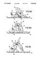
- FIG. 5is a schematic representation of a footplate cross section illustrating the depth-of-cut bracket and the manner of adjusting the depth of cut of the saw by pivoting the saw about a pivot device such as a hinge;
- FIG. 6Ais a schematic representation of a front cross-sectional view of the footplate illustrating the bevel angles of the saw blade with respect to the footplate;
- FIG. 6Bis a schematic representation of a front cross-sectional view of the footplate illustrating the bevel angles of the saw blade with respect to the footplate when the depth of cut of the saw has been adjusted upwardly to provide clearance between the saw blade and the footplate;
- FIG. 7is an isometric view of the spring stop that provides a positive stop at 45° and requires manual operation to allow the saw blade to be adjusted beyond 45° to the 60° position;
- FIG. 8Ais a front view of a forward hinge plate used as a pivoting device about which the motor and saw blade are adjusted for depth of cut;
- FIG. 8Bis a top view of the hinge plate of FIG. 8A;
- FIG. 9is a cross-sectional view of the footplate taken along the width of the footplate and illustrating the rear pivot point
- FIG. 10Ais a front view of the quadrant and hinge with the spring stop in the 0° position
- FIG. 10Bis a front view of the quadrant with the spring stop at 45°;
- FIG. 10Cis a front view of the quadrant with the spring stop at 60°;
- FIG. 11is a plan view of the footplate.
- FIG. 12is a side view of the footplate.
- the novel circular saw for cutting 60° bevel anglesis illustrated in an isometric view in FIG. 1 and in a side view in FIG. 2.
- the saw 10includes an upper guard 12 and a lower guard 14 which houses a circular saw blade 16.
- the saw bladeis attached to a motor in guard 18 by means of a bolt 19.
- the sawis operated by the user grasping handles 20 and 22.
- a foot or footplate 24forms the base for the saw 10 and the saw is mounted to foot 24 by front and rear pivots 26 and 28, respectively. As will be more fully described hereafter, these pivot points allow the circular saw blade 16 to be tilted with respect to the foot 24 from the vertical up to 60° for cutting various beveled angles.
- upper guard 12 of the circular saw 10is attached at hinge 30 for movement in the vertical plane to regulate the depth of cut. While the hinge 30 is shown attached to the front pivot point 26, it could be attached at the rear pivot point 28 by any type of hinge such as a ball-shaped mounting well-known in the art.
- a depth-of-cut bracket 40is associated with rear pivot point 28 and is attached to the saw guard 12 to regulate the depth of cut by pivoting the saw 10 with respect to hinge point 30 in the vertical plane to raise or lower blade 16 with respect to the foot 24.
- Lower guard 14as is well known in the art, pivots about the center of the saw blade 16 to uncover the blade as it is fed into the work to cut a particular material.
- FIG. 3AA side view of the depth-of-cut bracket 40 is illustrated in FIG. 3A.
- the main body 42 of the bracket 40is arcuate in shape and has a center slot 44 through which a bolt on guard 12 can project with a quick lock thereon to lock the saw at a particular angle as designated on the bracket 40 for regulating the depth of cut of the saw.
- the bracketis attached to the footplate by flange 46 which has an orifice 48 therein through which the bolt at the rear pivot point 28 is attached. It will be noted that various indicia 50 are imprinted on the bracket 40. Thus, if the saw were tipped upwardly about pivot point 30 to the top of bracket 40, the saw would be set for cutting plywood.
- FIG. 3Bis an end view of the depth-of-cut bracket 40 illustrating the mounting flange 46 with orifice 48.
- the quadrant 32is illustrated in detail in a front view in FIG. 4.
- Front pivot point 26 of the saw 10 illustrated in FIG. 1 and FIG. 2has a bolt or rivet that passes through orifice 52 of quadrant 32 shown in FIG. 4.
- the quadrant 32is attached to footplate 24 in an well-known manner such as by welding, riveting or bolting. Welding is preferred.
- quadrant 32has indicia 54 thereon including angles from 0°-60°. It also has a slot 56 therein for purposes that will be discussed hereafter.
- the nominal dimension of "2-by" lumberis actually about 11/2 inches in planed lumber or lumber that has been cut to the plane dimension.
- the blade 16In order to cut through a piece of 2X lumber at an angle of 60°, the blade 16 will have to extend below the foot 24 a minimum distance of 3 inches. This is true because the hypotenuse of the right triangle formed by the 60° cut times the cosine of 60° will have to equal 11/2 inches. Since the cosine of 60° is 0.5, the hypotenuse will have to equal 3 inches which would be the vertical depth of the saw extending below footplate 24, as illustrated in FIG. 5. In the schematic illustration as shown in FIG.
- the saw blade 16is illustrated in solid lines positioned along line 58 illustrating the angle of tilt about hinge point 30 necessary for a bevel cut at a 60° angle.
- FIG. 5also illustrates in dotted lines the position of saw blade 16 at the horizontal line 60 and in dotted lines the position of saw blade 16 along the 2X cut line 62.
- the sawwould be held at the desired angle by means of a well-known quick-lock bracket attached to the depth-of-cut bracket 40. It is important that the hinge point 30 be of such a distance above footplate 24 that when the saw is adjusted to line 58 designating a 60° bevel cut, the saw blade 16 protrudes below footplate 24 the minimum distance of 3 inches. The importance of this requirement will be shown with relation to FIGS. 6A and 6B.
- FIG. 6Aillustrates the saw blade 16 along position 64 which is in the vertical plane. Since this is a diagrammatic representation of the saw taken along a cross section of the footplate 24 from one end, it will be understood that the saw blade 16 can be pivoted to the 45° angle (not shown) and to the 60° angle as illustrated by line 68. Note that at the 60° angle along line 68, the bolt 19 which holds the saw blade 16 on the shaft of the drive motor is in contact with the side of footplate 24. Notice, however, in FIG. 6B that when the saw blade 16 is pivoted about hinge point 30 to the 60° line 58 as illustrated in FIG. 5, that the head of the bolt 19 and the blade washer 21 are raised sufficiently that they clear the side of footplate 24 and neither makes contact.
- the desired 60° bevel cut through 2X lumbercan be made without interference between the blade bolt 19 and washer 21 with the workpiece or the footplate.
- a spring stop 70 shown in isometric view in FIG. 7is used in conjunction with the hinge in FIGS. 8A and 8B and the quadrant 32 in FIG. 4 to provide a positive lock at 45° so that the saw blade 16 cannot be tilted beyond 45° until stop spring 70 is physically moved out of place, as will be shown hereafter, to allow the saw to be further tilted to a 60° angle for the 60° cut.
- the 45° cutis automatically obtained and the 60° cut must be manually obtained.
- hinge 30 illustrated in FIG. 8Ahas as an integral part thereof a U-shaped bracket 72 with legs 74 and 76 having orifices 78 and 80 respectively therein for mounting the forward end of upper guard 12 to the hinge 30.
- the orifice 82is coupled to the front pivot point 26 shown in FIG. 1 and FIG. 2.
- the hinge 30has a projecting arm 84 from which extends a projection 86 with an arcuate slot 88 therein.
- the spring stop 70is also mounted about pivot orifice 82 of hinge 30 and has a projection 90 which extends through arcuate orifice 8. Because a circular pin 92 on hinge bracket 30 extends through orifice 94 of spring stop 70, spring stop 70 moves with hinge 30 as it pivots about the center of orifice 82.
- FIG. 10Aillustrates the quadrant 32, hinge 30 and spring stop 70 when the saw blade 16 is in the vertical position.
- a bolt having a head 35 and a body 31 shown in cross-sectionis part of positive lock arm 33 in FIG.
- the sawis automatically positioned at 45° simply by rotating or pivoting the saw and when it reaches 45° it can no longer rotate because spring stop 70 contacts bolt head 35.
- an automatic stopis provided for the 45° position.
- the position for the automatic stop at 45°is illustrated in FIG. 10B.
- the motorcan then be rotated to 60° until the bottom of slot 88 of hinge 30 contacts bolt body 31 as illustrated in FIG. 10C.
- FIG. 9is a cross-sectional view of footplate 24 illustrating the rear pivot point to which the depth-of-cut bracket 40 is preferably attached by projection 46 and orifice 48 (shown in FIG. 3B).
- FIG. 11is a plan view of the footplate 24 that is specially designed for mounting the circular saw 10 such that it can be rotated at an angle to cut a 60° bevel.
- the foot 24has strengthening ribs 94 as well as raised edges 95 on the periphery thereof to give rigidity and strength to the foot 24.
- Front area 98is the area on which the quadrant 32 is mounted as by riveting or preferably welding, as explained previously.
- the saw blade 16extends in a vertical plane through opening 96 with the rear of the saw mounted to pivot point 28 and the front to pivot point 26 on the quadrant bracket 32 when it is attached to area 98. As best seen in FIG.
- edge 99 of foot 24has portions 106 and 109 removed sufficiently to allow the upper guard 12 to clear the foot 24 when the saw is in its 60° position.
- an elongated recess 110is formed in one side of opening 96 of footplate 24 to accommodate the lower guard when it is tipped into the 60° position for cutting a 60° bevel. Without having the elongated recess 110, the saw 10 could not rotate sufficiently far to perform a 60° bevel cut.
- a rib 104is formed on the one side of footplate 24 not only as a strengthener for the narrow side of footplate 24, but also to contact a sloping surface 27 on the lower guard 14 to force the sloping surface and the attached lower guard to move or rotate in the direction of arrow 29 and widen the gap that exists between the front edge 15 of the lower guard 14 and the lower portion of the footplate 24 automatically.
- the opening 102 in edge 99allows the sloped surface 27 on the guard to clear the edge 99 and enables the entire saw to be tipped a full 60°.
- the side view of the footplate 24is illustrated in FIG. 12 wherein the recessed surface 100 for the blade bolt 19 that holds the saw blade to the motor shaft can be seen. Further, the recesses 106 and 109 which allow the upper guard 12 to be accommodated are also shown. Also, the opening 102 and the rib 104 for causing the lower guard 14 to move such that it opens the gap between the front edge 15 of the guard 14 and the footplate 24 can also be seen. Recess 112 and sloped edge 114 on the other side of opening 96 accommodate the other side of upper guard 12 when the saw is tipped to make the 60° bevel cut.
- Orifice 116accommodates the lower leading edge 118 of the upper guard 12 when the unit is tipped in a 60° position.
- the entire sawis designed in conjunction with the footplate 24 so that it can be tipped or rotated 60° to perform a 60° bevel cut without any portion of the saw blade or guards contacting the footplate 24.
- Thisallows the lower guard 14 to be fully and automatically rotated as needed during making the cut and yet it will restore itself automatically to the shielding position when the saw is removed from the workpiece.
- the cutis entirely through a 2X workpiece.
- a novel portable circular sawthat can cut a 60° bevel angle on a workpiece and cut entirely through 2X material at the 60° angle. This is accomplished by using an 81/4 inch diameter blade, mounting the unit on a footplate with front and rear pivot points that are of a distance above the top of the footplate such that at least a minimum amount of the saw blade protrudes below the footplate so that at an angle of 60° the saw can cut entirely through a 2X workpiece.
- the ability of the novel saw to accomplish this 60° cutincludes not only the ability to rotate 60° about front and rear pivot points, but also to pivot upwardly about a hinge or pivoting device so that the various components of the saw which would normally strike the footplate in the 60° position are raised sufficiently to avoid striking the foot piece 24.
- portions of the footplatehave been removed sufficiently to allow the upper and lower guards 12 and 14 to clear any contact with the footplate 24.
Landscapes
- Life Sciences & Earth Sciences (AREA)
- Engineering & Computer Science (AREA)
- Mechanical Engineering (AREA)
- Wood Science & Technology (AREA)
- Forests & Forestry (AREA)
- Sawing (AREA)
- Dovetailed Work, And Nailing Machines And Stapling Machines For Wood (AREA)
- Diaphragms For Electromechanical Transducers (AREA)
- Stringed Musical Instruments (AREA)
- Processing Of Stones Or Stones Resemblance Materials (AREA)
Abstract
Description
Claims (8)
Priority Applications (7)
| Application Number | Priority Date | Filing Date | Title |
|---|---|---|---|
| US07/550,839US5010651A (en) | 1990-07-10 | 1990-07-10 | Portable circular saw |
| AU71059/91AAU633690B2 (en) | 1990-07-10 | 1991-02-14 | Improved portable circular saw |
| CA002036664ACA2036664C (en) | 1990-07-10 | 1991-02-19 | Portable circular saw |
| AT91301331TATE128664T1 (en) | 1990-07-10 | 1991-02-20 | IMPROVED PORTABLE CIRCULAR SAW. |
| EP91301331AEP0466294B1 (en) | 1990-07-10 | 1991-02-20 | Improved portable circular saw |
| DE69113544TDE69113544T2 (en) | 1990-07-10 | 1991-02-20 | Improved portable circular saw. |
| JP3193613AJP2903347B2 (en) | 1990-07-10 | 1991-07-09 | Portable circular saw |
Applications Claiming Priority (1)
| Application Number | Priority Date | Filing Date | Title |
|---|---|---|---|
| US07/550,839US5010651A (en) | 1990-07-10 | 1990-07-10 | Portable circular saw |
Publications (1)
| Publication Number | Publication Date |
|---|---|
| US5010651Atrue US5010651A (en) | 1991-04-30 |
Family
ID=24198772
Family Applications (1)
| Application Number | Title | Priority Date | Filing Date |
|---|---|---|---|
| US07/550,839Expired - LifetimeUS5010651A (en) | 1990-07-10 | 1990-07-10 | Portable circular saw |
Country Status (7)
| Country | Link |
|---|---|
| US (1) | US5010651A (en) |
| EP (1) | EP0466294B1 (en) |
| JP (1) | JP2903347B2 (en) |
| AT (1) | ATE128664T1 (en) |
| AU (1) | AU633690B2 (en) |
| CA (1) | CA2036664C (en) |
| DE (1) | DE69113544T2 (en) |
Cited By (64)
| Publication number | Priority date | Publication date | Assignee | Title |
|---|---|---|---|---|
| US5271155A (en)* | 1991-07-22 | 1993-12-21 | Robert Bosch Gmbh | Hand circular saw |
| US5381602A (en)* | 1992-11-19 | 1995-01-17 | Robert Bosch Gmbh | Electric motor operated hand circular saw |
| US5452515A (en)* | 1993-01-02 | 1995-09-26 | Robert Bosch Gmbh | Hand circular saw with mitre adjusting device |
| US5517763A (en)* | 1994-02-02 | 1996-05-21 | Robert Bosch Gmbh | Hand circular saw with swinging protective hood and miter angle adjusting device |
| USD370162S (en) | 1993-12-17 | 1996-05-28 | Ryobi Motor Products Corp. | Circular saw |
| NL1001299C2 (en)* | 1995-09-26 | 1997-03-28 | Skil Europ Bv | Improved circular saw. |
| US5979525A (en)* | 1998-08-18 | 1999-11-09 | Durney; Max W. | Method and apparatus for scoring a workpiece in advance of sawing |
| US6202311B1 (en) | 1999-07-30 | 2001-03-20 | Black & Decker Inc. | Circular saw with bevel angle adjustment mechanism |
| US6304058B2 (en) | 1998-08-13 | 2001-10-16 | Black & Decker Inc. | Cordless power tool system |
| USD449503S1 (en) | 2000-03-09 | 2001-10-23 | Hitachi Koki Co., Ltd. | Portable electric circular saw |
| US6329788B1 (en) | 1998-08-13 | 2001-12-11 | Black & Decker Inc. | Cordless power tool system |
| USD453099S1 (en) | 2001-07-02 | 2002-01-29 | Black & Decker Inc. | Circular saw |
| USD466385S1 (en) | 2002-01-28 | 2002-12-03 | One World Technologies, Limited | Cordless circular saw |
| US6601305B1 (en)* | 1999-08-16 | 2003-08-05 | Makita Corporation | Circular saws having blade angle adjusting mechanisms |
| AU768563B2 (en)* | 1999-02-19 | 2003-12-18 | Moncrieff, Lois | Profiling device |
| USD486369S1 (en) | 2002-04-17 | 2004-02-10 | Chevron International Trading Co., Ltd | Circular saw with laser alignment system |
| USD501776S1 (en)* | 2003-09-15 | 2005-02-15 | Chervon International Trading Co., Ltd. | Circular saw |
| USD501777S1 (en)* | 2003-09-10 | 2005-02-15 | Chervon International Trading Co., Ltd. | Circular saw |
| USD502373S1 (en)* | 2003-09-15 | 2005-03-01 | Chervon International Trading Co., Ltd. | Circular saw |
| USD503878S1 (en) | 2003-08-11 | 2005-04-12 | One World Technologies Limited | Circular saw |
| US20050217124A1 (en)* | 2002-12-30 | 2005-10-06 | Wolfgang Fuchs | Hand-held circular saw |
| US20050274028A1 (en)* | 2004-06-14 | 2005-12-15 | Hitachi Koki Co., Ltd. | Electric tool |
| USD514411S1 (en) | 2003-08-12 | 2006-02-07 | One World Technologies, Limited | Circular saw |
| USD520831S1 (en)* | 2005-03-09 | 2006-05-16 | Hitachi Koki Co., Ltd. | Portable electric circular saw |
| USD522831S1 (en)* | 2005-01-29 | 2006-06-13 | Positec Power Tools (Suzhou) Co., Ltd. | Circular saw |
| USD525504S1 (en)* | 2004-07-28 | 2006-07-25 | Black & Decker Inc. | Circular saw |
| US20060162171A1 (en)* | 2003-09-12 | 2006-07-27 | Wolfgang Fuchs | Base plate for an electric tool and method for manufacturing same |
| USD538124S1 (en)* | 2006-01-26 | 2007-03-13 | Makita Corporation | Portable electric circular saw |
| USD539108S1 (en)* | 2005-11-24 | 2007-03-27 | Gmca Pty Limited | Powered circular saw |
| US20070074404A1 (en)* | 2005-09-30 | 2007-04-05 | Shisong Zhang | Circular saw |
| USD552953S1 (en)* | 2006-04-26 | 2007-10-16 | Gmca Pty Limited | Circular saw |
| USD572990S1 (en)* | 2007-05-02 | 2008-07-15 | Black & Decker Inc. | Circular saw |
| USD572989S1 (en)* | 2007-05-02 | 2008-07-15 | Black & Decker Inc. | Circular saw |
| CN100418684C (en)* | 2002-01-16 | 2008-09-17 | 日立工机株式会社 | Portable Circular Saw with Circular Saw Blade Angle Control |
| US20080244910A1 (en)* | 2004-05-28 | 2008-10-09 | Scientific Molding Corporation Ltd. | Hand-Held Circular Saw, In Particular Plunge-Cut Saw |
| USD578853S1 (en)* | 2007-12-05 | 2008-10-21 | Robert Bosch Gmbh | Circular saw |
| USD580249S1 (en)* | 2007-05-02 | 2008-11-11 | Black & Decker Inc. | Circular saw |
| US20080305387A1 (en)* | 2007-06-11 | 2008-12-11 | Black & Decker Inc. | Cordless power tool system |
| US20090071017A1 (en)* | 2007-09-13 | 2009-03-19 | Gehret Robert S | Saw with increased depth of cut |
| US20090126206A1 (en)* | 2007-11-16 | 2009-05-21 | Ka Wai Chung | Circular Saw With Cutting Depth Display |
| US20090133559A1 (en)* | 2007-10-04 | 2009-05-28 | Black & Decker Inc. | Power tool |
| USD594724S1 (en)* | 2008-06-20 | 2009-06-23 | Panasonic Electric Works Co., Ltd. | Portable electric round saw |
| USD596006S1 (en)* | 2008-08-21 | 2009-07-14 | Black & Decker Inc. | Cordless circular saw |
| US20090313834A1 (en)* | 2004-09-14 | 2009-12-24 | Martin Charles B | Self-contained vacuum saw |
| US20100024224A1 (en)* | 2008-07-31 | 2010-02-04 | Kuragano Shinji | Portable cutting tool |
| US20100113545A1 (en)* | 2007-02-01 | 2010-05-06 | Steven Coulton | Glyt1 transporter inhibitors and uses thereof in treatment of neurological and neuropsychiatric disorders |
| US20110203121A1 (en)* | 2010-02-24 | 2011-08-25 | Robert Bosch Tool Corporation | Line of Sight Depth of Cut Scale |
| US20130081284A1 (en)* | 2011-09-30 | 2013-04-04 | Robert Bosch Gmbh | Base with Beveled Lateral Side Surface |
| US20130167383A1 (en)* | 2011-12-30 | 2013-07-04 | Robert Bosch Gmbh | Substrate specific cutting guide |
| CN104014868A (en)* | 2013-03-01 | 2014-09-03 | 博世电动工具(中国)有限公司 | Circular saw |
| US20140283396A1 (en)* | 2011-11-15 | 2014-09-25 | Robert Bosch Gmbh | Device for Limiting the Depth of a Cut |
| US9168188B2 (en) | 2007-11-13 | 2015-10-27 | Orthopediatrics Corporation | Cast removal system |
| US9242304B2 (en) | 2004-09-14 | 2016-01-26 | Charles B. Martin | Cutting device with on-board debris collection operable in a plurality of cut angle positions |
| US20160176064A1 (en)* | 2013-02-01 | 2016-06-23 | Makita Corporation | Cutting device |
| USD831710S1 (en)* | 2016-05-20 | 2018-10-23 | Black & Decker Inc. | Power tool |
| US20190030744A1 (en)* | 2012-07-13 | 2019-01-31 | Positec Tower Tools (Suzhou) Co., Ltd. | Portable Cutting Tool |
| CN110114178A (en)* | 2016-12-28 | 2019-08-09 | 工机控股株式会社 | Portable cutting machine |
| US10875109B1 (en) | 2018-04-30 | 2020-12-29 | Kreg Enterprises, Inc. | Adaptive cutting system |
| USD926544S1 (en)* | 2020-01-23 | 2021-08-03 | Flex-Elektrowerkzeuge Gmbh | Safety guard for a machine tool |
| US20230173707A1 (en)* | 2020-12-11 | 2023-06-08 | Techtronic Cordless Gp | Circular saw with adjustable base |
| USD999611S1 (en) | 2020-01-02 | 2023-09-26 | Techtronic Cordless Gp | Circular saw shoe |
| US12083613B2 (en) | 2022-10-18 | 2024-09-10 | Techtronic Cordless Gp | Track saw including plunge lockout mechanism |
| US12208457B2 (en)* | 2020-01-02 | 2025-01-28 | Techtronic Cordless Gp | Circular saw |
| US12263615B2 (en) | 2020-11-23 | 2025-04-01 | Milwaukee Electric Tool Corporation | Circular saw |
Families Citing this family (9)
| Publication number | Priority date | Publication date | Assignee | Title |
|---|---|---|---|---|
| US4982501A (en)* | 1990-03-05 | 1991-01-08 | Black & Decker Inc. | Depth of cut adjustment for a portable circular saw |
| JP2933196B2 (en)* | 1994-10-04 | 1999-08-09 | 均 西本 | Circular saw |
| DE19933145A1 (en)* | 1999-07-20 | 2001-01-25 | Hilti Ag | Sawing device |
| US6898854B2 (en) | 2002-06-07 | 2005-05-31 | Black & Decker Inc. | Modular power tool |
| USD492564S1 (en) | 2002-06-07 | 2004-07-06 | Black & Decker Inc. | Circular saw |
| JP4832008B2 (en)* | 2005-06-14 | 2011-12-07 | リョービ株式会社 | Cutting machine |
| CN107552872B (en)* | 2016-07-01 | 2023-08-11 | 苏州宝时得电动工具有限公司 | Cutting tool |
| CN116329651A (en)* | 2021-12-22 | 2023-06-27 | 株式会社牧田 | Portable cutting machine |
| WO2024095828A1 (en)* | 2022-11-01 | 2024-05-10 | 工機ホールディングス株式会社 | Work machine |
Citations (5)
| Publication number | Priority date | Publication date | Assignee | Title |
|---|---|---|---|---|
| US3262472A (en)* | 1964-05-08 | 1966-07-26 | Black & Decker Mfg Co | Depth and bevel adjustment means for portable power-driven saw |
| US3292673A (en)* | 1963-08-27 | 1966-12-20 | Rockwell Mfg Co | Power operated portable hand saw |
| US3977080A (en)* | 1975-07-30 | 1976-08-31 | Joseph Paul Allaire | Cutting guide for power handsaw |
| US4078309A (en)* | 1977-01-24 | 1978-03-14 | Wilson Ernest V | Miter saw |
| US4589208A (en)* | 1983-08-13 | 1986-05-20 | Matsushita Electric Works, Ltd. | Portable electric circular saw |
Family Cites Families (8)
| Publication number | Priority date | Publication date | Assignee | Title |
|---|---|---|---|---|
| CH276786A (en)* | 1948-10-01 | 1951-07-31 | Reich Maschf Gmbh Karl | Circular saw, in particular hand-held circular saw. |
| CH274032A (en)* | 1948-10-01 | 1951-03-15 | Reich Maschf Gmbh Karl | Circular saw. |
| US3078885A (en)* | 1961-02-27 | 1963-02-26 | Oren P Burch | Portable, power hand-guided saw mounting device |
| DE1403722A1 (en)* | 1961-08-08 | 1969-01-09 | Reich Maschf Gmbh Karl | Circular saw |
| US3733701A (en)* | 1972-01-26 | 1973-05-22 | Singer Co | Lower guard for circular saws |
| JPS5811101A (en)* | 1981-07-13 | 1983-01-21 | 日立工機株式会社 | power cutting tools |
| JPS6198501A (en)* | 1984-10-19 | 1986-05-16 | イワタ建設工業株式会社 | Tilt type cutting tool |
| DE3806813A1 (en)* | 1988-03-03 | 1989-09-14 | Reich Maschf Gmbh Karl | CIRCULAR SAW WITH BASE PLATE |
- 1990
- 1990-07-10USUS07/550,839patent/US5010651A/ennot_activeExpired - Lifetime
- 1991
- 1991-02-14AUAU71059/91Apatent/AU633690B2/ennot_activeCeased
- 1991-02-19CACA002036664Apatent/CA2036664C/ennot_activeExpired - Fee Related
- 1991-02-20ATAT91301331Tpatent/ATE128664T1/ennot_activeIP Right Cessation
- 1991-02-20DEDE69113544Tpatent/DE69113544T2/ennot_activeExpired - Fee Related
- 1991-02-20EPEP91301331Apatent/EP0466294B1/ennot_activeExpired - Lifetime
- 1991-07-09JPJP3193613Apatent/JP2903347B2/ennot_activeExpired - Fee Related
Patent Citations (5)
| Publication number | Priority date | Publication date | Assignee | Title |
|---|---|---|---|---|
| US3292673A (en)* | 1963-08-27 | 1966-12-20 | Rockwell Mfg Co | Power operated portable hand saw |
| US3262472A (en)* | 1964-05-08 | 1966-07-26 | Black & Decker Mfg Co | Depth and bevel adjustment means for portable power-driven saw |
| US3977080A (en)* | 1975-07-30 | 1976-08-31 | Joseph Paul Allaire | Cutting guide for power handsaw |
| US4078309A (en)* | 1977-01-24 | 1978-03-14 | Wilson Ernest V | Miter saw |
| US4589208A (en)* | 1983-08-13 | 1986-05-20 | Matsushita Electric Works, Ltd. | Portable electric circular saw |
Non-Patent Citations (1)
| Title |
|---|
| Power Tool Catalog of Skil Corporation, published Apr. 1989; Skil Price lists for Jan. 1, 1990 and Jul. 1, 1990; and Pairis Enterprises brochure.* |
Cited By (99)
| Publication number | Priority date | Publication date | Assignee | Title |
|---|---|---|---|---|
| US5271155A (en)* | 1991-07-22 | 1993-12-21 | Robert Bosch Gmbh | Hand circular saw |
| US5381602A (en)* | 1992-11-19 | 1995-01-17 | Robert Bosch Gmbh | Electric motor operated hand circular saw |
| US5452515A (en)* | 1993-01-02 | 1995-09-26 | Robert Bosch Gmbh | Hand circular saw with mitre adjusting device |
| USD370162S (en) | 1993-12-17 | 1996-05-28 | Ryobi Motor Products Corp. | Circular saw |
| US5517763A (en)* | 1994-02-02 | 1996-05-21 | Robert Bosch Gmbh | Hand circular saw with swinging protective hood and miter angle adjusting device |
| NL1001299C2 (en)* | 1995-09-26 | 1997-03-28 | Skil Europ Bv | Improved circular saw. |
| EP0765716A1 (en)* | 1995-09-26 | 1997-04-02 | Skil Europe B.V. | Improved circular saw |
| US5933969A (en)* | 1995-09-26 | 1999-08-10 | Skil Europe B.V. | Circular saw |
| US6304058B2 (en) | 1998-08-13 | 2001-10-16 | Black & Decker Inc. | Cordless power tool system |
| US20060108981A1 (en)* | 1998-08-13 | 2006-05-25 | Watson James B | Cordless power tool system |
| US20080284373A1 (en)* | 1998-08-13 | 2008-11-20 | Watson James B | Cordless power tool system having slidably-engaging power source connection |
| US20060107536A1 (en)* | 1998-08-13 | 2006-05-25 | Buck John E | Battery powered circular saw |
| US6329788B1 (en) | 1998-08-13 | 2001-12-11 | Black & Decker Inc. | Cordless power tool system |
| US7423407B2 (en) | 1998-08-13 | 2008-09-09 | Black & Decker Inc. | Cordless power tool system having slidably-engaging power source connection |
| US7005831B2 (en) | 1998-08-13 | 2006-02-28 | Black & Decker Inc. | Cordless power tool system utilizing battery pack connection system with guide rails and guide slots |
| US6996909B1 (en) | 1998-08-13 | 2006-02-14 | Black & Decker Inc. | Battery powered circular saw |
| US6653815B2 (en) | 1998-08-13 | 2003-11-25 | Black & Decker Inc. | Cordless power tool system |
| US7598705B2 (en) | 1998-08-13 | 2009-10-06 | Black & Decker Inc. | Cordless power tool system having cordless power tool and battery pack that employ cooperating rails and grooves for connection of battery pack to cordless power tool |
| US7343683B2 (en) | 1998-08-13 | 2008-03-18 | Black & Decker Inc. | Battery powered circular saw |
| US20040196002A1 (en)* | 1998-08-13 | 2004-10-07 | Watson James B. | Cordless power tool system |
| US5979525A (en)* | 1998-08-18 | 1999-11-09 | Durney; Max W. | Method and apparatus for scoring a workpiece in advance of sawing |
| AU768563B2 (en)* | 1999-02-19 | 2003-12-18 | Moncrieff, Lois | Profiling device |
| US6202311B1 (en) | 1999-07-30 | 2001-03-20 | Black & Decker Inc. | Circular saw with bevel angle adjustment mechanism |
| US6601305B1 (en)* | 1999-08-16 | 2003-08-05 | Makita Corporation | Circular saws having blade angle adjusting mechanisms |
| USD449503S1 (en) | 2000-03-09 | 2001-10-23 | Hitachi Koki Co., Ltd. | Portable electric circular saw |
| USD453099S1 (en) | 2001-07-02 | 2002-01-29 | Black & Decker Inc. | Circular saw |
| CN100418684C (en)* | 2002-01-16 | 2008-09-17 | 日立工机株式会社 | Portable Circular Saw with Circular Saw Blade Angle Control |
| USD466385S1 (en) | 2002-01-28 | 2002-12-03 | One World Technologies, Limited | Cordless circular saw |
| USD486369S1 (en) | 2002-04-17 | 2004-02-10 | Chevron International Trading Co., Ltd | Circular saw with laser alignment system |
| US7975388B2 (en)* | 2002-12-30 | 2011-07-12 | Robert Bosch Gmbh | Hand-held circular saw |
| US20050217124A1 (en)* | 2002-12-30 | 2005-10-06 | Wolfgang Fuchs | Hand-held circular saw |
| USD503878S1 (en) | 2003-08-11 | 2005-04-12 | One World Technologies Limited | Circular saw |
| USD514411S1 (en) | 2003-08-12 | 2006-02-07 | One World Technologies, Limited | Circular saw |
| USD501777S1 (en)* | 2003-09-10 | 2005-02-15 | Chervon International Trading Co., Ltd. | Circular saw |
| US20060162171A1 (en)* | 2003-09-12 | 2006-07-27 | Wolfgang Fuchs | Base plate for an electric tool and method for manufacturing same |
| USD501776S1 (en)* | 2003-09-15 | 2005-02-15 | Chervon International Trading Co., Ltd. | Circular saw |
| USD502373S1 (en)* | 2003-09-15 | 2005-03-01 | Chervon International Trading Co., Ltd. | Circular saw |
| US20080244910A1 (en)* | 2004-05-28 | 2008-10-09 | Scientific Molding Corporation Ltd. | Hand-Held Circular Saw, In Particular Plunge-Cut Saw |
| US8230606B2 (en)* | 2004-06-14 | 2012-07-31 | Hitachi Koki Co., Ltd. | Electric tool |
| US20050274028A1 (en)* | 2004-06-14 | 2005-12-15 | Hitachi Koki Co., Ltd. | Electric tool |
| USD525504S1 (en)* | 2004-07-28 | 2006-07-25 | Black & Decker Inc. | Circular saw |
| US8201335B2 (en)* | 2004-09-14 | 2012-06-19 | Martin Charles B | Self-contained vacuum saw |
| US20090313834A1 (en)* | 2004-09-14 | 2009-12-24 | Martin Charles B | Self-contained vacuum saw |
| US9975268B2 (en) | 2004-09-14 | 2018-05-22 | Charles B. Martin | Portable cutting device with blade guard |
| US9242304B2 (en) | 2004-09-14 | 2016-01-26 | Charles B. Martin | Cutting device with on-board debris collection operable in a plurality of cut angle positions |
| USD522831S1 (en)* | 2005-01-29 | 2006-06-13 | Positec Power Tools (Suzhou) Co., Ltd. | Circular saw |
| USD520831S1 (en)* | 2005-03-09 | 2006-05-16 | Hitachi Koki Co., Ltd. | Portable electric circular saw |
| US8276281B2 (en)* | 2005-09-30 | 2012-10-02 | Positec Power Tools (Suzhou) Co., Ltd. | Circular saw |
| US20070074404A1 (en)* | 2005-09-30 | 2007-04-05 | Shisong Zhang | Circular saw |
| USD539626S1 (en)* | 2005-11-24 | 2007-04-03 | Gmca Pty Limited | Powered circular saw |
| USD539108S1 (en)* | 2005-11-24 | 2007-03-27 | Gmca Pty Limited | Powered circular saw |
| USD538124S1 (en)* | 2006-01-26 | 2007-03-13 | Makita Corporation | Portable electric circular saw |
| USD552953S1 (en)* | 2006-04-26 | 2007-10-16 | Gmca Pty Limited | Circular saw |
| US20100113545A1 (en)* | 2007-02-01 | 2010-05-06 | Steven Coulton | Glyt1 transporter inhibitors and uses thereof in treatment of neurological and neuropsychiatric disorders |
| USD580249S1 (en)* | 2007-05-02 | 2008-11-11 | Black & Decker Inc. | Circular saw |
| USD572989S1 (en)* | 2007-05-02 | 2008-07-15 | Black & Decker Inc. | Circular saw |
| USD572990S1 (en)* | 2007-05-02 | 2008-07-15 | Black & Decker Inc. | Circular saw |
| US20080305387A1 (en)* | 2007-06-11 | 2008-12-11 | Black & Decker Inc. | Cordless power tool system |
| US20090071017A1 (en)* | 2007-09-13 | 2009-03-19 | Gehret Robert S | Saw with increased depth of cut |
| US10695848B2 (en)* | 2007-09-13 | 2020-06-30 | Black & Decker Inc. | Saw with increased depth of cut |
| US20140245621A1 (en)* | 2007-09-13 | 2014-09-04 | Black & Decker Inc. | Saw with Increased Depth of Cut |
| US8695224B2 (en)* | 2007-09-13 | 2014-04-15 | Black & Decker Inc. | Saw with increased depth of cut |
| US8056243B2 (en)* | 2007-10-04 | 2011-11-15 | Black & Decker Inc. | Power tool |
| US20090133559A1 (en)* | 2007-10-04 | 2009-05-28 | Black & Decker Inc. | Power tool |
| US9168188B2 (en) | 2007-11-13 | 2015-10-27 | Orthopediatrics Corporation | Cast removal system |
| US20090126206A1 (en)* | 2007-11-16 | 2009-05-21 | Ka Wai Chung | Circular Saw With Cutting Depth Display |
| USD578853S1 (en)* | 2007-12-05 | 2008-10-21 | Robert Bosch Gmbh | Circular saw |
| USD594724S1 (en)* | 2008-06-20 | 2009-06-23 | Panasonic Electric Works Co., Ltd. | Portable electric round saw |
| US8286358B2 (en)* | 2008-07-31 | 2012-10-16 | Hitachi Koki Co., Ltd. | Portable cutting tool |
| US20100024224A1 (en)* | 2008-07-31 | 2010-02-04 | Kuragano Shinji | Portable cutting tool |
| USD596006S1 (en)* | 2008-08-21 | 2009-07-14 | Black & Decker Inc. | Cordless circular saw |
| US10703008B2 (en) | 2009-04-24 | 2020-07-07 | Charles B. Martin | Portable cutting device with sealing arrangement for vacuum |
| US11331825B2 (en) | 2009-04-24 | 2022-05-17 | Charles B. Martin | Portable cutting device with vacuum and laser guide |
| US8776384B2 (en)* | 2010-02-24 | 2014-07-15 | Robert Bosch Gmbh | Line of sight depth of cut scale |
| US20110203121A1 (en)* | 2010-02-24 | 2011-08-25 | Robert Bosch Tool Corporation | Line of Sight Depth of Cut Scale |
| US9527143B2 (en)* | 2011-09-30 | 2016-12-27 | Robert Bosch Tool Corporation | Base with beveled lateral side surface |
| US20130081284A1 (en)* | 2011-09-30 | 2013-04-04 | Robert Bosch Gmbh | Base with Beveled Lateral Side Surface |
| US9623583B2 (en)* | 2011-11-15 | 2017-04-18 | Robert Bosch Gmbh | Device for limiting the depth of a cut |
| US20140283396A1 (en)* | 2011-11-15 | 2014-09-25 | Robert Bosch Gmbh | Device for Limiting the Depth of a Cut |
| US20130167383A1 (en)* | 2011-12-30 | 2013-07-04 | Robert Bosch Gmbh | Substrate specific cutting guide |
| US20140366389A1 (en)* | 2011-12-30 | 2014-12-18 | Robert Bosch Tool Corporation | Substrate Specific Cutting Guide |
| US11192270B2 (en)* | 2012-07-13 | 2021-12-07 | Positec Power Tools (Suzhou) Co., Ltd. | Portable cutting tool |
| US20190030744A1 (en)* | 2012-07-13 | 2019-01-31 | Positec Tower Tools (Suzhou) Co., Ltd. | Portable Cutting Tool |
| US20160176064A1 (en)* | 2013-02-01 | 2016-06-23 | Makita Corporation | Cutting device |
| CN104014868B (en)* | 2013-03-01 | 2017-09-26 | 博世电动工具(中国)有限公司 | Annular saw |
| CN104014868A (en)* | 2013-03-01 | 2014-09-03 | 博世电动工具(中国)有限公司 | Circular saw |
| USD831710S1 (en)* | 2016-05-20 | 2018-10-23 | Black & Decker Inc. | Power tool |
| CN110114178A (en)* | 2016-12-28 | 2019-08-09 | 工机控股株式会社 | Portable cutting machine |
| US20190388984A1 (en)* | 2016-12-28 | 2019-12-26 | Koki Holdings Co., Ltd. | Portable cutter |
| US11007586B2 (en)* | 2016-12-28 | 2021-05-18 | Koki Holdings Co., Ltd. | Portable cutter |
| CN110114178B (en)* | 2016-12-28 | 2021-07-09 | 工机控股株式会社 | Portable Cutter |
| US10875109B1 (en) | 2018-04-30 | 2020-12-29 | Kreg Enterprises, Inc. | Adaptive cutting system |
| USD999611S1 (en) | 2020-01-02 | 2023-09-26 | Techtronic Cordless Gp | Circular saw shoe |
| US12208457B2 (en)* | 2020-01-02 | 2025-01-28 | Techtronic Cordless Gp | Circular saw |
| USD926544S1 (en)* | 2020-01-23 | 2021-08-03 | Flex-Elektrowerkzeuge Gmbh | Safety guard for a machine tool |
| US12263615B2 (en) | 2020-11-23 | 2025-04-01 | Milwaukee Electric Tool Corporation | Circular saw |
| US20230173707A1 (en)* | 2020-12-11 | 2023-06-08 | Techtronic Cordless Gp | Circular saw with adjustable base |
| US12377569B2 (en)* | 2020-12-11 | 2025-08-05 | Techtronic Cordless Gp | Circular saw with adjustable base |
| US12083613B2 (en) | 2022-10-18 | 2024-09-10 | Techtronic Cordless Gp | Track saw including plunge lockout mechanism |
Also Published As
| Publication number | Publication date |
|---|---|
| ATE128664T1 (en) | 1995-10-15 |
| DE69113544T2 (en) | 1996-04-04 |
| AU633690B2 (en) | 1993-02-04 |
| DE69113544D1 (en) | 1995-11-09 |
| JP2903347B2 (en) | 1999-06-07 |
| JPH05124002A (en) | 1993-05-21 |
| CA2036664C (en) | 1994-07-05 |
| EP0466294B1 (en) | 1995-10-04 |
| AU7105991A (en) | 1992-01-16 |
| CA2036664A1 (en) | 1992-01-11 |
| EP0466294A1 (en) | 1992-01-15 |
Similar Documents
| Publication | Publication Date | Title |
|---|---|---|
| US5010651A (en) | Portable circular saw | |
| US4962685A (en) | Production table saw | |
| US7021186B2 (en) | Bevel adjustment mechanism for a compound miter saw | |
| US4587875A (en) | Portable sawing device utilizing a circular power saw | |
| US5042348A (en) | Compound miter saw | |
| US4265154A (en) | Motorized miter saw fence mounting | |
| US4531441A (en) | Combination table and miter saw | |
| JP2717534B2 (en) | Safety cover device for circular saw machine | |
| JPH0711921Y2 (en) | Tool position setting device for workbench | |
| CA2064619C (en) | Motorized miter box | |
| US4184394A (en) | Motor-driven saw having a circular saw blade | |
| US8181559B1 (en) | Rolling plate assembly attachment for portable power cutting tools including an improved structural design and manufactured out of improved materials, an improved wheel configuration, and an adjustable bevel gear and a cutting guide | |
| US4245533A (en) | Motorized circular miter chop saw | |
| US4078309A (en) | Miter saw | |
| US20070234864A1 (en) | Flip Over Saw | |
| US5271155A (en) | Hand circular saw | |
| JP3286725B2 (en) | Tabletop circular saw machine | |
| GB2291006A (en) | Reversable mitre saw fence | |
| US3706332A (en) | Circular saw guard and linkage | |
| US5737986A (en) | Power saw fence guide | |
| EP1621302B1 (en) | Fence assembly for miter saws | |
| US5540130A (en) | Saw machine | |
| US5454167A (en) | Portable saws | |
| US8122802B2 (en) | Multi-function power saw | |
| KR102151865B1 (en) | Circular sawing machine of electric driving for cutting plate |
Legal Events
| Date | Code | Title | Description |
|---|---|---|---|
| AS | Assignment | Owner name:SKIL CORPORATION, A CORP. OF DE, ILLINOIS Free format text:ASSIGNMENT OF ASSIGNORS INTEREST.;ASSIGNORS:TECHTER, RONALD R.;MANGIALARDI, GREGG M.;ESPARZA, RAYMOND R.;REEL/FRAME:005431/0794;SIGNING DATES FROM 19900810 TO 19900813 | |
| STCF | Information on status: patent grant | Free format text:PATENTED CASE | |
| AS | Assignment | Owner name:S-B POWER TOOL COMPANY, ILLINOIS Free format text:ASSIGNMENT OF ASSIGNORS INTEREST.;ASSIGNOR:SKIL CORPORATION;REEL/FRAME:006495/0992 Effective date:19920924 | |
| FEPP | Fee payment procedure | Free format text:PAYOR NUMBER ASSIGNED (ORIGINAL EVENT CODE: ASPN); ENTITY STATUS OF PATENT OWNER: LARGE ENTITY | |
| FPAY | Fee payment | Year of fee payment:4 | |
| FEPP | Fee payment procedure | Free format text:PAYER NUMBER DE-ASSIGNED (ORIGINAL EVENT CODE: RMPN); ENTITY STATUS OF PATENT OWNER: LARGE ENTITY Free format text:PAYOR NUMBER ASSIGNED (ORIGINAL EVENT CODE: ASPN); ENTITY STATUS OF PATENT OWNER: LARGE ENTITY | |
| FPAY | Fee payment | Year of fee payment:8 | |
| FPAY | Fee payment | Year of fee payment:12 | |
| FEPP | Fee payment procedure | Free format text:PAYER NUMBER DE-ASSIGNED (ORIGINAL EVENT CODE: RMPN); ENTITY STATUS OF PATENT OWNER: LARGE ENTITY Free format text:PAYOR NUMBER ASSIGNED (ORIGINAL EVENT CODE: ASPN); ENTITY STATUS OF PATENT OWNER: LARGE ENTITY | |
| AS | Assignment | Owner name:S-B POWER TOOL CORPORATION, ILLINOIS Free format text:SECRETARY'S CERTIFICATE;ASSIGNOR:S- B POWER TOOL COMPANY;REEL/FRAME:014609/0996 Effective date:20020703 Owner name:CREDO TECHNOLOGY CORPORATION, DELAWARE Free format text:ASSIGNMENT OF ASSIGNORS INTEREST;ASSIGNOR:ROBERT BOSCH TOOL CORPORATION;REEL/FRAME:014615/0215 Effective date:20030101 Owner name:ROBERT BOSCH TOOL CORPORATION, ILLINOIS Free format text:COMBINED MERGER AND CHANGE OF NAME;ASSIGNOR:S-B POWER TOOL CORPORATION;REEL/FRAME:014615/0197 Effective date:20021227 | |
| FEPP | Fee payment procedure | Free format text:PAYER NUMBER DE-ASSIGNED (ORIGINAL EVENT CODE: RMPN); ENTITY STATUS OF PATENT OWNER: LARGE ENTITY Free format text:PAYOR NUMBER ASSIGNED (ORIGINAL EVENT CODE: ASPN); ENTITY STATUS OF PATENT OWNER: LARGE ENTITY |