US5010608A - Support system for reducing formation of decubitus ulcers - Google Patents
Support system for reducing formation of decubitus ulcersDownload PDFInfo
- Publication number
- US5010608A US5010608AUS07/419,891US41989189AUS5010608AUS 5010608 AUS5010608 AUS 5010608AUS 41989189 AUS41989189 AUS 41989189AUS 5010608 AUS5010608 AUS 5010608A
- Authority
- US
- United States
- Prior art keywords
- cells
- support system
- cell
- deflated
- inflated
- Prior art date
- Legal status (The legal status is an assumption and is not a legal conclusion. Google has not performed a legal analysis and makes no representation as to the accuracy of the status listed.)
- Expired - Lifetime
Links
- 208000004210Pressure UlcerDiseases0.000titleabstractdescription21
- 230000015572biosynthetic processEffects0.000titleabstractdescription9
- 239000000463materialSubstances0.000claimsabstractdescription41
- 239000012530fluidSubstances0.000claimsabstractdescription25
- 239000010410layerSubstances0.000claimsdescription81
- 239000007788liquidSubstances0.000claimsdescription36
- 238000010438heat treatmentMethods0.000claimsdescription24
- 238000001816coolingMethods0.000claimsdescription22
- 239000004744fabricSubstances0.000claimsdescription10
- 239000002356single layerSubstances0.000claimsdescription6
- 238000010521absorption reactionMethods0.000claimsdescription5
- 230000004089microcirculationEffects0.000claimsdescription3
- 239000000203mixtureSubstances0.000claimsdescription3
- 230000002572peristaltic effectEffects0.000claimsdescription3
- NBVXSUQYWXRMNV-UHFFFAOYSA-NfluoromethaneChemical compoundFCNBVXSUQYWXRMNV-UHFFFAOYSA-N0.000claims4
- 230000001225therapeutic effectEffects0.000abstractdescription6
- 230000015556catabolic processEffects0.000abstractdescription3
- 210000004027cellAnatomy0.000description185
- 210000003491skinAnatomy0.000description15
- 238000011084recoveryMethods0.000description9
- 230000017531blood circulationEffects0.000description8
- 239000000835fiberSubstances0.000description7
- 238000009835boilingMethods0.000description6
- 230000006870functionEffects0.000description6
- 239000007789gasSubstances0.000description5
- 230000035807sensationEffects0.000description5
- 210000001519tissueAnatomy0.000description5
- 230000004888barrier functionEffects0.000description4
- 230000036541healthEffects0.000description4
- 238000000034methodMethods0.000description4
- -1polyethylenePolymers0.000description4
- 229920002994synthetic fiberPolymers0.000description4
- 238000012360testing methodMethods0.000description4
- 206010011985Decubitus ulcerDiseases0.000description3
- 206010015150ErythemaDiseases0.000description3
- 230000003466anti-cipated effectEffects0.000description3
- 230000009286beneficial effectEffects0.000description3
- 230000000694effectsEffects0.000description3
- 231100000321erythemaToxicity0.000description3
- 230000001771impaired effectEffects0.000description3
- 229920000728polyesterPolymers0.000description3
- 230000009467reductionEffects0.000description3
- 230000004044responseEffects0.000description3
- 210000004872soft tissueAnatomy0.000description3
- 230000003068static effectEffects0.000description3
- 238000012546transferMethods0.000description3
- XLYOFNOQVPJJNP-UHFFFAOYSA-NwaterSubstancesOXLYOFNOQVPJJNP-UHFFFAOYSA-N0.000description3
- 239000004952PolyamideSubstances0.000description2
- 239000004698PolyethyleneSubstances0.000description2
- 239000004743PolypropyleneSubstances0.000description2
- 206010040047SepsisDiseases0.000description2
- 230000004913activationEffects0.000description2
- 230000032683agingEffects0.000description2
- 210000001217buttockAnatomy0.000description2
- 230000008859changeEffects0.000description2
- 230000006378damageEffects0.000description2
- 230000003247decreasing effectEffects0.000description2
- 230000007613environmental effectEffects0.000description2
- 210000003414extremityAnatomy0.000description2
- 230000006872improvementEffects0.000description2
- 208000015181infectious diseaseDiseases0.000description2
- 230000002427irreversible effectEffects0.000description2
- 208000037906ischaemic injuryDiseases0.000description2
- 210000002239ischium boneAnatomy0.000description2
- 230000000474nursing effectEffects0.000description2
- 229920002647polyamidePolymers0.000description2
- 229920000573polyethylenePolymers0.000description2
- 229920001155polypropylenePolymers0.000description2
- 239000005033polyvinylidene chlorideSubstances0.000description2
- 230000002829reductive effectEffects0.000description2
- 230000000284resting effectEffects0.000description2
- 210000000954sacrococcygeal regionAnatomy0.000description2
- 239000000758substrateSubstances0.000description2
- 229920001169thermoplasticPolymers0.000description2
- 238000005303weighingMethods0.000description2
- OHMHBGPWCHTMQE-UHFFFAOYSA-N2,2-dichloro-1,1,1-trifluoroethaneChemical compoundFC(F)(F)C(Cl)ClOHMHBGPWCHTMQE-UHFFFAOYSA-N0.000description1
- RNAMYOYQYRYFQY-UHFFFAOYSA-N2-(4,4-difluoropiperidin-1-yl)-6-methoxy-n-(1-propan-2-ylpiperidin-4-yl)-7-(3-pyrrolidin-1-ylpropoxy)quinazolin-4-amineChemical compoundN1=C(N2CCC(F)(F)CC2)N=C2C=C(OCCCN3CCCC3)C(OC)=CC2=C1NC1CCN(C(C)C)CC1RNAMYOYQYRYFQY-UHFFFAOYSA-N0.000description1
- 102000008186CollagenHuman genes0.000description1
- 108010035532CollagenProteins0.000description1
- 229920000742CottonPolymers0.000description1
- 244000043261Hevea brasiliensisSpecies0.000description1
- 206010020100Hip fractureDiseases0.000description1
- 206010021639IncontinenceDiseases0.000description1
- 208000002720MalnutritionDiseases0.000description1
- 206010031252OsteomyelitisDiseases0.000description1
- 241001494479PecoraSpecies0.000description1
- 239000004793PolystyreneSubstances0.000description1
- 229920001328Polyvinylidene chloridePolymers0.000description1
- 239000004771QuallofilSubstances0.000description1
- 206010040030Sensory lossDiseases0.000description1
- 208000027418Wounds and injuryDiseases0.000description1
- 238000009825accumulationMethods0.000description1
- 230000009471actionEffects0.000description1
- 230000004075alterationEffects0.000description1
- 210000003484anatomyAnatomy0.000description1
- 208000007502anemiaDiseases0.000description1
- 238000013459approachMethods0.000description1
- QVGXLLKOCUKJST-UHFFFAOYSA-Natomic oxygenChemical compound[O]QVGXLLKOCUKJST-UHFFFAOYSA-N0.000description1
- 230000008901benefitEffects0.000description1
- 239000008280bloodSubstances0.000description1
- 210000004369bloodAnatomy0.000description1
- 229920005549butyl rubberPolymers0.000description1
- 230000030833cell deathEffects0.000description1
- 230000001413cellular effectEffects0.000description1
- 230000004087circulationEffects0.000description1
- 230000003749cleanlinessEffects0.000description1
- 229920001436collagenPolymers0.000description1
- 238000009833condensationMethods0.000description1
- 230000005494condensationEffects0.000description1
- 230000034994deathEffects0.000description1
- 230000007423decreaseEffects0.000description1
- 229910003460diamondInorganic materials0.000description1
- 239000010432diamondSubstances0.000description1
- 150000001993dienesChemical class0.000description1
- 238000009826distributionMethods0.000description1
- 229940079593drugDrugs0.000description1
- 239000003814drugSubstances0.000description1
- 230000002500effect on skinEffects0.000description1
- HQQADJVZYDDRJT-UHFFFAOYSA-Nethene;prop-1-eneChemical groupC=C.CC=CHQQADJVZYDDRJT-UHFFFAOYSA-N0.000description1
- 239000006260foamSubstances0.000description1
- 239000006261foam materialSubstances0.000description1
- 210000000527greater trochanterAnatomy0.000description1
- 231100001261hazardousToxicity0.000description1
- 238000010191image analysisMethods0.000description1
- 230000028993immune responseEffects0.000description1
- 230000001939inductive effectEffects0.000description1
- 230000036512infertilityEffects0.000description1
- 208000014674injuryDiseases0.000description1
- 230000003834intracellular effectEffects0.000description1
- 238000011835investigationMethods0.000description1
- 208000028867ischemiaDiseases0.000description1
- 210000001821langerhans cellAnatomy0.000description1
- 229920000092linear low density polyethylenePolymers0.000description1
- 239000004707linear low-density polyethyleneSubstances0.000description1
- 230000007774longtermEffects0.000description1
- 230000001071malnutritionEffects0.000description1
- 235000000824malnutritionNutrition0.000description1
- 238000004519manufacturing processMethods0.000description1
- 239000002184metalSubstances0.000description1
- 238000012544monitoring processMethods0.000description1
- 210000003205muscleAnatomy0.000description1
- 229920003052natural elastomerPolymers0.000description1
- 229920001194natural rubberPolymers0.000description1
- 230000017074necrotic cell deathEffects0.000description1
- 231100000252nontoxicToxicity0.000description1
- 230000003000nontoxic effectEffects0.000description1
- 208000015380nutritional deficiency diseaseDiseases0.000description1
- 239000001301oxygenSubstances0.000description1
- 229910052760oxygenInorganic materials0.000description1
- 206010033675panniculitisDiseases0.000description1
- 230000002085persistent effectEffects0.000description1
- 239000004033plasticSubstances0.000description1
- 229920003023plasticPolymers0.000description1
- 229920000642polymerPolymers0.000description1
- 229920002223polystyrenePolymers0.000description1
- 229920002635polyurethanePolymers0.000description1
- 239000004814polyurethaneSubstances0.000description1
- 239000004800polyvinyl chlorideSubstances0.000description1
- 229920000915polyvinyl chloridePolymers0.000description1
- 230000002035prolonged effectEffects0.000description1
- 230000000717retained effectEffects0.000description1
- 230000002441reversible effectEffects0.000description1
- 210000001991scapulaAnatomy0.000description1
- 210000001732sebaceous glandAnatomy0.000description1
- 229920002545silicone oilPolymers0.000description1
- 229920002379silicone rubberPolymers0.000description1
- 210000004304subcutaneous tissueAnatomy0.000description1
- 238000001356surgical procedureMethods0.000description1
- 210000000106sweat glandAnatomy0.000description1
- 229920001897terpolymerPolymers0.000description1
- 238000010998test methodMethods0.000description1
- 239000004753textileSubstances0.000description1
- 238000001931thermographyMethods0.000description1
- 239000012815thermoplastic materialSubstances0.000description1
- 238000009834vaporizationMethods0.000description1
- 208000019553vascular diseaseDiseases0.000description1
- 229920005609vinylidenefluoride/hexafluoropropylene copolymerPolymers0.000description1
- 210000002268woolAnatomy0.000description1
Images


Classifications
- A—HUMAN NECESSITIES
- A61—MEDICAL OR VETERINARY SCIENCE; HYGIENE
- A61G—TRANSPORT, PERSONAL CONVEYANCES, OR ACCOMMODATION SPECIALLY ADAPTED FOR PATIENTS OR DISABLED PERSONS; OPERATING TABLES OR CHAIRS; CHAIRS FOR DENTISTRY; FUNERAL DEVICES
- A61G7/00—Beds specially adapted for nursing; Devices for lifting patients or disabled persons
- A61G7/05—Parts, details or accessories of beds
- A61G7/057—Arrangements for preventing bed-sores or for supporting patients with burns, e.g. mattresses specially adapted therefor
- A61G7/05769—Arrangements for preventing bed-sores or for supporting patients with burns, e.g. mattresses specially adapted therefor with inflatable chambers
- A61G7/05776—Arrangements for preventing bed-sores or for supporting patients with burns, e.g. mattresses specially adapted therefor with inflatable chambers with at least two groups of alternately inflated chambers
- A—HUMAN NECESSITIES
- A61—MEDICAL OR VETERINARY SCIENCE; HYGIENE
- A61G—TRANSPORT, PERSONAL CONVEYANCES, OR ACCOMMODATION SPECIALLY ADAPTED FOR PATIENTS OR DISABLED PERSONS; OPERATING TABLES OR CHAIRS; CHAIRS FOR DENTISTRY; FUNERAL DEVICES
- A61G2210/00—Devices for specific treatment or diagnosis
- A61G2210/90—Devices for specific treatment or diagnosis for heating
Definitions
- the present inventionrelates to a clinical support system and related devices for use in the reduction of the breakdown of human skin, and especially to reduce the likelihood of formation of decubitus ulcers in persons who are confined to beds, wheelchairs or the like for periods of time or who otherwise are fully or partially immobilized.
- support systemincludes mattresses, cushions, pads and other related support devices, including support systems that may be used for therapeutic or other purposes;
- bottoming outrefers to both collapse of a cell of a clinical support system such that the top portion of the cell comes into contact with the underlying or bottom portion of the cell under the influence of a weight e.g. the weight of a person, and to contact by a person with the underlying portion of the clinical support system between cells;
- human two point discrimination thresholdis measured on a person's back, being the minimum distance at which two objects may be distinguished by touch when the objects are placed on the skin, that distance being understood in the anatomy profession and being approximately 25 mm on a person's back.
- Decubitus ulcerswhich are also referred to as pressure ulcers, pressure sores and bedsores, are a pervasive problem in the health care field, with high cost both in terms of individual human suffering and in the financial cost to society.
- the incidence of decubitus ulcers in hospitalized patientsranges from about 3% to about 17% and may increase to the 20-30% range for hospitalized elderly patients (D. Norton et al, An Investigation of Geriatric Nursing Problems in Hospital, Churchill Livingstone, Edinburgh (1962)).
- the incidencemay be in the range of 30-60% of the patients (Richardson and Mayer, Gerontol. 19 235-247 (1981); Taylor, J. Gerontol. Nurs. 6 389-391 (1980)).
- Decubitus ulcersare localized cellular necroses that tend to develop when soft tissue is compressed between a bony prominence and a firm surface for prolonged periods of time. External pressure exerts its influence by occluding blood flow, leading to ischemic injury. With the interruption of blood flow and hence oxygen supply, a sequence of intracellular events occurs which proceeds to an irreversible stage if the blood flow is not restored. Ischemic injury results in cell death i.e. necrosis, and the accumulation of cell debris within the tissues.
- decubitus ulcersThe most crucial factors in the formation of decubitus ulcers are the intensity and duration of the pressure being applied, with the relationship between these factors generally believed to be a parabolic intensity-duration curve. If the patient remains immobile and in the same position for periods of time that are less than about two hours, the ischemia is reversible and generally no long term or irreversible damage is done to the soft tissues i.e. skin, subcutaneous tissues and muscle, over bony prominences. However, if the period of immobility exceeds about two hours, decubitus ulcers begin to form, which is sometimes referred to as the formation of Stage 1 pressure sores. It is for this reason, in particular, that it is the policy of many hospitals and institutions to position patients about every two hours. However, this practice is not totally effective. In addition, there is a trend towards the care of patients in the home, rather than in a hospital, and in such circumstances nursing care may not be available for twenty four hours/day.
- extrinsic and intrinsic factorsare considered to act to reduce tissue tolerance to pressure.
- Extrinsic factors that exert influence on soft tissueinclude shear friction, moisture and temperature.
- Intrinsic factors that determine the susceptibility of tissue to breakdowninclude sensory loss, impaired mobility, advanced age, malnutrition, vascular disease, anemia, incontinence and infection.
- the present inventionprovides a clinical support system comprising: two sheets of a flexible material in planar overlying relationship and bonded to each other at selected areas so as to provide a plurality of separate cells of selected size and shape in a monolayer between said sheets; said material being sufficiently impermeable to a fluid contained in said cells so that each cell may be alternately and repeatedly inflated and deflated; said cells being of such size and shape and having such intercellular spacing so that, in at least one of the width and length of said clinical support system, the distance between centres of adjacent inflated cells is less than the human two-point discrimination threshold and said clinical support system is capable of supporting a human body without bottoming out either of or between said inflated cells.
- said cellsare of a shape and size such that a weight of 2.5 kg and having a spherical surface with a diameter of 2.67 cm placed on the clinical support system will not cause bottoming out of the clinical support system.
- the present inventionalso provides a support system comprising:
- a clinical support systemcomprising two sheets of a flexible material in planar overlying relationship and bonded to each other at selected areas so as to provide a plurality of separate cells of selected size and shape in a monolayer between said sheets; said material being sufficiently impermeable to a fluid contained in said cells so that each cell may be alternately and repeatedly inflated and deflated; said cells being of such size and shape and having such intercellular spacing so that, in at least one of the width and length of said clinical support system, the distance between centres of adjacent inflated cells is less than the human two-point discrimination threshold and said clinical support system is capable of supporting a human body without bottoming out either of or between said inflated cells; and
- (b)means to inflate and deflate the cells.
- said cellsare of a shape and size such that a weight of 2.5 kg and having a spherical surface with a diameter of 2.67 cm placed on the clinical support system will not cause bottoming out of the clinical support system.
- the means to inflate the cellsis controlled so that when one cell is inflated, adjacent cells are deflated.
- the cellsare capable of being inflated and deflated independently.
- the means to inflate the cellsis a compressor or a liquid that is capable of being vaporized to inflate the cells, especially vaporized by use of electrical heating elements or thermoelectric means.
- each cellis of a geometry that precludes complete collapse of the cell when deflated.
- the present inventionprovides a support system comprising, in sequence, (a) a clinical support system comprising two sheets of a flexible material in planar overlying relationship and bonded to each other at selected areas so as to provide a plurality of separate cells of selected size and shape in a monolayer between said sheets; said material being sufficiently impermeable to a fluid contained in said cells so that each cell may be alternately and repeatedly inflated and deflated;
- said cellsbeing of such size and shape and having such intercellular spacing so that, in at least one of the width and length of said clinical support system, the distance between centres of adjacent inflated cells is less than the human two-point discrimination threshold and said clinical support system is capable of supporting a human body without bottoming out either of or between said inflated cells; (b) means to inflate and deflate the cells; (c) a layer of cushioning material; and (d) a layer of material having a high coefficient of friction.
- said cellsare of a shape and size such that a weight of 2.5 kg and having a spherical surface with a diameter of 2.67 cm placed on the clinical support system will not cause bottoming out of the clinical support system.
- a fabric layeris located above the layer of flexible material, said fabric layer being between a moisture absorption layer and the layer of flexible material.
- the moisture absorption layeris preferably a microporous film layer, preferably a disposable layer.
- the present inventionadditionally provides a cell that is capable of being alternately inflated and deflated, said cell being formed of flexible impermeable thermoplastic material and containing an inert liquid having a boiling point in the range of 0°-50° C., said cell additionally having means to heat and/or cool the liquid.
- the liquidis one or more fluorocarbons, or one or more liquids of the type being developed to replace flurocarbons for environmental reasons, especially such fluorocarbons and liquids having a boiling point in the range of 10°-40° C., especially 20°-34° C.
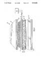
- FIG. 1is a schematic representation of part of a single row of cells of a clinical support system, all of which are shown in an inflated state;
- FIG. 2is a schematic representation of the cells of FIG. 1, some of which are in a deflated state;
- FIG. 3is a schematic representation of an embodiment of a portion of a support system of the present invention.
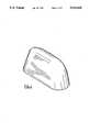
- FIG. 4is a computer simulated drawing of a cell
- FIG. 5is a histogram of data obtained in Example I.
- FIG. 6is a graph of data obtained in Example II.
- FIG. 7is a graph of data obtained in Example III.
- FIG. 8is a graph of the pressure profile as measured in Example IV.
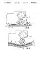
- FIG. 9A and 9Bare schematic sectional representations of the use of support systems having long inflated tubular cells and of support systems of the invention.
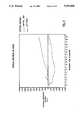
- FIG. 10is a graph of temperature versus recovery time as measured in Example V.
- FIG. 11is a graph of thermal response of tissue versus time as measured in Example VI.
- FIG. 1a single row of cells 1 is shown on a substrate 2, substrate 2 being a layer of flexible material. Cells 1 are separated by spaces 3 that are substantially smaller than the distance, d, between the centres of the cells, as indicated by 4.
- the cells 1are shown as being elongated, but it is to be understood that the cells may be of any convenient shape; nonetheless the cells should be of a size and shape that precludes "bottoming out” i.e. precludes collapse of the cell such that the top portion of the cell comes into contact with the bottom portion of the cell under the influence of a weight e.g. the weight of a patient.
- An example of a cellis shown as a computer simulated drawing in FIG. 4. In use, the cells 1 would be associated with means to inflate and deflate the cells in a controlled manner; such means are not shown.
- the cells 1 of FIG. 1are capable of being inflated and deflated, as is shown in FIG. 2.
- inflated cells 11are separated by a deflated cell 12.
- the distance between the centres of the inflated cellsis less than the human two point discrimination threshold, and thus a person lying on the cells is unable to distinguish by touch that alternate cells are inflated and deflated.
- the patientis generally unable to sense deflation of cells 11 and inflation of cells 12.
- a mattress systemshown generally as 20, is comprised of a closed cell layer 21 on top of a heating element layer 22, a fibre layer 23 and a high friction layer 24.
- a fabric layer 25On top of the closed cell layer 21 are a fabric layer 25 and an outer microporous layer 26.
- the closed cell layer 21has a plurality of cells 27 which may be of the type shown in FIG. 1.
- the cells 27are shown as being elongated and being aligned in both the axial direction of the cells and in the transverse direction. However, the cells could be of alternate shapes and/or be in a more random pattern.
- the cellsare referred to herein as being “separate cells”; it is to be understood however that even though the cells have the physical appearance of being separate cells, any one cell may be interconnected with one or more other cells for purposes of inflation and deflation of the cells.
- Cells 27are capable of being inflated and deflated.
- a variety of meansmay be used to inflate and deflate the cells.
- the cellsmay be attached by means 30 of tubing to a system that will alternately supply a compressed gas e.g. compressed air, at a pressure that is sufficient to inflate cells 27 when in use, and subsequently cool or apply a vacuum to cells 27 to the extent necessary to deflate cells 27.
- the amount of vacuum appliedmay be small i.e. just sufficient to deflate the cells 27 to the extent that cells 27 no longer would support a patient on the mattress system 20.
- Compressors to supply the compressed airtend to be noisy and, alternatively, the supply of compressed gas could be from a source that is remote from the area of use of the mattress system e.g. from a compressor or other source of compressed gas at a remote location.
- the alternating pressure in the cellscould be applied by hydraulic means on a liquid in the cell. Examples of such liquids include water and silicone oils.
- a preferred method of inflating and deflating the cells 27is to incorporate a liquid into the cells.
- the liquidis heated, especially by thermoelectric means, to cause vapour to form and thereby inflate the cells 27; such heating may increase the temperature of the liquid above its boiling point but it may not be necessary to do so, provided that sufficient pressure is generated to inflate the cells 27.
- the pressure in cells 27decreases, and the cells deflate.
- the liquidmust be selected so that sufficient vapour may be generated to cause the cells to inflate while at the same time remaining at a desired or preselected temperature.
- the liquidmay have to be selected for a particular end-use location. For instance, in some locations the ambient temperature around the patient may be as low as about 18° C. whereas in other locations the ambient temperature may reach as high as about 40° C.
- the liquid placed in the cells 27is preferably inert, non-toxic and non-flammable, and not of concern to health authorities with respect to both the patients and persons e.g. doctors and nurses, who tend the patients.
- the cells 27need to be constructed from a material that has adequate barrier properties to the liquid, so that a supply of liquid may be retained in the cells for at least the anticipated period of use of the mattress system; such material is referred to herein as being impermeable. It is to be understood that the anticipated periods of use of a clinical support system could be six months or as long as two years, or longer.
- the materialmay be a multilayered structure, including a coated structure, in order to obtain an acceptable level of impermeability.
- liquids incorporated into cellsinclude fluorocarbons, especially mixtures of chlorofluorocarbons that exhibit changes of vapour pressure over the temperature range used in inflation and deflation of the cells 27, and fluids of the type being developed to replace chlorofluorocarbons for environmental reasons e.g. hydrochlorofluorocarbons.
- fluorocarbons and hydrochlorofluorocarbonsare available from Du Pont Canada Inc. under the trademark Freon, examples of which are sold under the trade designations 114, 113, 22, 11, 123 and 141B.
- the boiling point of the liquidshould be in the range of 0°-50° C., preferably 10°-40° C. Liquids with the lower boiling points of that range could be used for cooling purposes e.g. of limbs or other parts of the body.
- the liquidhas a boiling point in a comfortable range for a patient but below the normal human perspiration threshold, especially in the range of 20°-34° C.
- Heating and cooling layer (thermoelectric layer) 22 located underneath closed cell layer 21has heating and cooling means 28 and 29 that may be used to vaporize or condense the liquid. While reference is made herein to a heating and cooling layer, it is to be understood that in some embodiments the layer may be singularly a heating or cooling layer.
- Heating and cooling means 28 and 29are separate electrical circuits and are associated with adjacent cells 27, heating and cooling means 28 being used to heat and cool one cell and heating and cooling means 29 being used to heat and cool the adjacent cell.
- One of heating and cooling means 28 and 29would normally be associated with each cell so that the inflating and deflating of the cell may be readily controlled. Only two heating and cooling means 28 and 29 might be used to control the entire mattress system or a variety of heating and coolng means could be used to control different parts of the mattress system in a different manner, for example using a microprocessor. It is preferred that the heating and cooling means operate on a low non-hazardous voltage i.e. a voltage substantially lower than that normally used for heating and cooling appliances.
- the flexible materialmust be sufficiently impermeable to permit use of the clinical support system for the anticipated periods of use.
- the nature of the flexible material to meet such impermeability requirementswill depend, in particular, on the fluid contained in the cells of the clinical support system.
- flexible materials suitable for use with an inert gaseous fluide.g. a hydrochlorofluorocarbon, may not be suitable for use if water is used as the fluid, and vice versa, as will be understood by those skilled in the art.
- the flexible materialis preferably a polymeric material and in particular will be a laminated, heat bonded or coated polymeric material.
- the flexible materialis a thermoplastic polymer that has been laminated or coated with a polymeric material that exhibits barrier properties to the liquid to be contained in the cells of the clinical support system.
- the polymeric materialis a linear low density polyethylene that has been coated with or laminated to polyvinylidene chloride (PVDC).
- PVDCpolyvinylidene chloride
- the flexible materialmay be polyethylene, polypropylene, polyvinyl chloride, polyvinylidene chloride, polyester, polyamide, chlorosulphonated polyethylene, vinylidene fluoride/hexafluoropropylene copolymers, polyurethane, ethylene/propylene/diene terpolymers, copolyetherester polymers, silicon rubber, butyl rubber and natural rubber, coated if necessary to obtain the required barrier properties.
- the closed cell layer 21 and the thermoelectric layer 22are shown in FIG. 3 as being located on a layer of fibre 23.
- Layer 23is intended to provide cushioning to and good pressure distribution on the mattress system and thereby provide greater comfort to the patient.
- Layer 23may be formed from a wide variety of fibres or foam materials, including synthetic fibres e.g. polyamide, polyester and/or polypropylene, natural fibres e.g. cotton, cellulosic or wool fibres including sheep skins and the like. In most instances, the fibre layer will be formed from synthetic fibre that has been sufficiently bulked to provide cushioning effects.
- An example of a preferred fibreis Quallofil® polyester fibre that is used in the manufacture of pillows.
- layer 23may be an air mattress.
- the fibre layer 23is shown as being located on friction layer 24.
- the friction layeris provided for stability and safety of the patient, especially to prevent the mattress system from sliding off the bed or other structure on which it may be used.
- a variety of friction layer materialsare known, including foamed thermoplastic polymers e.g. polystyrene, woven textile structures, Velcro® materials and the like.
- the mattress system shown in FIG. 3has two layers superimposed on the closed cell layer.
- the layer shown immediately adjacent to the closed cell layeris a fabric layer, 25, which is primarily intended as a cover sheet or a sheet enclosing the mattress system of the invention, to retain the integrity of the mattress system and for aesthetic reasons, as well as for reasons of cleanliness and sterility to prevent infections.
- the outer layer shownis a microporous layer, 26, which is primarily intended for comfort of the patient. In particular, the microporous layer 26 permits perspiration or other moisture associated with the patient to be removed from the location of the patient, and improve the comfort of the patient.
- the microporous layeris intended to be a disposable layer.
- the fabric layer 25 and microporous layer 26must be of a thickness and formed from materials such that the beneficial effects of the operation of the closed cell layer 22 are not negated.
- the outer layercould be a non-stick layer, especially such a layer that would be used with burn patients or in some therapeutic end-uses.
- a patientis placed on the mattress system, in contact with the microporous layer, or a sheet or similar layer over the microporous layer.
- the mattress systembe constructed such that the cells are aligned obliquely to the axis of the patient body, and in embodiments aligned transversely to the body.
- the cells of the closed cell layerare then alternately inflated and deflated e.g. by applying heat using the heating element layer, and then allowing the liquid to cool or actively cooling the liquid.
- the cycle of inflation and deflationmay be varied, from one minute to in excess of one hour.
- the cycleshould however be more frequent than once every two hours. Different cycles could be used for different areas of the body e.g. those areas where the body exerts greater pressure could be on a shorter cycle than areas where less pressure is exerted, or different cycles could be used for therapeutic or other reasons; it is to be expected that there will be different optimal cycle times depending on the intended use of a mattress system or clinical support system.
- cycle time for inflation and deflation of the cellsactually includes the period of time required for transfer of fluid out of or into a cell in order to actually effect the deflation and inflation of the cell, or for condensation or vapourization of fluid wholly contained within a cell, as well as the period of time during which the cell is inflated or deflated.
- a period for transfer of fluidis finite and may be minutes in length.
- the beneficial effects of deflation of a cellespecially restoration of normal microcirculation in the layers of the skin adjacent the deflated cell, are primarily limited to the period of time when the cell is not supporting a patient, which may be significantly shorter than the cycle time.
- the period of time for transfer of fluid in relation to the cycle timebecomes more important at short cycle times, and may need to be considered in the operation of systems of the invention.
- the inflation and deflation of cellsis generally described herein in the sense that as one cell is inflated, an adjacent cell is deflated. It is to be understood that such inflation and deflation may occur simultaneously or in sequence, the latter involving inflation of a cell followed by deflation of an adjacent cell.
- the inflation and deflationmay be carried out in the manner of a wave passing across the clinical support system, including according to a peristaltic cycle; in some instances a patient may have a sensation of such wave or peristaltic action but the action may have e.g. beneficial therapeutic effects and could be used for that or other reasons.
- a cell that is inflatedwould be surrounded by cells that are deflated, and vice versa, or a row of cells may be inflated and the immediately adjacent row of cells deflated, or other configurations of inflated and deflated cells may be used provided that the arrangement of inflated and deflated cells is capable of supporting a patient, as described herein.
- the mattress system of the present inventionprovides alternating support for a patient in a manner that the patient has little or no sensation of the alternating support being provided by the mattress system i.e. parts of the patients body are alternately being supported and not supported with the patient having little or no sensation of movement in the bed on which they are lying. Any such sensation could be very disconcerting to the patient.
- the spacing, in at least one direction, of the inflated cells at distances that are less than the human two point discrimination thresholdsubstantially eliminates or overcomes any sensation and permits the mattress system to perform its intended function.
- the pressure exerted on the patient's body juxtaposed to a deflated cellis less than the human internal capillary threshold e.g.
- Capillary pressure thresholde.g. the surface pressure above which capillaries can be expected to collapse, is about 20-32 mm Hg, depending on the patient and the area of the patient in contact with the mattress system.
- the clinical support systemis capable of supporting a human body without bottoming out either of or between the inflated cells.
- the human bodyis simulated by a spherical surface.
- the following proceduremay be used to determine whether a clinical support system is capable of supporting a human body without bottoming out: the procedure uses a jig having a head with a spherical surface having a diameter of 2.67 cm, the head having an actual diameter of 7.5 cm.
- the jigalso has a rod axially attached to the head on the side opposite the spherical surface, the rod being adapted to receive weights.
- the jigis placed on a surface of cells such that the jig is centrally located over a deflated cell and supported by two adjacent inflated cells. Weights having an axial hole are then added to the jig, using the rod, until the surface of the jig contacts the bottom surface of the deflated cell; at such time, the total weight of the jig should be at least 2.5 kg. Under such circumstances, the cells of the clinical support system would be of a shape and size such that a weight of 2.5 kg and having a spherical surface with a diameter of 2.67 cm placed on the clinical support system would not cause bottoming out of the clinical support system.
- FIG. 9Aa portion of a human torso, generally indicated by 40, is shown on a mattress or cushion system 41 having large inflatable cells 42, only one of which is shown in cross-section.
- the inflatable cell 42is shown as having bottomed out at area 43, which is the region of the cell directly under the ischium 44 of the torso 45, with the gas in the inflated cell 42 being shown as having been forced away from the area 43 at which the cell has bottomed out, in the direction of the arrows 45.
- FIG. 9Bthe torso 40 is shown on a mattress system of the present invention.
- the mattress systemis comprised of a monocellular layer 46 of cells, which are shown as being alternately inflated cells 47 and deflated cells 48.
- the layer of cellsis attached to a flexible thermoelectric layer 49.
- Flexible thermoelectric layer 49has located therein a series of heating and cooling circuits 50, each circuit 50 being located under either an inflated cell 47 or a deflated cell 48; in the embodiment shown, the heating and cooling circuits 50 under an inflated cell 47 are heating the gas 52 in the cell whereas the heating and cooling circuits 50 under a deflated cell 48 are cooling the vapour in the cell.
- the flexible layer 49is shown as being located on a fibre layer 51. As is illustrated in FIG.
- the torsois resting on the inflated cells 47 and is not bottoming out and touching the surface of the deflated cells 48.
- the torso located above the deflated cells 48has no pressure exerted on it.
- Activation of the heating circuits below the deflated cells 48 and activation of the cooling circuits underneath the inflated cells 47will cause a reversal, such that the portion of the torso now shown as in contact with the inflated cells will become out of contact with the cells, and vice versa.
- the mattress systems of the present inventionfunction below both the capillary pressure threshold and the two point discrimination threshold, thereby providing the patient with the benefits of enhanced circulation of blood and a reduced tendency for formation of decubitus ulcers and at the same time provide the patient with comfort.
- the mattress systemis easy to use, especially when a liquid capable of under going a phase change is used to provide inflation and deflation of the cells, may be readily cleaned and may be operated in a quiet manner.
- the mattress systemcould be operated by a microprocessor and be portable i.e. it is adaptable to portable use e.g. on wheelchairs and other portable systems, including for limbs and other parts of the body, which offers the patient the possibility of being mobile.
- the liquid in the cellscould be cooled, to permit cooling all or part of a person's body e.g. as a cooling wrap for use in surgery or for therapeutic reasons.
- support system of the inventionhave been generally described herein with reference to medical uses i.e. as mattress systems, it is to be understood that the support systems may be used in a variety of forms and for a wide variety of end uses; in many such end uses, the systems would be more commonly referred to by other names, including support systems, seats, chairs and the like.
- systems described hereinmay be used in the health care, transportation and recreation businesses, examples of which include aircraft, automobile, office, home, truck and other seating.
- Holes of circular cross-section and differing in diameterwere cut in a series of metal plates of different thicknesses.
- the diameters of the holeswere as follows: 31.5 mm, 39.0 mm, 45.0 mm and 51.3 mm.
- the plateswere of thicknesses of 4.2 mm, 5.4 mm, 6.6 mm and 7.8 mm.
- the ischial prominence of a humanwas placed, in turn, over each of the holes; the human was a healthy male aged 46, height 173 cm, weighing approximately 84 kg and of average build.
- a pressure sensing devicewas placed in or on the opposite side of the hole, such that the desired excursion was obtained.
- the sensing devicewas on a wooden surface so that the pressure, if any, exerted by the human on the device i.e. at the plane of the opposite side of the hole, could be measured.
- cell dimensions that would support a human body in a variety of positionswere determined e.g. ischium in the sitting position, greater trochanter lying in the side position, and the sacrum and scapula in the supine position.
- Example IIwas repeated, using the holes aligned in the transverse direction. The results obtained are shown in FIG. 7.
- Example IIshow that where the long axis of the holes was aligned in the anterior/posterior direction, only short cell lengths of 20-36 mm at widths of 18-34 mm gave pressures of less than the capillary pressure threshold. In contrast, the results of Example III show that much longer cells could be tolerated.
- the pressure exerted by a male lying in the supine position on a mattress of the type used in hospitals and on a synthetic fibre layer that was on the mattresswas measured at a plurality of positions on both the mattress and the layer in order to illustrate the pressure profile of a patient.
- the results obtainedare shown in FIG. 8.
- the three areas of high pressure exerted by the humanwere, in descending order, the buttocks, the shoulders and the head.
- the use of the synthetic fibre layer on the mattressresulted in a substantial reduction in the pressure exerted in the above three areas, that reduction being as high as about 60% in the area of the shoulders, but the pressure was still approximately an order of magnitude above the capillary threshold level in all three positions.
- thermographic cameraThe recovery to the normal (pretest) skin temperature of a person's buttocks following various period of time in a sitting position was monitored using a thermographic camera.
- the personwas a healthy male aged 46, height 173 cm, weighing approximately 84 kg and of average build.
- resultsshow that the recovery time increased exponentially with the length of the period of sitting. Moreover, the results show that recovery from sitting on a mattress system of the present invention for 30 minutes is almost as rapid as from sitting on the soft cushion for 5 minutes and significantly better than from sitting on the cushion for 7 minutes; it will be noted that the regression lines through the data for cushions at 3 and 5 minutes and for the mattress system of the invention tend to converge at about six minutes, whereas the regression lines for data with cushions at longer periods of time indicate a substantially longer period for recovery.
- the time of recovery to normal blood circulation in the pressure relief phase over deflated cells in a mattress system of the present inventionshould be matched with the pressure duration phase over inflated cells.
- the resultsshow that a suitable cycle frequency of a mattress system of the present invention for use by the person described above in the sitting position would be approximately 10 minutes.
- the recovery of skin temperature of a person's sacral region following two hours in the supine positionwas monitored with infra red thermography.
- the personwas a healthy male aged 46, height 173 cm, weight approximately 84 kg and of average build.
- the personwas placed in the supine position on a standard hospital bed or on a mattress system of the present invention operating on a ten minute cycle time. Following a period of two hours on the bed or mattress, the person was repositioned on his right side for immediate monitoring of the sacral region using the thermographic camera of Example V.
- the average temperature change with time relative to control temperature for the personwas measured. The results obtained are shown in FIG. 11.
- the thermal response following the two hour period on the hospital bedindicates an erythema paratrimma, as shown by the persistent elevation in temperature relative to the control.
- Erythema paratrimmais characterized by an immediate skin reddening and temperature elevation following a period of stasis over a pressure point.
- the thermal responseapproached normal temperature after 15 minutes without inducing erythema paratrimma.
Landscapes
- Health & Medical Sciences (AREA)
- Nursing (AREA)
- Life Sciences & Earth Sciences (AREA)
- Animal Behavior & Ethology (AREA)
- General Health & Medical Sciences (AREA)
- Public Health (AREA)
- Veterinary Medicine (AREA)
- Invalid Beds And Related Equipment (AREA)
Abstract
Description
Claims (36)
Priority Applications (1)
| Application Number | Priority Date | Filing Date | Title |
|---|---|---|---|
| US07/419,891US5010608A (en) | 1989-10-11 | 1989-10-11 | Support system for reducing formation of decubitus ulcers |
Applications Claiming Priority (1)
| Application Number | Priority Date | Filing Date | Title |
|---|---|---|---|
| US07/419,891US5010608A (en) | 1989-10-11 | 1989-10-11 | Support system for reducing formation of decubitus ulcers |
Publications (1)
| Publication Number | Publication Date |
|---|---|
| US5010608Atrue US5010608A (en) | 1991-04-30 |
Family
ID=23664180
Family Applications (1)
| Application Number | Title | Priority Date | Filing Date |
|---|---|---|---|
| US07/419,891Expired - LifetimeUS5010608A (en) | 1989-10-11 | 1989-10-11 | Support system for reducing formation of decubitus ulcers |
Country Status (1)
| Country | Link |
|---|---|
| US (1) | US5010608A (en) |
Cited By (63)
| Publication number | Priority date | Publication date | Assignee | Title |
|---|---|---|---|---|
| US5103518A (en)* | 1989-08-01 | 1992-04-14 | Bio Clinic Corporation | Alternating pressure pad |
| US5311623A (en)* | 1991-09-12 | 1994-05-17 | Hendi Elias A M | Hydropneumatic mattress |
| US5373595A (en)* | 1993-03-12 | 1994-12-20 | Irvin Industries Canada Ltd. | Air support device |
| US5549743A (en)* | 1993-06-22 | 1996-08-27 | Genesis Composites, L.C. | Composite microsphere and lubricant mixture |
| US5592706A (en)* | 1993-11-09 | 1997-01-14 | Teksource, Lc | Cushioning device formed from separate reshapable cells |
| US5606754A (en) | 1989-03-09 | 1997-03-04 | Ssi Medical Services, Inc. | Vibratory patient support system |
| US5611772A (en)* | 1994-03-15 | 1997-03-18 | Kabushiki Kaisha Fuji Iryoki | Air massage device |
| US5651151A (en)* | 1993-10-19 | 1997-07-29 | Huntleigh Technology Plc | Alternating pressure pad |
| US5701622A (en)* | 1996-01-16 | 1997-12-30 | Sentech Medical Systems, Inc. | Pulsating operating table cushion |
| US5749111A (en)* | 1996-02-14 | 1998-05-12 | Teksource, Lc | Gelatinous cushions with buckling columns |
| US5787531A (en)* | 1994-07-08 | 1998-08-04 | Pepe; Michael Francis | Inflatable pad or mattress |
| WO1998036665A1 (en) | 1997-02-24 | 1998-08-27 | Micropulse, Inc. | Mattress support system |
| EP0862901A1 (en)* | 1997-03-05 | 1998-09-09 | Ohmeda Inc. | Thermoelectric infant mattress |
| EP0872197A2 (en) | 1997-03-24 | 1998-10-21 | Mark Hagopian | A low air loss patient support system providing active feedback pressure sensing and correction capabilities for use as a bed mattress and a wheelchair seating system |
| US5845350A (en)* | 1996-02-16 | 1998-12-08 | Infant Advantage, Inc. | Cradle mattress |
| US5881409A (en)* | 1993-06-22 | 1999-03-16 | Teksource, Ll | Puff-quilted bladders for containing flowable cushioning medium |
| US5901391A (en)* | 1996-06-13 | 1999-05-11 | Hamamatsu Photonics K.K. | Bed |
| US5906019A (en)* | 1995-10-31 | 1999-05-25 | Mccarthy; Kevin | Air mattress with oval beams |
| US5926884A (en)* | 1997-08-05 | 1999-07-27 | Sentech Medical Systems, Inc. | Air distribution device for the prevention and the treatment of decubitus ulcers and pressure sores |
| US6699266B2 (en) | 2001-12-08 | 2004-03-02 | Charles A. Lachenbruch | Support surface with phase change material or heat tubes |
| US20040046668A1 (en)* | 2000-06-09 | 2004-03-11 | Bed-Check Corporation | Apparatus and method for reducing the risk of decubitus ulcers |
| US6772825B2 (en) | 2002-11-04 | 2004-08-10 | Charles A. Lachenbruch | Heat exchange support surface |
| US6782574B2 (en) | 2000-07-18 | 2004-08-31 | Span-America Medical Systems, Inc. | Air-powered low interface pressure support surface |
| US20040168255A1 (en)* | 1998-05-06 | 2004-09-02 | Hill-Rom Services, Inc. | Mattress or cushion structure |
| US20040177450A1 (en)* | 2000-04-18 | 2004-09-16 | Hill-Rom Services, Inc. | Patient support apparatus and method |
| US20040193078A1 (en)* | 2003-03-26 | 2004-09-30 | Flick Roland E. | Vibrational and pulsating cushioning device |
| US20060010607A1 (en)* | 2002-10-23 | 2006-01-19 | Tcam Technologies, Inc. | Smart Decubitus Mat |
| US20070266499A1 (en)* | 2006-05-09 | 2007-11-22 | Hill-Rom Services, Inc. | Pulmonary mattress |
| US20080092295A1 (en)* | 2003-03-26 | 2008-04-24 | Gaymar Industries, Inc. | Vibrational and Pulsating Cushioning Device |
| US7378975B1 (en) | 2000-06-09 | 2008-05-27 | Bed-Check Corporation | Method and apparatus for mitigating the risk of pressure sores |
| US20080263776A1 (en)* | 2007-04-30 | 2008-10-30 | Span-America Medical Systems, Inc. | Low air loss moisture control mattress overlay |
| US20080307582A1 (en)* | 2007-06-18 | 2008-12-18 | Thierry Flocard | Support Device of the Mattress Type Comprising A Heterogeneous Inflatable Structure |
| US20090100604A1 (en)* | 2007-10-18 | 2009-04-23 | Jean-Luc Caminade | Method of inflating, in alternating manner, a support device having inflatable cells, and a device for implementing the method |
| US20090211033A1 (en)* | 2005-02-16 | 2009-08-27 | Barry Charles Teasdale | Inflatable Component for an Alternating Pressure Mattress |
| US20100024132A1 (en)* | 2008-07-30 | 2010-02-04 | Micropulse, Inc. | Clinical support pad |
| US20100183847A1 (en)* | 2007-08-23 | 2010-07-22 | Pearce Tony M | Alternating pattern gel cushioning elements and related methods |
| US20100199437A1 (en)* | 2006-11-20 | 2010-08-12 | Gaymar Industries, Inc. | Multi-walled gelastic material |
| US20100205750A1 (en)* | 2007-10-12 | 2010-08-19 | Roho, Inc. | Inflatable cellular mattress with alternating zones of inflated cells |
| US20100227091A1 (en)* | 2008-10-03 | 2010-09-09 | Edizone, Llc | Cushions comprising deformable members and related methods |
| US20100229308A1 (en)* | 2008-10-03 | 2010-09-16 | Edizone, Llc | Cushions comprising core structures and related methods |
| US20110010865A1 (en)* | 2006-11-20 | 2011-01-20 | Gaymar Industries, Inc. | Multi-walled gelastic mattress system |
| WO2012048042A3 (en)* | 2010-10-05 | 2012-09-20 | Touchsensor Technologies, Llc | Support surface overlay with selectively inflatable cells |
| US8424137B1 (en) | 2007-11-27 | 2013-04-23 | Edizone, Llc | Ribbed gel |
| US8434748B1 (en) | 2007-10-03 | 2013-05-07 | Edizone, Llc | Cushions comprising gel springs |
| DE202013010395U1 (en) | 2013-11-20 | 2013-12-09 | Novacare Gmbh | Expansion pad for a removable pressure mattress |
| WO2014062185A1 (en)* | 2012-10-18 | 2014-04-24 | Tempur-Pedic Management, Inc. | Support cushions and methods for controlling surface temperature of same |
| US8863338B2 (en) | 2010-06-02 | 2014-10-21 | Touchsensor Technologies, Llc | Therapeutic support device allowing capillary blood flow |
| US9308393B1 (en) | 2015-01-15 | 2016-04-12 | Dri-Em, Inc. | Bed drying device, UV lights for bedsores |
| US9329076B2 (en) | 2012-06-21 | 2016-05-03 | Hill-Rom Services, Inc. | Patient support systems and methods of use |
| US9433300B2 (en) | 2013-02-28 | 2016-09-06 | Hill-Rom Services, Inc. | Topper for a patient surface |
| US9833369B2 (en) | 2012-06-21 | 2017-12-05 | Hill-Rom Services, Inc. | Patient support systems and methods of use |
| US10045632B2 (en)* | 2015-04-27 | 2018-08-14 | William Lawrence Chapin | Traveling wave air mattresses and method and apparatus for generating traveling waves thereon |
| US10136735B2 (en) | 2014-11-19 | 2018-11-27 | Polygroup Macau Limited (Bvi) | Systems and methods for air mattress temperature control |
| US10376412B2 (en)* | 2012-07-16 | 2019-08-13 | University of Pittsburgh—of the Commonwealth System of Higher Education | Actively and selectively cooled cushioning surface |
| US10531996B2 (en) | 2015-11-06 | 2020-01-14 | Andrei Cernasov | Supporting surface with programmable supports and method to reduce pressure on selected areas of a body |
| US10660810B1 (en) | 2015-05-17 | 2020-05-26 | Thinair Surfaces Llc | Support apparatus and method with shear relief |
| EP3093186B1 (en)* | 2015-05-13 | 2020-12-30 | AMI Industries, Inc. | Varying tube size of seat to prolong comfort in aerospace vehicle |
| US11071668B1 (en) | 2018-06-04 | 2021-07-27 | Encompass Group, Llc. | Hospital bed with inflatable bladders with random inflation and related methods |
| US20210353485A1 (en)* | 2020-05-18 | 2021-11-18 | Jordan Analytics & Research LLC | Systems and methods for a hyperbaric chamber |
| US11389352B2 (en) | 2019-04-07 | 2022-07-19 | Sleepme Inc. | Devices and methods to help prevent decubitus ulcers |
| US11559421B2 (en) | 2015-06-25 | 2023-01-24 | Hill-Rom Services, Inc. | Protective dressing with reusable phase-change material cooling insert |
| US11583437B2 (en) | 2018-02-06 | 2023-02-21 | Aspen Surgical Products, Inc. | Reusable warming blanket with phase change material |
| US12102577B2 (en) | 2012-06-21 | 2024-10-01 | Hill-Rom Services, Inc. | Mattress bladder control using a bleed valve |
Citations (13)
| Publication number | Priority date | Publication date | Assignee | Title |
|---|---|---|---|---|
| US2245909A (en)* | 1937-10-19 | 1941-06-17 | Enfiajian Helen | Cushioning and supporting device |
| US2998817A (en)* | 1959-08-07 | 1961-09-05 | Gary Armstrong Stebbins | Inflatable massaging and cooling mattress |
| GB949652A (en)* | 1961-12-27 | 1964-02-19 | Archibald Milne Hamilton | Improvements relating to mattresses or other supports, particularly for disabled people |
| US3317934A (en)* | 1963-10-24 | 1967-05-09 | Drager Otto H | Change in pressure mattress |
| US3462778A (en)* | 1966-02-25 | 1969-08-26 | Gaymar Ind Inc | Inflatable mattress and pressure system |
| US3670345A (en)* | 1970-02-02 | 1972-06-20 | Cellu Prod Co | Patient underpad |
| US3691570A (en)* | 1970-02-09 | 1972-09-19 | Erwin B Gaines | Bed pad and method of use to support an invalid |
| DE2404699A1 (en)* | 1974-02-01 | 1975-08-21 | Udo Wolfgang Kirsch | Air bed with surface of variable hardness - has heater causing air to expand thereby tightening up surface |
| US3917327A (en)* | 1974-02-05 | 1975-11-04 | Micro Devices Corp | Thermally actuated device and door latch means utilizing the same or the like |
| DE2807038A1 (en)* | 1978-02-18 | 1979-08-23 | Wodatschek | Pneumatic travelling wave mattress for patients - has interconnected transverse hoses and rotary slide valve for generating periodic waves |
| US4472847A (en)* | 1980-07-22 | 1984-09-25 | American Hospital Supply Corporation | Patient treating mattress |
| US4589405A (en)* | 1984-10-12 | 1986-05-20 | Hemmeter George T | Thermal activated penile prosthesis |
| US4627426A (en)* | 1985-05-17 | 1986-12-09 | American Industrial Research, In. | Tear-away sterile and absorbent sheet for operating table use |
- 1989
- 1989-10-11USUS07/419,891patent/US5010608A/ennot_activeExpired - Lifetime
Patent Citations (13)
| Publication number | Priority date | Publication date | Assignee | Title |
|---|---|---|---|---|
| US2245909A (en)* | 1937-10-19 | 1941-06-17 | Enfiajian Helen | Cushioning and supporting device |
| US2998817A (en)* | 1959-08-07 | 1961-09-05 | Gary Armstrong Stebbins | Inflatable massaging and cooling mattress |
| GB949652A (en)* | 1961-12-27 | 1964-02-19 | Archibald Milne Hamilton | Improvements relating to mattresses or other supports, particularly for disabled people |
| US3317934A (en)* | 1963-10-24 | 1967-05-09 | Drager Otto H | Change in pressure mattress |
| US3462778A (en)* | 1966-02-25 | 1969-08-26 | Gaymar Ind Inc | Inflatable mattress and pressure system |
| US3670345A (en)* | 1970-02-02 | 1972-06-20 | Cellu Prod Co | Patient underpad |
| US3691570A (en)* | 1970-02-09 | 1972-09-19 | Erwin B Gaines | Bed pad and method of use to support an invalid |
| DE2404699A1 (en)* | 1974-02-01 | 1975-08-21 | Udo Wolfgang Kirsch | Air bed with surface of variable hardness - has heater causing air to expand thereby tightening up surface |
| US3917327A (en)* | 1974-02-05 | 1975-11-04 | Micro Devices Corp | Thermally actuated device and door latch means utilizing the same or the like |
| DE2807038A1 (en)* | 1978-02-18 | 1979-08-23 | Wodatschek | Pneumatic travelling wave mattress for patients - has interconnected transverse hoses and rotary slide valve for generating periodic waves |
| US4472847A (en)* | 1980-07-22 | 1984-09-25 | American Hospital Supply Corporation | Patient treating mattress |
| US4589405A (en)* | 1984-10-12 | 1986-05-20 | Hemmeter George T | Thermal activated penile prosthesis |
| US4627426A (en)* | 1985-05-17 | 1986-12-09 | American Industrial Research, In. | Tear-away sterile and absorbent sheet for operating table use |
Cited By (114)
| Publication number | Priority date | Publication date | Assignee | Title |
|---|---|---|---|---|
| US6098222A (en) | 1989-03-09 | 2000-08-08 | Hill-Rom Company, Inc. | Vibratory patient support system |
| US6820640B2 (en) | 1989-03-09 | 2004-11-23 | Hill-Rom Services, Inc. | Vibratory patient support system |
| US5606754A (en) | 1989-03-09 | 1997-03-04 | Ssi Medical Services, Inc. | Vibratory patient support system |
| US6415814B1 (en) | 1989-03-09 | 2002-07-09 | Hill-Rom Services, Inc. | Vibratory patient support system |
| US20050034764A1 (en)* | 1989-03-09 | 2005-02-17 | Hanh Barry D. | Patient support system |
| US5103518A (en)* | 1989-08-01 | 1992-04-14 | Bio Clinic Corporation | Alternating pressure pad |
| US5311623A (en)* | 1991-09-12 | 1994-05-17 | Hendi Elias A M | Hydropneumatic mattress |
| US5373595A (en)* | 1993-03-12 | 1994-12-20 | Irvin Industries Canada Ltd. | Air support device |
| US6197099B1 (en) | 1993-06-22 | 2001-03-06 | Tony M. Pearce | Flowable cushioning media including lubricated spherical objects |
| US6020055A (en)* | 1993-06-22 | 2000-02-01 | Teksource, Lc | Cushioning media including lubricated spherical objects |
| US5549743A (en)* | 1993-06-22 | 1996-08-27 | Genesis Composites, L.C. | Composite microsphere and lubricant mixture |
| US5881409A (en)* | 1993-06-22 | 1999-03-16 | Teksource, Ll | Puff-quilted bladders for containing flowable cushioning medium |
| US5651151A (en)* | 1993-10-19 | 1997-07-29 | Huntleigh Technology Plc | Alternating pressure pad |
| US5592706A (en)* | 1993-11-09 | 1997-01-14 | Teksource, Lc | Cushioning device formed from separate reshapable cells |
| US5829081A (en)* | 1993-11-09 | 1998-11-03 | Teksource, Lc | Cushioning device formed from separate reshapable cells |
| US5611772A (en)* | 1994-03-15 | 1997-03-18 | Kabushiki Kaisha Fuji Iryoki | Air massage device |
| US5787531A (en)* | 1994-07-08 | 1998-08-04 | Pepe; Michael Francis | Inflatable pad or mattress |
| US5906019A (en)* | 1995-10-31 | 1999-05-25 | Mccarthy; Kevin | Air mattress with oval beams |
| US5701622A (en)* | 1996-01-16 | 1997-12-30 | Sentech Medical Systems, Inc. | Pulsating operating table cushion |
| US5749111A (en)* | 1996-02-14 | 1998-05-12 | Teksource, Lc | Gelatinous cushions with buckling columns |
| US6026527A (en)* | 1996-02-14 | 2000-02-22 | Edizone, Lc | Gelatinous cushions with buckling columns |
| US5845350A (en)* | 1996-02-16 | 1998-12-08 | Infant Advantage, Inc. | Cradle mattress |
| US5901391A (en)* | 1996-06-13 | 1999-05-11 | Hamamatsu Photonics K.K. | Bed |
| WO1998036665A1 (en) | 1997-02-24 | 1998-08-27 | Micropulse, Inc. | Mattress support system |
| EP0862901A1 (en)* | 1997-03-05 | 1998-09-09 | Ohmeda Inc. | Thermoelectric infant mattress |
| US5963997A (en)* | 1997-03-24 | 1999-10-12 | Hagopian; Mark | Low air loss patient support system providing active feedback pressure sensing and correction capabilities for use as a bed mattress and a wheelchair seating system |
| EP0872197A2 (en) | 1997-03-24 | 1998-10-21 | Mark Hagopian | A low air loss patient support system providing active feedback pressure sensing and correction capabilities for use as a bed mattress and a wheelchair seating system |
| US5926884A (en)* | 1997-08-05 | 1999-07-27 | Sentech Medical Systems, Inc. | Air distribution device for the prevention and the treatment of decubitus ulcers and pressure sores |
| US7191480B2 (en) | 1998-05-06 | 2007-03-20 | Hill-Rom Services, Inc. | Mattress or cushion structure |
| US20040168255A1 (en)* | 1998-05-06 | 2004-09-02 | Hill-Rom Services, Inc. | Mattress or cushion structure |
| US20040177450A1 (en)* | 2000-04-18 | 2004-09-16 | Hill-Rom Services, Inc. | Patient support apparatus and method |
| US20040046668A1 (en)* | 2000-06-09 | 2004-03-11 | Bed-Check Corporation | Apparatus and method for reducing the risk of decubitus ulcers |
| US7378975B1 (en) | 2000-06-09 | 2008-05-27 | Bed-Check Corporation | Method and apparatus for mitigating the risk of pressure sores |
| US7030764B2 (en) | 2000-06-09 | 2006-04-18 | Bed-Check Corporation | Apparatus and method for reducing the risk of decubitus ulcers |
| US20070234481A1 (en)* | 2000-07-18 | 2007-10-11 | Totton Wanda J | Air-powered low interface pressure support surface |
| US6782574B2 (en) | 2000-07-18 | 2004-08-31 | Span-America Medical Systems, Inc. | Air-powered low interface pressure support surface |
| US10827844B2 (en) | 2000-07-18 | 2020-11-10 | Span-America Medical Systems, Inc. | Method for the treatment and prevention of decubitus ulcers for a patient due to interface of the patient with an air-powered low interface pressure overlay |
| US7296315B2 (en) | 2000-07-18 | 2007-11-20 | Span-America Medical Systems, Inc. | Air-powered low interface pressure support surface |
| US10722041B2 (en) | 2000-07-18 | 2020-07-28 | Span-America Medical Systems, Inc. | Air-powered low interface pressure overlay |
| US6699266B2 (en) | 2001-12-08 | 2004-03-02 | Charles A. Lachenbruch | Support surface with phase change material or heat tubes |
| US20060010607A1 (en)* | 2002-10-23 | 2006-01-19 | Tcam Technologies, Inc. | Smart Decubitus Mat |
| US7278179B2 (en) | 2002-10-23 | 2007-10-09 | Tcam Technologies Inc. | Inflatable decubitis mat with vent structures controlled by heat sensors |
| US6772825B2 (en) | 2002-11-04 | 2004-08-10 | Charles A. Lachenbruch | Heat exchange support surface |
| US20080092295A1 (en)* | 2003-03-26 | 2008-04-24 | Gaymar Industries, Inc. | Vibrational and Pulsating Cushioning Device |
| US20080097259A1 (en)* | 2003-03-26 | 2008-04-24 | Gaymar Industries, Inc. | Vibrational and Pulsating Cushion Device |
| US7322947B2 (en) | 2003-03-26 | 2008-01-29 | Gaymar Industries, Inc. | Vibrational and pulsating cushioning device |
| US8038632B2 (en) | 2003-03-26 | 2011-10-18 | Stryker Corporation | Vibrational and pulsating cushion device |
| US20040193078A1 (en)* | 2003-03-26 | 2004-09-30 | Flick Roland E. | Vibrational and pulsating cushioning device |
| US20090211033A1 (en)* | 2005-02-16 | 2009-08-27 | Barry Charles Teasdale | Inflatable Component for an Alternating Pressure Mattress |
| US8813284B2 (en)* | 2005-02-16 | 2014-08-26 | Barry Charles Teasdale | Inflatable component for an alternating pressure mattress |
| US8474074B2 (en) | 2006-05-09 | 2013-07-02 | Hill-Rom Services, Inc. | Pulmonary mattress |
| US20070266499A1 (en)* | 2006-05-09 | 2007-11-22 | Hill-Rom Services, Inc. | Pulmonary mattress |
| US7975335B2 (en) | 2006-05-09 | 2011-07-12 | Hill-Rom Services, Inc. | Pulmonary mattress |
| US20100218317A1 (en)* | 2006-11-20 | 2010-09-02 | Gaymar Industries, Inc. | Multi-walled gelastic material |
| US20110010865A1 (en)* | 2006-11-20 | 2011-01-20 | Gaymar Industries, Inc. | Multi-walled gelastic mattress system |
| US20100207294A1 (en)* | 2006-11-20 | 2010-08-19 | Gaymar Industries, Inc. | Multi-walled gelastic material |
| US20100199437A1 (en)* | 2006-11-20 | 2010-08-12 | Gaymar Industries, Inc. | Multi-walled gelastic material |
| US8607387B2 (en) | 2006-11-20 | 2013-12-17 | Stryker Corporation | Multi-walled gelastic mattress system |
| US7823233B2 (en) | 2006-11-20 | 2010-11-02 | Gaymar Industries, Inc. | Multi-walled gelastic material |
| US7823234B2 (en) | 2006-11-20 | 2010-11-02 | Gaymar Industries, Inc. | Multi-walled gelastic material |
| US7827636B2 (en) | 2006-11-20 | 2010-11-09 | Gaymar Industries, Inc. | Multi-walled gelastic material |
| US20080263776A1 (en)* | 2007-04-30 | 2008-10-30 | Span-America Medical Systems, Inc. | Low air loss moisture control mattress overlay |
| US7849544B2 (en) | 2007-06-18 | 2010-12-14 | Hill-Rom Industries Sa | Support device of the mattress type comprising a heterogeneous inflatable structure |
| US20080307582A1 (en)* | 2007-06-18 | 2008-12-18 | Thierry Flocard | Support Device of the Mattress Type Comprising A Heterogeneous Inflatable Structure |
| US20100183847A1 (en)* | 2007-08-23 | 2010-07-22 | Pearce Tony M | Alternating pattern gel cushioning elements and related methods |
| US8075981B2 (en) | 2007-08-23 | 2011-12-13 | Edizone, Llc | Alternating pattern gel cushioning elements and related methods |
| US8434748B1 (en) | 2007-10-03 | 2013-05-07 | Edizone, Llc | Cushions comprising gel springs |
| US20100205750A1 (en)* | 2007-10-12 | 2010-08-19 | Roho, Inc. | Inflatable cellular mattress with alternating zones of inflated cells |
| US8893338B2 (en)* | 2007-10-12 | 2014-11-25 | Roho, Inc. | Inflatable cellular mattress with alternating zones of inflated cells |
| US20120036646A1 (en)* | 2007-10-12 | 2012-02-16 | Roho, Inc. | Inflatable cellular mattress with alternating zones of inflated cells |
| US20090100604A1 (en)* | 2007-10-18 | 2009-04-23 | Jean-Luc Caminade | Method of inflating, in alternating manner, a support device having inflatable cells, and a device for implementing the method |
| US8104126B2 (en) | 2007-10-18 | 2012-01-31 | Hill-Rom Industries Sa | Method of inflating, in alternating manner, a support device having inflatable cells, and a device for implementing the method |
| US8424137B1 (en) | 2007-11-27 | 2013-04-23 | Edizone, Llc | Ribbed gel |
| US8196239B2 (en) | 2008-07-30 | 2012-06-12 | Micropulse, Inc. | Clinical support pad |
| US8051516B2 (en) | 2008-07-30 | 2011-11-08 | Micropulse, Inc. | Clinical support pad |
| US20100024132A1 (en)* | 2008-07-30 | 2010-02-04 | Micropulse, Inc. | Clinical support pad |
| US20100227091A1 (en)* | 2008-10-03 | 2010-09-09 | Edizone, Llc | Cushions comprising deformable members and related methods |
| US20100229308A1 (en)* | 2008-10-03 | 2010-09-16 | Edizone, Llc | Cushions comprising core structures and related methods |
| US8628067B2 (en) | 2008-10-03 | 2014-01-14 | Edizone, Llc | Cushions comprising core structures and related methods |
| US8932692B2 (en) | 2008-10-03 | 2015-01-13 | Edizone, Llc | Cushions comprising deformable members and related methods |
| US8863338B2 (en) | 2010-06-02 | 2014-10-21 | Touchsensor Technologies, Llc | Therapeutic support device allowing capillary blood flow |
| WO2012048042A3 (en)* | 2010-10-05 | 2012-09-20 | Touchsensor Technologies, Llc | Support surface overlay with selectively inflatable cells |
| US9216122B2 (en) | 2010-10-05 | 2015-12-22 | Touchsensor Technologies, Llc | Support apparatus, system and method |
| US20160095775A1 (en)* | 2010-10-05 | 2016-04-07 | Touchsensor Technologies, Llc | Support apparatus, system and method |
| US11672715B2 (en) | 2010-10-05 | 2023-06-13 | Dabir Surfaces, Inc. | Support apparatus, system and method |
| US10758441B2 (en)* | 2010-10-05 | 2020-09-01 | Dabir Surfaces, Inc. | Support apparatus, system and method |
| EP3132781B1 (en)* | 2010-10-05 | 2022-04-13 | Dabir Surfaces, Inc. | Support apparatus, system and method |
| US9329076B2 (en) | 2012-06-21 | 2016-05-03 | Hill-Rom Services, Inc. | Patient support systems and methods of use |
| US9655457B2 (en) | 2012-06-21 | 2017-05-23 | Hill-Rom Services, Inc. | Patient support systems and methods of use |
| US9833369B2 (en) | 2012-06-21 | 2017-12-05 | Hill-Rom Services, Inc. | Patient support systems and methods of use |
| US11116681B2 (en) | 2012-06-21 | 2021-09-14 | Hill-Rom Services, Inc. | Patient support systems and methods of use |
| US10806655B2 (en) | 2012-06-21 | 2020-10-20 | Hill-Rom Services, Inc. | Mattress bladder control during patient bed egress |
| US10391008B2 (en) | 2012-06-21 | 2019-08-27 | Hill-Rom Services, Inc. | Patient support system and methods of use |
| US10555850B2 (en) | 2012-06-21 | 2020-02-11 | Hill-Rom Services, Inc. | Patient support systems and methods of use |
| US12102577B2 (en) | 2012-06-21 | 2024-10-01 | Hill-Rom Services, Inc. | Mattress bladder control using a bleed valve |
| US10376412B2 (en)* | 2012-07-16 | 2019-08-13 | University of Pittsburgh—of the Commonwealth System of Higher Education | Actively and selectively cooled cushioning surface |
| US9408475B2 (en) | 2012-10-18 | 2016-08-09 | Tempur-Pedic Management, Llc | Support cushions and methods for controlling surface temperature of same |
| WO2014062185A1 (en)* | 2012-10-18 | 2014-04-24 | Tempur-Pedic Management, Inc. | Support cushions and methods for controlling surface temperature of same |
| US10426681B2 (en) | 2013-02-28 | 2019-10-01 | Hill-Rom Services, Inc. | Topper for a patient surface with flexible fabric sleeves |
| US9433300B2 (en) | 2013-02-28 | 2016-09-06 | Hill-Rom Services, Inc. | Topper for a patient surface |
| DE202013010395U1 (en) | 2013-11-20 | 2013-12-09 | Novacare Gmbh | Expansion pad for a removable pressure mattress |
| US10136735B2 (en) | 2014-11-19 | 2018-11-27 | Polygroup Macau Limited (Bvi) | Systems and methods for air mattress temperature control |
| US9308393B1 (en) | 2015-01-15 | 2016-04-12 | Dri-Em, Inc. | Bed drying device, UV lights for bedsores |
| US10045632B2 (en)* | 2015-04-27 | 2018-08-14 | William Lawrence Chapin | Traveling wave air mattresses and method and apparatus for generating traveling waves thereon |
| EP3093186B1 (en)* | 2015-05-13 | 2020-12-30 | AMI Industries, Inc. | Varying tube size of seat to prolong comfort in aerospace vehicle |
| US10660810B1 (en) | 2015-05-17 | 2020-05-26 | Thinair Surfaces Llc | Support apparatus and method with shear relief |
| US11559421B2 (en) | 2015-06-25 | 2023-01-24 | Hill-Rom Services, Inc. | Protective dressing with reusable phase-change material cooling insert |
| US10531996B2 (en) | 2015-11-06 | 2020-01-14 | Andrei Cernasov | Supporting surface with programmable supports and method to reduce pressure on selected areas of a body |
| US11583437B2 (en) | 2018-02-06 | 2023-02-21 | Aspen Surgical Products, Inc. | Reusable warming blanket with phase change material |
| US11717455B2 (en) | 2018-06-04 | 2023-08-08 | Encompass Group, Llc. | Hospital bed with inflatable bladders with random inflation and related methods |
| US11071668B1 (en) | 2018-06-04 | 2021-07-27 | Encompass Group, Llc. | Hospital bed with inflatable bladders with random inflation and related methods |
| US12102580B2 (en) | 2018-06-04 | 2024-10-01 | Encompass Group, Llc. | Hospital bed with inflatable bladders with random inflation and related methods |
| US11389352B2 (en) | 2019-04-07 | 2022-07-19 | Sleepme Inc. | Devices and methods to help prevent decubitus ulcers |
| US20210353485A1 (en)* | 2020-05-18 | 2021-11-18 | Jordan Analytics & Research LLC | Systems and methods for a hyperbaric chamber |
Similar Documents
| Publication | Publication Date | Title |
|---|---|---|
| US5010608A (en) | Support system for reducing formation of decubitus ulcers | |
| US8051516B2 (en) | Clinical support pad | |
| US7278179B2 (en) | Inflatable decubitis mat with vent structures controlled by heat sensors | |
| US12042455B2 (en) | Patient transport apparatus | |
| US6210427B1 (en) | Support apparatus with a plurality of thermal zones providing localized cooling | |
| EP0364249B1 (en) | Support system | |
| WO1996003957A1 (en) | Pneumatic wheelchair cushion | |
| WO2004002274A1 (en) | Mat | |
| US20220347027A1 (en) | Devices and Methods to Help Prevent Decubitus Ulcers | |
| Brienza et al. | Using support surfaces to manage tissue integrity | |
| US20170035216A1 (en) | Cushioning device | |
| US20050081300A1 (en) | Two-mode therapeutic mattress system | |
| CN112188854A (en) | Inflatable perfusion enhancement devices and related apparatus, systems, and methods | |
| US20050060809A1 (en) | Methods and devices for reducing stress concentration when supporting a body | |
| WO2005013878A3 (en) | Air-cushioned support system for use as patient lying surface, especially for operating tables | |
| CA2000508C (en) | Support system for reducing formation of decubitus ulcers | |
| HK1006409B (en) | Support system | |
| US20080028532A1 (en) | Mattress and method for reducing stress concentration when supporting a body | |
| RU214869U1 (en) | ANTI-CURSUS MATTRESS WITH IMPROVED CARRYING COMPONENT | |
| Newell Jr et al. | The management of pressure and other external factors in the prevention of ischemic ulcers | |
| CN204379615U (en) | A kind of many positions controllable air fluidized bed | |
| Coats-Bennett | Use of support surfaces in the ICU | |
| JPH11197196A (en) | Mat device for bedsore prevention | |
| Maylor | The rationale behind pressure-reducing equipment: 2 | |
| Brienza et al. | Tissue integrity management |
Legal Events
| Date | Code | Title | Description |
|---|---|---|---|
| AS | Assignment | Owner name:QUEEN'S UNIVERSITY AT KINGSTON, CANADA Free format text:ASSIGNMENT OF ASSIGNORS INTEREST.;ASSIGNORS:BARNETT, RICHARD I.;KNAPP, WILLIAM C.;REEL/FRAME:005179/0029 Effective date:19891005 Owner name:DU PONT CANADA INC., ONTARIO Free format text:ASSIGNMENT OF ASSIGNORS INTEREST.;ASSIGNORS:BARNETT, RICHARD I.;KNAPP, WILLIAM C.;REEL/FRAME:005179/0029 Effective date:19891005 | |
| STCF | Information on status: patent grant | Free format text:PATENTED CASE | |
| REMI | Maintenance fee reminder mailed | ||
| FPAY | Fee payment | Year of fee payment:4 | |
| SULP | Surcharge for late payment | ||
| AS | Assignment | Owner name:SIERRA MEDICAL SYSTEMS, INC., MICHIGAN Free format text:ASSIGNMENT OF ASSIGNORS INTEREST;ASSIGNOR:DU PONT CANADA INC.;REEL/FRAME:008382/0136 Effective date:19970121 | |
| AS | Assignment | Owner name:MICROPULSE, INC., MICHIGAN Free format text:CHANGE OF NAME;ASSIGNOR:SIERRA MEDICAL SYSTEMS, INC.;REEL/FRAME:008800/0112 Effective date:19970509 | |
| AS | Assignment | Owner name:WILMINGTON TRUST COMPANY, DELAWARE Free format text:SECURITY INTEREST;ASSIGNOR:MICROPULSE, INC.;REEL/FRAME:009207/0047 Effective date:19980501 | |
| REMI | Maintenance fee reminder mailed | ||
| FPAY | Fee payment | Year of fee payment:8 | |
| SULP | Surcharge for late payment |