US5009641A - Patient-controlled analgesia security attachment for a medication infusion system - Google Patents
Patient-controlled analgesia security attachment for a medication infusion systemDownload PDFInfo
- Publication number
- US5009641A US5009641AUS07/279,466US27946688AUS5009641AUS 5009641 AUS5009641 AUS 5009641AUS 27946688 AUS27946688 AUS 27946688AUS 5009641 AUS5009641 AUS 5009641A
- Authority
- US
- United States
- Prior art keywords
- housing member
- housing
- cassette
- instrument
- infusion pump
- Prior art date
- Legal status (The legal status is an assumption and is not a legal conclusion. Google has not performed a legal analysis and makes no representation as to the accuracy of the status listed.)
- Expired - Lifetime
Links
Images


Classifications
- A—HUMAN NECESSITIES
- A61—MEDICAL OR VETERINARY SCIENCE; HYGIENE
- A61M—DEVICES FOR INTRODUCING MEDIA INTO, OR ONTO, THE BODY; DEVICES FOR TRANSDUCING BODY MEDIA OR FOR TAKING MEDIA FROM THE BODY; DEVICES FOR PRODUCING OR ENDING SLEEP OR STUPOR
- A61M5/00—Devices for bringing media into the body in a subcutaneous, intra-vascular or intramuscular way; Accessories therefor, e.g. filling or cleaning devices, arm-rests
- A61M5/14—Infusion devices, e.g. infusing by gravity; Blood infusion; Accessories therefor
- A61M5/142—Pressure infusion, e.g. using pumps
- A—HUMAN NECESSITIES
- A61—MEDICAL OR VETERINARY SCIENCE; HYGIENE
- A61M—DEVICES FOR INTRODUCING MEDIA INTO, OR ONTO, THE BODY; DEVICES FOR TRANSDUCING BODY MEDIA OR FOR TAKING MEDIA FROM THE BODY; DEVICES FOR PRODUCING OR ENDING SLEEP OR STUPOR
- A61M5/00—Devices for bringing media into the body in a subcutaneous, intra-vascular or intramuscular way; Accessories therefor, e.g. filling or cleaning devices, arm-rests
- A61M5/14—Infusion devices, e.g. infusing by gravity; Blood infusion; Accessories therefor
- A61M2005/1401—Functional features
- A61M2005/1405—Patient controlled analgesia [PCA]
- Y—GENERAL TAGGING OF NEW TECHNOLOGICAL DEVELOPMENTS; GENERAL TAGGING OF CROSS-SECTIONAL TECHNOLOGIES SPANNING OVER SEVERAL SECTIONS OF THE IPC; TECHNICAL SUBJECTS COVERED BY FORMER USPC CROSS-REFERENCE ART COLLECTIONS [XRACs] AND DIGESTS
- Y10—TECHNICAL SUBJECTS COVERED BY FORMER USPC
- Y10S—TECHNICAL SUBJECTS COVERED BY FORMER USPC CROSS-REFERENCE ART COLLECTIONS [XRACs] AND DIGESTS
- Y10S128/00—Surgery
- Y10S128/12—Pressure infusion
Definitions
- Field of the Invention--The present inventionrelates generally to an electromechanical system for infusing analgesia or like medication into a patient on demand by the patient, and more particularly to an attachment for use with a main pump unit containing a prime mover and a control system for controlling the operation of a disposable cassette containing a fluid pump which is mounted on the main pump unit, the attachment including both a compartment for securely storing the medication supply and means for preventing either the cassette or the fluid line between the storage compartment and the cassette removed or tampered with.
- Dosage of painkilling medicationis based on general dosage guidelines which minimize dosage to prevent side effects of the drug. Such general guidelines often provide inadequate assistance since the effects of any particular medication may vary widely between patients. Accordingly, pain is often either overcontrolled or undercontrolled in many patients, with the corresponding side effects of either a sedative effect or an inadequate diminution in the level of pain, respectively.
- the first techniqueis accomplished by having the patient swallow pills or a liquid.
- the second such techniqueis through an intramuscular injection, or shot, using a syringe and needle which, like oral administration, delivers a large dosage at relatively infrequent intervals to the patient.
- These techniquesare generally unsatisfactory, particularly when the drug being administered is a painkiller which is potentially lethal, has negative side effects when delivered in a large dosage, or must be delivered more or less continuously to achieve the desired therapeutic effect.
- PCA pumpsmay be utilized to administer painkilling drugs intravenously to a patient in smaller, metered doses at frequent intervals on demand by the patient, within limits prescribed by a physician. Since the medication is administered directly into the bloodstream, relief is virtually immediate.
- PCA pump therapymay be electronically controlled to deliver precise, metered doses immediately upon demand by the patient, thereby providing a beneficial administration of painkilling medication to the patient whenever it is needed.
- PCA pumpsare particularly effective in treating terminally ill patients, and have been used effectively for intraspinal and subcutaneous infusions. Recent advances in equipment have allowed the PCA pump to be used in a home care setting in addition to its use in a hospital setting.
- a multi-purpose infusion system capable of operating as a PCA pumpis disclosed in U.S. patent application Ser. No. 127,333, now U.S. Pat. No. 4,832,299 entitled "Disposable Cassette for a Medication Infusion System," and assigned to the assignee of the present application, which application is hereby incorporated herein by reference.
- a disposable cassettecontains a piston-type fluid pump and active valves to pump fluid, with the piston and valves in the cassette being operated by a mechanical drive system located in and controlled by a main pump unit.
- the cassetteincludes a slide latch for latching the cassette in place on the main pump unit, which slide latch also closes the fluid path before the cassette is installed and when it is removed, the slide latch only being opened when the cassette is properly installed on the main pump unit.
- the cassettehas an inlet tube designed to be connected to a fluid reservoir or other fluid source, and a fluid outlet tube designed to be connected to an administration set for delivery to a patient.
- the main pump unithas one of its three channels which may be configured as a PCA pump, and an input to the main pump unit may be used as the channel to actuate the pump at the patient's request.
- Administrationis controlled by specifying demand dose volume (bolus volume), lockout interval (the minimum time between administration of doses, also called the refractory period), and maximum dosage over a given time period (four hours, for example).
- Additional commandswhich may optionally be utilized are a loading bolus (administered at the beginning of PCA therapy to quickly increase serum concentration of the drug) and continuous infusion (a basal rate to maintain an appropriate serum level, thereby minimizing the number of demand doses).
- the systemmay be used to administer narcotic drugs such as morphine, meperidine, and fentanyl.
- narcotic drugssuch as morphine, meperidine, and fentanyl.
- the reservoiritself must first be secured to prevent it from being stolen or removed from the location of the PCA pump. Since the PCA main pump unit discussed above is secured to an IV post, it is an objective of the present invention to secure the medication to the main pump unit to prevent its theft or removal.
- the present inventionIn order to make not just the medication reservoir but the entire fluid system secure, it is also vital to protect the fluid line between the medication reservoir and the cassette.
- the present inventionmust also accomplish this end, since if the fluid line is left unprotected, it would be simple for an unauthorized individual to open the fluid line between the medication reservoir and the cassette and drain the medication reservoir. Accordingly, it is an objective of the present invention to protect the integrity of the fluid line between the medication reservoir and the cassette.
- the design of the cassetteallows the system to be primed when the cassette is removed from the main pump unit.
- the priming operationallows medication to flow freely through the cassette, a situation which would be potentially deadly were it to occur with an administration set delivering medication from the cassette to the patient. Accordingly, it is a further objective of the present invention that it prevent the unauthorized removal of the cassette from the main pump unit.
- the security provisions which are objectives of the present inventionshould all operate to prevent both any action by a patient or any tampering by an unauthorized individual from violating the security of the medication being administered.
- the security attachment of the present inventionmust be relatively compact in size, yet be capable of holding the several different sizes and configurations of medication containers. Specifically, the device must be capable of containing various size syringes, as well as small flexible plastic medicine bags. In addition, the device must be relatively inexpensive of construction, to thereby afford it the most advantageous market advantage. Finally, the system of the present invention must accomplish all of the aforesaid objectives and advantages without incurring any relative disadvantage.
- a security containment deviceis mounted on the side of the main pump unit.
- the security containment deviceincludes a lock, which will prevent the removal of the security containment device from the main pump unit without the use of an appropriate key. Since the main pump unit is locked to an IV pole by the use of the above-identified incorporated by reference patent application entitled "Clamp Fixture,” this secures the security containment device as well to the IV pole.
- the security containment devicehas a storage compartment which may hold various size syringes, as well as small flexible plastic medicine bags.
- the storage compartment in the preferred embodimentconsists of several interchangeable capped tubes of different sizes, which may be locked onto the security containment device.
- the key lock used to secure the security containment device to the main pump unitmay also serve to lock any one of the storage compartments to the security containment device.
- the storage compartmentsmay have one-way snap locks which can only be released from the device when the security containment device is unlocked and the snap lock is released from the inside.
- the security containment device of the present inventionwhen mounted onto the main pump unit, fits over a portion of the cassette mounted in the main pump unit, thereby retaining the cassette in place. Since the cassette cannot be removed from the main pump unit without first removing the security containment device, a free flow condition through the cassette caused by tampering is prevented.
- the security containment device of the present inventionalso completely contains the fluid line between the medication reservoir and the cassette, thus preventing the fluid line between the medication reservoir and the cassette from being opened and the medication reservoir from being drained.
- the security containment device of the present inventionalso includes an electrical cable to be connected to the electrical input connector on the main pump unit, and a removeable actuation cable with a switch for actuation by the patient.
- the actuation cableis of sufficient length to reach a patient, so that the patient need only squeeze the button on the switch to request a demand dose or bolus.
- the lock in the security containment devicemust be in the locked position for the switch to operate the main pump unit.
- the present inventionprovides a mechanism for securing the supply of medication in the reservoir located near the PCA pump.
- the reservoiritself is secured to the PCA pump to prevent it from being stolen or removed.
- the main pump unitis secured to an IV post, the present invention by securing the medication to the main pump unit effectively prevents its theft or removal.
- the system of the present inventionalso protects the integrity of the fluid line between the medication reservoir and the cassette in order to make the entire fluid system secure, thereby preventing an unauthorized individual from opening the fluid line between the medication reservoir and the cassette and draining the medication reservoir.
- the present inventionalso prevents the unauthorized removal of the cassette from the main pump unit, thus preventing a potentially deadly free flow condition through the cassette from occurring.
- the security provisions of the present inventionthus operate to prevent both any action by a patient or any tampering by an unauthorized individual from violating the security of the medication being administered.
- the security attachment of the present inventionis relatively compact in size, yet is capable of holding any of the several different sizes and configurations of medication containers, including various size syringes and small flexible plastic bags.
- the deviceis relatively inexpensive to manufacture, thereby affording it the most advantageous market advantage.
- the system of the present inventionaccomplishes all of the aforesaid objectives and advantages without incurring any relative disadvantage.
- FIG. 1is a perspective view of a main pump unit similar to the one described in the above-identified incorporated by reference patent application entitled "Disposable Cassette for a Medication Infusion System;"
- FIG. 2is a side view of the main pump unit shown in FIG. 1, showing electrical input connectors with their hinged, spring-loaded protective caps removed for clarity, one of which electrical input connectors is used to provide electrical signals to the main pump unit to request delivery of demand doses or boluses of medication;
- FIG. 3is a perspective view of a disposable cassette similar to the one described in the above-identified incorporated by reference patent application entitled “Disposable Cassette for a Medication Infusion System,” showing the inlet and outlet tubes in phantom lines;
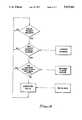
- FIG. 4is a flow diagram illustrating a basic PCA routine which may be performed by the main pump unit and cassette shown in FIGS. 1 through 3;
- FIG. 5is a perspective view of the security containment device of the present invention mounted on the main pump unit shown in FIGS. 1 and 2, which main pump unit contains the cassette shown in FIG. 3 mounted in drive bay C;
- FIG. 6is a sectional view of the security containment device shown in FIG. 5, showing the hinged lower housing opened for visibility;
- FIG. 7is a sectional view showing the interior of the lower housing of the security containment device.
- FIG. 8Ais a first sectional view of the lock mechanism of the security containment device in the locked position, holding the syringe tube mounted in place in the upper housing and preventing the latch from being operated to open the lower housing;
- FIG. 8Bis a second sectional view of the lock mechanism of the security containment device in the unlocked position, allowing the syringe tube to be removed from the upper housing and allowing the latch to be operated to open the lower housing;
- FIG. 9is a perspective view showing the side of the security containment device of the present invention which is mounted on the side of the main pump unit;
- FIG. 10is a perspective cutaway view of the security containment device of the present invention showing the hinged and spring-loaded syringe retainer shown in FIG. 10;
- FIG. 11is a top cutaway view of the security containment device of the present invention showing the syringe retainer
- FIG. 12is a sectional view showing a syringe located mounted in the security containment device of the present invention, which syringe is retained by the syringe retainer shown in FIGS. 10 and 11;
- FIG. 13is a perspective view of the syringe tube used with a short tube cap to hold a small plastic medicine bag.
- FIG. 14is a perspective view of the syringe tube used with a extended tube cap to hold a large syringe.
- a main pump unit 20is shown in FIGS. 1 and 2, and a disposable cassette 22 is shown in FIG. 3.
- the main pump unit 20has three bays for accepting up to three cassettes 22, with the bays being labeled A, B, and C.
- the bay labeled as Cis the position in which the cassette 22 will be inserted to be used as a PCA pump.
- the cassette 22contains a piston-type fluid pump and active valves to pump fluid, with the piston and valves in the cassette 22 being operated by a mechanical drive system located in and controlled by the main pump unit 20.
- the cassette 22has a slide latch 24 which serves both to lock the cassette 22 in place in one of the bays A, B, or C in the main pump unit 20, and to control the flow of fluid through the cassette 22.
- the cassette 22has an inlet tube 26 (shown in phantom lines) used to supply fluid to the cassette 22, and an outlet tube 28 (shown in phantom lines) used to carry fluid away from the cassette 22.
- the inlet and outlet tubes 26 and 28typically have luer connectors (not shown) on the ends thereof to provide for easy connection.
- the slide latch 24has two positions: a locked position in which it is flush with the front of the cassette 22, as shown in FIG. 3, and an unlocked position in which it is pulled back from the front of the cassette 22 (not shown). With the slide latch 24 pulled back from the front of the assembled cassette 22 in the unlocked position, an elongated, tear-shaped aperture 30 in the slide latch 24 will close the outlet tube 28, preventing fluid from flowing through the cassette 22.
- the inlet tube 26is connected to a fluid source such as an IV bag (not shown), and the outlet tube 28 is connected to a fluid delivery device such as an injection set (not shown), the use of which is well known in the art.
- the slide latch 24is moved to its locked position, and fluid fills the lines, the cassette 22, and the injection set. By tapping or shaking the cassette 22 any residual air bubbles will flow out through the line.
- the slide latch 24is then pulled back to its unlocked position to close the outlet tube 28, and the system is in a primed condition with the cassette 22 ready to be installed onto the main pump unit.
- the cassette 22With the rear-most edge of the cassette 22 tilted upward, the cassette 22 is inserted into bay C. When the cassette 22 is pushed fully back in place, the front of the cassette 22 is tilted upward. The slide latch 24 may then be pushed forward into its locked position. Simultaneously, the outlet tube 28 will be opened, but fluid will not flow through the outlet tube 28 since the cassette 22 is installed on the main pump unit 10. The cassette 22 will thus be held in position on the main pump unit 20 until the slide latch 24 is again pulled back to its unlocked position, releasing the cassette 22.
- the C channel in the main pump unit 20may be configured as a PCA pump, and a signal supplied to an input connector 32 on the main pump unit 20 may be used as the channel to actuate the pump at the patient's request.
- administrationis controlled by specifying demand dose volume (bolus volume), lockout interval (the minimum time between administration of doses, also called the refractory period), and maximum dosage over a given time period (four hours, for example). Additional commands which may optionally be utilized are a loading bolus (administered at the beginning of PCA therapy to quickly increase serum concentration of the drug) and continuous infusion (a basal rate to maintain an appropriate serum level, thereby minimizing the number of demand doses).
- the operation of a PCA deviceis shown in simplified fashion.
- the devicechecks to see if the lockout interval or refractory period has expired. If it has not, the device returns to the beginning of the loop to wait for a further bolus or demand dose request. This indicates that the patient has requested a demand dose too soon after the previous dose, with the relevant period being the lockout interval or refractory period set by the doctor.
- the devicechecks to see if the maximum cumulative dosage over the previous 4 hours (or other sliding window time period) would be exceeded by the bolus or demand dose requested. If the maximum cumulative dosage over the previous 4 hours would be exceeded by the bolus or demand dose requested, the device returns to the beginning of the loop to wait for a further bolus or demand dose request. This indicates that the patient has requested a cumulative dosage over the previous 4 hours which would exceed the maximum 4 hour dosage set by the doctor.
- the bolus or demand doseis administered to the patient.
- the devicethen returns to the beginning of the loop to wait for a further bolus or demand dose request.
- a bolus or demand doseis administered, the information stored on the lockout interval and the cumulative dosage over the previous 4 hours will be updated. If a loading bolus is used and/or continuous infusion is elected, the information on dosage administered will also be reflected in the information stored on the cumulative dosage over the previous 4 hours.
- the security containment device 40constituting the present invention is illustrated attached to the side of the main pump unit 20 adjacent bay C, in which the cassette 22 is mounted in a locked position.
- the security containment device 40includes an upper housing 42 and a lower housing 44, both of which are essentially rectangular in configuration.
- the upper housing 42includes a rectangular opening 46 on the top and near the back thereof, which opening 46 is to receive one of a plurality of interchangeable storage compartments, which will be described in detail below.
- the upper housing 42On the left side of the upper housing 42 is a horizontally extending U-shaped plate 48, which plate 48 is contoured to engage the right side of the main pump unit 20.
- the upper housing 42has a slot 50 located on the bottom of the left side thereof, as best shown in FIG. 9. The slot 50 is used to retain the upper housing 42, and the entire security containment device 40, in position on the main pump unit 20.
- the main pump unit 20is supported by a clamp fixture 52 (partially shown in FIG. 9) which is in turn locked to an IV pole 53 (shown in phantom lines in FIG. 1) by the use of the clamp device described in the above-identified incorporated by reference patent application entitled “Clamp Fixture.”
- the clamp fixture 52is normally secured to the main pump unit 20 by bolts (not shown) screwed into threaded apertures 54 and 56 (FIGS. 1 and 2) in the main pump unit 20.
- the security containment device 40uses instead of the standard bolt screwed into the threaded aperture 54 (FIG. 2) on the right side of the main pump unit 20 a bolt having a knob 58 mounted thereon, as shown in FIG. 9.
- the slot 50 in the upper housing 42is placed over the shaft of the knob 58, and the knob 58 is turned to screw into the main pump unit 20, thus securing both the upper housing 42 and the clamp fixture 52 therebetween, as best shown in FIG. 6.
- the knob 58will be secured inside the upper and lower housings 42 and 44, thus securing the assembly including the main pump unit 20, the security containment device 40, and the clamp fixture 52 together. Since the clamp fixture 52 may be locked onto an IV pole 53, securing the upper housing 42 to the lower housing 44 will accordingly secure the main pump unit 20 and the security containment device 40 to the IV pole 53.
- the lower housing 44is hingedly attached at the back thereof to the back of the upper housing 42, in a manner allowing the lower housing 44 to swing down when released.
- the upper housing 42has an aperture 60 located at the front and top thereof, which aperture 60 has a latch member 62 mounted therein.
- the latch member 62is hingedly mounted at the top thereof to the interior of the upper housing 42.
- a spring 64biases the latch member 62 outwardly to a position essentially flush with the exterior of the upper housing 42.
- the latch member 62has at the bottom thereof a tapered catch 66, which is designed to cooperated with a notch 68 in the interior of and at the top and front of the lower housing 44.
- the lower housing 44has a notch 72 located on the left side near the front thereof.
- the notch 72allows a segment of tubing to extend from the interior of the upper and lower housings 42 and 44 to the cassette 22. This segment of tubing would be the inlet tube 26 leading to the cassette 22.
- the inlet tube 26would be protected by the configuration of the U-shaped extension 70 from the left side of the lower housing 44, which U-shaped extension 70 fits closely over the right bottom portion of the main pump unit 20.
- the security containment device 40thus protects the integrity of the fluid line between the medication reservoir and the cassette 22, thereby preventing the fluid line from being breached between the medication reservoir and the cassette and draining the medication reservoir.
- a key-type lock 74is located in the top of the upper housing 42, which lock 74 may be operated by a key 76.
- the lock 74operates a first arm 78 and a second arm 80, both of which arms 78 and 80 are mounted onto the bottom of a shaft turned by the lock 74 inside the upper housing 42.
- the arms 78 and 80are mounted on the lock 74 180 degrees apart, and the lock 74 may turn 90 degrees from a locked position to an unlocked position.
- the locked positionthe first arm 78 is directed toward the front of the security containment device 40, and the second arm 80 is directed toward the rear.
- first arm 78is directed toward the left side of the security containment device 40, and the second arm 80 is directed toward the right side.
- the lock 74In the locked position, the first arm 78 bears against the latch member 62, preventing it from being pressed inwardly to release the lower housing 44.
- the lock 74When the lock 74 is turned to the unlocked position, the first arm 78 moves away from the latch member 62, allowing it to be pressed inwardly to release the lower housing 44.
- the first arm 78In the unlocked position, the first arm 78 bears against the knob 58, preventing it from being turned.
- the lock 74To turn the knob 58 to release the security containment device 40 from the main pump unit 20, the lock 74 must be returned to its locked position after the lower housing 44 is opened and with the lower housing 44 remaining open.
- a slot 82is located in the front wall defining the opening 46 in the upper housing 42, as best shown in FIGS. 6, 8A, and 8B.
- the slot 82allows the second arm 80 to move therein as it is turned from a unlocked position to a locked position.
- the locked position shown in phantom lines in FIG. 6,it should be noted that the second arm 80 extends beyond the back of the front wall defining the opening 46 into the opening 46. This will function to retain the chosen medication storage compartment, as will become evident below.
- a switch 84Also located in the upper housing 42 as shown in FIG. 6 is a switch 84.
- the switch 84When the first arm 78 is moved by the lock 74 from the unlocked position to the locked position, the switch 84 will close.
- the switch 84is connected by a wire 86 to a cable 88, which leads to a connector 90 which may in turn be plugged into the input connector 32 on the main pump unit 20.
- the security containment device 40will prevent the main pump unit 20 from delivering medication unless the switch 84 has closed to indicate the security containment device 40 has been locked.
- Actuation of the switch 84 indicating that the security containment device 40 is lockedalso serves to prevent further settings from being made for the infusion parameters for channel C of the security containment device 40.
- the switch 84may optionally be a momentary contact switch which closes for a moment when contacted by the first arm 78.
- a plug 96 on a removeable actuation cable 98is removably plugged into the socket 94 to connect the removeable actuation cable 98 to the security containment device 40.
- a switch 100is located at the end of the removeable actuation cable 98 opposite the plug 96, and the switch may be actuated by a patient to request a demand dose or bolus.
- the removeable actuation cable 98is of sufficient length to reach a patient, so that the patient need only squeeze a button 102 on the switch 100 to request a demand dose or bolus.
- a syringe retainer 104 mounted inside 42is illustrated.
- the syringe retainer 104is hingeably mounted together with the lower housing 44 on the lower back of the upper housing 44.
- a spring 106is used to bias the syringe retainer 104 upwardly.
- the syringe retainer 104is U-shaped, and is hingeably mounted on the bottom of the U.
- the upper leg of the Uis shorter than is the lower leg.
- the upper leg of the Uis a rectangular plate 108 fitting in the bottom of the opening 46 in the upper housing 42.
- the rectangular plate 108has a notch 110 therein from the front, the notch 110 being to accommodate and support the end of a syringe 111 (FIG. 12) having a luer connector thereon.
- the lower leg of the Uhas an aperture 112 therein, which aperture 112 is disposed near the bottom of the U and extends longitudinally in the lower leg of the U.
- the aperture 112is to allow the inlet tube 26 to extend downward from the syringe 111 to the interior of the lower housing 44, from which it exits through the notch 72 (FIG. 8B) toward the cassette 22.
- the security containment device 40is intended to accommodate a variety of interchangeable storage compartments, all of which have a rectangular cross-section and fit in the opening 46.
- a rectangular syringe tube 120the bottom of which is shown in FIG. 12.
- An indentation 122 in the bottom of the rectangular syringe tube 120is aligned with the slot 82 in the front of the opening 46 in the upper housing 42 when the rectangular syringe tube 120 is inserted fully into the opening 46.
- the second arm 80will move into the indentation 122 in the rectangular syringe tube 120 when the lock 74 is moved to the locked position, securing the rectangular syringe tube 120 to the security containment device 40.
- All interchangeable storage compartmentshave such an indentation 122, thereby allowing them to be locked to the security containment device 40 to secure medication contained therein.
- the storage compartmentsmay use one-way snap locks which can only be released from the device when the security containment device is unlocked and released from the inside.
- snap locksare well known in the art.
- the rectangular syringe tube 120is shown with a long end cap 126, which would be adhesively and permanently attached to the rectangular syringe tube 120.
- the combination of the rectangular syringe tube 120 and the long end cap 126allow a large syringe 111 to fit therein with the plunger fully extended. If a smaller syringe (not shown) is to be used, a short end cap 128 as shown in FIG. 13 may be used.
- a bag tube 132is used in conjunction with the short end cap 128.
- a needle 134is attached to the inlet tube 26, and the needle 134 may be inserted into the plastic medication bag 130. Note that all storage compartments used in conjunction with the security containment device 40 will be open only at the end inserted into the opening 46 in the upper housing 42, and that the indentation 122 is present to allow each of the storage compartments to be locked to the security containment device 40.
- Installation of the security containment device 40 onto the main pump unit 20is quick and convenient.
- the knob 58is first substituted for the standard bolt on the right side of the main pump unit 20.
- the lock 74is turned to the unlocked position, the lower housing 44 is opened, and the lock 74 is returned to the locked position.
- the slot 50 in the upper housing 42is placed over the shaft of the knob 58, and the knob 58 is tightened.
- the lock 74is then turned again to the unlocked position.
- the connector 90is plugged into the input connector 32 on the main pump unit 20, and the plug 96 on the removeable actuation cable 98 is plugged into the socket 94.
- the inlet tube 26 from the cassette 22is threaded through the aperture 112 and the notch 110 in the syringe retainer 104.
- the desired medication reservoir deviceis installed into the corresponding storage compartment, the inlet tube 26 is attached to the medication reservoir device, and the storage compartment is inserted fully into the opening 46 in the upper housing 42.
- the cassette 22may then be primed and installed onto the main pump unit 20.
- the lower housing 44is then closed with the inlet tube 26 extending through the notch 72 in the lower housing 44.
- the lock 74is turned to the locked position.
- the security containment device 40is properly installed, and the PCA system is ready to be utilized.
- the latch member 62 and the spring 64may be deleted by lowering the position of the first arm 78 to the level of the notch 68 in the lower housing 44. It will be appreciated in this case that the first arm 78 will cooperate with the notch 68 in the lower housing 44 to hold the lower housing 44 in a closed position when the lock 74 is in the locked position. When the lock 74 is turned to an unlocked position, the first arm 78 will move out of the notch 68 in the lower housing 44, immediately releasing the lower housing 44 and allowing it to open.
- the present inventionprovides a mechanism for securing the supply of medication in the reservoir located near the PCA pump.
- the reservoiris secured to the PCA pump to prevent it from being stolen or removed.
- the present inventionby securing the medication to the main pump unit effectively prevents its theft or removal.
- the system of the present inventionalso protects the integrity of the fluid line between the medication reservoir and the cassette, thereby preventing an unauthorized individual from breaching the fluid line between the medication reservoir and the cassette and draining the medication reservoir.
- the present inventionprevents the unauthorized removal of the cassette from the main pump unit, thus also preventing a potentially deadly free flow condition through the cassette from occurring.
- the security provisions of the present inventionthereby prevent both action by a patient or tampering by an unauthorized individual from violating the security of the medication being administered.
- the security attachment of the present inventionis compact in size, inexpensive to manufacture, and yet will accommodate any of the several different sizes and configurations of medication containers, including various size syringes and small flexible plastic bags.
- the system of the present inventionaccomplishes all of the aforesaid objectives and advantages without incurring any relative disadvantage.
Landscapes
- Health & Medical Sciences (AREA)
- Vascular Medicine (AREA)
- Engineering & Computer Science (AREA)
- Anesthesiology (AREA)
- Biomedical Technology (AREA)
- Heart & Thoracic Surgery (AREA)
- Hematology (AREA)
- Life Sciences & Earth Sciences (AREA)
- Animal Behavior & Ethology (AREA)
- General Health & Medical Sciences (AREA)
- Public Health (AREA)
- Veterinary Medicine (AREA)
- Infusion, Injection, And Reservoir Apparatuses (AREA)
Abstract
Description
Claims (24)
Priority Applications (5)
| Application Number | Priority Date | Filing Date | Title |
|---|---|---|---|
| US07/279,466US5009641A (en) | 1988-12-02 | 1988-12-02 | Patient-controlled analgesia security attachment for a medication infusion system |
| CA002001942ACA2001942C (en) | 1988-12-02 | 1989-11-01 | Patient-controlled analgesia security attachment for a medication infusion system |
| DE68916196TDE68916196T2 (en) | 1988-12-02 | 1989-12-01 | Patient controlled analgesia safety attachment for a drug infusion system. |
| EP89312579AEP0372863B1 (en) | 1988-12-02 | 1989-12-01 | Patient-controlled analgesia security attachment for a medication infusion system |
| JP1314129AJPH02264666A (en) | 1988-12-02 | 1989-12-02 | Safe accessary for medicine injector of patient controlled painless method |
Applications Claiming Priority (1)
| Application Number | Priority Date | Filing Date | Title |
|---|---|---|---|
| US07/279,466US5009641A (en) | 1988-12-02 | 1988-12-02 | Patient-controlled analgesia security attachment for a medication infusion system |
Publications (1)
| Publication Number | Publication Date |
|---|---|
| US5009641Atrue US5009641A (en) | 1991-04-23 |
Family
ID=23069086
Family Applications (1)
| Application Number | Title | Priority Date | Filing Date |
|---|---|---|---|
| US07/279,466Expired - LifetimeUS5009641A (en) | 1988-12-02 | 1988-12-02 | Patient-controlled analgesia security attachment for a medication infusion system |
Country Status (5)
| Country | Link |
|---|---|
| US (1) | US5009641A (en) |
| EP (1) | EP0372863B1 (en) |
| JP (1) | JPH02264666A (en) |
| CA (1) | CA2001942C (en) |
| DE (1) | DE68916196T2 (en) |
Cited By (39)
| Publication number | Priority date | Publication date | Assignee | Title |
|---|---|---|---|---|
| WO1993005829A1 (en)* | 1991-09-26 | 1993-04-01 | Baxter International Inc. | Intravenous tube safety apparatus |
| WO1993012828A1 (en)* | 1991-12-20 | 1993-07-08 | Abbott Laboratories | Drug channel identification and security system for infusion and pumping systems |
| US5449347A (en)* | 1994-07-05 | 1995-09-12 | The United States Of America As Represented By The Secretary Of The Air Force | Patient transport, plural power source suction apparatus |
| US5683367A (en)* | 1995-03-06 | 1997-11-04 | Sabratek Corporation | Infusion pump with different operating modes |
| US5772635A (en)* | 1995-05-15 | 1998-06-30 | Alaris Medical Systems, Inc. | Automated infusion system with dose rate calculator |
| US5800396A (en)* | 1995-11-15 | 1998-09-01 | Alcon Laboratories, Inc. | Surgical cassette adapter |
| US6126642A (en)* | 1998-10-02 | 2000-10-03 | Science Incorporated | Patient controlled fluid delivery device |
| US6221045B1 (en)* | 1995-04-20 | 2001-04-24 | Acist Medical Systems, Inc. | Angiographic injector system with automatic high/low pressure switching |
| US6276567B1 (en) | 1999-03-29 | 2001-08-21 | Hydrus, Inc. | Pressurized fluid delivery apparatus |
| US20020175062A1 (en)* | 2001-05-03 | 2002-11-28 | Philip Etter | Switching device for a pump for administering a fluid for detecting the switching device |
| US20020183693A1 (en)* | 1992-09-09 | 2002-12-05 | Sims Deltec, Inc. | Drug pump systems and methods |
| US6516749B1 (en) | 1999-06-18 | 2003-02-11 | Salasoft, Inc. | Apparatus for the delivery to an animal of a beneficial agent |
| US6585683B2 (en)* | 2001-09-19 | 2003-07-01 | Advanced Medical Optics, Inc. | Tubing management manifold with tubing captures |
| USD479324S1 (en) | 2002-07-23 | 2003-09-02 | Baxter International Inc | Push button |
| US20060093785A1 (en)* | 1998-06-03 | 2006-05-04 | Scott Laboratories, Inc. | Apparatus, method and drug products for providing a conscious patient relief from pain and anxiety associated with medical or surgical procedures |
| US7530968B2 (en) | 2003-04-23 | 2009-05-12 | Valeritas, Inc. | Hydraulically actuated pump for long duration medicament administration |
| US7914499B2 (en) | 2006-03-30 | 2011-03-29 | Valeritas, Inc. | Multi-cartridge fluid delivery device |
| US8133197B2 (en) | 2008-05-02 | 2012-03-13 | Smiths Medical Asd, Inc. | Display for pump |
| US8149131B2 (en) | 2006-08-03 | 2012-04-03 | Smiths Medical Asd, Inc. | Interface for medical infusion pump |
| US20120209241A1 (en)* | 2011-02-10 | 2012-08-16 | Medtronic, Inc. | Medical fluid delivery device programming |
| US8250483B2 (en) | 2002-02-28 | 2012-08-21 | Smiths Medical Asd, Inc. | Programmable medical infusion pump displaying a banner |
| US20130001180A1 (en)* | 2011-06-29 | 2013-01-03 | Stout Christopher A | Sterile rack for contraceptive procedure |
| US8435206B2 (en) | 2006-08-03 | 2013-05-07 | Smiths Medical Asd, Inc. | Interface for medical infusion pump |
| US8504179B2 (en) | 2002-02-28 | 2013-08-06 | Smiths Medical Asd, Inc. | Programmable medical infusion pump |
| US20140114283A1 (en)* | 2012-10-23 | 2014-04-24 | Cory Congleton | Nurse controlled access of medication pump |
| US8858526B2 (en) | 2006-08-03 | 2014-10-14 | Smiths Medical Asd, Inc. | Interface for medical infusion pump |
| US8954336B2 (en) | 2004-02-23 | 2015-02-10 | Smiths Medical Asd, Inc. | Server for medical device |
| US8965707B2 (en) | 2006-08-03 | 2015-02-24 | Smiths Medical Asd, Inc. | Interface for medical infusion pump |
| US9089636B2 (en) | 2004-07-02 | 2015-07-28 | Valeritas, Inc. | Methods and devices for delivering GLP-1 and uses thereof |
| US20160206833A1 (en)* | 2010-07-22 | 2016-07-21 | Medical Flow Systems Ltd | Pulse infusion device system and method |
| US20180028744A1 (en)* | 2015-02-27 | 2018-02-01 | E-Wha Meditech Inc. | Medical fluid injector and medical fluid supply device including same |
| US9932977B2 (en) | 2012-10-15 | 2018-04-03 | Smiths Medical Asd, Inc. | Infusion system disposable alignment system |
| US10086137B2 (en) | 2010-07-22 | 2018-10-02 | Medical Flow Systems Ltd | Pulse infusion device system and method |
| US10682460B2 (en) | 2013-01-28 | 2020-06-16 | Smiths Medical Asd, Inc. | Medication safety devices and methods |
| USD914197S1 (en)* | 2018-08-16 | 2021-03-23 | Deka Products Limited Partnership | Syringe pump |
| USD914195S1 (en)* | 2018-08-16 | 2021-03-23 | Deka Products Limited Partnership | Syringe pump |
| USD954968S1 (en) | 2018-08-16 | 2022-06-14 | Deka Products Limited Partnership | Central controller |
| US20220304824A1 (en)* | 2019-03-07 | 2022-09-29 | Spinal Surgical Strategies, Inc., A Nevada Corporation D/B/A Kleiner Device Labs | Bone graft delivery system and method for using same |
| USD1055978S1 (en) | 2018-08-16 | 2024-12-31 | Deka Products Limited Partnership | Peristaltic pump |
Families Citing this family (7)
| Publication number | Priority date | Publication date | Assignee | Title |
|---|---|---|---|---|
| US5537289A (en)* | 1994-03-11 | 1996-07-16 | Spacelabs Medical, Inc. | Wall-mounted medical monitoring system with removable modules |
| GB9724223D0 (en) | 1997-11-18 | 1998-01-14 | Pa Consulting Services | Drug delivery device |
| US6056522A (en)* | 1998-05-13 | 2000-05-02 | Sims Deltec, Inc. | Reusable cassette with a moveable door |
| BR9909316A (en)* | 1999-02-01 | 2000-11-21 | Baxter Int | Set for intravascular administration, intravascular infusion pump, and, intravascular fluid infusion process to a patient |
| AUPP863599A0 (en)* | 1999-02-12 | 1999-03-04 | Cade, John F. | Method of, and apparatus for, controlling the delivery of a medication |
| DE10303512B4 (en)* | 2003-01-30 | 2005-12-22 | Mathias Nietzke | Medical treatment system, esp. Infusion device, with a plurality of addition tubing with flow barriers and suitable safety hose clamp |
| US20060042631A1 (en)* | 2004-08-31 | 2006-03-02 | Martin James F | Apparatus to deliver oxygen to a patient |
Citations (15)
| Publication number | Priority date | Publication date | Assignee | Title |
|---|---|---|---|---|
| US3731679A (en)* | 1970-10-19 | 1973-05-08 | Sherwood Medical Ind Inc | Infusion system |
| US3927955A (en)* | 1971-08-23 | 1975-12-23 | East West Medical Products Inc | Medical cassette pump |
| US4187057A (en)* | 1978-01-11 | 1980-02-05 | Stewart-Naumann Laboratories, Inc. | Peristaltic infusion pump and disposable cassette for use therewith |
| US4314567A (en)* | 1979-09-24 | 1982-02-09 | Imed Corporation | Drop controller |
| WO1982003254A1 (en)* | 1981-03-13 | 1982-09-30 | Baxter Travenol Lab | Miniature rotary infusion pump with slide latch and detachable power source |
| US4447234A (en)* | 1981-04-10 | 1984-05-08 | Parker-Hannifin Corporation | Medication infusion pump |
| US4468222A (en)* | 1976-05-24 | 1984-08-28 | Valleylab | Intravenous liquid pumping system and method |
| US4479761A (en)* | 1982-12-28 | 1984-10-30 | Baxter Travenol Laboratories, Inc. | Actuator apparatus for a prepackaged fluid processing module having pump and valve elements operable in response to externally applied pressures |
| US4496351A (en)* | 1982-04-05 | 1985-01-29 | Ipco Corporation | Infusion monitor |
| US4565542A (en)* | 1984-10-19 | 1986-01-21 | Deltec Systems, Inc. | Locking mechanism for a drug delivery system |
| GB2165312A (en)* | 1984-10-02 | 1986-04-09 | Plastina Sa | Portable self-contained injector for perfusions |
| US4627839A (en)* | 1985-11-21 | 1986-12-09 | American Hospital Supply Corporation | Patient controlled analgesia conversion |
| US4653987A (en)* | 1984-07-06 | 1987-03-31 | Tsuyoshi Tsuji | Finger peristaltic infusion pump |
| US4688545A (en)* | 1985-07-31 | 1987-08-25 | Patterson Tom W | Stove |
| US4756706A (en)* | 1985-01-23 | 1988-07-12 | American Hospital Supply Corporation | Centrally managed modular infusion pump system |
Family Cites Families (1)
| Publication number | Priority date | Publication date | Assignee | Title |
|---|---|---|---|---|
| DE3581704D1 (en)* | 1984-10-19 | 1991-03-14 | Pharmacia Deltec Inc | MEDICINE DISPENSING SYSTEM. |
- 1988
- 1988-12-02USUS07/279,466patent/US5009641A/ennot_activeExpired - Lifetime
- 1989
- 1989-11-01CACA002001942Apatent/CA2001942C/ennot_activeExpired - Fee Related
- 1989-12-01DEDE68916196Tpatent/DE68916196T2/ennot_activeExpired - Fee Related
- 1989-12-01EPEP89312579Apatent/EP0372863B1/ennot_activeExpired - Lifetime
- 1989-12-02JPJP1314129Apatent/JPH02264666A/enactivePending
Patent Citations (15)
| Publication number | Priority date | Publication date | Assignee | Title |
|---|---|---|---|---|
| US3731679A (en)* | 1970-10-19 | 1973-05-08 | Sherwood Medical Ind Inc | Infusion system |
| US3927955A (en)* | 1971-08-23 | 1975-12-23 | East West Medical Products Inc | Medical cassette pump |
| US4468222A (en)* | 1976-05-24 | 1984-08-28 | Valleylab | Intravenous liquid pumping system and method |
| US4187057A (en)* | 1978-01-11 | 1980-02-05 | Stewart-Naumann Laboratories, Inc. | Peristaltic infusion pump and disposable cassette for use therewith |
| US4314567A (en)* | 1979-09-24 | 1982-02-09 | Imed Corporation | Drop controller |
| WO1982003254A1 (en)* | 1981-03-13 | 1982-09-30 | Baxter Travenol Lab | Miniature rotary infusion pump with slide latch and detachable power source |
| US4447234A (en)* | 1981-04-10 | 1984-05-08 | Parker-Hannifin Corporation | Medication infusion pump |
| US4496351A (en)* | 1982-04-05 | 1985-01-29 | Ipco Corporation | Infusion monitor |
| US4479761A (en)* | 1982-12-28 | 1984-10-30 | Baxter Travenol Laboratories, Inc. | Actuator apparatus for a prepackaged fluid processing module having pump and valve elements operable in response to externally applied pressures |
| US4653987A (en)* | 1984-07-06 | 1987-03-31 | Tsuyoshi Tsuji | Finger peristaltic infusion pump |
| GB2165312A (en)* | 1984-10-02 | 1986-04-09 | Plastina Sa | Portable self-contained injector for perfusions |
| US4565542A (en)* | 1984-10-19 | 1986-01-21 | Deltec Systems, Inc. | Locking mechanism for a drug delivery system |
| US4756706A (en)* | 1985-01-23 | 1988-07-12 | American Hospital Supply Corporation | Centrally managed modular infusion pump system |
| US4688545A (en)* | 1985-07-31 | 1987-08-25 | Patterson Tom W | Stove |
| US4627839A (en)* | 1985-11-21 | 1986-12-09 | American Hospital Supply Corporation | Patient controlled analgesia conversion |
Cited By (74)
| Publication number | Priority date | Publication date | Assignee | Title |
|---|---|---|---|---|
| WO1993005829A1 (en)* | 1991-09-26 | 1993-04-01 | Baxter International Inc. | Intravenous tube safety apparatus |
| US5290239A (en)* | 1991-09-26 | 1994-03-01 | Baxter International, Inc. | Intravenous tube safety apparatus |
| AU656035B2 (en)* | 1991-09-26 | 1995-01-19 | Baxter International Inc. | Intravenous tube safety apparatus |
| WO1993012828A1 (en)* | 1991-12-20 | 1993-07-08 | Abbott Laboratories | Drug channel identification and security system for infusion and pumping systems |
| US5445621A (en)* | 1991-12-20 | 1995-08-29 | Abbott Laboratories | Drug identification and security apparatus for infusion and pumping systems |
| US7347836B2 (en) | 1992-09-09 | 2008-03-25 | Smiths Medical, Inc. | Drug pump systems and methods |
| US20020183693A1 (en)* | 1992-09-09 | 2002-12-05 | Sims Deltec, Inc. | Drug pump systems and methods |
| US7654976B2 (en) | 1992-09-09 | 2010-02-02 | Smiths Medical Asd, Inc. | Drug pump systems and methods |
| US5449347A (en)* | 1994-07-05 | 1995-09-12 | The United States Of America As Represented By The Secretary Of The Air Force | Patient transport, plural power source suction apparatus |
| US5683367A (en)* | 1995-03-06 | 1997-11-04 | Sabratek Corporation | Infusion pump with different operating modes |
| US6221045B1 (en)* | 1995-04-20 | 2001-04-24 | Acist Medical Systems, Inc. | Angiographic injector system with automatic high/low pressure switching |
| US5772635A (en)* | 1995-05-15 | 1998-06-30 | Alaris Medical Systems, Inc. | Automated infusion system with dose rate calculator |
| US5800396A (en)* | 1995-11-15 | 1998-09-01 | Alcon Laboratories, Inc. | Surgical cassette adapter |
| US20060093785A1 (en)* | 1998-06-03 | 2006-05-04 | Scott Laboratories, Inc. | Apparatus, method and drug products for providing a conscious patient relief from pain and anxiety associated with medical or surgical procedures |
| US6126642A (en)* | 1998-10-02 | 2000-10-03 | Science Incorporated | Patient controlled fluid delivery device |
| US6401975B2 (en) | 1999-03-29 | 2002-06-11 | Hydrus, Inc. | Pressurized fluid delivery apparatus |
| US6276567B1 (en) | 1999-03-29 | 2001-08-21 | Hydrus, Inc. | Pressurized fluid delivery apparatus |
| US6516749B1 (en) | 1999-06-18 | 2003-02-11 | Salasoft, Inc. | Apparatus for the delivery to an animal of a beneficial agent |
| US20020175062A1 (en)* | 2001-05-03 | 2002-11-28 | Philip Etter | Switching device for a pump for administering a fluid for detecting the switching device |
| US6585683B2 (en)* | 2001-09-19 | 2003-07-01 | Advanced Medical Optics, Inc. | Tubing management manifold with tubing captures |
| US8504179B2 (en) | 2002-02-28 | 2013-08-06 | Smiths Medical Asd, Inc. | Programmable medical infusion pump |
| US8250483B2 (en) | 2002-02-28 | 2012-08-21 | Smiths Medical Asd, Inc. | Programmable medical infusion pump displaying a banner |
| USD479324S1 (en) | 2002-07-23 | 2003-09-02 | Baxter International Inc | Push button |
| US10525194B2 (en) | 2003-04-23 | 2020-01-07 | Valeritas, Inc. | Hydraulically actuated pump for fluid administration |
| US7530968B2 (en) | 2003-04-23 | 2009-05-12 | Valeritas, Inc. | Hydraulically actuated pump for long duration medicament administration |
| US11642456B2 (en) | 2003-04-23 | 2023-05-09 | Mannkind Corporation | Hydraulically actuated pump for fluid administration |
| US8070726B2 (en) | 2003-04-23 | 2011-12-06 | Valeritas, Inc. | Hydraulically actuated pump for long duration medicament administration |
| US9125983B2 (en) | 2003-04-23 | 2015-09-08 | Valeritas, Inc. | Hydraulically actuated pump for fluid administration |
| US9072828B2 (en) | 2003-04-23 | 2015-07-07 | Valeritas, Inc. | Hydraulically actuated pump for long duration medicament administration |
| US9511187B2 (en) | 2003-04-23 | 2016-12-06 | Valeritas, Inc. | Hydraulically actuated pump for fluid administration |
| US8954336B2 (en) | 2004-02-23 | 2015-02-10 | Smiths Medical Asd, Inc. | Server for medical device |
| US9089636B2 (en) | 2004-07-02 | 2015-07-28 | Valeritas, Inc. | Methods and devices for delivering GLP-1 and uses thereof |
| US20110137287A1 (en)* | 2006-03-30 | 2011-06-09 | Valeritas, Inc. | Multi-cartridge fluid delivery device |
| US9687599B2 (en) | 2006-03-30 | 2017-06-27 | Valeritas, Inc. | Multi-cartridge fluid delivery device |
| US8821443B2 (en) | 2006-03-30 | 2014-09-02 | Valeritas, Inc. | Multi-cartridge fluid delivery device |
| US8361053B2 (en) | 2006-03-30 | 2013-01-29 | Valeritas, Inc. | Multi-cartridge fluid delivery device |
| US10493199B2 (en) | 2006-03-30 | 2019-12-03 | Valeritas, Inc. | Multi-cartridge fluid delivery device |
| US7914499B2 (en) | 2006-03-30 | 2011-03-29 | Valeritas, Inc. | Multi-cartridge fluid delivery device |
| US12246159B2 (en) | 2006-03-30 | 2025-03-11 | Mannkind Corporation | Multi-cartridge fluid delivery device |
| US8858526B2 (en) | 2006-08-03 | 2014-10-14 | Smiths Medical Asd, Inc. | Interface for medical infusion pump |
| US10255408B2 (en) | 2006-08-03 | 2019-04-09 | Smiths Medical Asd, Inc. | Interface for medical infusion pump |
| US8952794B2 (en) | 2006-08-03 | 2015-02-10 | Smiths Medical Asd, Inc. | Interface for medical infusion pump |
| US10437963B2 (en) | 2006-08-03 | 2019-10-08 | Smiths Medical Asd, Inc. | Interface for medical infusion pump |
| US8965707B2 (en) | 2006-08-03 | 2015-02-24 | Smiths Medical Asd, Inc. | Interface for medical infusion pump |
| US8435206B2 (en) | 2006-08-03 | 2013-05-07 | Smiths Medical Asd, Inc. | Interface for medical infusion pump |
| US9740829B2 (en) | 2006-08-03 | 2017-08-22 | Smiths Medical Asd, Inc. | Interface for medical infusion pump |
| US8149131B2 (en) | 2006-08-03 | 2012-04-03 | Smiths Medical Asd, Inc. | Interface for medical infusion pump |
| US11580918B2 (en) | 2008-05-02 | 2023-02-14 | Tandem Diabetes Care, Inc. | Display for pump |
| US8133197B2 (en) | 2008-05-02 | 2012-03-13 | Smiths Medical Asd, Inc. | Display for pump |
| US11488549B2 (en) | 2008-05-02 | 2022-11-01 | Tandem Diabetes Care, Inc. | Display for pump |
| US10726100B2 (en) | 2008-05-02 | 2020-07-28 | Tandem Diabetes Care, Inc. | Display for pump |
| US10086137B2 (en) | 2010-07-22 | 2018-10-02 | Medical Flow Systems Ltd | Pulse infusion device system and method |
| US10279129B2 (en)* | 2010-07-22 | 2019-05-07 | Medical Flow System Ltd. | Pulse infusion device system and method |
| US20160206833A1 (en)* | 2010-07-22 | 2016-07-21 | Medical Flow Systems Ltd | Pulse infusion device system and method |
| US10780221B2 (en) | 2010-07-22 | 2020-09-22 | Medical Flow Systems Ltd. | Pulse infusion device system and method |
| US10719584B2 (en)* | 2011-02-10 | 2020-07-21 | Medtronic, Inc. | Medical fluid delivery device programming |
| US20120209241A1 (en)* | 2011-02-10 | 2012-08-16 | Medtronic, Inc. | Medical fluid delivery device programming |
| US20210012874A1 (en)* | 2011-02-10 | 2021-01-14 | Medtronic, Inc. | Medical fluid delivery device programming |
| US11986625B2 (en)* | 2011-02-10 | 2024-05-21 | Medtronic, Inc. | Medical fluid delivery device programming |
| US20130001180A1 (en)* | 2011-06-29 | 2013-01-03 | Stout Christopher A | Sterile rack for contraceptive procedure |
| US9932977B2 (en) | 2012-10-15 | 2018-04-03 | Smiths Medical Asd, Inc. | Infusion system disposable alignment system |
| US20140114283A1 (en)* | 2012-10-23 | 2014-04-24 | Cory Congleton | Nurse controlled access of medication pump |
| US10881784B2 (en) | 2013-01-28 | 2021-01-05 | Smiths Medical Asd, Inc. | Medication safety devices and methods |
| US10682460B2 (en) | 2013-01-28 | 2020-06-16 | Smiths Medical Asd, Inc. | Medication safety devices and methods |
| US10493200B2 (en)* | 2015-02-27 | 2019-12-03 | E-Wha Meditech Inc. | Medical fluid injector and medical fluid supply device including same |
| US20180028744A1 (en)* | 2015-02-27 | 2018-02-01 | E-Wha Meditech Inc. | Medical fluid injector and medical fluid supply device including same |
| USD1021072S1 (en) | 2018-08-16 | 2024-04-02 | Deka Products Limited Partnership | Syringe pump |
| USD954968S1 (en) | 2018-08-16 | 2022-06-14 | Deka Products Limited Partnership | Central controller |
| USD1021073S1 (en) | 2018-08-16 | 2024-04-02 | Deka Products Limited Partnership | Syringe pump |
| USD914195S1 (en)* | 2018-08-16 | 2021-03-23 | Deka Products Limited Partnership | Syringe pump |
| USD1055978S1 (en) | 2018-08-16 | 2024-12-31 | Deka Products Limited Partnership | Peristaltic pump |
| USD1063078S1 (en) | 2018-08-16 | 2025-02-18 | Deka Products Limited Partnership | Handle of a central controller |
| USD914197S1 (en)* | 2018-08-16 | 2021-03-23 | Deka Products Limited Partnership | Syringe pump |
| US20220304824A1 (en)* | 2019-03-07 | 2022-09-29 | Spinal Surgical Strategies, Inc., A Nevada Corporation D/B/A Kleiner Device Labs | Bone graft delivery system and method for using same |
Also Published As
| Publication number | Publication date |
|---|---|
| EP0372863A2 (en) | 1990-06-13 |
| DE68916196D1 (en) | 1994-07-21 |
| EP0372863B1 (en) | 1994-06-15 |
| CA2001942A1 (en) | 1990-06-02 |
| CA2001942C (en) | 1995-11-14 |
| DE68916196T2 (en) | 1995-01-19 |
| EP0372863A3 (en) | 1990-10-10 |
| JPH02264666A (en) | 1990-10-29 |
Similar Documents
| Publication | Publication Date | Title |
|---|---|---|
| US5009641A (en) | Patient-controlled analgesia security attachment for a medication infusion system | |
| JP3203006B2 (en) | Chemical injection pump with two-position syringe positioning means | |
| US5131816A (en) | Cartridge fed programmable ambulatory infusion pumps powered by DC electric motors | |
| US4627839A (en) | Patient controlled analgesia conversion | |
| US4857056A (en) | Auto-flush syringe pump | |
| NL194604C (en) | Implantable drug pump system. | |
| US4608042A (en) | Apparatus for sequential infusion of medical solutions | |
| EP1581288B1 (en) | Patient controlled drug administration device | |
| EP0592483B2 (en) | Apparatus for patient-controlled infusion | |
| ES2534781T3 (en) | Enhanced device for administering medications with a patient-controlled high-volume bolus | |
| EP2387428B1 (en) | Reservoir compartment adapter for infusion device | |
| US4828551A (en) | Patient controlled analgesia apparatus | |
| US6010483A (en) | Patient controlled analgesia device for use with ultrashort acting opioid medication and method for using the same | |
| EP3655065A2 (en) | Housing arrangements for infusion pumps | |
| US20250205419A1 (en) | Systems and methods for syringe handling | |
| JPS63501195A (en) | Device for patient-controlled release of beneficial drugs | |
| US9504629B2 (en) | Medication dispensers | |
| US6500156B1 (en) | Thumb-powered flushing device for catheters | |
| US4759527A (en) | Infusion pump valve | |
| EP3436112B1 (en) | Pulse infusion device system and method | |
| EP3055002B1 (en) | Large-volume bolus patient controlled drug administration device with lock-out | |
| US6730060B1 (en) | Implantable device for administering a treatment solution and operating device for a syringe for filling the device | |
| US20070255236A1 (en) | Implantable therapeutic substance delivery system with catheter access port block and method of use | |
| White | Patient-Controlled Analgesia (Part I): Historical Perspective | |
| HK1000203B (en) | Apparatus for patient-controlled infusion |
Legal Events
| Date | Code | Title | Description |
|---|---|---|---|
| AS | Assignment | Owner name:PACESETTER INFUSION, LTD., D/B/A MINIMED TECHNOLOG Free format text:ASSIGNMENT OF ASSIGNORS INTEREST.;ASSIGNOR:GORTON, LANNY A.;REEL/FRAME:004980/0034 Effective date:19881202 Owner name:PACESETTER INFUSION, LTD., D/B/A MINIMED TECHNOLOG Free format text:ASSIGNMENT OF ASSIGNORS INTEREST;ASSIGNOR:GORTON, LANNY A.;REEL/FRAME:004980/0034 Effective date:19881202 | |
| STCF | Information on status: patent grant | Free format text:PATENTED CASE | |
| AS | Assignment | Owner name:SIEMENS CORPORATION, NEW YORK Free format text:SECURITY INTEREST;ASSIGNOR:PACESETTER INFUSION, LTD., D/B/A MINIMED TECHNOLOGIES;REEL/FRAME:005623/0607 Effective date:19910220 | |
| AS | Assignment | Owner name:PACESETTER INFUSION, LTD., DBA MINIMED TECHNOLOGIE Free format text:RELEASED BY SECURED PARTY;ASSIGNOR:SIEMENS CORPORATION;REEL/FRAME:006213/0034 Effective date:19920610 | |
| FEPP | Fee payment procedure | Free format text:PAYOR NUMBER ASSIGNED (ORIGINAL EVENT CODE: ASPN); ENTITY STATUS OF PATENT OWNER: LARGE ENTITY | |
| AS | Assignment | Owner name:IVAC CORPORATION, CALIFORNIA Free format text:ASSIGNMENT OF ASSIGNORS INTEREST;ASSIGNOR:SIEMENS INFUSION SYSTEMS, LTD.;REEL/FRAME:006893/0197 Effective date:19930922 | |
| AS | Assignment | Owner name:SIEMENS INFUSION SYSTEMS LEGAL DEPARTMENT, CALIF Free format text:CHANGE OF NAME;ASSIGNOR:PACESETTER INFUSION LIMITED;REEL/FRAME:007046/0139 Effective date:19930127 | |
| FPAY | Fee payment | Year of fee payment:4 | |
| AS | Assignment | Owner name:IVAC MEDICAL SYSTEMS, INC., CALIFORNIA Free format text:CHANGE OF NAME;ASSIGNOR:IVAC CORPORATION;REEL/FRAME:007986/0971 Effective date:19960125 | |
| AS | Assignment | Owner name:BANKERS TRUST COMPANY, NEW YORK Free format text:SECURITY INTEREST;ASSIGNOR:IVAC HOLDINGS, INC.;REEL/FRAME:008568/0540 Effective date:19961126 | |
| AS | Assignment | Owner name:ALARIS MEDICAL SYSTEMS, INC., CALIFORNIA Free format text:CHANGE OF NAME;ASSIGNOR:IVAC HOLDINGS, INC.;REEL/FRAME:008621/0107 Effective date:19970429 Owner name:IVAC HOLDINGS, INC., CALIFORNIA Free format text:MERGER;ASSIGNOR:IVAC MEDICAL SYSTEMS, INC.;REEL/FRAME:008621/0113 Effective date:19961126 | |
| FPAY | Fee payment | Year of fee payment:8 | |
| FPAY | Fee payment | Year of fee payment:12 | |
| AS | Assignment | Owner name:IISBC BANK USA, NEW YORK Free format text:SECURITY INTEREST;ASSIGNOR:ALARIS MEDICAL SYSTEMS, INC.;REEL/FRAME:013403/0338 Effective date:20011016 | |
| AS | Assignment | Owner name:ALARIS MEDICAL SYSTEMS, INC., CALIFORNIA Free format text:CHANGE OF NAME;ASSIGNOR:ALARIS MEDICAL, INC.;REEL/FRAME:014201/0592 Effective date:20030630 Owner name:ALARIS MEDICAL SYSTEMS, INC., CALIFORNIA Free format text:SECURITY AGREEMENT;ASSIGNOR:HSBC BANK USA;REEL/FRAME:014220/0171 Effective date:20030630 Owner name:ALARIS MEDICAL, INC., CALIFORNIA Free format text:MERGER;ASSIGNOR:ALARIS MEDICAL SYSTEMS, INC.;REEL/FRAME:014220/0417 Effective date:20030630 Owner name:CITICORP NORTH AMERICA, INC., NEW YORK Free format text:SECURITY AGREEMENT;ASSIGNOR:ALARIS MEDICAL SYSTEMS, INC.;REEL/FRAME:014220/0315 Effective date:20030630 | |
| AS | Assignment | Owner name:ALARIS MEDICAL SYSTEMS, INC., CALIFORNIA Free format text:RELEASE OF SECURITY AGREEMENT;ASSIGNOR:CITICORP NORTH AMERICA, INC.;REEL/FRAME:015703/0127 Effective date:20040707 | |
| AS | Assignment | Owner name:CARDINAL HEALTH 303, INC., CALIFORNIA Free format text:CHANGE OF NAME;ASSIGNOR:ALARIS MEDICAL SYSTEMS, INC.;REEL/FRAME:016967/0236 Effective date:20041013 |