US5008086A - Erosion resistant mounting composite for catalytic converter - Google Patents
Erosion resistant mounting composite for catalytic converterDownload PDFInfo
- Publication number
- US5008086A US5008086AUS07/263,683US26368388AUS5008086AUS 5008086 AUS5008086 AUS 5008086AUS 26368388 AUS26368388 AUS 26368388AUS 5008086 AUS5008086 AUS 5008086A
- Authority
- US
- United States
- Prior art keywords
- improved
- diesel particulate
- catalytic converter
- mounting
- casing
- Prior art date
- Legal status (The legal status is an assumption and is not a legal conclusion. Google has not performed a legal analysis and makes no representation as to the accuracy of the status listed.)
- Expired - Lifetime
Links
Images
Classifications
- B—PERFORMING OPERATIONS; TRANSPORTING
- B01—PHYSICAL OR CHEMICAL PROCESSES OR APPARATUS IN GENERAL
- B01J—CHEMICAL OR PHYSICAL PROCESSES, e.g. CATALYSIS OR COLLOID CHEMISTRY; THEIR RELEVANT APPARATUS
- B01J35/00—Catalysts, in general, characterised by their form or physical properties
- B01J35/50—Catalysts, in general, characterised by their form or physical properties characterised by their shape or configuration
- B01J35/56—Foraminous structures having flow-through passages or channels, e.g. grids or three-dimensional monoliths
- F—MECHANICAL ENGINEERING; LIGHTING; HEATING; WEAPONS; BLASTING
- F01—MACHINES OR ENGINES IN GENERAL; ENGINE PLANTS IN GENERAL; STEAM ENGINES
- F01N—GAS-FLOW SILENCERS OR EXHAUST APPARATUS FOR MACHINES OR ENGINES IN GENERAL; GAS-FLOW SILENCERS OR EXHAUST APPARATUS FOR INTERNAL-COMBUSTION ENGINES
- F01N3/00—Exhaust or silencing apparatus having means for purifying, rendering innocuous, or otherwise treating exhaust
- F01N3/08—Exhaust or silencing apparatus having means for purifying, rendering innocuous, or otherwise treating exhaust for rendering innocuous
- F01N3/10—Exhaust or silencing apparatus having means for purifying, rendering innocuous, or otherwise treating exhaust for rendering innocuous by thermal or catalytic conversion of noxious components of exhaust
- F01N3/24—Exhaust or silencing apparatus having means for purifying, rendering innocuous, or otherwise treating exhaust for rendering innocuous by thermal or catalytic conversion of noxious components of exhaust characterised by constructional aspects of converting apparatus
- F01N3/28—Construction of catalytic reactors
- F01N3/2839—Arrangements for mounting catalyst support in housing, e.g. with means for compensating thermal expansion or vibration
- F01N3/2853—Arrangements for mounting catalyst support in housing, e.g. with means for compensating thermal expansion or vibration using mats or gaskets between catalyst body and housing
- F01N3/2857—Arrangements for mounting catalyst support in housing, e.g. with means for compensating thermal expansion or vibration using mats or gaskets between catalyst body and housing the mats or gaskets being at least partially made of intumescent material, e.g. unexpanded vermiculite
- B—PERFORMING OPERATIONS; TRANSPORTING
- B01—PHYSICAL OR CHEMICAL PROCESSES OR APPARATUS IN GENERAL
- B01J—CHEMICAL OR PHYSICAL PROCESSES, e.g. CATALYSIS OR COLLOID CHEMISTRY; THEIR RELEVANT APPARATUS
- B01J35/00—Catalysts, in general, characterised by their form or physical properties
- B01J35/50—Catalysts, in general, characterised by their form or physical properties characterised by their shape or configuration
- B01J35/58—Fabrics or filaments
- D—TEXTILES; PAPER
- D21—PAPER-MAKING; PRODUCTION OF CELLULOSE
- D21H—PULP COMPOSITIONS; PREPARATION THEREOF NOT COVERED BY SUBCLASSES D21C OR D21D; IMPREGNATING OR COATING OF PAPER; TREATMENT OF FINISHED PAPER NOT COVERED BY CLASS B31 OR SUBCLASS D21G; PAPER NOT OTHERWISE PROVIDED FOR
- D21H13/00—Pulp or paper, comprising synthetic cellulose or non-cellulose fibres or web-forming material
- D21H13/36—Inorganic fibres or flakes
- F—MECHANICAL ENGINEERING; LIGHTING; HEATING; WEAPONS; BLASTING
- F01—MACHINES OR ENGINES IN GENERAL; ENGINE PLANTS IN GENERAL; STEAM ENGINES
- F01N—GAS-FLOW SILENCERS OR EXHAUST APPARATUS FOR MACHINES OR ENGINES IN GENERAL; GAS-FLOW SILENCERS OR EXHAUST APPARATUS FOR INTERNAL-COMBUSTION ENGINES
- F01N3/00—Exhaust or silencing apparatus having means for purifying, rendering innocuous, or otherwise treating exhaust
- F01N3/02—Exhaust or silencing apparatus having means for purifying, rendering innocuous, or otherwise treating exhaust for cooling, or for removing solid constituents of, exhaust
- F01N3/021—Exhaust or silencing apparatus having means for purifying, rendering innocuous, or otherwise treating exhaust for cooling, or for removing solid constituents of, exhaust by means of filters
- F01N3/022—Exhaust or silencing apparatus having means for purifying, rendering innocuous, or otherwise treating exhaust for cooling, or for removing solid constituents of, exhaust by means of filters characterised by specially adapted filtering structure, e.g. honeycomb, mesh or fibrous
- F01N3/0222—Exhaust or silencing apparatus having means for purifying, rendering innocuous, or otherwise treating exhaust for cooling, or for removing solid constituents of, exhaust by means of filters characterised by specially adapted filtering structure, e.g. honeycomb, mesh or fibrous the structure being monolithic, e.g. honeycombs
- F—MECHANICAL ENGINEERING; LIGHTING; HEATING; WEAPONS; BLASTING
- F01—MACHINES OR ENGINES IN GENERAL; ENGINE PLANTS IN GENERAL; STEAM ENGINES
- F01N—GAS-FLOW SILENCERS OR EXHAUST APPARATUS FOR MACHINES OR ENGINES IN GENERAL; GAS-FLOW SILENCERS OR EXHAUST APPARATUS FOR INTERNAL-COMBUSTION ENGINES
- F01N2330/00—Structure of catalyst support or particle filter
- F01N2330/06—Ceramic, e.g. monoliths
- F—MECHANICAL ENGINEERING; LIGHTING; HEATING; WEAPONS; BLASTING
- F01—MACHINES OR ENGINES IN GENERAL; ENGINE PLANTS IN GENERAL; STEAM ENGINES
- F01N—GAS-FLOW SILENCERS OR EXHAUST APPARATUS FOR MACHINES OR ENGINES IN GENERAL; GAS-FLOW SILENCERS OR EXHAUST APPARATUS FOR INTERNAL-COMBUSTION ENGINES
- F01N2350/00—Arrangements for fitting catalyst support or particle filter element in the housing
- F01N2350/02—Fitting ceramic monoliths in a metallic housing
- F01N2350/04—Fitting ceramic monoliths in a metallic housing with means compensating thermal expansion
- F—MECHANICAL ENGINEERING; LIGHTING; HEATING; WEAPONS; BLASTING
- F01—MACHINES OR ENGINES IN GENERAL; ENGINE PLANTS IN GENERAL; STEAM ENGINES
- F01N—GAS-FLOW SILENCERS OR EXHAUST APPARATUS FOR MACHINES OR ENGINES IN GENERAL; GAS-FLOW SILENCERS OR EXHAUST APPARATUS FOR INTERNAL-COMBUSTION ENGINES
- F01N2350/00—Arrangements for fitting catalyst support or particle filter element in the housing
- F01N2350/02—Fitting ceramic monoliths in a metallic housing
- F01N2350/06—Fitting ceramic monoliths in a metallic housing with means preventing gas flow by-pass or leakage
- F—MECHANICAL ENGINEERING; LIGHTING; HEATING; WEAPONS; BLASTING
- F01—MACHINES OR ENGINES IN GENERAL; ENGINE PLANTS IN GENERAL; STEAM ENGINES
- F01N—GAS-FLOW SILENCERS OR EXHAUST APPARATUS FOR MACHINES OR ENGINES IN GENERAL; GAS-FLOW SILENCERS OR EXHAUST APPARATUS FOR INTERNAL-COMBUSTION ENGINES
- F01N2450/00—Methods or apparatus for fitting, inserting or repairing different elements
- F01N2450/02—Fitting monolithic blocks into the housing
- F—MECHANICAL ENGINEERING; LIGHTING; HEATING; WEAPONS; BLASTING
- F02—COMBUSTION ENGINES; HOT-GAS OR COMBUSTION-PRODUCT ENGINE PLANTS
- F02B—INTERNAL-COMBUSTION PISTON ENGINES; COMBUSTION ENGINES IN GENERAL
- F02B3/00—Engines characterised by air compression and subsequent fuel addition
- F02B3/06—Engines characterised by air compression and subsequent fuel addition with compression ignition
- Y—GENERAL TAGGING OF NEW TECHNOLOGICAL DEVELOPMENTS; GENERAL TAGGING OF CROSS-SECTIONAL TECHNOLOGIES SPANNING OVER SEVERAL SECTIONS OF THE IPC; TECHNICAL SUBJECTS COVERED BY FORMER USPC CROSS-REFERENCE ART COLLECTIONS [XRACs] AND DIGESTS
- Y02—TECHNOLOGIES OR APPLICATIONS FOR MITIGATION OR ADAPTATION AGAINST CLIMATE CHANGE
- Y02T—CLIMATE CHANGE MITIGATION TECHNOLOGIES RELATED TO TRANSPORTATION
- Y02T10/00—Road transport of goods or passengers
- Y02T10/10—Internal combustion engine [ICE] based vehicles
- Y02T10/12—Improving ICE efficiencies
- Y—GENERAL TAGGING OF NEW TECHNOLOGICAL DEVELOPMENTS; GENERAL TAGGING OF CROSS-SECTIONAL TECHNOLOGIES SPANNING OVER SEVERAL SECTIONS OF THE IPC; TECHNICAL SUBJECTS COVERED BY FORMER USPC CROSS-REFERENCE ART COLLECTIONS [XRACs] AND DIGESTS
- Y10—TECHNICAL SUBJECTS COVERED BY FORMER USPC
- Y10S—TECHNICAL SUBJECTS COVERED BY FORMER USPC CROSS-REFERENCE ART COLLECTIONS [XRACs] AND DIGESTS
- Y10S55/00—Gas separation
- Y10S55/30—Exhaust treatment
Definitions
- the present inventionrelates to a catalytic converter or diesel particulate trap used to clean the exhaust gas of an internal combustion engine and more particularly, to a catalytic converter or diesel particulate trap having a metallic casing with a monolithic catalytic element or diesel filter securely but resiliently mounted within the casing by an mounting composite comprised of a flexible, resilient, intumescent sheet which has its edges normal to the exhaust flow.
- Catalytic convertersare universally employed for oxidation of carbon monoxide and hydrocarbons and reduction of the oxides of nitrogen in automobile exhaust gas.
- Diesel particulate trapsare used to collect soot generated by diesel engines. Collected soot is periodically burned off with a gas burner or electrical heater. Due to the high temperatures encountered in either of these environments, ceramic has been the logical choice for catalyst supports or diesel filters.
- Ceramic monolithstend to be frangible and have coefficients of thermal expansion differing markedly from their metal, usually stainless steel, containers.
- the mounting means of the ceramic monolithmust provide resistance to mechanical shock due to impact and vibration and to thermal shock due to thermal cycling. Both thermal and mechanical shock may cause deterioration of the ceramic support which, once started, quickly accelerates and ultimately renders the device useless.
- Intumescent sheetsthat have been found adequate as mounting materials for this purpose are disclosed in U.S. Pat. Nos. 3,916,057, 4,305,992 and U.K. Patent No. 1,513,808.
- Intumescent sheet mounting materialsdo an adequate job of holding the ceramic monolith or diesel particulate filter in place while resisting erosion at moderate exhaust temperatures (less than 700° C.), and moderate pressure pulsations of the exhaust gas, as in six and eight cylinder engines.
- moderate exhaust temperaturesless than 700° C.
- moderate pressure pulsations of the exhaust gasas in six and eight cylinder engines.
- present mounting materialsare being subjected to much higher exhaust temperatures and more severe pressure pulsations. Under these conditions, over a period of time, present mounting materials can be eroded.
- the present inventionrelates to a catalytic converter or diesel particulate trap for use in an exhaust system of an internal combustion engine wherein a novel erosion resistant mounting composite is utilized to securely mount the monolithic catalytic element or diesel particulate filter within its casing.
- the novel erosion resistant mounting compositeis comprised of an intumescent mounting mat protected on at least a portion of one lateral edge by a strip of metal fabric wrapped around the lateral edge.
- the fabricis preferably stainless steel which is woven, knitted, or braided from wire less than 1.0 mm in diameter having an open area of less than 85%, preferably about 40%.
- Flexibility of the erosion resistant mounting composite when woven metal fabric is usedis provided by orienting the wires comprising the woven metal fabric such that the wires, when wrapped about the lateral edge, form an angle of from 15° to 75°, preferably 45°, with the lengthwise direction of the edge.
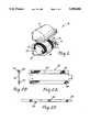
- FIG. 1is a exploded perspective view of a catalytic converter or diesel particulate trap of the present invention.
- FIG. 2Ais a plan view of the erosion resistant mounting composite of the invention.
- FIG. 2Bis an edge view of the erosion resistant mounting composite of the invention.
- FIG. 2Cis an end view of the erosion resistant mounting composite of the invention.
- catalytic converter or diesel particulate trap 10comprises metallic casing 11 with generally frustoconical inlet and outlet ends 12 and 13, respectively. Disposed within casing 11 is a monolithic catalytic element or diesel particulate filter 20 formed of a honeycombed ceramic having a plurality of gas flow channels 21 therethrough. Surrounding catalytic element or diesel particulate filter 20 is erosion resistant mounting composite 30 of the invention.
- Erosion resistant mounting composite 30is comprised of an intumescent mounting mat 32 protected on both lateral edges by a strip of metal fabric 34.
- Mounting composite 30serves to tightly but resiliently support catalytic element or diesel particulate filter 20 within the casing 11 by expansion in situ of mounting mat 32. It further acts to seal the gap between catalytic element or diesel particulate filter 20 and casing 11 to thus prevent exhaust gases from by-passing the catalytic element or diesel particulate filter 20.
- Metal fabric 34serves to protect the edges of mounting mat 32 from erosion caused by the impact of exhaust gases.
- the mounting mat 32is a resilient, flexible, intumescent sheet comprising from about 20% to 65% by weight of unexpanded vermiculite flakes, such flakes being either untreated or treated by being ion exchanged with an ammonium compound such as ammonium dihydrogen phosphate, ammonium carbonate, ammonium chloride or other suitable ammonium compound; from about 10% to 50% by weight of inorganic fibrous material including aluminosilicate fibers (available commercially under the tradenames Fiberfrax, Cerfiber, and Kaowool), asbestos fibers, soft glass fibers, zirconia-silica fibers and crystalline alumina whiskers; from about 3% to 20% by weight of binder including natural rubber latices, styrene-butadiene latices, butadiene acrylonitrile latices, latices of acrylate or methacrylate polymers and copolymers and the like; and up to about 40% by weight of inorganic filler including expanded ver
- the metal fabric 34 of this erosion resistant mounting composite 30 of this inventionis a strip of woven metal, preferably stainless steel, made of wire less than 1.0 mm in diameter, preferably about 0.23 mm diameter and having an open area of less than 85%, preferably about 40%.
- the fabric 34generally has square openings, although they can be rectangular, and are generally less than 7 mm wide, preferably about 0.4 mm wide.
- the intersecting wiresare generally of the same diameter, although not limited to being so.
- the clothIn order to maintain flexibility, the cloth must be oriented on the intumescent mat 32 such that the wires making up the cloth make an angle of from 15° to 75°, preferably 45° with the lengthwise edge of the mat.
- the wiresWhen woven, the wires cross at an angle of 90°, so the angle of one wire with respect to the edge of mounting composite 30 is the complement of the angle of the other wire (90° minus the angle of the other wire). Thus, either of the crossing, woven wires may be used to determine the angle of the mesh with respect to the edge of the mounting mat 32.
- metal fabricpreferably stainless steel
- knitted or braidedinstead of woven, made of wire less than 1.0 mm diameter, preferably about 0.15 mm diameter, with an open area of less than 85%.
- This fabricis generally softer and easier to handle than the woven cloth. Because of the curved nature of the wires making up the knitted or braided fabric, it can oriented in any direction on the mat edge without adversely affecting the flexibility of the mounting composite 30.
- the metal fabric 34 edge protectors described abovewere made from wires having a round cross section. They could, of course, be constructed of wires having square, rectangular or any other shaped cross section without departing from the scope of the present invention.
- the metal fabric 34 edge protectioncan be secured to the intumescent mounting mat 32 with tape or adhesive, or by mechanic means, such as sewing, stapling, staking or crimping. No external means of fastening is required if the fabric 34 is placed over the mounting mat 32 edge immediately prior to assembly of the converter or trap 10.
- the metal fabric 34 edge protectionshould extend 5 to 50 mm beyond the lengthwise edge of the intumescent mounting mat 32.
- the drawingsshow the metal fabric 34 edge protection to cover the entire length of the intumescent mounting mat 32. Naturally, it is possible to cover only a portion of one or both edges of the mounting mat 32.
- An erosion testwas devised to test the ability of mounting composites 30 to resist edge erosion from an impinging air stream.
- the testconsists of taking a 25.4 mm ⁇ 25.4 mm sample of mounting composite 30 and mounting it between two steel anvils to a predetermined gap by means of steel spacers. This assembly is then heated to 800° C. for one hour to burn out the organic binder. After weighing it to the nearest 0.01 g, it is mounted in a device where the edge of the mounting composite 30 is exposed to an impinging air stream of near sonic velocity, which oscillates along the edge of the mounting composite 30 at a rate of 20 cycles/second over a distance of 19 mm. The air stream oscillates at a distance of 3.8 mm from the edge of the sample.
- test resultsshow that the metal fabric 34 edge protection of the present invention drastically reduces the erosion rate of the intumescent mounting mat 32.
Landscapes
- Chemical & Material Sciences (AREA)
- Engineering & Computer Science (AREA)
- Chemical Kinetics & Catalysis (AREA)
- Mechanical Engineering (AREA)
- General Engineering & Computer Science (AREA)
- Combustion & Propulsion (AREA)
- Materials Engineering (AREA)
- Organic Chemistry (AREA)
- Toxicology (AREA)
- Inorganic Chemistry (AREA)
- Health & Medical Sciences (AREA)
- Exhaust Gas After Treatment (AREA)
- Connection Of Plates (AREA)
Abstract
Description
1. Field of the Invention
The present invention relates to a catalytic converter or diesel particulate trap used to clean the exhaust gas of an internal combustion engine and more particularly, to a catalytic converter or diesel particulate trap having a metallic casing with a monolithic catalytic element or diesel filter securely but resiliently mounted within the casing by an mounting composite comprised of a flexible, resilient, intumescent sheet which has its edges normal to the exhaust flow.
2. Description of the Prior Art
Catalytic converters are universally employed for oxidation of carbon monoxide and hydrocarbons and reduction of the oxides of nitrogen in automobile exhaust gas. Diesel particulate traps are used to collect soot generated by diesel engines. Collected soot is periodically burned off with a gas burner or electrical heater. Due to the high temperatures encountered in either of these environments, ceramic has been the logical choice for catalyst supports or diesel filters.
Ceramic monoliths tend to be frangible and have coefficients of thermal expansion differing markedly from their metal, usually stainless steel, containers. Thus, the mounting means of the ceramic monolith must provide resistance to mechanical shock due to impact and vibration and to thermal shock due to thermal cycling. Both thermal and mechanical shock may cause deterioration of the ceramic support which, once started, quickly accelerates and ultimately renders the device useless. Intumescent sheets that have been found adequate as mounting materials for this purpose are disclosed in U.S. Pat. Nos. 3,916,057, 4,305,992 and U.K. Patent No. 1,513,808.
Intumescent sheet mounting materials do an adequate job of holding the ceramic monolith or diesel particulate filter in place while resisting erosion at moderate exhaust temperatures (less than 700° C.), and moderate pressure pulsations of the exhaust gas, as in six and eight cylinder engines. However, with the trend towards smaller, four cylinder engines running at higher rotation velocities and with the advent of catalytic converters in Europe, with their high speed driving conditions, present mounting materials are being subjected to much higher exhaust temperatures and more severe pressure pulsations. Under these conditions, over a period of time, present mounting materials can be eroded.
It is therefore an object of this invention to provide a ceramic monolith mounting composite for catalytic converter elements or diesel particulate traps which can withstand the erosion effects of higher exhaust temperatures and more severe pressure pulsations associated with present operating conditions.
The present invention relates to a catalytic converter or diesel particulate trap for use in an exhaust system of an internal combustion engine wherein a novel erosion resistant mounting composite is utilized to securely mount the monolithic catalytic element or diesel particulate filter within its casing. The novel erosion resistant mounting composite is comprised of an intumescent mounting mat protected on at least a portion of one lateral edge by a strip of metal fabric wrapped around the lateral edge. The fabric is preferably stainless steel which is woven, knitted, or braided from wire less than 1.0 mm in diameter having an open area of less than 85%, preferably about 40%. Flexibility of the erosion resistant mounting composite when woven metal fabric is used is provided by orienting the wires comprising the woven metal fabric such that the wires, when wrapped about the lateral edge, form an angle of from 15° to 75°, preferably 45°, with the lengthwise direction of the edge.
FIG. 1 is a exploded perspective view of a catalytic converter or diesel particulate trap of the present invention; and
FIG. 2A is a plan view of the erosion resistant mounting composite of the invention.
FIG. 2B is an edge view of the erosion resistant mounting composite of the invention.
FIG. 2C is an end view of the erosion resistant mounting composite of the invention.
Referring now to the drawings, catalytic converter or dieselparticulate trap 10 comprises metallic casing 11 with generally frustoconical inlet andoutlet ends diesel particulate filter 20 formed of a honeycombed ceramic having a plurality ofgas flow channels 21 therethrough. Surrounding catalytic element ordiesel particulate filter 20 is erosionresistant mounting composite 30 of the invention.
Erosionresistant mounting composite 30 is comprised of anintumescent mounting mat 32 protected on both lateral edges by a strip ofmetal fabric 34. Mountingcomposite 30 serves to tightly but resiliently support catalytic element ordiesel particulate filter 20 within the casing 11 by expansion in situ of mountingmat 32. It further acts to seal the gap between catalytic element ordiesel particulate filter 20 and casing 11 to thus prevent exhaust gases from by-passing the catalytic element ordiesel particulate filter 20.Metal fabric 34 serves to protect the edges of mountingmat 32 from erosion caused by the impact of exhaust gases.
The mountingmat 32 is a resilient, flexible, intumescent sheet comprising from about 20% to 65% by weight of unexpanded vermiculite flakes, such flakes being either untreated or treated by being ion exchanged with an ammonium compound such as ammonium dihydrogen phosphate, ammonium carbonate, ammonium chloride or other suitable ammonium compound; from about 10% to 50% by weight of inorganic fibrous material including aluminosilicate fibers (available commercially under the tradenames Fiberfrax, Cerfiber, and Kaowool), asbestos fibers, soft glass fibers, zirconia-silica fibers and crystalline alumina whiskers; from about 3% to 20% by weight of binder including natural rubber latices, styrene-butadiene latices, butadiene acrylonitrile latices, latices of acrylate or methacrylate polymers and copolymers and the like; and up to about 40% by weight of inorganic filler including expanded vermiculite, hollow glass microspheres and bentonite. Themat 32 is made following basic papermaking techniques.
Themetal fabric 34 of this erosionresistant mounting composite 30 of this invention is a strip of woven metal, preferably stainless steel, made of wire less than 1.0 mm in diameter, preferably about 0.23 mm diameter and having an open area of less than 85%, preferably about 40%. Thefabric 34 generally has square openings, although they can be rectangular, and are generally less than 7 mm wide, preferably about 0.4 mm wide. The intersecting wires are generally of the same diameter, although not limited to being so. In order to maintain flexibility, the cloth must be oriented on theintumescent mat 32 such that the wires making up the cloth make an angle of from 15° to 75°, preferably 45° with the lengthwise edge of the mat. When woven, the wires cross at an angle of 90°, so the angle of one wire with respect to the edge ofmounting composite 30 is the complement of the angle of the other wire (90° minus the angle of the other wire). Thus, either of the crossing, woven wires may be used to determine the angle of the mesh with respect to the edge of themounting mat 32.
Also useful as an erosion protection for the mat is metal fabric, preferably stainless steel, that is knitted or braided instead of woven, made of wire less than 1.0 mm diameter, preferably about 0.15 mm diameter, with an open area of less than 85%. This fabric is generally softer and easier to handle than the woven cloth. Because of the curved nature of the wires making up the knitted or braided fabric, it can oriented in any direction on the mat edge without adversely affecting the flexibility of themounting composite 30.
Themetal fabric 34 edge protectors described above were made from wires having a round cross section. They could, of course, be constructed of wires having square, rectangular or any other shaped cross section without departing from the scope of the present invention.
Themetal fabric 34 edge protection can be secured to theintumescent mounting mat 32 with tape or adhesive, or by mechanic means, such as sewing, stapling, staking or crimping. No external means of fastening is required if thefabric 34 is placed over the mountingmat 32 edge immediately prior to assembly of the converter ortrap 10. Themetal fabric 34 edge protection should extend 5 to 50 mm beyond the lengthwise edge of theintumescent mounting mat 32. The drawings show themetal fabric 34 edge protection to cover the entire length of theintumescent mounting mat 32. Naturally, it is possible to cover only a portion of one or both edges of themounting mat 32.
An erosion test was devised to test the ability of mountingcomposites 30 to resist edge erosion from an impinging air stream. The test consists of taking a 25.4 mm×25.4 mm sample of mountingcomposite 30 and mounting it between two steel anvils to a predetermined gap by means of steel spacers. This assembly is then heated to 800° C. for one hour to burn out the organic binder. After weighing it to the nearest 0.01 g, it is mounted in a device where the edge of themounting composite 30 is exposed to an impinging air stream of near sonic velocity, which oscillates along the edge of themounting composite 30 at a rate of 20 cycles/second over a distance of 19 mm. The air stream oscillates at a distance of 3.8 mm from the edge of the sample. After testing, the sample is again weighed, and weight loss per unit time, i.e., erosion rate is calculated. Standard intumescent sheets sold under the brand name Interam.sup.™ Automotive Mat, Series IV of 4.9 mm nominal thickness were tested with and withoutvarious metal fabric 34 edge protections. Results are shown in Table I.
TABLE I______________________________________ MOUNT EROSION DENSITY RATEMATERIAL (g/cc) (g/cc)______________________________________Normal, No Protection 0.629 0.960Normal, No Protection 0.700 0.05520 mesh, 0.23 mm wire, 0.691 0.0023SS woven cloth protection40 mesh, 0.23 mm wire, 0.619 0.0004SS woven cloth protection100 density, 0.15 mm wire 0.759 0.0024SS knitted fabric protection______________________________________
The test results show that themetal fabric 34 edge protection of the present invention drastically reduces the erosion rate of the intumescent mountingmat 32.
To test the suitability ofvarious metal fabric 34 edge protections in terms of flexibility, various edge protections were bonded to the edges of intumescent mountingmat 32 parts and then wrapped around an 8.08 cm×16.97×12.7 cm long ovalcatalytic element 20. To be acceptable, the mountingcomposite 30 part must remain in contact with the surface of thecatalytic element 20 and not buckle when wrapped around it. Results are shown in Table II.
TABLE II______________________________________TYPE OF EDGEPROTECTION DESCRIPTION RESULTS______________________________________Stainless Steel Foil 0.05 mm thick, Unacceptable, annealed mat buckled20 mesh stainless 0.23 mm wire, wires Unacceptable,steel wovencloth 10° & 80° to length- mat buckledwise edge 20 mesh stainless 0.23 mm wire, wires Acceptable, nosteel wovencloth 20° & 70° to length- bucklingwise edge 20 mesh stainless 0.23 mm wire, wires Acceptable, nosteel woven cloth 45° to lengthwise edge buckling80 mesh stainless 0.14 mm wire, wire at Unacceptable,steel woven cloth 0° & 90° to lengthwise mat buckled edge80 mesh stainless 0.14 mm wire, wires at Acceptable, nosteel woven cloth 45° to lengthwise edge bucklingKnitted wire fabric 0.15 mm wire, 100 Acceptable, no density bucklingKnitted wire fabric 0.11 mm wire, 130 Acceptable, no density buckling______________________________________
Claims (18)
1. An improved catalytic converter including a metallic casing, a ceramic catalytic element disposed within the casing, and a mounting composite disposed between the catalytic element and the metallic casing for positioning the catalytic element within the casing and for absorbing mechanical and thermal shock, said mounting composite comprising a resilient, flexible, high temperature resistant intumescent mounting mat having a lateral edge, wherein the improvement comprises:
a strip of metal fabric positioned between at least a portion of the lateral edge of said mounting mat and said casing so to cover the lateral edge in order to prevent erosion of said mounting composite.
2. An improved catalytic converted according to claim 1 wherein the intumescent mounting mat comprises from 20% to 65% by weight of an unexpanded vermiculite, from 10% to 50% by weight of an inorganic fibrous material and from 3% to 20% by weight of a binder.
3. An improved catalytic converter according to claim 2 wherein said vermiculite has been ion-exchanged with an ammonium compound.
4. An improved catalytic converter according to claim 2 wherein said inorganic fibrous material is asbestos, soft glass fiber, alumina whisker, alumina-silica fiber or zirconia-silica fiber.
5. An improved catalytic converter according to claim 2 wherein said binder is an organic or inorganic material or combination thereof.
6. An improved catalytic converter according to claim 1 wherein said metal fabric is selected from the group consisting of steel, stainless steel, galvanized steel, metal alloys or combinations thereof.
7. An improved catalytic converter according to claim 6 wherein said metal fabric comprises a multiplicity of wires formed as a woven, braided or knitted wire fabric.
8. An improved catalytic converter according to claim 7 wherein said metal wires are less than 1.0 mm in diameter.
9. An improved catalytic converter according to claim 7 wherein said woven wire fabric is wrapped about said intumescent mounting mat edge and said wires of said metal fabric form an angle of from 15° to 75° with said edge.
10. An improved diesel particle trap including a metallic casing, a ceramic diesel particulate filter disposed within the casing, and a mounting composite disposed between the diesel particulate filter and the metallic casing for positioning the particulate filter and for absorbing mechanical and thermal shock, said mounting composite comprising a resilient, flexible, high temperature resistant intumescent mounting mat having a lateral edge, wherein the improvement comprises:
a strip of metal fabric positioned between at least a portion of the lateral edge of said mounting mat and said casing, so as to cover the lateral edge, in order to prevent erosion of said mounting composite.
11. An improved diesel particulate trap according to claim 10 wherein the intumescent mounting mat comprises from 20% to 65% by weight of an unexpanded vermiculite, from 10% to 50% by weight of an inorganic fibrous material and from 3% to 20% by weight of a binder.
12. An improved diesel particulate trap according to claim 11 wherein said unexpanded vermiculite has been ion-exchanged with an ammonium compound.
13. An improved diesel particulate trap according to clam 11 wherein said inorganic fibrous material is selected from a group consisting of asbestos, soft glass fiber, alumina whisker, alumina-silica fiber or zirconia-silica fiber.
14. An improved diesel particulate trap according to claim 11 wherein said binder is an organic or inorganic material or combination thereof.
15. An improved diesel particulate trap according to claim 10 wherein said metal fabric is selected from the group consisting of steel, stainless steel, galvanized steel, metal alloys or combinations thereof.
16. An improved diesel particulate trap according to claim 15 wherein said metal fabric comprises a multiplicity of wires formed as a woven, braided or knitted wire fabric.
17. An improved diesel particulate trap according to claim 16 wherein said metal wires are less than 1.0 mm in diameter.
18. An improved diesel particulate trap according to claim 16 wherein the wires of said woven wire fabric when wrapped about the intumescent mounting mat edge form an angle of from 15° to 75° with the lateral edge.
Priority Applications (9)
| Application Number | Priority Date | Filing Date | Title |
|---|---|---|---|
| US07/263,683US5008086A (en) | 1988-10-28 | 1988-10-28 | Erosion resistant mounting composite for catalytic converter |
| CA000613014ACA1326455C (en) | 1988-10-28 | 1989-09-25 | Erosion resistant mounting composite for catalytic converter |
| AU42386/89AAU614428B2 (en) | 1988-10-28 | 1989-09-28 | Erosion resistant mounting composite for catalytic converter |
| MX017831AMX166480B (en) | 1988-10-28 | 1989-10-04 | IMPROVED CATALYTIC CONVERTER |
| JP1989122681UJP2577783Y2 (en) | 1988-10-28 | 1989-10-19 | Improved catalytic converter |
| EP89311102AEP0366484B2 (en) | 1988-10-28 | 1989-10-27 | Erosion resistant mounting composite for catalytic converter |
| ES89311102TES2050814T5 (en) | 1988-10-28 | 1989-10-27 | EROSION RESISTANT COMPOSITE MOUNTING MATERIAL FOR CATALYTIC CONVERTER. |
| KR2019890015628UKR950002843Y1 (en) | 1988-10-28 | 1989-10-27 | Corrosion-resistant Loading Composites for Catalytic Converters |
| DE68913270TDE68913270T3 (en) | 1988-10-28 | 1989-10-27 | Erosion-resistant component for a catalytic converter. |
Applications Claiming Priority (1)
| Application Number | Priority Date | Filing Date | Title |
|---|---|---|---|
| US07/263,683US5008086A (en) | 1988-10-28 | 1988-10-28 | Erosion resistant mounting composite for catalytic converter |
Publications (1)
| Publication Number | Publication Date |
|---|---|
| US5008086Atrue US5008086A (en) | 1991-04-16 |
Family
ID=23002820
Family Applications (1)
| Application Number | Title | Priority Date | Filing Date |
|---|---|---|---|
| US07/263,683Expired - LifetimeUS5008086A (en) | 1988-10-28 | 1988-10-28 | Erosion resistant mounting composite for catalytic converter |
Country Status (9)
| Country | Link |
|---|---|
| US (1) | US5008086A (en) |
| EP (1) | EP0366484B2 (en) |
| JP (1) | JP2577783Y2 (en) |
| KR (1) | KR950002843Y1 (en) |
| AU (1) | AU614428B2 (en) |
| CA (1) | CA1326455C (en) |
| DE (1) | DE68913270T3 (en) |
| ES (1) | ES2050814T5 (en) |
| MX (1) | MX166480B (en) |
Cited By (93)
| Publication number | Priority date | Publication date | Assignee | Title |
|---|---|---|---|---|
| WO1992016282A1 (en)* | 1991-03-22 | 1992-10-01 | Acs Industries, Inc. | Seal for catalytic converter and method therefor |
| US5298046A (en)* | 1993-01-06 | 1994-03-29 | Minnesota Mining And Manufacturing Company | Diesel particulate filter element and filter |
| EP0639700A1 (en)* | 1993-08-20 | 1995-02-22 | Minnesota Mining And Manufacturing Company | Catalytic converter and diesel particulate filter |
| EP0639702A1 (en)* | 1993-08-20 | 1995-02-22 | Minnesota Mining And Manufacturing Company | Mounting mat edge protection and mounting mat with high temperature sealing material |
| US5409670A (en)* | 1993-08-13 | 1995-04-25 | Peerless Manufacturing Company | SCR reactor sealing mechanism |
| US5413766A (en)* | 1991-10-04 | 1995-05-09 | Leistritz Ag & Co. Abgastechnik | Device for reducing exhaust gas contaminants, particularly for motor vehicles |
| US5449500A (en)* | 1994-07-14 | 1995-09-12 | Acs Industries, Inc. | Barrier strip for a support mat in a catalytic converter |
| US5523059A (en)* | 1995-06-30 | 1996-06-04 | Minnesota Mining And Manufacturing Company | Intumescent sheet material with glass fibers |
| WO1997002414A1 (en)* | 1995-06-30 | 1997-01-23 | Minnesota Mining And Manufacturing Company | Methods of making a catalytic converter or diesel particulate filter |
| GB2314034A (en)* | 1996-06-15 | 1997-12-17 | Catalytic Support Syst Ltd | Support and seal for a catalytic converter |
| US5736109A (en)* | 1995-06-30 | 1998-04-07 | Minnesota Mining And Manufacturing Company | Intumescent sheet material and paste with organic binder |
| WO1998035144A1 (en) | 1997-02-06 | 1998-08-13 | Minnesota Mining And Manufacturing Company | Multilayer intumescent sheet |
| US5853675A (en)* | 1995-06-30 | 1998-12-29 | Minnesota Mining And Manufacturing Company | Composite mounting system |
| US5866079A (en)* | 1993-09-03 | 1999-02-02 | Ngk Insulators, Ltd. | Ceramic honeycomb catalytic converter |
| US5869010A (en)* | 1995-06-30 | 1999-02-09 | Minnesota Mining And Manufacturing Company | Intumescent sheet material |
| US5882608A (en)* | 1996-06-18 | 1999-03-16 | Minnesota Mining And Manufacturing Company | Hybrid mounting system for pollution control devices |
| US5953817A (en)* | 1995-10-12 | 1999-09-21 | Toyota Jidosha Kabushiki Kaisha | Process for producing monolithic catalyst converter |
| DE19819083A1 (en)* | 1998-04-29 | 1999-11-04 | Bayerische Motoren Werke Ag | Exhaust gas catalyst with ceramic monolith |
| WO2001000304A1 (en)* | 1999-06-28 | 2001-01-04 | Arvinmeritor, Inc. | Substrate retainer for exhaust processor |
| US6325834B1 (en)* | 1998-05-18 | 2001-12-04 | Roberto Fonseca | Exhaust filter and catalyst structure |
| JP2002147231A (en)* | 2000-11-10 | 2002-05-22 | Ibiden Co Ltd | Catalytic converter and holding sealant for the same |
| US20020071791A1 (en)* | 2000-12-13 | 2002-06-13 | Foster Michael Ralph | Catalytic converter |
| US20020076362A1 (en)* | 2000-12-15 | 2002-06-20 | Hardesty Jeffrey B. | Exhaust manifold with catalytic converter shell tube |
| US20020150518A1 (en)* | 2001-04-13 | 2002-10-17 | Brush Dagan W. | Gas treatment device |
| EP1031709A3 (en)* | 1999-02-25 | 2003-02-05 | LEISTRITZ AG & CO. Abgastechnik | Exhaust gas catalyst |
| US6537355B2 (en)* | 2000-12-27 | 2003-03-25 | Delphi Technologies, Inc. | Evaporative emission treatment device |
| US20030091479A1 (en)* | 2001-11-09 | 2003-05-15 | Zlatomir Kircanski | High temperature resistant material |
| EP1314866A2 (en) | 1997-02-06 | 2003-05-28 | Minnesota Mining And Manufacturing Company | Multilayer intumescent sheet |
| US20030097752A1 (en)* | 1997-05-09 | 2003-05-29 | 3M Innovative Properties Company | Compressible preform insulating liner |
| US20030129101A1 (en)* | 2002-01-10 | 2003-07-10 | Steven Zettel | Catalytic monolith support system with improved thermal resistance and mechanical properties |
| US20030190269A1 (en)* | 2000-03-09 | 2003-10-09 | Liu Z. Gerald | Catalyst and filter combination |
| US6670020B1 (en)* | 1998-01-13 | 2003-12-30 | Emitec Gesellschaft Fuer Emissionstechnologie Mbh | Honeycomb body configuration with an intermediate layer containing at least one metal layer and sandwich structure in particular for a honeycomb body configuration |
| US6669913B1 (en) | 2000-03-09 | 2003-12-30 | Fleetguard, Inc. | Combination catalytic converter and filter |
| US20040022699A1 (en)* | 2000-11-10 | 2004-02-05 | Koji Fukushima | Catalytic converter and method for manufacture thereof |
| US20040052697A1 (en)* | 2002-09-18 | 2004-03-18 | Mcintosh Loel E. | Catalytic converter |
| US20040062690A1 (en)* | 2002-09-30 | 2004-04-01 | Nichias Corporation | Holding material for catalytic converter |
| US6726884B1 (en)* | 1996-06-18 | 2004-04-27 | 3M Innovative Properties Company | Free-standing internally insulating liner |
| US20040098963A1 (en)* | 2001-02-15 | 2004-05-27 | Jan Calleeuw | Metal rope and fabric comprising such a metal rope |
| EP1342888A4 (en)* | 2000-11-10 | 2004-06-16 | Ibiden Co Ltd | Catalytic converter and method for manufacture thereof |
| US6759015B2 (en) | 1999-03-23 | 2004-07-06 | 3M Innovative Properties Company | Insulated mounting for a pollution control device |
| US6776814B2 (en) | 2000-03-09 | 2004-08-17 | Fleetguard, Inc. | Dual section exhaust aftertreatment filter and method |
| US20040194440A1 (en)* | 2001-10-29 | 2004-10-07 | Emitec Gesellschaft Fur Emissionstechnologie Mbh | Heat-resistant filter layer, filter body, and process for producing the filter layer and the filter body |
| US20050002836A1 (en)* | 2001-04-13 | 2005-01-06 | Hardesty Jeffrey B. | Gas treatment device, and methods of making and using the same |
| US6946013B2 (en) | 2002-10-28 | 2005-09-20 | Geo2 Technologies, Inc. | Ceramic exhaust filter |
| US20050232828A1 (en)* | 2004-04-14 | 2005-10-20 | 3M Innovative Properties Company | Sandwich hybrid mounting mat |
| US20050232827A1 (en)* | 2004-04-14 | 2005-10-20 | 3M Innovative Properties Company | Multilayer mats for use in pollution control devices |
| US6967006B1 (en)* | 1998-01-28 | 2005-11-22 | J. Eberspächer GmbH & Co. KG | Method for mounting and insulating ceramic monoliths in an automobile exhaust system and a mounting produced according to this method |
| US20060070554A1 (en)* | 2003-01-22 | 2006-04-06 | Braunreiter Carl J | Molded three-dimensional insulator |
| US7052532B1 (en) | 2000-03-09 | 2006-05-30 | 3M Innovative Properties Company | High temperature nanofilter, system and method |
| US7211232B1 (en) | 2005-11-07 | 2007-05-01 | Geo2 Technologies, Inc. | Refractory exhaust filtering method and apparatus |
| US20070207070A1 (en)* | 2006-03-03 | 2007-09-06 | Bilal Zuberi | Catalytic exhaust filter device |
| US20080178413A1 (en)* | 2007-01-30 | 2008-07-31 | Wagner Wayne M | Apparatus for Cleaning Exhaust Aftertreatment Devices and Methods |
| WO2008103525A2 (en) | 2007-02-19 | 2008-08-28 | 3M Innovative Properties Company | Flexible fibrous material, pollution control device, and methods of making the same |
| US7444805B2 (en) | 2005-12-30 | 2008-11-04 | Geo2 Technologies, Inc. | Substantially fibrous refractory device for cleaning a fluid |
| US7451849B1 (en) | 2005-11-07 | 2008-11-18 | Geo2 Technologies, Inc. | Substantially fibrous exhaust screening system for motor vehicles |
| US20080295690A1 (en)* | 2007-05-31 | 2008-12-04 | International Truck Intellectual Property Company, Llc | Diesel particulate filter pulse cleaner flow director system and method |
| US20090084268A1 (en)* | 2007-09-28 | 2009-04-02 | Ibiden Co., Ltd. | Mat member, method of fabricating mat member, exhaust gas treating apparatus, and silencing device |
| US20090087353A1 (en)* | 2007-09-28 | 2009-04-02 | Ibiden Co., Ltd. | Mat member, exhaust gas treatment apparatus, and muffling apparatus |
| US7572311B2 (en) | 2002-10-28 | 2009-08-11 | Geo2 Technologies, Inc. | Highly porous mullite particulate filter substrate |
| US7574796B2 (en) | 2002-10-28 | 2009-08-18 | Geo2 Technologies, Inc. | Nonwoven composites and related products and methods |
| US7582270B2 (en) | 2002-10-28 | 2009-09-01 | Geo2 Technologies, Inc. | Multi-functional substantially fibrous mullite filtration substrates and devices |
| US20100037423A1 (en)* | 2008-07-10 | 2010-02-18 | Herman John T | Apparatus for Cleaning Exhaust Aftertreatment Devices and Methods |
| US20100055004A1 (en)* | 2008-08-29 | 2010-03-04 | Unifrax I Llc | Mounting mat with flexible edge protection and exhaust gas treatment device incorporating the mounting mat |
| US7682578B2 (en) | 2005-11-07 | 2010-03-23 | Geo2 Technologies, Inc. | Device for catalytically reducing exhaust |
| US7682577B2 (en) | 2005-11-07 | 2010-03-23 | Geo2 Technologies, Inc. | Catalytic exhaust device for simplified installation or replacement |
| US7722828B2 (en) | 2005-12-30 | 2010-05-25 | Geo2 Technologies, Inc. | Catalytic fibrous exhaust system and method for catalyzing an exhaust gas |
| US20100173552A1 (en)* | 2009-01-05 | 2010-07-08 | Unifrax I Llc | High strength biosoluble inorganic fiber insulation mat |
| WO2010105000A1 (en) | 2009-03-13 | 2010-09-16 | 3M Innovative Properties Company | Mat and devices with the same |
| US20100266462A1 (en)* | 2009-04-17 | 2010-10-21 | Amit Kumar | Exhaust Gas Treatment Device |
| US20110023430A1 (en)* | 2007-08-31 | 2011-02-03 | Amit Kumar | Multiple Layer Substrate Support and Exhaust Gas Treatment Device |
| US20110033343A1 (en)* | 2009-08-10 | 2011-02-10 | Fernandes Jr Sergio David | Variable basis weight mounting mat or pre-form and exhaust gas treatment device |
| US20110030356A1 (en)* | 2007-07-10 | 2011-02-10 | Daigo Yasuda | Pollution control devices, reinforced mat material for use therein and methods of making same |
| WO2011047001A1 (en) | 2009-10-13 | 2011-04-21 | 3M Innovative Properties Company | Non-woven mat and pollution control device with the same |
| US20110094419A1 (en)* | 2008-12-15 | 2011-04-28 | Fernando Joseph A | Ceramic Honeycomb Structure Skin Coating |
| US20110123417A1 (en)* | 2004-06-29 | 2011-05-26 | Ten Eyck John D | Exhaust gas treatment device |
| US20110126499A1 (en)* | 2009-09-24 | 2011-06-02 | Amit Kumar | Multiple Layer Mat and Exhaust Gas Treatment Device |
| US20110150715A1 (en)* | 2009-12-17 | 2011-06-23 | Unifrax I Llc | Multilayer Mounting Mat for Pollution Control Devices |
| US20110150717A1 (en)* | 2009-12-17 | 2011-06-23 | Unifrax I Llc | Mounting mat for exhaust gas treatment device |
| US20110182777A1 (en)* | 2007-06-13 | 2011-07-28 | 3M Innovative Properties Company | Erosion resistant mounting material and method of making and using the same |
| US20110289895A1 (en)* | 2004-07-10 | 2011-12-01 | Mann+Hummel Gmbh | Ceramic Filter Element with Structural Elements and Production Method |
| US8071040B2 (en) | 2009-09-23 | 2011-12-06 | Unifax I LLC | Low shear mounting mat for pollution control devices |
| US8349265B2 (en) | 2010-08-13 | 2013-01-08 | Unifrax I Llc | Mounting mat with flexible edge protection and exhaust gas treatment device incorporating the mounting mat |
| US8404187B1 (en) | 1998-03-11 | 2013-03-26 | Unifrax I Llc | Support element for fragile structures such as catalytic converters |
| US8702832B2 (en) | 2007-06-13 | 2014-04-22 | 3M Innovative Properties Company | Securable mounting material and method of making and using the same |
| US8721977B2 (en) | 2011-10-07 | 2014-05-13 | Tenneco Automotive Operating Company Inc. | Exhaust treatment device with integral mount |
| US8765069B2 (en) | 2010-08-12 | 2014-07-01 | Unifrax I Llc | Exhaust gas treatment device |
| US8820691B2 (en) | 2012-06-28 | 2014-09-02 | Electro-Motive Diesel, Inc. | Adjustable support structure for an after-treatment component |
| US8926911B2 (en) | 2009-12-17 | 2015-01-06 | Unifax I LLC | Use of microspheres in an exhaust gas treatment device mounting mat |
| WO2015094957A1 (en) | 2013-12-19 | 2015-06-25 | 3M Innovative Properties Company | Using recycled waste water to make nonwoven fibrous materials suitable for use in a pollution control device or in a firestop |
| US9120703B2 (en) | 2010-11-11 | 2015-09-01 | Unifrax I Llc | Mounting mat and exhaust gas treatment device |
| US9140174B2 (en) | 2011-10-07 | 2015-09-22 | Tenneco Automotive Operating Company Inc. | Exhaust treatment device with integral mount |
| US9174169B2 (en) | 2009-08-14 | 2015-11-03 | Unifrax I Llc | Mounting mat for exhaust gas treatment device |
| US9452719B2 (en) | 2015-02-24 | 2016-09-27 | Unifrax I Llc | High temperature resistant insulation mat |
Families Citing this family (6)
| Publication number | Priority date | Publication date | Assignee | Title |
|---|---|---|---|---|
| GB2268095A (en)* | 1992-06-24 | 1994-01-05 | Catalytic Support Syst Ltd | Improvements in or relating to catalytic converters and diesel particulate traps |
| GB2273100B (en)* | 1992-11-18 | 1997-01-08 | Environmental Seals Ltd | Intumescent products |
| GB9716493D0 (en) | 1997-08-05 | 1997-10-08 | Forber Stephen M | Composite metal mesh and ceramic fibre exhaust gas sealing and support mounting device for use with catalytic converting systems |
| RU2136911C1 (en)* | 1997-11-12 | 1999-09-10 | Акционерное общество "АвтоВАЗ" | Exhaust gas catalyst converter and method of its manufacture |
| DE69922848T2 (en)* | 1999-06-08 | 2005-12-08 | 3M Innovative Properties Co., St. Paul | HIGH-TEMPERATURE-RESISTANT LAGMAT FOR AN EXHAUST GAS CLEANING DEVICE |
| US20050097893A1 (en)* | 2003-11-07 | 2005-05-12 | General Electric Company | Method and apparatus for increasing a durability of a body |
Citations (5)
| Publication number | Priority date | Publication date | Assignee | Title |
|---|---|---|---|---|
| US3916057A (en)* | 1973-08-31 | 1975-10-28 | Minnesota Mining & Mfg | Intumescent sheet material |
| GB1513808A (en)* | 1974-11-04 | 1978-06-07 | Minnesota Mining & Mfg | Intumescant sheet material |
| US4305992A (en)* | 1979-11-28 | 1981-12-15 | Minnesota Mining And Manufacturing Company | Intumescent sheet material |
| US4619912A (en)* | 1985-09-03 | 1986-10-28 | General Motors Corporation | Catalytic converter substrate |
| US4818497A (en)* | 1986-06-16 | 1989-04-04 | Sandvik Ab | Device for purification of exhaust gases |
Family Cites Families (5)
| Publication number | Priority date | Publication date | Assignee | Title |
|---|---|---|---|---|
| JPS58221071A (en)* | 1982-06-15 | 1983-12-22 | Toyota Motor Corp | Elastic retaining/sealing member and manufacturing method thereof |
| JPS60170021U (en)* | 1984-04-19 | 1985-11-11 | カルソニックカンセイ株式会社 | catalytic converter |
| JPS61169220U (en)* | 1985-04-11 | 1986-10-20 | ||
| JPS61181816U (en)* | 1985-05-01 | 1986-11-13 | ||
| CA1310275C (en)* | 1987-12-04 | 1992-11-17 | Richard P. Merry | Catalytic converter particulate filter for exhaust systems |
- 1988
- 1988-10-28USUS07/263,683patent/US5008086A/ennot_activeExpired - Lifetime
- 1989
- 1989-09-25CACA000613014Apatent/CA1326455C/ennot_activeExpired - Fee Related
- 1989-09-28AUAU42386/89Apatent/AU614428B2/ennot_activeCeased
- 1989-10-04MXMX017831Apatent/MX166480B/enunknown
- 1989-10-19JPJP1989122681Upatent/JP2577783Y2/ennot_activeExpired - Lifetime
- 1989-10-27KRKR2019890015628Upatent/KR950002843Y1/ennot_activeExpired - Fee Related
- 1989-10-27EPEP89311102Apatent/EP0366484B2/ennot_activeExpired - Lifetime
- 1989-10-27DEDE68913270Tpatent/DE68913270T3/ennot_activeExpired - Fee Related
- 1989-10-27ESES89311102Tpatent/ES2050814T5/ennot_activeExpired - Lifetime
Patent Citations (5)
| Publication number | Priority date | Publication date | Assignee | Title |
|---|---|---|---|---|
| US3916057A (en)* | 1973-08-31 | 1975-10-28 | Minnesota Mining & Mfg | Intumescent sheet material |
| GB1513808A (en)* | 1974-11-04 | 1978-06-07 | Minnesota Mining & Mfg | Intumescant sheet material |
| US4305992A (en)* | 1979-11-28 | 1981-12-15 | Minnesota Mining And Manufacturing Company | Intumescent sheet material |
| US4619912A (en)* | 1985-09-03 | 1986-10-28 | General Motors Corporation | Catalytic converter substrate |
| US4818497A (en)* | 1986-06-16 | 1989-04-04 | Sandvik Ab | Device for purification of exhaust gases |
Cited By (146)
| Publication number | Priority date | Publication date | Assignee | Title |
|---|---|---|---|---|
| WO1992016282A1 (en)* | 1991-03-22 | 1992-10-01 | Acs Industries, Inc. | Seal for catalytic converter and method therefor |
| US5207989A (en)* | 1991-03-22 | 1993-05-04 | Acs Industries, Inc. | Seal for catalytic converter and method therefor |
| US5385873A (en)* | 1991-03-22 | 1995-01-31 | Acs Industries, Inc. | High temperature resistant material |
| US5413766A (en)* | 1991-10-04 | 1995-05-09 | Leistritz Ag & Co. Abgastechnik | Device for reducing exhaust gas contaminants, particularly for motor vehicles |
| US5298046A (en)* | 1993-01-06 | 1994-03-29 | Minnesota Mining And Manufacturing Company | Diesel particulate filter element and filter |
| US5409670A (en)* | 1993-08-13 | 1995-04-25 | Peerless Manufacturing Company | SCR reactor sealing mechanism |
| EP0639700A1 (en)* | 1993-08-20 | 1995-02-22 | Minnesota Mining And Manufacturing Company | Catalytic converter and diesel particulate filter |
| EP0639702A1 (en)* | 1993-08-20 | 1995-02-22 | Minnesota Mining And Manufacturing Company | Mounting mat edge protection and mounting mat with high temperature sealing material |
| US6245301B1 (en) | 1993-08-20 | 2001-06-12 | 3M Innovative Properties Company | Catalytic converter and diesel particulate filter |
| US5866079A (en)* | 1993-09-03 | 1999-02-02 | Ngk Insulators, Ltd. | Ceramic honeycomb catalytic converter |
| US5449500A (en)* | 1994-07-14 | 1995-09-12 | Acs Industries, Inc. | Barrier strip for a support mat in a catalytic converter |
| WO1997002218A1 (en)* | 1995-06-30 | 1997-01-23 | Minnesota Mining And Manufacturing Company | Intumescent sheet material with glass fibers |
| US5686039A (en)* | 1995-06-30 | 1997-11-11 | Minnesota Mining And Manufacturing Company | Methods of making a catalytic converter or diesel particulate filter |
| WO1997002414A1 (en)* | 1995-06-30 | 1997-01-23 | Minnesota Mining And Manufacturing Company | Methods of making a catalytic converter or diesel particulate filter |
| US5736109A (en)* | 1995-06-30 | 1998-04-07 | Minnesota Mining And Manufacturing Company | Intumescent sheet material and paste with organic binder |
| US5523059A (en)* | 1995-06-30 | 1996-06-04 | Minnesota Mining And Manufacturing Company | Intumescent sheet material with glass fibers |
| US5853675A (en)* | 1995-06-30 | 1998-12-29 | Minnesota Mining And Manufacturing Company | Composite mounting system |
| US5869010A (en)* | 1995-06-30 | 1999-02-09 | Minnesota Mining And Manufacturing Company | Intumescent sheet material |
| US5953817A (en)* | 1995-10-12 | 1999-09-21 | Toyota Jidosha Kabushiki Kaisha | Process for producing monolithic catalyst converter |
| GB2314034B (en)* | 1996-06-15 | 2000-04-12 | Catalytic Support Syst Ltd | A seal assembly |
| GB2314034A (en)* | 1996-06-15 | 1997-12-17 | Catalytic Support Syst Ltd | Support and seal for a catalytic converter |
| US5882608A (en)* | 1996-06-18 | 1999-03-16 | Minnesota Mining And Manufacturing Company | Hybrid mounting system for pollution control devices |
| US6726884B1 (en)* | 1996-06-18 | 2004-04-27 | 3M Innovative Properties Company | Free-standing internally insulating liner |
| US20040052698A1 (en)* | 1996-06-18 | 2004-03-18 | 3M Innovative Properties Company | Hybrid mounting system for pollution control devices |
| US20040137175A1 (en)* | 1996-06-18 | 2004-07-15 | 3M Innovative Properties Company | Free-standing internally insulating liner |
| US6613294B2 (en) | 1996-06-18 | 2003-09-02 | 3M Innovative Properties Company | Hybrid mounting system for pollution control devices |
| US7501099B2 (en)* | 1996-06-18 | 2009-03-10 | 3M Innovative Properties Company | Hybrid mounting system for pollution control devices |
| WO1998035144A1 (en) | 1997-02-06 | 1998-08-13 | Minnesota Mining And Manufacturing Company | Multilayer intumescent sheet |
| EP1314866A2 (en) | 1997-02-06 | 2003-05-28 | Minnesota Mining And Manufacturing Company | Multilayer intumescent sheet |
| US8182751B2 (en) | 1997-05-09 | 2012-05-22 | 3M Innovative Properties Company | Self-supporting insulating end cone liner and pollution control device |
| US8632727B2 (en) | 1997-05-09 | 2014-01-21 | 3M Innovative Properties Company | Self-supporting insulating end cone liner and pollution control device |
| US7758795B2 (en) | 1997-05-09 | 2010-07-20 | 3M Innovative Properties Company | Method of making a polluction control device and a self-supporting insulating end cone |
| US20030097752A1 (en)* | 1997-05-09 | 2003-05-29 | 3M Innovative Properties Company | Compressible preform insulating liner |
| US8741200B2 (en) | 1997-05-09 | 2014-06-03 | 3M Innovative Properties Company | Method of making self-supporting insulating end cone liners and pollution control devices |
| US6670020B1 (en)* | 1998-01-13 | 2003-12-30 | Emitec Gesellschaft Fuer Emissionstechnologie Mbh | Honeycomb body configuration with an intermediate layer containing at least one metal layer and sandwich structure in particular for a honeycomb body configuration |
| US6967006B1 (en)* | 1998-01-28 | 2005-11-22 | J. Eberspächer GmbH & Co. KG | Method for mounting and insulating ceramic monoliths in an automobile exhaust system and a mounting produced according to this method |
| US8404187B1 (en) | 1998-03-11 | 2013-03-26 | Unifrax I Llc | Support element for fragile structures such as catalytic converters |
| DE19819083A1 (en)* | 1998-04-29 | 1999-11-04 | Bayerische Motoren Werke Ag | Exhaust gas catalyst with ceramic monolith |
| US6325834B1 (en)* | 1998-05-18 | 2001-12-04 | Roberto Fonseca | Exhaust filter and catalyst structure |
| EP1031709A3 (en)* | 1999-02-25 | 2003-02-05 | LEISTRITZ AG & CO. Abgastechnik | Exhaust gas catalyst |
| US6759015B2 (en) | 1999-03-23 | 2004-07-06 | 3M Innovative Properties Company | Insulated mounting for a pollution control device |
| WO2001000304A1 (en)* | 1999-06-28 | 2001-01-04 | Arvinmeritor, Inc. | Substrate retainer for exhaust processor |
| US20030190269A1 (en)* | 2000-03-09 | 2003-10-09 | Liu Z. Gerald | Catalyst and filter combination |
| US6776814B2 (en) | 2000-03-09 | 2004-08-17 | Fleetguard, Inc. | Dual section exhaust aftertreatment filter and method |
| US7235124B2 (en) | 2000-03-09 | 2007-06-26 | 3M Innovative Properties Company | High temperature nanofilter, system and method |
| US7211226B2 (en) | 2000-03-09 | 2007-05-01 | Fleetgaurd, Inc. | Catalyst and filter combination |
| US20060254426A1 (en)* | 2000-03-09 | 2006-11-16 | 3M Innovative Properties Company And Fleetguard, Inc. | High temperature nanofilter, system and method |
| US7052532B1 (en) | 2000-03-09 | 2006-05-30 | 3M Innovative Properties Company | High temperature nanofilter, system and method |
| US6669913B1 (en) | 2000-03-09 | 2003-12-30 | Fleetguard, Inc. | Combination catalytic converter and filter |
| US7575727B2 (en)* | 2000-11-10 | 2009-08-18 | Ibiden Co., Ltd. | Catalytic converter and method for manufacturing the same |
| JP2002147231A (en)* | 2000-11-10 | 2002-05-22 | Ibiden Co Ltd | Catalytic converter and holding sealant for the same |
| EP1342888A4 (en)* | 2000-11-10 | 2004-06-16 | Ibiden Co Ltd | Catalytic converter and method for manufacture thereof |
| US20040022699A1 (en)* | 2000-11-10 | 2004-02-05 | Koji Fukushima | Catalytic converter and method for manufacture thereof |
| US20020071791A1 (en)* | 2000-12-13 | 2002-06-13 | Foster Michael Ralph | Catalytic converter |
| US7241426B2 (en) | 2000-12-15 | 2007-07-10 | Delphi Technologies, Inc. | Exhaust manifold with catalytic converter shell tube |
| US20020076362A1 (en)* | 2000-12-15 | 2002-06-20 | Hardesty Jeffrey B. | Exhaust manifold with catalytic converter shell tube |
| US6537355B2 (en)* | 2000-12-27 | 2003-03-25 | Delphi Technologies, Inc. | Evaporative emission treatment device |
| US20040098963A1 (en)* | 2001-02-15 | 2004-05-27 | Jan Calleeuw | Metal rope and fabric comprising such a metal rope |
| US20050002836A1 (en)* | 2001-04-13 | 2005-01-06 | Hardesty Jeffrey B. | Gas treatment device, and methods of making and using the same |
| US20020150518A1 (en)* | 2001-04-13 | 2002-10-17 | Brush Dagan W. | Gas treatment device |
| US20040194440A1 (en)* | 2001-10-29 | 2004-10-07 | Emitec Gesellschaft Fur Emissionstechnologie Mbh | Heat-resistant filter layer, filter body, and process for producing the filter layer and the filter body |
| US7261755B2 (en)* | 2001-10-29 | 2007-08-28 | Emitec Gesellschaft Fuer Emissionstechnologie Mbh | Heat-resistant filter layer, filter body, and process for producing the filter layer and the filter body |
| US20030091479A1 (en)* | 2001-11-09 | 2003-05-15 | Zlatomir Kircanski | High temperature resistant material |
| US20030129101A1 (en)* | 2002-01-10 | 2003-07-10 | Steven Zettel | Catalytic monolith support system with improved thermal resistance and mechanical properties |
| US20040052697A1 (en)* | 2002-09-18 | 2004-03-18 | Mcintosh Loel E. | Catalytic converter |
| US20040062690A1 (en)* | 2002-09-30 | 2004-04-01 | Nichias Corporation | Holding material for catalytic converter |
| US7306773B2 (en)* | 2002-09-30 | 2007-12-11 | Nichias Corporation | Holding material for catalytic converter |
| US6946013B2 (en) | 2002-10-28 | 2005-09-20 | Geo2 Technologies, Inc. | Ceramic exhaust filter |
| US7582270B2 (en) | 2002-10-28 | 2009-09-01 | Geo2 Technologies, Inc. | Multi-functional substantially fibrous mullite filtration substrates and devices |
| US7572311B2 (en) | 2002-10-28 | 2009-08-11 | Geo2 Technologies, Inc. | Highly porous mullite particulate filter substrate |
| US7574796B2 (en) | 2002-10-28 | 2009-08-18 | Geo2 Technologies, Inc. | Nonwoven composites and related products and methods |
| US8652599B2 (en) | 2003-01-22 | 2014-02-18 | 3M Innovative Properties Company | Molded three-dimensional insulator |
| US9995424B2 (en) | 2003-01-22 | 2018-06-12 | 3M Innovative Properties Company | Molded three-dimensional end cone insulator |
| US20060070554A1 (en)* | 2003-01-22 | 2006-04-06 | Braunreiter Carl J | Molded three-dimensional insulator |
| US10844994B2 (en) | 2003-01-22 | 2020-11-24 | 3M Innovative Properties Company | Molded three-dimensional end cone insulator |
| US20050232827A1 (en)* | 2004-04-14 | 2005-10-20 | 3M Innovative Properties Company | Multilayer mats for use in pollution control devices |
| US20050232828A1 (en)* | 2004-04-14 | 2005-10-20 | 3M Innovative Properties Company | Sandwich hybrid mounting mat |
| US7645426B2 (en)* | 2004-04-14 | 2010-01-12 | 3M Innovative Properties Company | Sandwich hybrid mounting mat |
| US7550118B2 (en) | 2004-04-14 | 2009-06-23 | 3M Innovative Properties Company | Multilayer mats for use in pollution control devices |
| US8182752B2 (en) | 2004-06-29 | 2012-05-22 | Unifrax I Llc | Exhaust gas treatment device |
| US20110123417A1 (en)* | 2004-06-29 | 2011-05-26 | Ten Eyck John D | Exhaust gas treatment device |
| US20110289895A1 (en)* | 2004-07-10 | 2011-12-01 | Mann+Hummel Gmbh | Ceramic Filter Element with Structural Elements and Production Method |
| US8745856B2 (en)* | 2004-07-10 | 2014-06-10 | Mann + Hummel Gmbh | Method for producing a ceramic filter element |
| EP1621738A1 (en) | 2004-07-30 | 2006-02-01 | Delphi Technologies, Inc. | Gas treatment device and method of making and using the same |
| US7451849B1 (en) | 2005-11-07 | 2008-11-18 | Geo2 Technologies, Inc. | Substantially fibrous exhaust screening system for motor vehicles |
| US7682578B2 (en) | 2005-11-07 | 2010-03-23 | Geo2 Technologies, Inc. | Device for catalytically reducing exhaust |
| US7682577B2 (en) | 2005-11-07 | 2010-03-23 | Geo2 Technologies, Inc. | Catalytic exhaust device for simplified installation or replacement |
| US7211232B1 (en) | 2005-11-07 | 2007-05-01 | Geo2 Technologies, Inc. | Refractory exhaust filtering method and apparatus |
| US7722828B2 (en) | 2005-12-30 | 2010-05-25 | Geo2 Technologies, Inc. | Catalytic fibrous exhaust system and method for catalyzing an exhaust gas |
| US7444805B2 (en) | 2005-12-30 | 2008-11-04 | Geo2 Technologies, Inc. | Substantially fibrous refractory device for cleaning a fluid |
| US20070207070A1 (en)* | 2006-03-03 | 2007-09-06 | Bilal Zuberi | Catalytic exhaust filter device |
| US7563415B2 (en) | 2006-03-03 | 2009-07-21 | Geo2 Technologies, Inc | Catalytic exhaust filter device |
| US8256060B2 (en) | 2007-01-30 | 2012-09-04 | Donaldson Company, Inc. | Apparatus for cleaning exhaust aftertreatment devices and methods |
| US20080178413A1 (en)* | 2007-01-30 | 2008-07-31 | Wagner Wayne M | Apparatus for Cleaning Exhaust Aftertreatment Devices and Methods |
| WO2008103525A2 (en) | 2007-02-19 | 2008-08-28 | 3M Innovative Properties Company | Flexible fibrous material, pollution control device, and methods of making the same |
| US20100115900A1 (en)* | 2007-02-19 | 2010-05-13 | De Rovere Anne N | Flexible fibrous material, pollution control device, and methods of making the same |
| EP2466004A1 (en) | 2007-02-19 | 2012-06-20 | 3M Innovative Properties Company | Flexible fibrous material, pollution control device, and methods of making the same |
| US20080295690A1 (en)* | 2007-05-31 | 2008-12-04 | International Truck Intellectual Property Company, Llc | Diesel particulate filter pulse cleaner flow director system and method |
| US7582141B2 (en)* | 2007-05-31 | 2009-09-01 | International Truck Intellectual Property Company, Llc | Diesel particulate filter pulse cleaner flow director system and method |
| US8617475B2 (en) | 2007-06-13 | 2013-12-31 | 3M Innovative Properties Company | Erosion resistant mounting material and method of making and using the same |
| US8702832B2 (en) | 2007-06-13 | 2014-04-22 | 3M Innovative Properties Company | Securable mounting material and method of making and using the same |
| US20110182777A1 (en)* | 2007-06-13 | 2011-07-28 | 3M Innovative Properties Company | Erosion resistant mounting material and method of making and using the same |
| US8460611B2 (en)* | 2007-07-10 | 2013-06-11 | 3M Innovative Properties Company | Pollution control devices, reinforced mat material for use therein and methods of making same |
| US20110030356A1 (en)* | 2007-07-10 | 2011-02-10 | Daigo Yasuda | Pollution control devices, reinforced mat material for use therein and methods of making same |
| US8524161B2 (en) | 2007-08-31 | 2013-09-03 | Unifrax I Llc | Multiple layer substrate support and exhaust gas treatment device |
| US20110023430A1 (en)* | 2007-08-31 | 2011-02-03 | Amit Kumar | Multiple Layer Substrate Support and Exhaust Gas Treatment Device |
| US20090087353A1 (en)* | 2007-09-28 | 2009-04-02 | Ibiden Co., Ltd. | Mat member, exhaust gas treatment apparatus, and muffling apparatus |
| US7972464B2 (en)* | 2007-09-28 | 2011-07-05 | Ibiden Co., Ltd. | Mat member, method of fabricating mat member, exhaust gas treating apparatus, and silencing device |
| US20090084268A1 (en)* | 2007-09-28 | 2009-04-02 | Ibiden Co., Ltd. | Mat member, method of fabricating mat member, exhaust gas treating apparatus, and silencing device |
| US20100037423A1 (en)* | 2008-07-10 | 2010-02-18 | Herman John T | Apparatus for Cleaning Exhaust Aftertreatment Devices and Methods |
| US20100055004A1 (en)* | 2008-08-29 | 2010-03-04 | Unifrax I Llc | Mounting mat with flexible edge protection and exhaust gas treatment device incorporating the mounting mat |
| US8211373B2 (en) | 2008-08-29 | 2012-07-03 | Unifrax I Llc | Mounting mat with flexible edge protection and exhaust gas treatment device incorporating the mounting mat |
| US8263512B2 (en) | 2008-12-15 | 2012-09-11 | Unifrax I Llc | Ceramic honeycomb structure skin coating |
| US8696807B2 (en) | 2008-12-15 | 2014-04-15 | Unifrax I Llc | Ceramic honeycomb structure skin coating |
| US9163148B2 (en) | 2008-12-15 | 2015-10-20 | Unifrax I Llc | Ceramic honeycomb structure skin coating |
| US20110094419A1 (en)* | 2008-12-15 | 2011-04-28 | Fernando Joseph A | Ceramic Honeycomb Structure Skin Coating |
| US8679615B2 (en) | 2008-12-15 | 2014-03-25 | Unifrax I Llc | Ceramic honeycomb structure skin coating |
| US20100173552A1 (en)* | 2009-01-05 | 2010-07-08 | Unifrax I Llc | High strength biosoluble inorganic fiber insulation mat |
| US10060324B2 (en) | 2009-03-13 | 2018-08-28 | 3M Innovative Properties Company | Mat and devices with the same |
| WO2010105000A1 (en) | 2009-03-13 | 2010-09-16 | 3M Innovative Properties Company | Mat and devices with the same |
| US8075843B2 (en) | 2009-04-17 | 2011-12-13 | Unifrax I Llc | Exhaust gas treatment device |
| US20100266462A1 (en)* | 2009-04-17 | 2010-10-21 | Amit Kumar | Exhaust Gas Treatment Device |
| US8679415B2 (en) | 2009-08-10 | 2014-03-25 | Unifrax I Llc | Variable basis weight mounting mat or pre-form and exhaust gas treatment device |
| US20110033343A1 (en)* | 2009-08-10 | 2011-02-10 | Fernandes Jr Sergio David | Variable basis weight mounting mat or pre-form and exhaust gas treatment device |
| US9174169B2 (en) | 2009-08-14 | 2015-11-03 | Unifrax I Llc | Mounting mat for exhaust gas treatment device |
| US8071040B2 (en) | 2009-09-23 | 2011-12-06 | Unifax I LLC | Low shear mounting mat for pollution control devices |
| US20110126499A1 (en)* | 2009-09-24 | 2011-06-02 | Amit Kumar | Multiple Layer Mat and Exhaust Gas Treatment Device |
| US8951323B2 (en) | 2009-09-24 | 2015-02-10 | Unifrax I Llc | Multiple layer mat and exhaust gas treatment device |
| WO2011047001A1 (en) | 2009-10-13 | 2011-04-21 | 3M Innovative Properties Company | Non-woven mat and pollution control device with the same |
| US8734726B2 (en) | 2009-12-17 | 2014-05-27 | Unifrax I Llc | Multilayer mounting mat for pollution control devices |
| US20110150717A1 (en)* | 2009-12-17 | 2011-06-23 | Unifrax I Llc | Mounting mat for exhaust gas treatment device |
| US20110150715A1 (en)* | 2009-12-17 | 2011-06-23 | Unifrax I Llc | Multilayer Mounting Mat for Pollution Control Devices |
| US8926911B2 (en) | 2009-12-17 | 2015-01-06 | Unifax I LLC | Use of microspheres in an exhaust gas treatment device mounting mat |
| US9816420B2 (en) | 2009-12-17 | 2017-11-14 | Unifrax I Llc | Mounting mat for exhaust gas treatment device |
| US8765069B2 (en) | 2010-08-12 | 2014-07-01 | Unifrax I Llc | Exhaust gas treatment device |
| US8992846B2 (en) | 2010-08-12 | 2015-03-31 | Unifrax I Llc | Exhaust gas treatment device |
| US8349265B2 (en) | 2010-08-13 | 2013-01-08 | Unifrax I Llc | Mounting mat with flexible edge protection and exhaust gas treatment device incorporating the mounting mat |
| US9120703B2 (en) | 2010-11-11 | 2015-09-01 | Unifrax I Llc | Mounting mat and exhaust gas treatment device |
| US9140174B2 (en) | 2011-10-07 | 2015-09-22 | Tenneco Automotive Operating Company Inc. | Exhaust treatment device with integral mount |
| US9163549B2 (en) | 2011-10-07 | 2015-10-20 | Tenneco Automotive Operating Company Inc. | Exhaust treatment device with integral mount |
| US8721977B2 (en) | 2011-10-07 | 2014-05-13 | Tenneco Automotive Operating Company Inc. | Exhaust treatment device with integral mount |
| US8820691B2 (en) | 2012-06-28 | 2014-09-02 | Electro-Motive Diesel, Inc. | Adjustable support structure for an after-treatment component |
| WO2015094957A1 (en) | 2013-12-19 | 2015-06-25 | 3M Innovative Properties Company | Using recycled waste water to make nonwoven fibrous materials suitable for use in a pollution control device or in a firestop |
| EP3425113A1 (en) | 2013-12-19 | 2019-01-09 | 3M Innovative Properties Company | Using recycled waste water to make nonwoven fibrous materials suitable for use in a pollution control device or in a firestop |
| US10995454B2 (en) | 2013-12-19 | 2021-05-04 | 3M Innovative Properties Company | Using recycled waste water to make nonwoven fibrous materials suitable for use in a pollution control device or in a firestop |
| US9452719B2 (en) | 2015-02-24 | 2016-09-27 | Unifrax I Llc | High temperature resistant insulation mat |
Also Published As
| Publication number | Publication date |
|---|---|
| EP0366484B2 (en) | 1997-08-06 |
| KR900008528U (en) | 1990-05-03 |
| EP0366484A3 (en) | 1991-07-03 |
| EP0366484B1 (en) | 1994-02-23 |
| CA1326455C (en) | 1994-01-25 |
| EP0366484A2 (en) | 1990-05-02 |
| KR950002843Y1 (en) | 1995-04-15 |
| DE68913270D1 (en) | 1994-03-31 |
| MX166480B (en) | 1993-01-12 |
| DE68913270T3 (en) | 1998-03-26 |
| DE68913270T2 (en) | 1994-09-29 |
| ES2050814T5 (en) | 1997-10-16 |
| AU614428B2 (en) | 1991-08-29 |
| JP2577783Y2 (en) | 1998-07-30 |
| JPH0261120U (en) | 1990-05-07 |
| AU4238689A (en) | 1990-05-03 |
| ES2050814T3 (en) | 1994-06-01 |
Similar Documents
| Publication | Publication Date | Title |
|---|---|---|
| US5008086A (en) | Erosion resistant mounting composite for catalytic converter | |
| JP5952216B2 (en) | Mounting mat and contamination control device | |
| AU610325B2 (en) | Catalytic converter | |
| CA1304298C (en) | Catalytic converter for automotive exhaust system | |
| US5028397A (en) | Catalytic converter | |
| CA1160161A (en) | Catalytic filter for purifying diesel exhaust gas | |
| US20080206114A1 (en) | Multilayer Mounting Mats and Pollution Control Devices Containing Same | |
| KR950005778A (en) | Mounting mat with end protection method of mounting mat and high temperature sealant | |
| EP1621738B1 (en) | Gas treatment device and method of making and using the same | |
| EP0912820B1 (en) | Catalyst member mounting means | |
| JP4465792B2 (en) | Exhaust gas purification catalytic converter, diesel particulate filter system, and manufacturing method thereof | |
| JPH1061433A (en) | Ceramic catalyst converter | |
| KR100509393B1 (en) | Hybrid mounting system for pollution control device | |
| GB2268095A (en) | Improvements in or relating to catalytic converters and diesel particulate traps | |
| MXPA98010511A (en) | Hybrid assembly system for devices for contamination control | |
| HK1020207B (en) | Catalyst member mounting means |
Legal Events
| Date | Code | Title | Description |
|---|---|---|---|
| AS | Assignment | Owner name:MINNESOTA MINING AND MANUFACTURING COMPANY, SAINT Free format text:ASSIGNMENT OF ASSIGNORS INTEREST.;ASSIGNOR:MERRY, RICHARD P.;REEL/FRAME:004964/0474 Effective date:19881028 Owner name:MINNESOTA MINING AND MANUFACTURING COMPANY, MINNES Free format text:ASSIGNMENT OF ASSIGNORS INTEREST;ASSIGNOR:MERRY, RICHARD P.;REEL/FRAME:004964/0474 Effective date:19881028 | |
| STCF | Information on status: patent grant | Free format text:PATENTED CASE | |
| FPAY | Fee payment | Year of fee payment:4 | |
| FPAY | Fee payment | Year of fee payment:8 | |
| FEPP | Fee payment procedure | Free format text:PAYOR NUMBER ASSIGNED (ORIGINAL EVENT CODE: ASPN); ENTITY STATUS OF PATENT OWNER: LARGE ENTITY | |
| FPAY | Fee payment | Year of fee payment:12 | |
| REMI | Maintenance fee reminder mailed |