US5007427A - Ambulatory physiological evaluation system including cardiac monitoring - Google Patents
Ambulatory physiological evaluation system including cardiac monitoringDownload PDFInfo
- Publication number
- US5007427A US5007427AUS07/096,521US9652187AUS5007427AUS 5007427 AUS5007427 AUS 5007427AUS 9652187 AUS9652187 AUS 9652187AUS 5007427 AUS5007427 AUS 5007427A
- Authority
- US
- United States
- Prior art keywords
- vest
- patient
- chest
- area
- detector
- Prior art date
- Legal status (The legal status is an assumption and is not a legal conclusion. Google has not performed a legal analysis and makes no representation as to the accuracy of the status listed.)
- Expired - Lifetime
Links
- 238000011156evaluationMethods0.000titleclaimsabstractdescription39
- 230000000747cardiac effectEffects0.000titleabstractdescription44
- 238000012544monitoring processMethods0.000titleabstractdescription13
- 239000000463materialSubstances0.000claimsdescription11
- 230000033001locomotionEffects0.000claimsdescription6
- 229920002457flexible plasticPolymers0.000claimsdescription4
- 230000004217heart functionEffects0.000claimsdescription3
- 230000013011matingEffects0.000claimsdescription3
- 210000005240left ventricleAnatomy0.000abstractdescription36
- 238000000034methodMethods0.000abstractdescription25
- 230000002861ventricularEffects0.000abstractdescription22
- 230000005855radiationEffects0.000abstractdescription17
- 230000000694effectsEffects0.000abstractdescription15
- 210000004369bloodAnatomy0.000abstractdescription8
- 239000008280bloodSubstances0.000abstractdescription8
- 230000001766physiological effectEffects0.000abstractdescription6
- 230000008569processEffects0.000abstractdescription4
- 230000001594aberrant effectEffects0.000abstractdescription3
- 238000004364calculation methodMethods0.000abstractdescription3
- 230000006870functionEffects0.000description21
- 238000004458analytical methodMethods0.000description16
- MARUHZGHZWCEQU-UHFFFAOYSA-N5-phenyl-2h-tetrazoleChemical compoundC1=CC=CC=C1C1=NNN=N1MARUHZGHZWCEQU-UHFFFAOYSA-N0.000description14
- 238000007667floatingMethods0.000description9
- 239000000523sampleSubstances0.000description9
- 210000001562sternumAnatomy0.000description9
- 238000010276constructionMethods0.000description8
- 229920003023plasticPolymers0.000description8
- 208000029078coronary artery diseaseDiseases0.000description7
- 238000001914filtrationMethods0.000description7
- 208000028867ischemiaDiseases0.000description7
- 239000004033plasticSubstances0.000description7
- 239000012217radiopharmaceuticalSubstances0.000description7
- 229940121896radiopharmaceuticalDrugs0.000description7
- 230000002799radiopharmaceutical effectEffects0.000description7
- FVAUCKIRQBBSSJ-UHFFFAOYSA-Msodium iodideChemical compound[Na+].[I-]FVAUCKIRQBBSSJ-UHFFFAOYSA-M0.000description7
- 238000005259measurementMethods0.000description6
- 229910052782aluminiumInorganic materials0.000description5
- XAGFODPZIPBFFR-UHFFFAOYSA-NaluminiumChemical compound[Al]XAGFODPZIPBFFR-UHFFFAOYSA-N0.000description5
- 239000003990capacitorSubstances0.000description5
- 210000000038chestAnatomy0.000description5
- 238000001514detection methodMethods0.000description5
- 238000010586diagramMethods0.000description5
- 229940079593drugDrugs0.000description5
- 239000003814drugSubstances0.000description5
- 238000012546transferMethods0.000description5
- 230000000712assemblyEffects0.000description4
- 238000000429assemblyMethods0.000description4
- 239000013078crystalSubstances0.000description4
- 239000011521glassSubstances0.000description4
- 210000004072lungAnatomy0.000description4
- 238000012633nuclear imagingMethods0.000description4
- 238000012545processingMethods0.000description4
- 230000004044responseEffects0.000description4
- 238000005070samplingMethods0.000description4
- 238000009423ventilationMethods0.000description4
- 208000024172Cardiovascular diseaseDiseases0.000description3
- 206010042618Surgical procedure repeatedDiseases0.000description3
- 229910052787antimonyInorganic materials0.000description3
- WATWJIUSRGPENY-UHFFFAOYSA-Nantimony atomChemical compound[Sb]WATWJIUSRGPENY-UHFFFAOYSA-N0.000description3
- 238000003745diagnosisMethods0.000description3
- 238000002651drug therapyMethods0.000description3
- 210000003743erythrocyteAnatomy0.000description3
- 238000009206nuclear medicineMethods0.000description3
- 230000009467reductionEffects0.000description3
- 238000000926separation methodMethods0.000description3
- 230000035882stressEffects0.000description3
- 241000237858GastropodaSpecies0.000description2
- 239000004677NylonSubstances0.000description2
- 230000009471actionEffects0.000description2
- 238000003491arrayMethods0.000description2
- 230000008901benefitEffects0.000description2
- 230000005540biological transmissionEffects0.000description2
- 210000000601blood cellAnatomy0.000description2
- 230000036772blood pressureEffects0.000description2
- 239000000969carrierSubstances0.000description2
- 238000007405data analysisMethods0.000description2
- 230000034994deathEffects0.000description2
- 231100000517deathToxicity0.000description2
- 230000000994depressogenic effectEffects0.000description2
- 238000002059diagnostic imagingMethods0.000description2
- 230000003205diastolic effectEffects0.000description2
- 201000010099diseaseDiseases0.000description2
- 208000037265diseases, disorders, signs and symptomsDiseases0.000description2
- 229920001971elastomerPolymers0.000description2
- 208000019622heart diseaseDiseases0.000description2
- 230000010365information processingEffects0.000description2
- 238000007726management methodMethods0.000description2
- 230000007246mechanismEffects0.000description2
- 238000012986modificationMethods0.000description2
- 230000004048modificationEffects0.000description2
- 208000010125myocardial infarctionDiseases0.000description2
- 229920001778nylonPolymers0.000description2
- 230000002093peripheral effectEffects0.000description2
- 238000003825pressingMethods0.000description2
- 230000001105regulatory effectEffects0.000description2
- 230000000717retained effectEffects0.000description2
- 238000012552reviewMethods0.000description2
- 235000009518sodium iodideNutrition0.000description2
- 230000001360synchronised effectEffects0.000description2
- 238000002560therapeutic procedureMethods0.000description2
- 206010002091AnaesthesiaDiseases0.000description1
- 238000012935AveragingMethods0.000description1
- 208000032170Congenital AbnormalitiesDiseases0.000description1
- 206010010356Congenital anomalyDiseases0.000description1
- 239000004593EpoxySubstances0.000description1
- 206010020772HypertensionDiseases0.000description1
- 206010049694Left Ventricular DysfunctionDiseases0.000description1
- 241000272534Struthio camelusSpecies0.000description1
- 239000000853adhesiveSubstances0.000description1
- 230000001070adhesive effectEffects0.000description1
- 230000037005anaesthesiaEffects0.000description1
- 210000003484anatomyAnatomy0.000description1
- 238000002583angiographyMethods0.000description1
- 206010003119arrhythmiaDiseases0.000description1
- 230000006793arrhythmiaEffects0.000description1
- 238000005452bendingMethods0.000description1
- 230000007698birth defectEffects0.000description1
- 238000009534blood testMethods0.000description1
- 210000004204blood vesselAnatomy0.000description1
- OJIJEKBXJYRIBZ-UHFFFAOYSA-Ncadmium nickelChemical class[Ni].[Cd]OJIJEKBXJYRIBZ-UHFFFAOYSA-N0.000description1
- 230000008859changeEffects0.000description1
- 238000006243chemical reactionMethods0.000description1
- 210000003109clavicleAnatomy0.000description1
- 230000009194climbingEffects0.000description1
- 238000004891communicationMethods0.000description1
- 230000000295complement effectEffects0.000description1
- 238000013461designMethods0.000description1
- 238000011161developmentMethods0.000description1
- 230000037213dietEffects0.000description1
- 235000005911dietNutrition0.000description1
- 230000009429distressEffects0.000description1
- 230000004064dysfunctionEffects0.000description1
- 238000007688edgingMethods0.000description1
- 229920001821foam rubberPolymers0.000description1
- 230000005251gamma rayEffects0.000description1
- 238000009499grossingMethods0.000description1
- 230000012010growthEffects0.000description1
- 230000037183heart physiologyEffects0.000description1
- 238000003384imaging methodMethods0.000description1
- 239000012212insulatorSubstances0.000description1
- 230000003993interactionEffects0.000description1
- 239000003550markerSubstances0.000description1
- 238000002483medicationMethods0.000description1
- 229910052751metalChemical group0.000description1
- 239000002184metalChemical group0.000description1
- 230000003387muscularEffects0.000description1
- 208000031225myocardial ischemiaDiseases0.000description1
- 210000002445nippleAnatomy0.000description1
- 210000000056organAnatomy0.000description1
- 230000036407painEffects0.000description1
- 230000035790physiological processes and functionsEffects0.000description1
- 230000002980postoperative effectEffects0.000description1
- 230000001681protective effectEffects0.000description1
- 230000002685pulmonary effectEffects0.000description1
- 239000000700radioactive tracerSubstances0.000description1
- 238000010223real-time analysisMethods0.000description1
- 230000000284resting effectEffects0.000description1
- 229920002631room-temperature vulcanizate siliconePolymers0.000description1
- 239000004065semiconductorSubstances0.000description1
- 239000007787solidSubstances0.000description1
- 238000001228spectrumMethods0.000description1
- 230000003068static effectEffects0.000description1
- 210000002784stomachAnatomy0.000description1
- 238000011477surgical interventionMethods0.000description1
- 238000001356surgical procedureMethods0.000description1
- 230000008685targetingEffects0.000description1
- 230000001225therapeutic effectEffects0.000description1
- 210000000779thoracic wallAnatomy0.000description1
- 238000013518transcriptionMethods0.000description1
- 230000035897transcriptionEffects0.000description1
- 230000007704transitionEffects0.000description1
- 238000011282treatmentMethods0.000description1
- 238000002604ultrasonographyMethods0.000description1
- 238000010200validation analysisMethods0.000description1
- 238000005406washingMethods0.000description1
- 238000010626work up procedureMethods0.000description1
Images


Classifications
- A—HUMAN NECESSITIES
- A61—MEDICAL OR VETERINARY SCIENCE; HYGIENE
- A61B—DIAGNOSIS; SURGERY; IDENTIFICATION
- A61B5/00—Measuring for diagnostic purposes; Identification of persons
- A61B5/68—Arrangements of detecting, measuring or recording means, e.g. sensors, in relation to patient
- A61B5/6801—Arrangements of detecting, measuring or recording means, e.g. sensors, in relation to patient specially adapted to be attached to or worn on the body surface
- A61B5/6802—Sensor mounted on worn items
- A61B5/6804—Garments; Clothes
- A61B5/6805—Vests, e.g. shirts or gowns
- A—HUMAN NECESSITIES
- A61—MEDICAL OR VETERINARY SCIENCE; HYGIENE
- A61B—DIAGNOSIS; SURGERY; IDENTIFICATION
- A61B5/00—Measuring for diagnostic purposes; Identification of persons
- A61B5/02—Detecting, measuring or recording for evaluating the cardiovascular system, e.g. pulse, heart rate, blood pressure or blood flow
- A61B5/026—Measuring blood flow
- A61B5/0275—Measuring blood flow using tracers, e.g. dye dilution
- A61B5/02755—Radioactive tracers
- A—HUMAN NECESSITIES
- A61—MEDICAL OR VETERINARY SCIENCE; HYGIENE
- A61B—DIAGNOSIS; SURGERY; IDENTIFICATION
- A61B5/00—Measuring for diagnostic purposes; Identification of persons
- A61B5/24—Detecting, measuring or recording bioelectric or biomagnetic signals of the body or parts thereof
- A61B5/316—Modalities, i.e. specific diagnostic methods
- A61B5/318—Heart-related electrical modalities, e.g. electrocardiography [ECG]
- A61B5/333—Recording apparatus specially adapted therefor
- A61B5/336—Magnetic recording apparatus
- A—HUMAN NECESSITIES
- A61—MEDICAL OR VETERINARY SCIENCE; HYGIENE
- A61B—DIAGNOSIS; SURGERY; IDENTIFICATION
- A61B5/00—Measuring for diagnostic purposes; Identification of persons
- A61B5/24—Detecting, measuring or recording bioelectric or biomagnetic signals of the body or parts thereof
- A61B5/316—Modalities, i.e. specific diagnostic methods
- A61B5/318—Heart-related electrical modalities, e.g. electrocardiography [ECG]
- A61B5/346—Analysis of electrocardiograms
- A61B5/349—Detecting specific parameters of the electrocardiograph cycle
Definitions
- the present inventionrelates to measurement of physiological parameters through use of radionuclide detectors, in general, and to an evaluation system employing nuclear medicine to monitor and diagnosis a patient's physiological activities with the radionuclide detectors and miniature electronics being incorporated into a vestlike garment worn outside the chest of the patient.
- Nuclear cardiology techniqueswhich employ nuclear imaging, are the only techniques capable of functional assessment of the heart. Nuclear cardiology techniques are capable of detecting infractions, ischemia, coronary artery disease, assessment of birth defects and predicting effectiveness of cardiac medications and/or surgical intervention.
- nuclear imaginghas several important advantages which account for its current growth. Most important, nuclear imaging can provide diagnostic information related to cardiac function rather than just anatomy. By utilizing radioactive tracers, nuclear imaging of left ventricular function (LVF) can monitor physiological processes over time, whereas most other imaging methods can produce only a static picture. Therefore, the use of radionuclides in diagnosis of cardiovascular disease is continually expanding.
- LVFleft ventricular function
- left ventricular function changesmay be observed in a matter of seconds after the onset of the decompensation.
- the effective monitoring of these left ventricular changesresult in better design and administration of a proper therapy regime.
- Ambulatory monitoring of left ventricular functionhas been shown to be possible with the development of a miniaturized system of radionuclide detectors and electronics incorporated into a vestlike garment and worn outside the chest. See, for example, "An Ambulatory Ventricular Function Monitor: Validation and Preliminary Clinical Results," by Drs. Wilson, Sullivan, Moore, Zielonka, Alpert, Boucher, McKusick and Strauss, The American Journal of Cardiology, Sept. 1, 1983, Volume 52, pages 601-606.
- a truly ambulatory cardiac evaluation systemhas several potential areas of application. Firstly, it may be particularly useful in evaluating the incidence of silent ischemia. There is now tremendous interest in the cardiology community in the idea that many of the episodes of myocardial ischemia in patients with coronary disease are probably pain free. There has been much talk that ST segment changes seen on Holter recordings may represent ischemia. That, however, has been extremely controversial because people are aware of other circumstances where ST segment changes are not caused by ischemia. Therefore, the issue has been to identify changes in ventricular function which could be caused by ischemia in association with the ST changes. This has been something which is very difficult to identify in ambulatory subjects. The present invention can make these measurements at the same time.
- the second applicationis to define the impact of drug therapy. This is particularly important in patients who have just been diagnosed as having coronary disease, hypertension or some other circumstances where there is a need to know whether the drug therapy has depressed the patients ventricular function.
- the patientcan be studied before and after taking the drug. In both cases, the patient pursues his/her daily activities to see whether the drug has negatively impacted cardiac function. Currently this is done by merely monitoring the patients reaction--do they feel tired, get out of breath, etc.
- the third areais to define the appropriate exercise prescription in both people who do not have known heart disease, but are just out of shape, and in people who have known heart disease. It is particularly useful on patients after they have had a myocardial infarction where the patient should begin exercising on a gradual basis so that they do not exercise to a point where their ventricular function diminishes.
- an ambulatory evaluation systemwhich can be worn in relative comfort by a patient for monitoring coronary artery disease, in surgical and post-operative workups, for anesthesia rehabilitation, for monitoring exercise regime, for drug and diet studies, and for monitoring the effectiveness of drug administered in the therapeutic program.
- the present inventionis directed toward filling that need.
- the present inventionrelates generally to an ambulatory physiological evaluation system including gamma radiation detectors, as cardiac monitors, utilized in the nuclear medicine field for the purpose of monitoring and/or diagnosing a patient's physiological activities, such as left ventricular function, during a prescribed period of time.
- a compact cardiac monitor having a main detectoris placed generally over the heart of a patient and a radiation detector, mounted within the monitor, senses the ebb and flow of the blood through the heart by detection of the gamma rays emitted by Tc -99m labeled blood cells.
- the radiation detectorIn order to accurately measure blood volume, the radiation detector must be precisely positioned relative to the heart and this relationship must be maintained during the entire detecting period.
- the present inventionprovides an apparatus and method for determining the exact location of the left ventricle of the patient's heart, positioning the cardiac monitor relative to the left ventricle, and maintaining the position of the cardiac monitor relative to the left ventricle during an ambulatory study period.
- the starting point for the inventive ambulatory physiological evaluation systemis a vest made of a flexible plastic material, such as "Aquaplast", which contains a pattern of ventilation holes.
- the vestis adapted to be worn on the torso of a human and contains an arrangement of shoulder straps and belts to provide for a snug, yet relatively comfortable fit.
- the vestis worn to provide a base to which a cardiac monitor including a main detecting device is attached and held in a precise relationship between the main detecting device and an anatomical body, such as the left ventricle of the heart.
- a detector mounting assemblywhich, in one embodiment is in a form of a mounting bracket which is a lightweight, formed, metallic structure with means for attaching to both the vest and to the detecting device.
- the mounting bracketfastens two detecting devices, a main detector and a auxiliary detector, to the vest and provides two means for adjusting the main detector relative to the left ventricle of the heart of the wearer.
- the mounting brackethas flanges so that the bracket can be adjusted relative to the vest through fasteners movably positioned within the vest.
- the main detectorcan be adjusted plus or minus one centimeter in two directions relative to the detector mounting bracket, thereby, providing for a precise adjustment of the main detector relative to the left ventricle of the heart of the wearer.
- a scaleis provided between the main detector flange and the detector mounting bracket, reading in 5 millimeter increments. The scale precisely indicates the relative position between the mounting bracket and the main detector.
- the detector alignment fixturebasically comprises a planar leveling plate to which is fastened a plate within which is embedded a centerline cursor made from lead elements.
- the detector alignment fixtureis mounted to the face of the detector mounting bracket with four cap screws.
- a center guide pin on the alignment fixtureenters a center hole of the detector mounting bracket and, in addition, the four posts on a floating base plate positioned behind the face of the mounting bracket, enter the four holes in the alignment fixture.
- the mounting bracketalso has a pair of opposed flanges which aid in mounting the centerline plate. After mounting, the detector alignment fixture is centered on the detector mounting plate.
- a conventional scintillation or Gamma camerais brought up to the alignment fixture and adjusted for parallelism.
- the picture derived from the camera on a cathode-ray tube (CRT) displayshows the position of the cursor relative to the left ventricle of the heart. If the centerline of the cursor is within 10 millimeters of the desired position, any further adjustment can be made when the alignment fixture is removed and the main detector assembled to the mounting bracket. If the location of the centerline is further away from the left ventricle of the heart than 10 millimeters, the mount must be readjusted relative to the vest and the above procedure repeated.
- CTRcathode-ray tube
- a modified mounting bracket structurewhich incorporates a ball-type socket carried on a mounting plate and into which firstly an alignment fixture can be releasably clamped for use with a Gamma camera to set the positioning of the socket, after which the socket, thus set, can be used to mount a main detector.
- This embodimentprovides somewhat greater flexibility of adjustment.
- the ambulatory physiological evaluation systemalso contains electronic circuitry which monitors and processes information obtained from the main and auxiliary detectors.
- a preferred embodiment of the evaluation systembasically comprises a Cadmium Telluride (CdTe) detector which is used as the auxiliary detector that is responsive to the presence of a suitable radiopharmaceutical, such as Tc -99m tagged red blood cells, injected into the circulatory system to provide an output signal representative of left lung activity.
- a suitable radiopharmaceuticalsuch as Tc -99m tagged red blood cells
- the CdTe detectormay be placed at other locations on the body of the patient to evaluate other physiological parameters such as pulmonary, cereberal and muscular function.
- the cardiac monitor that includes the main detectoris also responsive to the presence of a suitable radiopharmaceutical injected into the circulatory system to produce a signal which is proportional over the cardiac cycle.
- the signal produced by the main detectoris representative of the left ventricular time activity of the heart. Both of these signals are fed in analog pulse form to a data logger which is housed in a bag worn by the patient.
- the data loggerincludes the circuitry necessary to accumulate and manipulate the data and transfer it to a portable cassette recording device also housed in the bag. Also, feeding information into the recording device are conventional ECG electrodes. After the information has been recorded over a desired period of time, the recorded information on cassette is presented, through an impedance matching interface and an analog-to-digital converter, to the memory of a stand alone computer located in a hospital or office.
- the computercalculates such items as R--R time interval, electrocardiagram and time-activity curves, and displays these items for both the main and auxiliary detectors. From the calculations made by the computer, average heart rate, number of aberrant beats, left ventricular ejection fraction and relative cardiac blood volume may be calculated for a time interval of interest.
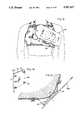
- FIG. 1is a front perspective view of a person operatively wearing an embodiment of the inventive ambulatory physiological evaluation system.
- FIG. 2is a back plan view of the person of FIG. 1 wearing the vest of the subject invention without the electronics package and shoulder strap.
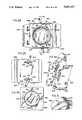
- FIG. 3is a front plan view of the cardiac monitor and mounting bracket for the evaluation system of FIG. 1.
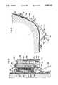
- FIG. 4is a top view partially in section of the evaluation system of FIG. 1.
- FIG. 5is a view taken along line 5--5 of FIG. 3.
- FIG. 6is a plan view of the basic elements constituting the vest of the evaluation system of FIG. 1.
- FIG. 7is a view taken along lines 7--7 of FIG. 6.
- FIG. 8is a view similar to FIG. 4 with the cardiac monitor removed and an alternative embodiment for the detector mounting bracket.
- FIG. 9is a front perspective view of the vest of FIG. 1 with the alignment fixture in place on the detector mounting bracket.
- FIG. 10is a top view of the arrangement of FIG. 9.
- FIG. 11is a plan view of the alignment fixture of FIG. 9.
- FIG. 12is a view taken along lines 12--12 of FIG. 11.
- FIG. 13is an exploded perspective view of an embodiment of the cursor-locating plate.
- FIG. 14is a perspective view of a floating base for use mounting items on the detector mounting plate of FIG. 3.
- FIG. 15is a perspective view of the auxiliary detector used in the evaluation system of FIG. 1.
- FIG. 16is a view taken along lines 16--16 of FIG. 15.
- FIG. 17is a block diagram of the electronic portion of the evaluation system of FIG. 1.
- FIG. 18ais a schematic diagram of a charge coupled amplifier used in the electronic portion of FIG. 17.
- FIG. 18bis a schematic diagram of a positive peak hold circuit used in the electronic portion of FIG. 17.
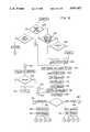
- FIG. 19is a flow chart used to explain the operation of the computer forming part of the evaluation system of FIG. 1.
- FIG. 20is a waveform used in explaining a portion of the operation of the electronic portion of FIG. 17.
- FIGS. 21 and 22are waveforms used in explaining a portion of the operation of the electronic portion of FIG. 17.
- FIGS. 23a-23care waveforms used in explaining a portion of the operation of the electronic portion of FIG. 17.
- FIG. 24is a front perspective view of a modified vest for use in the inventive system.
- FIG. 25is a rear perspective view of a modified vest.
- FIG. 26is a front perspective view of an operative portion of the modified vest with a modified mounting bracket structure and alignment fixture secured to the vest.
- FIG. 27is a sectional view on line 27--27 of FIG. 26.
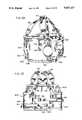
- FIG. 28is a front elevational view of the modified mounting bracket structure.
- FIG. 29is a rear elevational view of the modified mounting bracket structure.
- FIG. 30is a rear elevational view of the modified alignment fixture.
- FIG. 31is an enlarged perspective view of a part of the modified alignment fixture.
- FIG. 32is a sectional view on line 32--32 of FIG. 28.
- FIG. 33is a perspective view of a spring thrust washer used in the modified mounting bracket structure.
- FIG. 34is a front perspective view of a part of the modified vest showing a tear-away feature.
- FIG. 35is a front perspective view similar to FIG. 26 but showing the manner in which a main detector is fitted into the modified mounting structure after removal of the respective alignment fixture.
- the present inventionrelates to an ambulatory physiological evaluation system, generally designated 10, including gamma radiation detectors 12 and 14 utilized in the nuclear medicine field for the purpose of monitoring and/or diagnosing a patient's physiological activities during a prescribed period of time.
- a compact cardiac monitor 11 including a main detector 12is placed generally over the heart of a patient and a radiation detector, mounted within the monitor, senses the ebb and flow of the blood through the heart by detection of the gamma rays emitted by Tc -99m labeled blood cells.
- the radiation detectorIn order to accurately measure blood volume, the radiation detector must be precisely positioned relative to the heart and this relationship must be maintained during the entire detecting period.
- the present inventionprovides an apparatus and method for determining the exact location of the left ventricle, positioning the cardiac monitor relative to the left ventricle, and maintaining the position of the cardiac monitor relative to the left ventricle during an ambulatory study period.
- the starting point for the inventive ambulatory physiological evaluation systemis a vest 16 made of a flexible plastic material, such as Aquaplast, which contains a pattern of ventilation holes 18.
- the vestis adapted to be worn on the torso 20 of a human and contains an arrangement of shoulder straps or shoulder supports 22, 24 and belts 26, 28 to provide for a snug, yet comfortable fit.
- the vestis worn to provide a base to which a detecting assembly in the form of a cardiac monitor 11 is attached and held in a precise relationship between the detecting device and an anatomical body, such as the left ventricle of the heart.
- a detector mounting bracket 30which is a lightweight, formed structure with means for attaching to both the vest and to the detecting device.
- the mounting bracketis made from aluminum, but could be made from plastic or other suitable material.
- the mounting bracketfastens two detecting devices, the main detector 12 and the auxiliary detector 14, to the vest and provides two means for adjusting the main detector relative to the left ventricle of the heart of the wearer.
- the mounting brackethas flanges 32 and 34 so that the bracket can be adjusted relative to the vest through four fasteners 41-44 movably positioned within the vest.
- the main detector 12can be adjusted plus or minus one centimeter in two directions relative to the detector mounting bracket, thereby, providing for a precise adjustment of the main detector relative to the left ventricle of the heart of the wearer.
- a scale 36is provided between the main detector flange and the detector mounting bracket, reading in 5 millimeter increments. The scale precisely indicates the relative position between the mounting bracket and the main detector.
- an alignment fixture 50is used prior to mounting the main detector to the mounting bracket.
- the detector alignment fixturebasically comprises an elongated, planar leveling plate 52 to which is fastened a centering plate 54 within which is embedded a centerline cursor made from lead elements 58.
- the detector alignment fixtureis mounted to the face of the detector mounting bracket with four fasteners, such as cap screws.
- a center guide pin 60 on the alignment fixtureenters a center hole 62 of the detector mounting bracket and in addition the four posts 71-74 on a floating base plate 76 positioned behind the face of the mounting bracket, must enter the four holes in the alignment fixture 54.
- the mounting bracketalso has a pair of opposed, upwardly extending flanges 201 and 203, which aid in aligning and mounting the centering plate. After mounting, the detector alignment fixture is centered and made parallel with the face 162 of the detector mounting plate 30.
- a conventional scintillation or Gamma camera(not shown) is brought up to the alignment fixture and adjusted for parallelism.
- the reason the Gamma camera must be adjusted so that its focal plane is parallel to the face of the alignment fixtureis because the holes of the collimator found in the main detector each have a narrow field of view.
- the picture derived from the Gamma camera on a cathode-ray tube (CRT) display(not shown) shows the position of the cursor 56 relative to the left ventricle of the heart. If the centerline of the cursor is within 10 millimeters of the desired position, any further adjustment can be made when the alignment fixture is removed and the main detector 12 assembled to the mounting bracket. If the location of the centerline is further away from the left ventricle of the heart than 10 millimeters, the mount must be readjusted relative to the vest and the above procedure repeated.
- the ambulatory physiological evaluation system 10also contains electronic circuitry which monitors and processes information obtained from the main and auxiliary detectors.
- a preferred embodiment of the evaluation systembasically comprises a Cadmium Telluride (CdTe) detector 14 which is used as the auxiliary detector that is responsive to the presence of a suitable radio pharmaceutical Tc -99m tagged red blood cells, injected into the circulatory system to provide an output signal representative of left lung or background activity.
- a cardiac monitor 11includes the main detector 12 which is also responsive to the presence of a suitable radiopharmaceutical injected into the circulatory system to produce a signal which is proportional over the cardiac cycle. The signal produced by the main detector is representative of the left ventricular time activity of the heart.
- Both of these signalsare fed in analog pulse form to a data logger which is housed in a bag 80 worn by the patient by way of shoulder strap 81.
- the data loggerincludes the circuitry necessary to accumulate and manipulate the data and transfer it to a portable cassette recording device 82, also housed in the bag.
- feeding information into the recording deviceare conventional ECG electrodes 84. After the information has been recorded over a desired period of time, the recorded information is presented, through a tape player 87 an impedance-matching interface 86 and an analog to digital converter 88, to the memory 90 of a stand alone computer 92 located in a hospital or office.
- the computercalculates and analyzes such items as R--R time interval, electrocardiagram and time-activity curves, and/or displays these items in eye readable form for both the main and auxiliary detectors. From the calculations made by the computer, such items as average heart rate, number of aberrant beats, left ventricular ejection fraction and relative cardiac blood volume may be calculated for a time interval of interest.
- the vest 16consists of a one piece, flexible, thermal plastic material which contains a plurality of ventilation holes 18 arranged in a predetermined pattern to facilitate ventilation between the atmosphere and the skin of the wearer when the vest is in its operative position on the torso as shown in FIGS. 1 and 2.
- the vestis made from a plastic material sold under the name "Aquaplast".
- the vest 16basically comprises an enlarged chest area 92 that fully covers the chest of the wearer, especially in the area of the heart. With reference to its orientation on the torso of a wearer, the lower portion of the vest on either side of the chest terminates in extended strips 94 and 96. Strip 94 passes below the right underarm of the wearer and falls against the small of the back. In like manner, strip 96 passes below the left arm of the wearer and lies against the small of the back. A pair of off-set nylon straps or shoulder supports 26 and 28 are movably positioned within slits 102 and 103 defined on strips 94 and 96, respectively. Each of the straps is secured to the edge of a strip by a series of stitches 104 and terminates in an array of Velcro hooks 106 that mate with a complementary array of Velcro eyes 108 provided on the opposite side of one of the strip portions.
- the strapspass across the back of the wearer to the Velcro fastener located on the opposite strip in order to securely fasten the vest to the patient.
- an emergency separation or release 110Located along a diagonal, at the front of the vest is an emergency separation or release 110 which is created by holding mating sides 112 and 114 of the vest in an abutting relationship and joining them together by a plastic tape or Velcro 116 that is arranged perpendicular to the orientation of the separation line 115.
- Strategically placed guides or planar tabs 113, which are secured to side 114, and guide strip 117 which spans the full length of and is secured to strip 114facilitates placing sides 112 and 114 in abutting relationship.
- the vestcan be quickly released and easily removed through use of the emergency separation 110, which extends diagonally from the right side of the sternum or breastbone near the persons neck downwardly and away from the stomach area toward the right side of the wearer's body.
- the emergency separation 110which extends diagonally from the right side of the sternum or breastbone near the persons neck downwardly and away from the stomach area toward the right side of the wearer's body.
- Also defined on the front of the vestare two large apertures 34 and 36 which define open areas in the 4th and 5th intercoastal spaces for placement of ECG electrodes in conventional manner.
- the bottom periphery 91 of the vestterminates above the right chestwall of the wearer to permit ready placement of the ground ECG electrode.
- each of the shoulder strapshas the same basic configuration with one strap being the mirror image of the other.
- the strapsare generally shaped like an elongated triangle, with the base portion 122 having a hole 124 on one side and a slot 126 on the other side.
- the hole and slotare positioned relative to each other so that they mate with threaded lugs 125 and 127 defined along the upper portion of both sides of the front of the vest.
- the other end 128 of the strapterminates in a slot 132 which receives a belt 134 that is placed in a mating relationship with a slot 138 defined at the end of strip 96.
- Also defined in the strap near the forward endis an aperture 142 configured to reveal a sufficient portion of the skin of the patient in order to receive a conventional ECG electrode.
- straps 22 and 24provide spaces for mounting the two clavicle ECG electrodes.
- the front of the vestin the area covering the heart, are four vertically oriented slots 151 through 154.
- the placement of the slots on the front of the vestis determined in the following manner.
- the front of the vestmay be divided in half along the sternum or breastbone of the wearer.
- the four slotsare defined along the left side of the vest with reference to the sternum.
- the vestcontains a center point 156.
- the slots 151-154exist along a line positioned at about a 10° angle relative to the horizontal plane H through the center point 156.
- Each of the slotsis approximately one inch in length.
- the slotsare oriented perpendicular to the 10° line that is defined through the center point 156.
- Alternate pairs of slots 151-153 and 152-154are approximately 6.76 inches from each other as measured along a line parallel to the 10° line.
- the longitudinal axes of slots 151 and 154are essentially parallel to each other.
- slots 151 through 154are used in connection with the detector mounting bracket 30 to properly position the cardiac monitor 11 and auxiliary detector 14.
- FIGS. 1, 3, and 4show the detector mounting bracket 30 in its position of intended use and mounted on the vest 16.
- the bracketis made from a thin aluminum strip and basically consists of a generally square planar mounting face 162 and a pair of planar mounting flanges 32 and 34.
- an aperture 62which defines a locating hole used in conjunction with the locating pin 60 of a detector alignment fixture 50.
- Also defined at each of the corners of the planar surfaceare larger apertures 171 through 174.
- engraved lines 176Positioned between adjacent apertures along each of the edges of the planar surface are engraved lines 176 which are typically spaced 5 millimeters apart and define scale 36. These lines are engraved on the surface 162 and are used in conjunction with complimentary marks 178 provided on side faces 251 of the main detector 12 in order to properly align the main detector relative to the heart of the wearer.
- FIG. 4shows a top view of the mounting bracket secured to the vest with the cardiac monitor assembly 11 being secured to the mounting bracket.
- the bracket 30has the rear face 182 generally flush with a portion of the vest 16 so that the planar face 162 is generally perpendicular to a line L that passes through a plane P defined along the sternum of the wearer at an angle of approximately 40° to 50° with an angle of 45° being typical. This position is also referred to as the 45° left anterior oblique (LAO) position.
- the outward planar surface 162 of the mounting bracketterminates in an bend 192 that continues in a planar portion 184 which is at an approximately 90° angle to the planar face 162.
- planar portion 184terminates in the flange 32 which is at an approximately 48° angle with reference to the planar portion 162.
- the opposite bend 194 of the planar surface 162meets with a planar portion 196 that is at an approximately 381/2° angle with regard to the planar surface 162.
- Planar portion 196terminates in the flange 34 which is formed at an angle of approximately 141/2° with regard to the planar surface 162.
- Both of the flange portions 32 and 34contain spaced slots 202 which are arranged so that when the detector mounting bracket is positioned on the vest, the longitudinal axes of slots 151 through 154 are generally perpendicular to the longitudinal axes of slots 202 defined on the mounting bracket.
- each of the wing nut assembliesis made up of a wing nut 212 and a threaded portion 214 that terminates at its end in a flat disk 216 which is flush against the interior surface 218 of the vest when the wing nut assemblies are mounted.
- the arrangement of the slots 151 through 154 and 202permit complete two dimensional freedom in positioning the detector mounting bracket relative to the vest.
- the planar position 184is divided up into two overlapping sections 602 and 604 which may move relative to each other to alter the distance from the face 162 to the vest 16.
- the overlapping sectionsare held together by wing nut assemblies 606.
- flange 34meets portion 196 through a hinge 610. In this way, the mounting bracket may be securely fastened with the face 162 at several different mounting angles without placing any bending stress on the mounting bracket.
- the main detector 12is mounted within a housing 330 that has a lower portion 332 generally in the shape of a cylinder and an upper portion 334 generally in the shape of an elongated rectangular solid.
- the housingis made up of upper and lower shells 336 and 338 which are joined together through appropriate fasteners 340 such as pan screws.
- Two photo multiplier tubes 344 and 346are positioned next to each other within the upper housing. The operative ends of the photo multiplier tubes are in intimate contact with a light guiding prism 348 made of leaded glass.
- the lower or cylindrical part of the housinghas a cover plate 350 made of black nylon which is screw mounted onto a cylindrically shaped shield 352. The planar surface of the cover plate defines a detecting plane.
- the part 354 of the shield which receives the coveris of narrower diameter than the remaining portion 356 of the shield.
- the shieldis made of lead with 5% antimony.
- an iris 358Positioned next to the cover is an iris 358 made up of a thin sheet 360 of spring tempered aluminum and a metal ring made from lead with 5% antimony. The iris is optionally used to restrict the field of view in the case of a child's heart or a small adult heart.
- a lead collimator 364Positioned next to the iris is a lead collimator 364 having an array of gamma ray guiding tubes 366. The other side of the collimator is adjacent a sodium iodide (NaI) crystal assembly 368.
- NaIsodium iodide
- a rubber protective gasket 370Between the collimator and the crystal assembly is a rubber protective gasket 370.
- a guide ring 372 made of lead with 5% antimonyis in intimate contact with the lead shield.
- the guide ringreceives and holds a leaded glass window 374 adjacent the NaI crystal.
- Between the glass window 374 and the NaI crystal 368is a very thin layer 375 of epoxy or an RTV silicon rubber.
- the top of the glass windowis in communication with one side of the light prism 348.
- a connector 380having a built-in voltage divider and preamplifier is connected to the photo multiplier tubes.
- the cable 383is connected to the other side of connector 380 and emerges from the housing 338 for connection with the circuitry in bag 80.
- a generally hollow aluminum monitor base 230completes the construction of the main detector.
- the basehas a planar square surface 384 within the center of which is defined a large circular aperture having a diameter sized to receive the narrower portion 354 of shield 352. Also defined within the surface 384 are four mounting holes 231-234. Further details of the construction of the main detector 12 may be found in co-pending U.S. Patent Application Ser. No. 711,096 to Suzuki for High-Energy Radiation Detector and Method of Detection, which is incorporated by reference.
- a floating base plate 76which may be movably retained to the mounting bracket 30 by a suitable means such as a spring or tape.
- the base plateis generally square in configuration with flattened or rounded edges 222 at the corners.
- an aperture 224which is of larger diameter than the aperture defined in the mounting plate.
- a stand-off, 71 through 74which has a vertical axis oriented perpendicular to the planar surface 226 of the base plate.
- Each of the stand-offsis internally threaded.
- the base platelike the mounting bracket is made of aluminum and is positioned behind the planar surface 162 of the mounting bracket in the space defined between the outer surface 228 of the vest and the interior surface 182 of the bracket face so that each of the stand-offs protrude through one of the enlarged apertures 171-174.
- the planar face 226 of the base plateis in intimate contact with the interior face 18 of the mounting bracket.
- the main detector 12is supported on base 230 which contains apertures 231-234 in each of the corners of the base in order to receive the stand-offs 71 through 74 of the floating base plate. Knurled, threaded lugs 241, 242 are then used to secure the base plate and the main detector to the mounting bracket.
- the main detector 12 on the base 230contains four side faces 251, each of which bears index mark 178 which is brought into registry with one of the scales 36 defined about periphery of the surface 162 of the mounting bracket.
- the main detectormay be mounted anywhere on the surface 162 within plus or minus 10 millimeters since each of the scale gradients 176 on the surface 162 are 5 millimeters apart.
- the auxiliary detectorincludes a cylindrically shaped case 601, the floor of which defines a face 603 for the detector.
- the opposite end of the casecontains a threaded portion 605 which mates with a complimentary threaded portion on a cover plate 608.
- the case and the cover platedefine a housing within which is mounted the CdTe detector.
- a printed circuit board 610Positioned within the housing near the cover 608 is a printed circuit board 610 which contains the preamplifier circuitry associated with the detector.
- mounteded in the circuit boardare extended pin contacts 612 and 614.
- a cylindrically shaped hollow lead shield 616is next to the underside of the circuit board.
- an insulator board 618 and alternate carrier boards 620 and 622Positioned within the shield is an insulator board 618 and alternate carrier boards 620 and 622.
- the carrier boardsdefine a square portion 652 which houses a CdTe chip.
- the bottom portion of the shieldreceives a cover 626 which has a circular shape to receive a honeycomb collimator 624.
- the leadsemerge from the cover of the housing for connection to the data logger that is contained in the bag 80.
- the conductive contacts 612 and 614provide electrical contacts with the CdTe chip through the carriers 620 and 622.
- the detectormay be used on various parts of the body, it is desirable to be able to replace and easily remove the detector as desired.
- the face 603 of the detectormay be coated with a double stick tape so that the auxiliary detector may be placed as shown in FIG. 3, on the detector mounting plate or in other locations on both the body and the vest.
- a structure and methodare provided for determining the exact location of the left ventricle and positioning the mounting bracket so that precise placement of the main detector may be insured.
- the main detector 12is secured to the vest through the use of a mounting bracket 30.
- the bracketis a light weight formed metallic structure with a series of slots 202 for attaching the bracket to the vest and a series of enlarged apertures 171-174 for mounting the cardiac monitor.
- the bracketmay be adjustably mounted to the vest and the main detector may be adjustably mounted to the bracket thus providing adjustment of the main detector relative to the left ventricle of the heart within two degrees of freedom.
- An alignment fixture 50is employed in order to properly align the detector mounting bracket relative to the vest.
- the alignment fixtureis generally illustrated in FIGS. 9-14.
- the purpose of the fixtureis to transfer a location of an anatomical body, such as the left ventricle of the heart, utilizing a conventional scintillation camera.
- the alignment fixturemay be described as follows.
- the fixturebasically comprises an elongated planar leveling plate 52 on which is mounted a generally square planar cursor-locating plate 54.
- Both the leveling plate and the cursor plateare preferably made of a transparent plastic material.
- Defined on one side 281 of the mid-portion of the planar leveling plateare a series of four holes 291-294 aligned to receive the stand-offs 71-74 from the floating backing plate 76.
- the cursor or centering plate 54Positioned on one surface 296 of the leveling plate is the cursor or centering plate 54 which also contains four apertures that are brought into alignment with the apertures 291 through 294 defined in the leveling plate.
- the cursor plateactually consists of two planar portions 302 and 304. Sandwiched between these surfaces are an array of lead cursors 58 which aid in aligning the detector mounting bracket relative to the left ventricle of the heart.
- the lead cursorsgenerally consist of lead slugs which are one millimeter thick and 10 millimeters on a side.
- the slugsare arranged within evacuated areas defined on a middle layer 306 in a cross with one cursor 308 being at the center of the cross and two cursors 310 and 312 being on either side of the center cursor on the legs of the cross. Together, the cursors define a centerline.
- cursor 314is 10 millimeters by 20 millimeters and acts as a direction alignment cursor to identify left and right on any image that includes the cursor. It is to be understood that the three layer construction of the cursor plate is for a preferred embodiment and other methods of construction will readily suggest themselves to those skilled in the art.
- Emanating from the central portion of the housingis locating pin 60. This pin is brought into registry with the aperture 62 defined in the mounting bracket.
- suitable fastenerssuch as screw 318 are used to fasten the leveling plate and the housing to the mounting bracket by passing the fastener through the apertures defined in both the leveling plate and the housing. The screws are then secured to the threaded studs provided on the floating backing plate.
- the detector alignment fixtureis now centered on the detector mount.
- a conventional scintillation or Gamma camera(not shown) is brought up to the alignment fixture and adjusted so that the recording plane of the camera is parallel to the face 281 of leveling plate 52.
- the cathode-ray tube display for the scintillation camerashows the position of the lead cursor array 56 relative to the shadow of the left ventricle of the heart. If the center line of the cursor array is within 10 millimeters of the desired position of the left ventricle of the heart any further adjustment can be made with the detector mounting bracket as described hereinbefore. In this case, the alignment fixture may be removed and replaced by the main detector 12.
- the mounting bracketmust be readjusted relative to the vest and the above procedure repeated.
- the adjustment range of the alignment fixture and the mounting bracketmay be altered by changing the distance between gradations on scale 36.
- a vest which fits the patientis selected.
- the detector mounting bracket 30 and the floating base plate 76are secured to the vest.
- the vestis then placed on the patient and the straps are adjusted to eliminate movement of the vest relative to the body of the patient.
- the mounting bracketis adjusted so that it is proximately near the heart, some 40° to 45° clockwise using the sternum or breastbone as a center line.
- a mounting bracket appropriate for the patient's body structureis selected.
- the floating base plate 76is positioned so that the studs 71-74 of the base plate emerge through the large diameter holes 171-174 defined in the mounting bracket.
- the alignment fixtureis aligned so that the long end of the fixture points to the right side of the patients body (when looking at the patient's face).
- the center pin 60 of the alignment fixtureengages the center hole 62 of the mounting bracket.
- the alignment fixtureis then secured to the detector mounting bracket through the captive fasteners.
- the gamma or scintillation camerais then positioned parallel to the face of the alignment fixture and as close as possible to the leveling plate.
- the Gamma camerais activated in order to observe the position of the center line of the alignment fixture relative to the left ventricle of the heart. If the center of the alignment fixture is within 10 millimeters of the center of the left ventricle then the Gamma camera is removed along with the alignment fixture.
- the cardiac monitoris then mounted to the mounting bracket.
- the fasteners between the mount and the vestare loosened and readjusted to reposition the mounting bracket and thus alter the position of the center line so that it is within the 10 millimeters required.
- a preferred embodiment of the evaluation systembasically comprises a Cadmium Telluride (CdTe) detector which is used as the auxiliary detector 14 that is responsive to the presence of a suitable radiopharmaceutical, such as Tc -99m tagged red blood cells, injected into the circulatory system to provide an output signal representative of the left lung time activity.
- the CdTe detector assembly 14consists basically of a CdTe detector 640, a radiation collimator 624, a radiation shield 616, and a preamplifier.
- a cardiac monitor 11 that includes the main detector 12is also responsive to the presence of a suitable radiopharmaceutical injected into the circulatory system, and produces a signal which is proportional to the energy level of radiation emitted by the radiopharmaceutical over the cardiac cycle.
- the signal produced by the main detectoris representative of the left ventricular time activity of the heart.
- Both of these signalsare fed in analog pulse form to a data logger, which is housed in a bag 80 worn by the patient.
- the data loggerincludes the circuitry necessary to accumulate and manipulate the data and transfer it to a portable cassette recording device 82 also housing in the bag.
- feeding information into the recording deviceare conventional EKG electrodes 84. After the information has been recorded over a desired period of time, the recorded information is presented, through a tape player 87, interface 86 and an A/D converter 88, to the memory 90 of stand alone computer 92 located in a hospital or office for later processing and analysis.
- microcomputer 450At the heart of the electrical system is a microcomputer 450.
- the microcomputeris one produced by National Semiconductor and bears the product designation MA2800.
- the microcomputeris a low power, eight bit CMOS microcomputer system. It provides a central processing unit, read only memory 451, random access memory 453, parallel and serial input/output ports, a system clock, programmable timers, and priority interrupt logic.
- the microcomputeris used to control the timing and operation of the other circuitry associated with the ambulatory evaluation system in the manner explained hereinafter.
- FIGS. 17 and 18ashow in greater detail the electronic circuitry associated with the ambulatory ventricular evaluation system.
- a series of Nickel Cadmium batteries 401provide a voltage and current to a voltage regulator 402 in order to provide a regulated 5 volt DC supply 404.
- the 5 volt regulated supplyis used to power up the various circuit elements that make up the evaluation system.
- the 5 volt supplypowers up a high voltage power supply 406 in order to produce a 1000 volt D.C. signal which is used in conjunction with processing the outputs from the two photo multiplier tubes 344 and 346 found in the cardiac monitor 11.
- the outputs from the two photo multiplier tubesare passed through a high speed charge coupled amplifier 408 and then into the negative input of a comparator 410 for discriminating signals.
- the positive input of the comparatorreceives a predetermined reference signal which is typically set at 300 mv. Whenever the output of the high speed charge coupled amplifier exceeds the reference signal, the comparator 410 triggers a one shot multivibrator 412 which further shapes the signal into a four microsecond pulse for introduction into a 16-bit counter 414 which is part of the microcomputer 450.
- the auxiliary detector 14which is a CdTe detector is positioned in an appropriate location for intended study. As shown in FIG. 3, the detector is adjacent to, and to the left of the cardiac monitor 11 on the ambulatory vest 10.
- the auxiliary detector 14produces a signal representative of time activity of the area selected for study. With the detector positioned as shown in FIG. 3, the signal produced is representative of left lung time activity.
- the signalis passed through a charge coupled amplifier 420 and then into a signal discriminator 422.
- the operation of the charged coupled amplifiermay be described as follows.
- the charge coupled amplifieris composed of transistors Q1 through Q4.
- the CdTe detector 14which is biased to 25 volts, produces a charge which is collected at capacitor C4.
- the signalpasses through the front end of the charge coupled amplifier 420 which is a low noise FET amplifier Q6.
- the output of the FETpasses through transistors Q1 and Q2 which are configured as a high impedance constant current load to generate an amplified pulse on lead 425.
- the amplified pulseis fed into the input of a Darlington amplifier made up of transistors Q3 and Q4.
- the output of the Darlington amplifierpasses along lead 427, through capacitor C9 and resistor R12 into a voltage amplifier 430 which produces an output signal of about 40 to 100 millivolts.
- the discriminator 422is used to convert the output of the charged coupled amplifier into a pulse signal for input into a 12-bit counter 432.
- the output of the comparatoris passed to a multivibrator which has been configured as a trigger 436.
- the microcomputertakes the nuclear data information contained in the 16-bit counter and passes it along the data bus 440 to a digital-to-analog converter 442 in a sequence to generate an amplitude modulated signal as described below.
- the counts generated by the background detectorare accumulated in a 12-bit counter 432 for 8 consecutive one second periods. The average of these one second counts is then outputted to the tape recorder on a second track in the format described below. Since the background count is only one of eight possible digital channels the data for each channel is stored and outputted in serial form in the allotted one second slot.
- the informationis recorded on two tracks of the tape recorder.
- One trackrecords the analog information from D/A converter 442 in an Amplitude Modulation format and the other track records the digital average of the analog signal in digital format.
- the microcomputer 450samples the analog signals produced by either the auxiliary detector 14 or the main detector 12 above the Nyquist rate.
- the microcomputeruses the signal from the main detector as exemplary, the microcomputer generates an average digital value based on the previous n samples.
- the number of samples n over which the average is takenis suitably selected so as to optimize the overall frequency response of the signal.
- This digital valueis recorded on one of the channels of the multichannel tape recorder 82.
- Each of the digitized values of the sampled analog signalis then presented to a D/A convertor as a positive magnitude corresponding to the value followed 16 ms later by an equivalent negative value.
- thisis amplitude modulation (A.M.) performed in software.
- An enhancement techniqueis employed to improve the signal-to-noise ratio, whereby a fraction of the average count for the last measurement is subtracted from the current count sample from counter 414. The counting time period determines the carrier frequency of the amplitude modulation.
- FIG. 20shows the same digital sample processed through the D/A convertor with each digital sample being presented as a positive magnitude followed by the equivalent negative magnitude after a time delay of 16 ms. The result is an amplitude modulated wave.
- the demodulator used in a preferred embodimentis a positive peak hold circuit and is shown in FIG. 18b.
- the demodulationis formed as part of the computer 92.
- the demodulatorbasically comprises two operational amplifiers 371 and 373.
- the negative inputs of each amplifierare connected to each other by way of resistor R16.
- the positive input of amplifier 371receives the A.M. signal.
- the output of amplifier 371passes through diode D1 and into the positive input of amplifier 373.
- the output of amplifier 373is fed back to the negative input of amplifier 373 and also defines the output for the demodulated signal.
- the positive input of amplifier 373is connected to ground by way of the parallel arrangement of switch S1 and capacitor C15.
- Each positive peakis held by capacitor C15 until the next positive transition through zero at which point the capacitor charge is dumped via switch S1 which is controlled by computer 92.
- the resultant outputis shown in FIG. 22.
- the amplitude of each of the held peaksrepresents the value of each counting period. These held peaks ultimately are digitized. Since the peaks are held, the exact timing they are digitized is not critical. The process of reconstructing the signal is discussed later.
- the frequency of the carrier signal selectedis, as mention earlier, also the sampling rate. It should be chosen to exceed the Nyquist rate and also lay in the mid-band of the tape recorder's frequency response. Additionally, the carrier frequency is used to synchronously demodulate the signal later on.
- the digital data outputis synchronized to the D/A sampling period. This means that every time a D/A operation is performed on a sample, a bit of serial data from the parallel serial register 444 is subsequently put out under the control of gate 431. Again, the output is in a Return-Through-Zero format. This means a "1" is represented as a positive excursion followed by an equal negative excursion and vice versa for a "0".
- FIGS. 23a-23cshow the timing diagram of both D/A and Digital outputs. The digital data uses phase encoding to generate a "1" or a "0". An example of a sequence 1100110 is shown in FIG. 23a. The digital data is synchronized to the D/A output waveform (FIG. 23b).
- the digital signalcan therefore be demodulated (FIG. 23c) by using the D/A signal as a phase reference.
- the implementation of this phase detectionis done using a sample and hold circuit.
- the digital signalis sampled for the first 1/4 cycle of the reference D/A output and held till the beginning of the next cycle as shown.
- a "1"is represented as positive held voltage; a "0” is represented as a negative held voltage.
- the cassette recorder 82has four tracks capable of recording information.
- the tape speedis typically 2 mm per second and data from the patient may be recorded for up to twenty-four hours.
- the frequency response of the recorderis 0.01-100 hertz at the nominal tape speed.
- Track 1contains the nuclear analog output, which is in the form of left ventricular cardiac Beat-to-Beat analog data.
- the informationis obtained from the D/A converter at a sampling rate of 32 Hz.
- the informationis recorded on track 1 in an amplitude modulated format.
- Track 2records eight groups of digital data.
- the datais processed by the microcomputer 450 and may consists of any or all of the following:
- the eight groups of digital dataare interleaved and a group is outputted every second.
- An identifier codeproceeds each piece of data so that the data may be separated later on. Parity checks are included in the data for error detection.
- the formatis composed of 16-bits of data, with 2-bits of parity. The rest of the time left in the one second transmission is left as a blank. The blank area is useful in determining the beginning of a new word.
- Track three of the recorderis dedicated to record one channel of ECG in standard analog fashion. Track four may be used to record the second ECG signal or another physiological signal, such as blood pressure.
- the cassette tapeis transferred to a four channel audio tape recorder where the data is played back at a speed factor of between 60 and 240.
- the speed-upis necessary in order to bring the frequency of the ECG recording within the band with of the audio tape recorder. Since ECG normally has a frequency spectrum of between 0.05 and 100 Hz, the speed-up ratio of 100 or more is needed.
- the carrier frequency of the nuclear datais used to initiate the triggering of a multichannel A/D converter 88.
- the four channels of the play back recorderare sequentially multiplexed and made available to the high speed A/D converter.
- the A/D convertertransfers the data directly to hard disk by direct memory access. Some filtering and processing of the signals are needed. For these reasons, an anti-aliasing RC filter is required at the output of all four channels.
- the digital data acquired on hard disk memory 90 via the high speed A/D converter 88is sorted out by using tags (identifiers associated with each digital channel), as well as the data sequence itself. Once sorted, the data is compartmentalized and stored as separate files, within the memory of the computer 92.
- the digital samples representing the nuclear analog signalare summed and averaged over an eight second period. These 8 ⁇ 32 samples are bracketed by two digital channel averages (since one average is recorded every eight seconds). The first digital average is used to reestablish the offsets that were subtracted by the front end. This digital offset was generate to enhance the A/C component of the signal as mentioned earlier.
- the current average second digital valueis used as the normalizing factor for the detector counts.
- FIG. 19presents a flow diagram showing the various tasks performed by the software contained in the computer. Initially, the computer is powered up in order to start its operation. A menu appears on the screen with the following choices:
- Selection of the desired functionis made by pressing the appropriate numbered key on the keyboard.
- the first determination to be madeis with regard to inputting patient data (505).
- the computerask the user whether to begin a new patient (500). If the answer is yes, the computer asks "Does data exist for a previous patient?"(502). If the answer is no, then the computer proceeds to Step-Through-Tape-Reader-Set-Up (504).
- the useris stepped through the procedure for setting up the computer's tape reader by prompts appearing on the display 91.
- the systemthen moves onto the Data Acquisition Step 510, where the data is actually obtained from the cassette tape.
- Nuclear and ECG dataare obtained from the analog to digital converter circuitry and then stored in memory by direct memory access. From the memory, the information is stored on disk.
- the computergoes through an archiving protocol (506) where information concerning the previous patient is obtained from a previously recorded file. Certain of the data is then erased (508) and the user is placed into the Step-Through-Tape-Reader-Set-Up. Average data, background data and other digital data are also read in simultaneously and stored in files on a disk.
- the programmay then proceed to Data Reduction 512 where the raw data read in and written to the files is converted into usable data.
- the first aspect of the system programis devoted to the conversion of nuclear data to counts. With regard to ECG data, the program finds each R-wave peak through the use of look-up tables. R-wave peaks and R-to-R intervals are written to a file.
- the system programmay then move on to Gross Analysis 514 and View ECG/Nuclear Data 516 which gives the user an overall view of the data. No user interaction is needed in this section. After the analysis is viewed, the user may chose the regions of data to study in detail.
- ejection fractionwhich may be the measured value or percent of the end diastolic count for each beat. "Filtering” removes some of the statistical fluctuations and the data is easier to view. "Start” is the time to start the analysis, in minutes. “For” is the time period of the analysis, in minutes. “Average” allows the data to be averaged every 15, 30 or 60 seconds. “Running” displays a graph of ejection fraction, heart rate, cardiac output and end diastolic counts.
- buttons from the keyboard 93are:
- Frteringpermits the nuclear data to be viewed with or without filtering. Filtering removes some of the statistical fluctuations and make the data easier to view.
- Startdivides the data into 1 minute groups. Data can only be viewed within a particular 1 minute group.
- Formprovides the number of seconds to view at a time. The limits are between 1 second and 30 seconds, however, the computer will not let you select a time period that goes beyond the end of a minute.
- NN point quadratic smoothing formula
- Data for each beatis smoothed.
- the ejection fractionis found from the maximum and minimum of each heart beat.
- the ejection fraction and R--R intervalare saved in a file for each heart beat.
- presentation branches 530 and 532according to Summed Beats or Beat-to-Beat. In each case, choices for presentation is made via function buttons on keyboard 93. The meaning of the buttons are different in the two cases and their usage is shown on the bottom line of the display screen 91 of the computer.
- the function buttons available on the keyboardinclude:
- the overall datacan be broken up into time periods of interest to the user. Appropriate graphs and histograms may be shown simultaneously.
- the presentation of a new parameterbegins by showing the parameter menu. The following procedure also takes place whenever the New Parameter button is pressed. The parameter is shown as a function of time and as histograms. If the parameter chosen is "waveforms", the summed waveforms are displayed.
- Datais presented for a new region of time (always within the main time region). The user is asked to input the starting and stopping times. The portion of the patient schedule within the main time region is shown to help in the time selection. The data for the current parameter, in the current display type (histogram, graph, or both) is shown. The data for a portion of the current time region is expanded. The user can choose the region by manipulating the graphics cursor using arrow keys, or can input starting and stopping time via the keyboard 93. By pressing the Previous Time Region key, the computer goes back to the previously chosen time region. This is useful in choosing another Sub-region to expand.
- Three types of displaycan be chosen via the keyboard 93: Histogram(s) of the data, graph(s) of the data as a function of time, and combinations of a graph and a histogram.
- the displayis always of the most current parameter using the current time region.
- a copy of the displayis presented on the screen 91 of the computer, along with any needed explanatory messages.
- a tabular summary of the data on the screencan be printed on printer 95.
- Exit from the presentation portionmay be accomplished after confirming that the user really wants to leave the presentation portion.
- the userwill be given the following choices. Beat-to-Beat data for the same time period 540, new overall time period 542, review gross analysis 544, generate final report 546, archive data 548, leave program 550.
- buttons on the keyboardinclude:
- Beat-to-Beat data pointsin order to fit on the graph, are averaged as needed.
- the new average presentationbegins with the selection of a new method of averaging. The following procedure also takes place whenever the New Average button is pressed on the keyboard.
- the useris asked whether the running average is to be taken over a given number of beats or for a given time period. The user then inputs the number of beats or the time period as selected.
- a running average of the ejection fraction and R--R intervalis performed and the results stored in a file.
- a graph and a histogram of ejection fraction and R--R intervalare shown. The parameters may be changed to ejection fraction, R--R interval, or ejection fraction and R--R interval together.
- the rest of the buttonsare the same as for summed data, except that for Exit, the choice is "Summed Data for same time period" 552.
- Auxiliary Dataconsists of the 4 analog inputs plus the second nuclear data counts. This data can be presented along with summed data or Beat-to-Beat data. One or more of these data can be chosen for presentation. In addition, the data can be presented in graphical and/or histogram form without the nuclear cardiac data.
- a final report summarizing selected features of the studymay be generated.
- the current graphic screen or a table formed from that datamay be sent to the printer 95.
- the usermay begin the session by reading in data previously archived (to floppy and/or magnetic tape). The user will then begin the Gross Analysis, and proceed as normal. At the end of the session, data may be archived to disk or tape. This can be used later to review the patient's data. When beginning a session, if any data is on disk, user is asked if it should be archived, since it has to be erased for a new patient.
- the present ambulatory physiological evaluation systemcould be used for real-time on-line data analysis where an information transmission cable is connected from the data logger to the computer 92. In this way, information from the main and auxiliary detectors 12 and 14 could be immediately transferred to computer 92 for real-time analysis and display. It is also contemplated that the bag 80 which carriers the data logger components could be replaced by a belt that would distribute the weight of the components comfortably about the patient's waist.
- FIGS. 24-35show modified versions of the vest, mounting bracket structure and alignment fixture for use in the ambulatory evaluation system in accordance with the invention.
- Vest 600which may be used in place of the vest 16.
- Vest 600may again be made of a ventilated flexible plastic material such as Aquaplast, as in the previously described embodiment, and may be similarly shaped with a relatively wide chest-encompassing front section 602, which tapers downwardly at the top so as to fit under the arms and provide extended rear end portions 604, 606 of narrower width.
- the vestmay be edged with a padded material edging 608 of foam rubber, plastic or the like.
- the vestmay have criss-cross adjustable padded shoulder straps 610, 612 which may be releasably secured at the front of the vest, for example by snap fasteners 614 and which have buckle-type adjusters 616 of known type.
- the vestfurther has adjustable length back straps 618, 620 with Velcro-type attachments 622, 624 for securing same around a patient's body in similar manner to straps 26, 28 of the previous embodiment. Buckles 626, 628 may be used to adjust the length of the straps to tighten or loosen the vest when it is on without releasing the Velcro fastenings.
- vest 600has a circular aperture 630 (FIG. 24) for positioning over a patient's heart in like manner to aperture 36 of vest 16, and vertically extending slots 632, 634, 636, 638 related in located to aperture 630 in like manner to the slots 151-154 of the previous embodiment for adjustably attaching a mounting bracket structure to the vest.
- the vesthas a quick-release breakaway opening on the right hand side (see FIG. 34 in particular) effectively splitting the front section 602 of the vest into left and right hand segments 602L, 602R which are normally held together by quick-release snap fasteners 640.
- An identification tab 642may be provided adjacent to the quick-release opening.
- vest 600can be used in place of vest 16 with the mounting bracket structure and alignment fixture as previously described. Preferably, however, vest 600 may be used with the modified mounting structure and alignment fixture shown in FIGS. 26-33, and 35, as will now be described.
- Base plate 646has mutually angled flanges 646a and 646b, flange 646a having substantially horizontal slots 658 whereby the plate may be adjustably secured in slots 632, 634 of vest 600 by threaded stud-type connectors 660 as in the previous embodiment.
- Base plate 648has a vest connection flange 648a with slots 662 for adjustable securement in vest slots 636, 638 by further threaded connectors 660, and a further angled connection flange 648b at its opposite end for securement to plate 646 by means of still further threaded connectors 660. While not evident in the drawings, one of the plate flanges 646b or 648b may be slotted to allow a degree of adjustment as between the respective base plates.
- the plate 648has a substantially planar central portion 648c for mounting plate 650.
- Central portion 648cis formed with forwardly projecting upper and lower edge flanges 662, 664, and spaced elongate horizontal slots 666, 668 (see FIG. 29).
- the base plates 646, 648may be of a light weight construction made of materials generally as described in connection with the previous embodiment.
- Mounting plate 650may be of generally rectangular form with beveled corners and fits between the edge flanges 662, 664. As best seen in FIG. 32, the mounting plate is provided with upper and lower rearwardly projecting threaded pins 670 which fit in the respective slots 666, 668 to allow the position of the mounting plate to be adjusted laterally on the central portion 648c of plate 648. Screws 672 with operating levers 674 are provided on pins 670 to tighten the mounting plate in position and the levers are provided with angled plastic shrink-on caps 675 which protrude forwardly and prevent the levers from dropping behind plate 648 and becoming inaccessible. The pitch of the pin and screw threads is such that only a few degrees of lever movement is required to lock and unlock the mounting plate.
- a ball socket support ring 677Secured on the outer surface of mounting plate 650 by any suitable means such as adhesive or threaded connectors, is a ball socket support ring 677 which has a series of integrally formed forwardly extending flexible fingers 676, which extend over a circumference of about 315°-330°, the fingers being somewhat concave in profile (see FIGS. 27 and 32) and forming a part cup-like retainer for a similarly profiled generally cylindrical ball socket 678, conveniently made of a hard plastic material.
- the flexible fingers 676 and the ball socket 678have complimentary concave-convex, inner and outer surfaces whereby the socket can swivel axially within the fingers and can also be rotated circumferentially.
- the ball socketcan be locked in position within the retaining fingers by a locking mechanism comprising a substantially inextensible tightening strap 680 which circumferentially surrounds the fingers 676.
- a locking mechanismcomprising a substantially inextensible tightening strap 680 which circumferentially surrounds the fingers 676.
- One end of strap 680is fixedly secured to a fitting 682 on the exterior of ring 674, and the other end of the strap is secured to a retaining band 684 itself attached at a pivot connection 686 (FIG. 28) to an over-center, toggle-type latching lever 688 mounted on a support 690 also carried by ring 674.
- socket 678has a stepped profile (see particularly FIG. 32) with a circumferential rebated groove 690 toward its inner end and three equally peripherally spaced channels 692 (only one of which is shown in FIG. 32) in the inner peripheral wall of the socket leading into groove 690.
- a thrust washer 694 having a wave-like profileis located in groove 690.
- socket 678is adapted selectively to receive the alignment fixture 654 and the main detector device 656.
- the alignment fixture 654(see FIGS. 27, 30 and 31) comprises a generally cylindrical body portion 696 to fit in the ball socket 678, and an outer plate portion 698 to provide a datum surface for a Gamma camera as previously described in connection with plate 52 of the previous embodiment.
- the cylindrical body portion 698has a peripheral ring 700 provided with three equally interspaced projecting tabs 702 to align with and engage in the previously referred to channels 692 in the socket. To releasably fix the fitting in the socket, the tabs 702 are pushed down the channels 692 until they engage and resiliently depress the thrust washing 694.
- the alignment fittinghas a first array of lead inlay elements 706 defining an orthogonal biaxial cursor of the type described in connection with FIGS. 11-13 of the previous embodiment, and a similar sandwich-type cursor structure can be incorporated at the inner end 74 of the alignment fitting.
- outer plate portion 698 of the alignment fittingmay be made of a similar sandwich-type construction incorporating a second array of lead inlay elements 708 disposed orthogonally as extensions of the first array when viewed in plan as in FIG. 30.
- the cursor array of lead elements 706, 708may be used in conjunction with a Gamma camera placed on plate portion 698 generally in a similar manner to the previously described embodiment in locating and targeting an organic target such as a patient's left ventricle.
- a Gamma cameraplaced on plate portion 698 generally in a similar manner to the previously described embodiment in locating and targeting an organic target such as a patient's left ventricle.
- the main detector device 656(FIG. 35) is generally similar to the main detector 11 described in connection with the previous embodiment. In this case, however, the detector has a cylindrical body portion with projecting tabs 710 corresponding to the tabs 702 of the alignment fitting, for engagement in the channels 692 of the ball socket 678, whereby the detector can be attached to and detached from the ball socket in like manner to the attachment and detachment of the alignment fitting.
- the alignment fittingwill be inserted in the ball socket, and used in conjunction with a Gamma camera as in the first embodiment accuratetly to target the patient's left ventricle, using the available adjustments of the mounting structure, namely the lateral movement available to mounting plates 650, the angular adjustments available in base plates 646, 648, and the swivel adjustment available by movement of the ball socket 678.
- the various adjustment mechanismsincluding strap 680 which locks the ball socket in place, are tightened down, and the alignment fitting is then replaced by the detector device. It is evident that the modified structure has a greater flexibility of adjustment than the previous embodiment.
Landscapes
- Health & Medical Sciences (AREA)
- Life Sciences & Earth Sciences (AREA)
- Cardiology (AREA)
- Heart & Thoracic Surgery (AREA)
- Molecular Biology (AREA)
- Veterinary Medicine (AREA)
- Biophysics (AREA)
- Pathology (AREA)
- Engineering & Computer Science (AREA)
- Biomedical Technology (AREA)
- Public Health (AREA)
- Medical Informatics (AREA)
- Physics & Mathematics (AREA)
- Surgery (AREA)
- Animal Behavior & Ethology (AREA)
- General Health & Medical Sciences (AREA)
- Hematology (AREA)
- Physiology (AREA)
- Measurement And Recording Of Electrical Phenomena And Electrical Characteristics Of The Living Body (AREA)
- Nuclear Medicine (AREA)
- Measuring Pulse, Heart Rate, Blood Pressure Or Blood Flow (AREA)
- Professional, Industrial, Or Sporting Protective Garments (AREA)
Abstract
Description
Claims (9)
Priority Applications (10)
| Application Number | Priority Date | Filing Date | Title |
|---|---|---|---|
| US07/096,521US5007427A (en) | 1987-05-07 | 1987-09-15 | Ambulatory physiological evaluation system including cardiac monitoring |
| JP63507978AJP2701907B2 (en) | 1987-09-15 | 1988-08-18 | Exercise physiology evaluation system including heart monitor function |
| SU884743715ARU2080819C1 (en) | 1987-09-15 | 1988-08-18 | Jacket for using in physiological evaluation system |
| AU25280/88AAU2528088A (en) | 1987-09-15 | 1988-08-18 | Ambulatory physiological evaluation system including cardiac monitoring |
| KR1019890700861AKR890701056A (en) | 1987-09-15 | 1988-08-18 | Mobility Physiological Evaluation System with Cardiac Monitoring |
| PCT/US1988/002739WO1989002246A1 (en) | 1987-09-15 | 1988-08-18 | Ambulatory physiological evaluation system including cardiac monitoring |
| EP19880908823EP0393063A4 (en) | 1987-09-15 | 1988-08-18 | Ambulatory physiological evaluation system including cardiac monitoring |
| KR1019890700861AKR920005638B1 (en) | 1987-09-15 | 1988-08-18 | Mobility physiological evaluation device with cardiac monitoring function |
| US07/395,082US5072458A (en) | 1987-05-07 | 1989-08-17 | Vest for use in an ambulatory physiological evaluation system including cardiac monitoring |
| US07/520,405US5111818A (en) | 1985-10-08 | 1990-05-08 | Ambulatory physiological evaluation system including cardiac monitoring |
Applications Claiming Priority (2)
| Application Number | Priority Date | Filing Date | Title |
|---|---|---|---|
| US07/046,854US4920969A (en) | 1985-10-08 | 1987-05-07 | Ambulatory physiological evaluation system including cardiac monitoring |
| US07/096,521US5007427A (en) | 1987-05-07 | 1987-09-15 | Ambulatory physiological evaluation system including cardiac monitoring |
Related Parent Applications (1)
| Application Number | Title | Priority Date | Filing Date |
|---|---|---|---|
| US07/046,854Continuation-In-PartUS4920969A (en) | 1985-10-08 | 1987-05-07 | Ambulatory physiological evaluation system including cardiac monitoring |
Related Child Applications (2)
| Application Number | Title | Priority Date | Filing Date |
|---|---|---|---|
| US07/395,082Continuation-In-PartUS5072458A (en) | 1987-05-07 | 1989-08-17 | Vest for use in an ambulatory physiological evaluation system including cardiac monitoring |
| US07/520,405DivisionUS5111818A (en) | 1985-10-08 | 1990-05-08 | Ambulatory physiological evaluation system including cardiac monitoring |
Publications (1)
| Publication Number | Publication Date |
|---|---|
| US5007427Atrue US5007427A (en) | 1991-04-16 |
Family
ID=22257747
Family Applications (1)
| Application Number | Title | Priority Date | Filing Date |
|---|---|---|---|
| US07/096,521Expired - LifetimeUS5007427A (en) | 1985-10-08 | 1987-09-15 | Ambulatory physiological evaluation system including cardiac monitoring |
Country Status (7)
| Country | Link |
|---|---|
| US (1) | US5007427A (en) |
| EP (1) | EP0393063A4 (en) |
| JP (1) | JP2701907B2 (en) |
| KR (1) | KR890701056A (en) |
| AU (1) | AU2528088A (en) |
| RU (1) | RU2080819C1 (en) |
| WO (1) | WO1989002246A1 (en) |
Cited By (186)
| Publication number | Priority date | Publication date | Assignee | Title |
|---|---|---|---|---|
| US5072458A (en)* | 1987-05-07 | 1991-12-17 | Capintec, Inc. | Vest for use in an ambulatory physiological evaluation system including cardiac monitoring |
| US5224479A (en)* | 1991-06-21 | 1993-07-06 | Topy Enterprises Limited | ECG diagnostic pad |
| US5263925A (en)* | 1991-07-22 | 1993-11-23 | Gilmore Jr Thomas F | Photopheresis blood treatment |
| US5293840A (en)* | 1993-01-22 | 1994-03-15 | Susan Wedlick | Laboratory animal restraining jacket with a sealable medical device holding pocket |
| US5416310A (en)* | 1993-05-28 | 1995-05-16 | Symbol Technologies, Inc. | Computer and/or scanner system incorporated into a garment |
| US5438985A (en)* | 1993-01-25 | 1995-08-08 | Synectics Medical, Incorporated | Ambulatory recording of the presence and activity of substances in gastro-intestinal compartments |
| US5477860A (en)* | 1992-11-05 | 1995-12-26 | Synectics Medical, Inc. | Catheter for measuring respiration and respiratory effort |
| US5477854A (en)* | 1993-09-16 | 1995-12-26 | Synectics Medical, Inc. | System and method to monitor gastrointestinal Helicobacter pylori infection |
| US5479935A (en)* | 1993-10-21 | 1996-01-02 | Synectics Medical, Inc. | Ambulatory reflux monitoring system |
| US5491651A (en)* | 1992-05-15 | 1996-02-13 | Key, Idea Development | Flexible wearable computer |
| US5507289A (en)* | 1993-09-16 | 1996-04-16 | Synectics Medical, Inc. | System and method to diagnose bacterial growth |
| US5551425A (en)* | 1993-05-13 | 1996-09-03 | Synectics Medical, Inc. | Potential difference and perfusion pressure catheter |
| US5555490A (en)* | 1993-12-13 | 1996-09-10 | Key Idea Development, L.L.C. | Wearable personal computer system |
| US5572401A (en)* | 1993-12-13 | 1996-11-05 | Key Idea Development L.L.C. | Wearable personal computer system having flexible battery forming casing of the system |
| US5657759A (en)* | 1993-05-13 | 1997-08-19 | Synectics Medical, Incorporated | Measurement of gastric emptying and gastrointestinal output |
| US5742060A (en)* | 1994-12-23 | 1998-04-21 | Digirad Corporation | Medical system for obtaining multiple images of a body from different perspectives |
| US5786597A (en)* | 1994-12-23 | 1998-07-28 | Digirad Corporation | Semiconductor gamma-ray camera and medical imaging system |
| US5810741A (en)* | 1992-11-05 | 1998-09-22 | Synectics Medical Ab | Method of measuring respiration and respiratory effort using plural catheters |
| WO1998041279A1 (en)* | 1997-03-17 | 1998-09-24 | Nims, Inc. | Physiologic signs feedback system |
| US5833625A (en)* | 1993-10-21 | 1998-11-10 | Synectics Medical Ab | Ambulatory reflux monitoring system |
| US5967983A (en)* | 1995-10-31 | 1999-10-19 | Digirad Corporation | Apparatus for securing a medical imaging device to a body |
| EP0956814A1 (en) | 1998-03-18 | 1999-11-17 | Capintec Inc., | Mesuring cardiac ejection fraction by radiation |
| US6014578A (en)* | 1998-08-06 | 2000-01-11 | Meotronic, Inc. | Ambulatory recorder having method of configuring size of data subject to loss in volatile memory |
| US6055450A (en)* | 1994-12-23 | 2000-04-25 | Digirad Corporation | Bifurcated gamma camera system |
| US6065154A (en)* | 1998-04-07 | 2000-05-23 | Lifecor, Inc. | Support garments for patient-worn energy delivery apparatus |
| US6076003A (en)* | 1998-05-01 | 2000-06-13 | R.Z. Comparative Diagnostics Ltd. | Electrocardiography electrodes holder and monitoring set |
| US6077223A (en)* | 1998-08-06 | 2000-06-20 | Medtronic, Inc. | Ambulatory recorder having control screen to present dual interface for dual users |
| US6097607A (en)* | 1996-11-01 | 2000-08-01 | Via, Inc. | Flexible computer system |
| US6115622A (en)* | 1998-08-06 | 2000-09-05 | Medtronic, Inc. | Ambulatory recorder having enhanced sampling technique |
| US6119029A (en)* | 1998-08-06 | 2000-09-12 | Medtronic, Inc. | Ambulatory recorder having splash resistant sensor ports |
| US6128520A (en)* | 1998-08-06 | 2000-10-03 | Medtronic, Inc. | Ambulatory recorder having volatile and non-volatile memories |
| US6141574A (en)* | 1998-08-06 | 2000-10-31 | Medtronic, Inc. | Ambulatory recorder having sliding period switches |
| US6142938A (en)* | 1998-08-06 | 2000-11-07 | Medtronic Inc. | Ambulatory data recorder having ergonomically shaped housing |
| US6154668A (en)* | 1998-08-06 | 2000-11-28 | Medtronics Inc. | Ambulatory recorder having a real time and non-real time processors |
| US6200264B1 (en) | 1998-08-06 | 2001-03-13 | Medtronic Inc. | Ambulatory recorder having wireless data transfer with a multi-plane lens |
| US6224548B1 (en) | 1998-05-26 | 2001-05-01 | Ineedmd.Com, Inc. | Tele-diagnostic device |
| US6245013B1 (en) | 1998-12-14 | 2001-06-12 | Medtronic, Inc. | Ambulatory recorder having synchronized communication between two processors |
| US6248064B1 (en) | 1998-05-26 | 2001-06-19 | Ineedmd.Com,Inc. | Tele-diagnostic device |
| US6258028B1 (en)* | 1999-02-12 | 2001-07-10 | Medison Co., Ltd. | Portable ultrasonic diagnostic apparatus for veterinary activity |
| US6285909B1 (en) | 1999-05-27 | 2001-09-04 | Cardiac Pacemakers, Inc. | Preserving patient specific data in implantable pulse generator systems |
| US6370432B1 (en) | 1999-08-20 | 2002-04-09 | Cardiac Pacemakers, Inc. | Pacemaker passive measurement testing system and method |
| US20020045805A1 (en)* | 1998-05-26 | 2002-04-18 | Ineedmd.Com,Inc. | Tele-diagnostic device |
| US6516289B2 (en)* | 1999-07-21 | 2003-02-04 | Daniel David | Physiological measuring system comprising a garment and sensing apparatus incorporated in the garment |
| US6527718B1 (en)* | 1999-08-20 | 2003-03-04 | Brian G Connor | Ultrasound system for continuous imaging and delivery of an encapsulated agent |
| US20030101508A1 (en)* | 2000-06-06 | 2003-06-05 | Marshall Peter Alan | Load carrying assembly |
| US20030120135A1 (en)* | 1998-05-26 | 2003-06-26 | Govindan Gopinathan | Method for remote medical consultation and care |
| US20030125623A1 (en)* | 2000-10-13 | 2003-07-03 | Sonocine, Inc. | Ultrasonic cellular tissue screening tool |
| US20030135127A1 (en)* | 2000-04-17 | 2003-07-17 | Vivometrics, Inc. | Systems and methods for ambulatory monitoring of physiological signs |
| US6605038B1 (en) | 2000-06-16 | 2003-08-12 | Bodymedia, Inc. | System for monitoring health, wellness and fitness |
| US20030176183A1 (en)* | 2001-04-02 | 2003-09-18 | Therasense, Inc. | Blood glucose tracking apparatus and methods |
| US20030216786A1 (en)* | 1999-12-14 | 2003-11-20 | Joseph Russial | Circuit for producing an arbitrary defibrillation waveform |
| US20030233039A1 (en)* | 2002-06-12 | 2003-12-18 | Lingxiong Shao | Physiological model based non-rigid image registration |
| US6728576B2 (en) | 2001-10-31 | 2004-04-27 | Medtronic, Inc. | Non-contact EKG |
| US6757556B2 (en) | 1998-05-26 | 2004-06-29 | Ineedmd. Com | Electrode sensor |
| US20040152957A1 (en)* | 2000-06-16 | 2004-08-05 | John Stivoric | Apparatus for detecting, receiving, deriving and displaying human physiological and contextual information |
| US20040249999A1 (en)* | 2003-04-04 | 2004-12-09 | Connolly Brian Edmond | Method and system for transferring analyte test data |
| US20040249299A1 (en)* | 2003-06-06 | 2004-12-09 | Cobb Jeffrey Lane | Methods and systems for analysis of physiological signals |
| US20050003470A1 (en)* | 2003-06-10 | 2005-01-06 | Therasense, Inc. | Glucose measuring device for use in personal area network |
| US6847836B1 (en) | 2002-02-08 | 2005-01-25 | Lenny Sujdak | Emergency ECG electrode chest pad |
| US6850791B1 (en)* | 2000-12-26 | 2005-02-01 | Axelgaard Manufacturing Co. Ltd. | Compress garment with cover for electrodes |
| US20050240087A1 (en)* | 2003-11-18 | 2005-10-27 | Vivometrics Inc. | Method and system for processing data from ambulatory physiological monitoring |
| US20050245839A1 (en)* | 2002-08-22 | 2005-11-03 | John Stivoric | Non-invasive temperature monitoring device |
| US20060031102A1 (en)* | 2000-06-16 | 2006-02-09 | Bodymedia, Inc. | System for detecting, monitoring, and reporting an individual's physiological or contextual status |
| US20060036183A1 (en)* | 2002-03-26 | 2006-02-16 | Vivometrics Inc. | Method and system for extracting cardiac parameters from plethysmographic signals |
| US7020508B2 (en) | 2002-08-22 | 2006-03-28 | Bodymedia, Inc. | Apparatus for detecting human physiological and contextual information |
| US20060122528A1 (en)* | 2004-09-21 | 2006-06-08 | Yoav Gal | Sensors for inductive plethysmographic monitoring applications and apparel using same |
| US20060122474A1 (en)* | 2000-06-16 | 2006-06-08 | Bodymedia, Inc. | Apparatus for monitoring health, wellness and fitness |
| US20060178591A1 (en)* | 2004-11-19 | 2006-08-10 | Hempfling Ralf H | Methods and systems for real time breath rate determination with limited processor resources |
| US20060224051A1 (en)* | 2000-06-16 | 2006-10-05 | Bodymedia, Inc. | Wireless communications device and personal monitor |
| US20060241704A1 (en)* | 2005-04-25 | 2006-10-26 | Allan Shuros | Method and apparatus for pacing during revascularization |
| US20060259087A1 (en)* | 2005-05-13 | 2006-11-16 | Baynham Tamara C | Method and apparatus for cardiac protection pacing |
| US20060258914A1 (en)* | 2005-04-20 | 2006-11-16 | Derchak P A | Systems and methods for non-invasive physiological monitoring of non-human animals |
| US20060259088A1 (en)* | 2005-05-13 | 2006-11-16 | Pastore Joseph M | Method and apparatus for delivering pacing pulses using a coronary stent |
| US20060276717A1 (en)* | 2003-08-13 | 2006-12-07 | Iden Mossanen-Shams | Pulmonary evaluation device |
| US20060282000A1 (en)* | 2005-06-08 | 2006-12-14 | Cardiac Pacemakers, Inc. | Ischemia detection using a heart sound sensor |
| US20060287684A1 (en)* | 2005-05-13 | 2006-12-21 | Baynham Tamara C | Method and apparatus for initiating and delivering cardiac protection pacing |
| US20070021789A1 (en)* | 2005-01-06 | 2007-01-25 | Pastore Joseph M | Intermittent stress augmentation pacing for cardioprotective effect |
| US20070038382A1 (en)* | 2005-08-09 | 2007-02-15 | Barry Keenan | Method and system for limiting interference in electroencephalographic signals |
| US20070038038A1 (en)* | 1999-10-18 | 2007-02-15 | Bodymedia, Inc. | Wearable human physiological and environmental data sensors and reporting system therefor |
| US20070043393A1 (en)* | 2005-08-19 | 2007-02-22 | Cardiac Pacemakers, Inc. | Method and apparatus for delivering chronic and post-ischemia cardiac therapies |
| US20070049843A1 (en)* | 2005-05-20 | 2007-03-01 | Derchak P A | Methods and systems for determining dynamic hyperinflation |
| US20070050715A1 (en)* | 2005-07-26 | 2007-03-01 | Vivometrics, Inc. | Computer interfaces including physiologically guided avatars |
| US20070150005A1 (en)* | 2005-12-23 | 2007-06-28 | Sih Haris J | Method and apparatus for tissue protection against ischemia using remote conditioning |
| US20070177770A1 (en)* | 2006-01-30 | 2007-08-02 | Derchak P A | System and method for identity confirmation using physiologic biometrics to determine a physiologic fingerprint |
| US7261690B2 (en) | 2000-06-16 | 2007-08-28 | Bodymedia, Inc. | Apparatus for monitoring health, wellness and fitness |
| US20070209669A1 (en)* | 2006-03-09 | 2007-09-13 | Derchak P Alexander | Monitoring and quantification of smoking behaviors |
| US20070270671A1 (en)* | 2006-04-10 | 2007-11-22 | Vivometrics, Inc. | Physiological signal processing devices and associated processing methods |
| US20070287896A1 (en)* | 2006-06-08 | 2007-12-13 | Derchak P A | System and method for snore detection and confirmation |
| US20070293781A1 (en)* | 2003-11-04 | 2007-12-20 | Nathaniel Sims | Respiration Motion Detection and Health State Assesment System |
| US20080015454A1 (en)* | 2005-09-21 | 2008-01-17 | Yoav Gal | Band-like garment for physiological monitoring |
| US20080027341A1 (en)* | 2002-03-26 | 2008-01-31 | Marvin Sackner | Method and system for extracting cardiac parameters from plethysmographic signals |
| US20080082018A1 (en)* | 2003-04-10 | 2008-04-03 | Sackner Marvin A | Systems and methods for respiratory event detection |
| US20080177191A1 (en)* | 2007-01-19 | 2008-07-24 | Cardiac Pacemakers, Inc. | Ischemia detection using heart sound timing |
| US20080183090A1 (en)* | 2003-09-12 | 2008-07-31 | Jonathan Farringdon | Method and apparatus for measuring heart-related parameters and deriving human status parameters from sensed physiological and contextual parameters |
| US20080221636A1 (en)* | 2007-03-06 | 2008-09-11 | Cardiac Pacemakers, Inc. | Method and apparatus for closed-loop intermittent cardiac stress augmentation pacing |
| US20080255468A1 (en)* | 2005-04-20 | 2008-10-16 | Derchak P Alexander | Systems and methods for non-invasive physiological monitoring of non-human animals |
| US20080319796A1 (en)* | 2007-02-16 | 2008-12-25 | Stivoric John M | Medical applications of lifeotypes |
| US20090177068A1 (en)* | 2002-10-09 | 2009-07-09 | Stivoric John M | Method and apparatus for providing derived glucose information utilizing physiological and/or contextual parameters |
| US20090192560A1 (en)* | 2008-01-29 | 2009-07-30 | Cardiac Pacemakers, Inc | Configurable intermittent pacing therapy |
| US20090234401A1 (en)* | 2008-03-17 | 2009-09-17 | Zielinski John R | Deactivation of intermittent pacing therapy |
| US20090234416A1 (en)* | 2008-03-11 | 2009-09-17 | Zielinski John R | Intermittent pacing therapy delivery statistics |
| US20090281394A1 (en)* | 2006-09-25 | 2009-11-12 | Brian Keith Russell | Bio-mechanical sensor system |
| US7620438B2 (en) | 2006-03-31 | 2009-11-17 | Abbott Diabetes Care Inc. | Method and system for powering an electronic device |
| US20090318989A1 (en)* | 2008-06-19 | 2009-12-24 | Tomaschko Daniel K | Pacing catheter with stent electrode |
| US20090318994A1 (en)* | 2008-06-19 | 2009-12-24 | Tracee Eidenschink | Transvascular balloon catheter with pacing electrodes on shaft |
| US20090318749A1 (en)* | 2008-06-19 | 2009-12-24 | Craig Stolen | Method and apparatus for pacing and intermittent ischemia |
| US20090318984A1 (en)* | 2008-06-19 | 2009-12-24 | Mokelke Eric A | External pacemaker with automatic cardioprotective pacing protocol |
| US20090318992A1 (en)* | 2008-06-19 | 2009-12-24 | Tracee Eidenschink | Pacing catheter releasing conductive liquid |
| US20090318993A1 (en)* | 2008-06-19 | 2009-12-24 | Tracee Eidenschink | Pacemaker integrated with vascular intervention catheter |
| US20090318991A1 (en)* | 2008-06-19 | 2009-12-24 | Tomaschko Daniel K | Pacing catheter for access to multiple vessels |
| US20100056858A1 (en)* | 2008-09-02 | 2010-03-04 | Mokelke Eric A | Pacing system for use during cardiac catheterization or surgery |
| US20100130913A1 (en)* | 2006-08-31 | 2010-05-27 | Tamara Colette Baynham | Integrated catheter and pulse generator systems and methods |
| US7727161B2 (en) | 2003-04-10 | 2010-06-01 | Vivometrics, Inc. | Systems and methods for monitoring cough |
| US7766829B2 (en) | 2005-11-04 | 2010-08-03 | Abbott Diabetes Care Inc. | Method and system for providing basal profile modification in analyte monitoring and management systems |
| US7774057B2 (en) | 2005-09-06 | 2010-08-10 | Cardiac Pacemakers, Inc. | Method and apparatus for device controlled gene expression for cardiac protection |
| US20100251454A1 (en)* | 2009-04-03 | 2010-10-07 | Pamela Kiernan | Garments for providing access for sensors to contact skin |
| US7811231B2 (en) | 2002-12-31 | 2010-10-12 | Abbott Diabetes Care Inc. | Continuous glucose monitoring system and methods of use |
| US20100274100A1 (en)* | 2004-06-18 | 2010-10-28 | Andrew Behar | Systems and methods for monitoring subjects in potential physiological distress |
| US20100305648A1 (en)* | 2009-05-28 | 2010-12-02 | Shantha Arcot-Krishnamurthy | Method and apparatus for safe and efficient delivery of cardiac stress augmentation pacing |
| US7860544B2 (en) | 1998-04-30 | 2010-12-28 | Abbott Diabetes Care Inc. | Analyte monitoring device and methods of use |
| US20110071584A1 (en)* | 2009-09-23 | 2011-03-24 | Mokelke Eric A | Method and apparatus for automated control of pacing post-conditioning |
| US7920907B2 (en) | 2006-06-07 | 2011-04-05 | Abbott Diabetes Care Inc. | Analyte monitoring system and method |
| US7928850B2 (en) | 2007-05-08 | 2011-04-19 | Abbott Diabetes Care Inc. | Analyte monitoring system and methods |
| US20110106197A1 (en)* | 2009-10-30 | 2011-05-05 | Shantha Arcot-Krishnamurthy | Pacemaker with vagal surge monitoring and response |
| US8000780B2 (en) | 2006-06-27 | 2011-08-16 | Cardiac Pacemakers, Inc. | Detection of myocardial ischemia from the time sequence of implanted sensor measurements |
| US20110224530A1 (en)* | 1999-07-21 | 2011-09-15 | Daniel David | Physiological Measuring System Comprising a Garment in the Form of a Sleeve or Glove and Sensing Apparatus Incorporated in the Garment |
| US8103456B2 (en) | 2009-01-29 | 2012-01-24 | Abbott Diabetes Care Inc. | Method and device for early signal attenuation detection using blood glucose measurements |
| US8108034B2 (en) | 2005-11-28 | 2012-01-31 | Cardiac Pacemakers, Inc. | Systems and methods for valvular regurgitation detection |
| US8112240B2 (en) | 2005-04-29 | 2012-02-07 | Abbott Diabetes Care Inc. | Method and apparatus for providing leak detection in data monitoring and management systems |
| US8123686B2 (en) | 2007-03-01 | 2012-02-28 | Abbott Diabetes Care Inc. | Method and apparatus for providing rolling data in communication systems |
| US8149117B2 (en) | 2007-05-08 | 2012-04-03 | Abbott Diabetes Care Inc. | Analyte monitoring system and methods |
| US8226891B2 (en) | 2006-03-31 | 2012-07-24 | Abbott Diabetes Care Inc. | Analyte monitoring devices and methods therefor |
| US8287454B2 (en) | 1998-04-30 | 2012-10-16 | Abbott Diabetes Care Inc. | Analyte monitoring device and methods of use |
| US8346337B2 (en) | 1998-04-30 | 2013-01-01 | Abbott Diabetes Care Inc. | Analyte monitoring device and methods of use |
| US8398546B2 (en) | 2000-06-16 | 2013-03-19 | Bodymedia, Inc. | System for monitoring and managing body weight and other physiological conditions including iterative and personalized planning, intervention and reporting capability |
| US8456301B2 (en) | 2007-05-08 | 2013-06-04 | Abbott Diabetes Care Inc. | Analyte monitoring system and methods |
| US8465425B2 (en) | 1998-04-30 | 2013-06-18 | Abbott Diabetes Care Inc. | Analyte monitoring device and methods of use |
| US8475387B2 (en) | 2006-06-20 | 2013-07-02 | Adidas Ag | Automatic and ambulatory monitoring of congestive heart failure patients |
| CN103354756A (en)* | 2010-12-10 | 2013-10-16 | 佐尔医药公司 | Wearable therapeutic device |
| US8574182B2 (en) | 2005-08-01 | 2013-11-05 | Collar ID, LLC | Restraint device and method of use |
| US8612159B2 (en) | 1998-04-30 | 2013-12-17 | Abbott Diabetes Care Inc. | Analyte monitoring device and methods of use |
| US8652043B2 (en) | 2001-01-02 | 2014-02-18 | Abbott Diabetes Care Inc. | Analyte monitoring device and methods of use |
| US8665091B2 (en) | 2007-05-08 | 2014-03-04 | Abbott Diabetes Care Inc. | Method and device for determining elapsed sensor life |
| US8688188B2 (en) | 1998-04-30 | 2014-04-01 | Abbott Diabetes Care Inc. | Analyte monitoring device and methods of use |
| US8732188B2 (en) | 2007-02-18 | 2014-05-20 | Abbott Diabetes Care Inc. | Method and system for providing contextual based medication dosage determination |
| US8771183B2 (en) | 2004-02-17 | 2014-07-08 | Abbott Diabetes Care Inc. | Method and system for providing data communication in continuous glucose monitoring and management system |
| US8818478B2 (en) | 2011-03-31 | 2014-08-26 | Adidas Ag | Sensor garment |
| WO2014143222A1 (en) | 2012-05-30 | 2014-09-18 | Lucerno Dynamics, Llc | System for the detection of gamma radiation from a radioactive analyte |
| US8930203B2 (en) | 2007-02-18 | 2015-01-06 | Abbott Diabetes Care Inc. | Multi-function analyte test device and methods therefor |
| US8965500B2 (en) | 2007-06-06 | 2015-02-24 | Zoll Medical Corporation | Wearable defibrillator with audio input/output |
| US8974386B2 (en) | 1998-04-30 | 2015-03-10 | Abbott Diabetes Care Inc. | Analyte monitoring device and methods of use |
| US8983600B2 (en) | 2009-05-15 | 2015-03-17 | Cardiac Pacemakers, Inc. | Method and apparatus for safety control during cardiac pacing mode transition |
| US8993331B2 (en) | 2009-08-31 | 2015-03-31 | Abbott Diabetes Care Inc. | Analyte monitoring system and methods for managing power and noise |
| US9037235B2 (en) | 2008-06-19 | 2015-05-19 | Cardiac Pacemakers, Inc. | Pacing catheter with expandable distal end |
| US9066695B2 (en) | 1998-04-30 | 2015-06-30 | Abbott Diabetes Care Inc. | Analyte monitoring device and methods of use |
| WO2015121843A1 (en) | 2014-02-17 | 2015-08-20 | Winmedical S.R.L. | A device for measuring a plurality of parameters in patient subject to a treatment with radiopharmaceuticals |
| US9141759B2 (en) | 2011-03-31 | 2015-09-22 | Adidas Ag | Group performance monitoring system and method |
| US9204813B2 (en) | 2011-03-25 | 2015-12-08 | Zoll Medical Corporation | Method of detecting signal clipping in a wearable ambulatory medical device |
| US9226701B2 (en) | 2009-04-28 | 2016-01-05 | Abbott Diabetes Care Inc. | Error detection in critical repeating data in a wireless sensor system |
| US9257054B2 (en) | 2012-04-13 | 2016-02-09 | Adidas Ag | Sport ball athletic activity monitoring methods and systems |
| US9314195B2 (en) | 2009-08-31 | 2016-04-19 | Abbott Diabetes Care Inc. | Analyte signal processing device and methods |
| US9317660B2 (en) | 2011-03-31 | 2016-04-19 | Adidas Ag | Group performance monitoring system and method |
| US9320461B2 (en) | 2009-09-29 | 2016-04-26 | Abbott Diabetes Care Inc. | Method and apparatus for providing notification function in analyte monitoring systems |
| US9408548B2 (en) | 2011-03-25 | 2016-08-09 | Zoll Medical Corporation | Selection of optimal channel for rate determination |
| US9500464B2 (en) | 2013-03-12 | 2016-11-22 | Adidas Ag | Methods of determining performance information for individuals and sports objects |
| US9504414B2 (en) | 2012-04-13 | 2016-11-29 | Adidas Ag | Wearable athletic activity monitoring methods and systems |
| US9710711B2 (en) | 2014-06-26 | 2017-07-18 | Adidas Ag | Athletic activity heads up display systems and methods |
| US9737261B2 (en) | 2012-04-13 | 2017-08-22 | Adidas Ag | Wearable athletic activity monitoring systems |
| US9763581B2 (en) | 2003-04-23 | 2017-09-19 | P Tech, Llc | Patient monitoring apparatus and method for orthosis and other devices |
| US9767257B2 (en) | 2011-03-31 | 2017-09-19 | Adidas Ag | Group performance monitoring system and method |
| US9833184B2 (en) | 2006-10-27 | 2017-12-05 | Adidas Ag | Identification of emotional states using physiological responses |
| US9849361B2 (en) | 2014-05-14 | 2017-12-26 | Adidas Ag | Sports ball athletic activity monitoring methods and systems |
| US9939533B2 (en) | 2012-05-30 | 2018-04-10 | Lucerno Dynamics, Llc | System and method for the detection of gamma radiation from a radioactive analyte |
| US9968306B2 (en) | 2012-09-17 | 2018-05-15 | Abbott Diabetes Care Inc. | Methods and apparatuses for providing adverse condition notification with enhanced wireless communication range in analyte monitoring systems |
| US9980669B2 (en) | 2011-11-07 | 2018-05-29 | Abbott Diabetes Care Inc. | Analyte monitoring device and methods |
| US20180325407A1 (en)* | 2017-05-02 | 2018-11-15 | Nanowear Inc. | Wearable congestive heart failure management system |
| US10206639B2 (en) | 2015-09-25 | 2019-02-19 | Biogen Ma Inc. | Wearable medical detector |
| US10478668B2 (en) | 2014-11-24 | 2019-11-19 | Adidas Ag | Activity monitoring base station |
| US10523053B2 (en) | 2014-05-23 | 2019-12-31 | Adidas Ag | Sport ball inductive charging methods and systems |
| US10922383B2 (en) | 2012-04-13 | 2021-02-16 | Adidas Ag | Athletic activity monitoring methods and systems |
| US20220283244A1 (en)* | 2019-12-04 | 2022-09-08 | Denso Corporation | Battery monitoring device |
| US11484278B2 (en) | 2013-03-15 | 2022-11-01 | Biogen Ma Inc. | Assessment of labeled probes in a subject |
| US11562417B2 (en) | 2014-12-22 | 2023-01-24 | Adidas Ag | Retail store motion sensor systems and methods |
| US11660054B2 (en) | 2016-11-22 | 2023-05-30 | Biogen Ma Inc. | Medical diagnostic and treatment systems and their methods of use |
| US11793936B2 (en) | 2009-05-29 | 2023-10-24 | Abbott Diabetes Care Inc. | Medical device antenna systems having external antenna configurations |
| US12357250B2 (en) | 2019-04-02 | 2025-07-15 | Lucerno Dynamics, Llc | System and method of using temporal measurements of localized radiation to estimate the magnitude, location, and volume of radioactive material in the body |
Families Citing this family (12)
| Publication number | Priority date | Publication date | Assignee | Title |
|---|---|---|---|---|
| GB9123638D0 (en)* | 1991-11-07 | 1992-01-02 | Magill Alan R | Apparel & fabric & devices suitable for health monitoring applications |
| US6161452A (en)* | 1996-07-23 | 2000-12-19 | Hilber; Gerhard | Pedal crank drive for a bicycle |
| RU2183478C2 (en)* | 2000-05-04 | 2002-06-20 | Измайлов Игорь Вячеславович | Electrode for supplying electric current in administering physiotherapy |
| RU2228774C1 (en)* | 2003-01-13 | 2004-05-20 | Беленький Виктор Евгеньевич | Fixing device |
| JP4882070B2 (en)* | 2004-10-04 | 2012-02-22 | 国立大学法人名古屋大学 | Radioisotope detection probe |
| CN101163442A (en)* | 2005-04-19 | 2008-04-16 | 皇家飞利浦电子股份有限公司 | Belt device |
| KR100759948B1 (en) | 2005-12-08 | 2007-09-19 | 한국전자통신연구원 | Garment apparatus for measuring physiological signal |
| JP2014128425A (en)* | 2012-12-28 | 2014-07-10 | Fukuda Denshi Co Ltd | Electrocardiogram information processor, electrocardiogram information processing method, and electrocardiogram information processing program |
| JP2014128424A (en)* | 2012-12-28 | 2014-07-10 | Fukuda Denshi Co Ltd | Electrocardiogram examination equipment, electrocardiography and electrocardiogram examination program |
| CN106999075B (en) | 2014-10-03 | 2020-09-08 | 波士顿科学医学有限公司 | Medical system for mapping cardiac tissue |
| BR102016025939B1 (en)* | 2016-11-07 | 2023-05-02 | Lótus Medicina Avançada | WEARABLE ELECTROCARDIOGRAPHIC MONITORING (ECG) TECHNOLOGY WITH HERMETIC RESERVOIR FOR MEDICINES AND INTEGRATED MEDICAL MONITORING SYSTEM |
| RU2764498C2 (en)* | 2020-07-03 | 2022-01-17 | Олег Николаевич Бодин | Method and device for recording multiple leads of electrocardio signal |
Citations (3)
| Publication number | Priority date | Publication date | Assignee | Title |
|---|---|---|---|---|
| US3366974A (en)* | 1966-01-20 | 1968-02-06 | Robert D. Gwynn | Method of making a finished garment |
| US3409007A (en)* | 1965-11-26 | 1968-11-05 | Lockheed Aircraft Corp | Body electrode support garment |
| US3534727A (en)* | 1967-03-24 | 1970-10-20 | Nasa | Biomedical electrode arrangement |
Family Cites Families (8)
| Publication number | Priority date | Publication date | Assignee | Title |
|---|---|---|---|---|
| US388287A (en)* | 1888-08-21 | Collar or cuff | ||
| DE1094797B (en)* | 1958-07-08 | 1960-12-15 | Telefunken Gmbh | Arrangement for recording and reproducing a frequency band that goes down to frequency zero |
| US3599629A (en)* | 1968-08-28 | 1971-08-17 | Lexington Instr | Oxidized surface biopotential skin electrode |
| US4483344A (en)* | 1980-12-30 | 1984-11-20 | Atkov Oleg J | Device for positioning cardiographic sensor |
| US4460832A (en)* | 1981-06-15 | 1984-07-17 | Bigham Keith E | Attenuator for providing a test image from a radiation source |
| US4633881A (en)* | 1982-07-01 | 1987-01-06 | The General Hospital Corporation | Ambulatory ventricular function monitor |
| US4572197A (en) | 1982-07-01 | 1986-02-25 | The General Hospital Corporation | Body hugging instrumentation vest having radioactive emission detection for ejection fraction |
| US4729377A (en)* | 1983-06-01 | 1988-03-08 | Bio-Stimu Trend Corporation | Garment apparatus for delivering or receiving electric impulses |
- 1987
- 1987-09-15USUS07/096,521patent/US5007427A/ennot_activeExpired - Lifetime
- 1988
- 1988-08-18WOPCT/US1988/002739patent/WO1989002246A1/ennot_activeApplication Discontinuation
- 1988-08-18EPEP19880908823patent/EP0393063A4/ennot_activeWithdrawn
- 1988-08-18RUSU884743715Apatent/RU2080819C1/ennot_activeIP Right Cessation
- 1988-08-18KRKR1019890700861Apatent/KR890701056A/ennot_activeExpired - Lifetime
- 1988-08-18AUAU25280/88Apatent/AU2528088A/ennot_activeAbandoned
- 1988-08-18JPJP63507978Apatent/JP2701907B2/ennot_activeExpired - Lifetime
Patent Citations (3)
| Publication number | Priority date | Publication date | Assignee | Title |
|---|---|---|---|---|
| US3409007A (en)* | 1965-11-26 | 1968-11-05 | Lockheed Aircraft Corp | Body electrode support garment |
| US3366974A (en)* | 1966-01-20 | 1968-02-06 | Robert D. Gwynn | Method of making a finished garment |
| US3534727A (en)* | 1967-03-24 | 1970-10-20 | Nasa | Biomedical electrode arrangement |
Non-Patent Citations (6)
| Title |
|---|
| "An Ambulatory Ventricular Function Monitor: Validation and Preliminary Clinical Results", by Richard Wilson, M.D. et al., The American Journal of Cardiology, vol. 52, Sep. 1983, pp. 601-606. |
| "Materials and Methods", by Moore et al., Emission Computed Tomography, 1983, Society of Nuclear Medicine, pp. 265-275. |
| "The Nuclear Cardiac Probe", Dr. Henry N. Wagner, Jr., Hospital Practice, Apr. 1982, vol. 17, No. 4, pp. 163-177. |
| An Ambulatory Ventricular Function Monitor: Validation and Preliminary Clinical Results , by Richard Wilson, M.D. et al., The American Journal of Cardiology, vol. 52, Sep. 1983, pp. 601 606.* |
| Materials and Methods , by Moore et al., Emission Computed Tomography, 1983, Society of Nuclear Medicine, pp. 265 275.* |
| The Nuclear Cardiac Probe , Dr. Henry N. Wagner, Jr., Hospital Practice, Apr. 1982, vol. 17, No. 4, pp. 163 177.* |
Cited By (498)
| Publication number | Priority date | Publication date | Assignee | Title |
|---|---|---|---|---|
| US5072458A (en)* | 1987-05-07 | 1991-12-17 | Capintec, Inc. | Vest for use in an ambulatory physiological evaluation system including cardiac monitoring |
| US5224479A (en)* | 1991-06-21 | 1993-07-06 | Topy Enterprises Limited | ECG diagnostic pad |
| US5263925A (en)* | 1991-07-22 | 1993-11-23 | Gilmore Jr Thomas F | Photopheresis blood treatment |
| US5798907A (en)* | 1992-05-15 | 1998-08-25 | Via, Inc. | Wearable computing device with module protrusion passing into flexible circuitry |
| US5581492A (en)* | 1992-05-15 | 1996-12-03 | Key Idea Development, L.L.C. | Flexible wearable computer |
| US6108197A (en)* | 1992-05-15 | 2000-08-22 | Via, Inc. | Flexible wearable computer |
| US5491651A (en)* | 1992-05-15 | 1996-02-13 | Key, Idea Development | Flexible wearable computer |
| US5477860A (en)* | 1992-11-05 | 1995-12-26 | Synectics Medical, Inc. | Catheter for measuring respiration and respiratory effort |
| US5810741A (en)* | 1992-11-05 | 1998-09-22 | Synectics Medical Ab | Method of measuring respiration and respiratory effort using plural catheters |
| US5293840A (en)* | 1993-01-22 | 1994-03-15 | Susan Wedlick | Laboratory animal restraining jacket with a sealable medical device holding pocket |
| US5438985A (en)* | 1993-01-25 | 1995-08-08 | Synectics Medical, Incorporated | Ambulatory recording of the presence and activity of substances in gastro-intestinal compartments |
| US6132372A (en)* | 1993-05-13 | 2000-10-17 | Synectics Medical, Incorporated | Measurement of gastric emptying and gastrointestinal output |
| US5551425A (en)* | 1993-05-13 | 1996-09-03 | Synectics Medical, Inc. | Potential difference and perfusion pressure catheter |
| US5657759A (en)* | 1993-05-13 | 1997-08-19 | Synectics Medical, Incorporated | Measurement of gastric emptying and gastrointestinal output |
| US5416310A (en)* | 1993-05-28 | 1995-05-16 | Symbol Technologies, Inc. | Computer and/or scanner system incorporated into a garment |
| US5477854A (en)* | 1993-09-16 | 1995-12-26 | Synectics Medical, Inc. | System and method to monitor gastrointestinal Helicobacter pylori infection |
| US5507289A (en)* | 1993-09-16 | 1996-04-16 | Synectics Medical, Inc. | System and method to diagnose bacterial growth |
| US5833625A (en)* | 1993-10-21 | 1998-11-10 | Synectics Medical Ab | Ambulatory reflux monitoring system |
| US5479935A (en)* | 1993-10-21 | 1996-01-02 | Synectics Medical, Inc. | Ambulatory reflux monitoring system |
| US5572401A (en)* | 1993-12-13 | 1996-11-05 | Key Idea Development L.L.C. | Wearable personal computer system having flexible battery forming casing of the system |
| US5555490A (en)* | 1993-12-13 | 1996-09-10 | Key Idea Development, L.L.C. | Wearable personal computer system |
| US5847396A (en)* | 1994-12-23 | 1998-12-08 | Digirad Corporation | Semiconductor gamma-ray camera and medical imaging system |
| US6091070A (en)* | 1994-12-23 | 2000-07-18 | Digirad Corporation | Semiconductor gamma- ray camera and medical imaging system |
| US6172362B1 (en) | 1994-12-23 | 2001-01-09 | Digirad Corporation | Semiconductor gamma-ray camera and medical imaging system |
| US6194715B1 (en) | 1994-12-23 | 2001-02-27 | Digirad Corporation | Semiconductor gamma-ray camera and medical imaging system |
| US5786597A (en)* | 1994-12-23 | 1998-07-28 | Digirad Corporation | Semiconductor gamma-ray camera and medical imaging system |
| US6055450A (en)* | 1994-12-23 | 2000-04-25 | Digirad Corporation | Bifurcated gamma camera system |
| US5742060A (en)* | 1994-12-23 | 1998-04-21 | Digirad Corporation | Medical system for obtaining multiple images of a body from different perspectives |
| US6541763B2 (en) | 1994-12-23 | 2003-04-01 | Digirad Corporation | Semiconductor gamma-ray camera and medical imaging system |
| US6080984A (en)* | 1994-12-23 | 2000-06-27 | Digirad Corporation | Semiconductor gamma-ray camera and medical imaging system |
| US5967983A (en)* | 1995-10-31 | 1999-10-19 | Digirad Corporation | Apparatus for securing a medical imaging device to a body |
| US6097607A (en)* | 1996-11-01 | 2000-08-01 | Via, Inc. | Flexible computer system |
| WO1998041279A1 (en)* | 1997-03-17 | 1998-09-24 | Nims, Inc. | Physiologic signs feedback system |
| US9462975B2 (en) | 1997-03-17 | 2016-10-11 | Adidas Ag | Systems and methods for ambulatory monitoring of physiological signs |
| US6047203A (en)* | 1997-03-17 | 2000-04-04 | Nims, Inc. | Physiologic signs feedback system |
| US20110087115A1 (en)* | 1997-03-17 | 2011-04-14 | Adidas Ag | Systems and Methods For Ambulatory Monitoring of Physiological Signs |
| EP0956814A1 (en) | 1998-03-18 | 1999-11-17 | Capintec Inc., | Mesuring cardiac ejection fraction by radiation |
| US6065154A (en)* | 1998-04-07 | 2000-05-23 | Lifecor, Inc. | Support garments for patient-worn energy delivery apparatus |
| US9072477B2 (en) | 1998-04-30 | 2015-07-07 | Abbott Diabetes Care Inc. | Analyte monitoring device and methods of use |
| US8666469B2 (en) | 1998-04-30 | 2014-03-04 | Abbott Diabetes Care Inc. | Analyte monitoring device and methods of use |
| US8738109B2 (en) | 1998-04-30 | 2014-05-27 | Abbott Diabetes Care Inc. | Analyte monitoring device and methods of use |
| US9042953B2 (en) | 1998-04-30 | 2015-05-26 | Abbott Diabetes Care Inc. | Analyte monitoring device and methods of use |
| US8774887B2 (en) | 1998-04-30 | 2014-07-08 | Abbott Diabetes Care Inc. | Analyte monitoring device and methods of use |
| US8840553B2 (en) | 1998-04-30 | 2014-09-23 | Abbott Diabetes Care Inc. | Analyte monitoring device and methods of use |
| US9066697B2 (en) | 1998-04-30 | 2015-06-30 | Abbott Diabetes Care Inc. | Analyte monitoring device and methods of use |
| US9066694B2 (en) | 1998-04-30 | 2015-06-30 | Abbott Diabetes Care Inc. | Analyte monitoring device and methods of use |
| US9066695B2 (en) | 1998-04-30 | 2015-06-30 | Abbott Diabetes Care Inc. | Analyte monitoring device and methods of use |
| US8597189B2 (en) | 1998-04-30 | 2013-12-03 | Abbott Diabetes Care Inc. | Analyte monitoring device and methods of use |
| US8734346B2 (en) | 1998-04-30 | 2014-05-27 | Abbott Diabetes Care Inc. | Analyte monitoring device and methods of use |
| US9014773B2 (en) | 1998-04-30 | 2015-04-21 | Abbott Diabetes Care Inc. | Analyte monitoring device and methods of use |
| US8734348B2 (en) | 1998-04-30 | 2014-05-27 | Abbott Diabetes Care Inc. | Analyte monitoring device and methods of use |
| US8688188B2 (en) | 1998-04-30 | 2014-04-01 | Abbott Diabetes Care Inc. | Analyte monitoring device and methods of use |
| US8672844B2 (en) | 1998-04-30 | 2014-03-18 | Abbott Diabetes Care Inc. | Analyte monitoring device and methods of use |
| US8670815B2 (en) | 1998-04-30 | 2014-03-11 | Abbott Diabetes Care Inc. | Analyte monitoring device and methods of use |
| US9326714B2 (en) | 1998-04-30 | 2016-05-03 | Abbott Diabetes Care Inc. | Analyte monitoring device and methods of use |
| US8880137B2 (en) | 1998-04-30 | 2014-11-04 | Abbott Diabetes Care Inc. | Analyte monitoring device and methods of use |
| US8353829B2 (en) | 1998-04-30 | 2013-01-15 | Abbott Diabetes Care Inc. | Analyte monitoring device and methods of use |
| US7860544B2 (en) | 1998-04-30 | 2010-12-28 | Abbott Diabetes Care Inc. | Analyte monitoring device and methods of use |
| US8346336B2 (en) | 1998-04-30 | 2013-01-01 | Abbott Diabetes Care Inc. | Analyte monitoring device and methods of use |
| US8357091B2 (en) | 1998-04-30 | 2013-01-22 | Abbott Diabetes Care Inc. | Analyte monitoring device and methods of use |
| US7869853B1 (en) | 1998-04-30 | 2011-01-11 | Abbott Diabetes Care Inc. | Analyte monitoring device and methods of use |
| US8346337B2 (en) | 1998-04-30 | 2013-01-01 | Abbott Diabetes Care Inc. | Analyte monitoring device and methods of use |
| US8306598B2 (en) | 1998-04-30 | 2012-11-06 | Abbott Diabetes Care Inc. | Analyte monitoring device and methods of use |
| US8480580B2 (en) | 1998-04-30 | 2013-07-09 | Abbott Diabetes Care Inc. | Analyte monitoring device and methods of use |
| US8366614B2 (en) | 1998-04-30 | 2013-02-05 | Abbott Diabetes Care Inc. | Analyte monitoring device and methods of use |
| US8287454B2 (en) | 1998-04-30 | 2012-10-16 | Abbott Diabetes Care Inc. | Analyte monitoring device and methods of use |
| US7885699B2 (en) | 1998-04-30 | 2011-02-08 | Abbott Diabetes Care Inc. | Analyte monitoring device and methods of use |
| US8744545B2 (en) | 1998-04-30 | 2014-06-03 | Abbott Diabetes Care Inc. | Analyte monitoring device and methods of use |
| US8275439B2 (en) | 1998-04-30 | 2012-09-25 | Abbott Diabetes Care Inc. | Analyte monitoring device and methods of use |
| US8372005B2 (en) | 1998-04-30 | 2013-02-12 | Abbott Diabetes Care Inc. | Analyte monitoring device and methods of use |
| US8273022B2 (en) | 1998-04-30 | 2012-09-25 | Abbott Diabetes Care Inc. | Analyte monitoring device and methods of use |
| US8660627B2 (en) | 1998-04-30 | 2014-02-25 | Abbott Diabetes Care Inc. | Analyte monitoring device and methods of use |
| US8265726B2 (en) | 1998-04-30 | 2012-09-11 | Abbott Diabetes Care Inc. | Analyte monitoring device and methods of use |
| US8260392B2 (en) | 1998-04-30 | 2012-09-04 | Abbott Diabetes Care Inc. | Analyte monitoring device and methods of use |
| US8255031B2 (en) | 1998-04-30 | 2012-08-28 | Abbott Diabetes Care Inc. | Analyte monitoring device and methods of use |
| US8649841B2 (en) | 1998-04-30 | 2014-02-11 | Abbott Diabetes Care Inc. | Analyte monitoring device and methods of use |
| US8641619B2 (en) | 1998-04-30 | 2014-02-04 | Abbott Diabetes Care Inc. | Analyte monitoring device and methods of use |
| US8380273B2 (en) | 1998-04-30 | 2013-02-19 | Abbott Diabetes Care Inc. | Analyte monitoring device and methods of use |
| US8235896B2 (en) | 1998-04-30 | 2012-08-07 | Abbott Diabetes Care Inc. | Analyte monitoring device and methods of use |
| US8231532B2 (en) | 1998-04-30 | 2012-07-31 | Abbott Diabetes Care Inc. | Analyte monitoring device and methods of use |
| US8226558B2 (en) | 1998-04-30 | 2012-07-24 | Abbott Diabetes Care Inc. | Analyte monitoring device and methods of use |
| US8226555B2 (en) | 1998-04-30 | 2012-07-24 | Abbott Diabetes Care Inc. | Analyte monitoring device and methods of use |
| US8391945B2 (en) | 1998-04-30 | 2013-03-05 | Abbott Diabetes Care Inc. | Analyte monitoring device and methods of use |
| US8226557B2 (en) | 1998-04-30 | 2012-07-24 | Abbott Diabetes Care Inc. | Analyte monitoring device and methods of use |
| US8224413B2 (en) | 1998-04-30 | 2012-07-17 | Abbott Diabetes Care Inc. | Analyte monitoring device and methods of use |
| US9011331B2 (en) | 1998-04-30 | 2015-04-21 | Abbott Diabetes Care Inc. | Analyte monitoring device and methods of use |
| US8177716B2 (en) | 1998-04-30 | 2012-05-15 | Abbott Diabetes Care Inc. | Analyte monitoring device and methods of use |
| US8974386B2 (en) | 1998-04-30 | 2015-03-10 | Abbott Diabetes Care Inc. | Analyte monitoring device and methods of use |
| US8175673B2 (en) | 1998-04-30 | 2012-05-08 | Abbott Diabetes Care Inc. | Analyte monitoring device and methods of use |
| US8162829B2 (en) | 1998-04-30 | 2012-04-24 | Abbott Diabetes Care Inc. | Analyte monitoring device and methods of use |
| US8409131B2 (en) | 1998-04-30 | 2013-04-02 | Abbott Diabetes Care Inc. | Analyte monitoring device and methods of use |
| US10478108B2 (en) | 1998-04-30 | 2019-11-19 | Abbott Diabetes Care Inc. | Analyte monitoring device and methods of use |
| US8622906B2 (en) | 1998-04-30 | 2014-01-07 | Abbott Diabetes Care Inc. | Analyte monitoring device and methods of use |
| US8465425B2 (en) | 1998-04-30 | 2013-06-18 | Abbott Diabetes Care Inc. | Analyte monitoring device and methods of use |
| US8473021B2 (en) | 1998-04-30 | 2013-06-25 | Abbott Diabetes Care Inc. | Analyte monitoring device and methods of use |
| US8617071B2 (en) | 1998-04-30 | 2013-12-31 | Abbott Diabetes Care Inc. | Analyte monitoring device and methods of use |
| US8612159B2 (en) | 1998-04-30 | 2013-12-17 | Abbott Diabetes Care Inc. | Analyte monitoring device and methods of use |
| US6076003A (en)* | 1998-05-01 | 2000-06-13 | R.Z. Comparative Diagnostics Ltd. | Electrocardiography electrodes holder and monitoring set |
| US20110092825A1 (en)* | 1998-05-26 | 2011-04-21 | Ineedmd.Com, Inc. | Method for remote medical consultation and care |
| US6757556B2 (en) | 1998-05-26 | 2004-06-29 | Ineedmd. Com | Electrode sensor |
| US7753845B2 (en) | 1998-05-26 | 2010-07-13 | Ineedmd.Com, Inc. | Tele-diagnostic device |
| US7435222B2 (en) | 1998-05-26 | 2008-10-14 | Ineedmd.Com, Inc. | Tele-diagnostic device |
| US20070038136A1 (en)* | 1998-05-26 | 2007-02-15 | Ineedmd.Com, Inc. | Tele-diagnostic device |
| US20020045805A1 (en)* | 1998-05-26 | 2002-04-18 | Ineedmd.Com,Inc. | Tele-diagnostic device |
| US6224548B1 (en) | 1998-05-26 | 2001-05-01 | Ineedmd.Com, Inc. | Tele-diagnostic device |
| US7112175B2 (en) | 1998-05-26 | 2006-09-26 | Ineedmd.Com | Tele-diagnostic device |
| US6248064B1 (en) | 1998-05-26 | 2001-06-19 | Ineedmd.Com,Inc. | Tele-diagnostic device |
| US7860725B2 (en) | 1998-05-26 | 2010-12-28 | Ineedmd.Com, Inc. | Method for remote medical consultation and care |
| US6540673B2 (en) | 1998-05-26 | 2003-04-01 | Indeemd.Com, Inc. | Tele-diagnostic device |
| US20030120135A1 (en)* | 1998-05-26 | 2003-06-26 | Govindan Gopinathan | Method for remote medical consultation and care |
| US20050075541A1 (en)* | 1998-05-26 | 2005-04-07 | Ineedmd.Com, Inc. | Tele-diagnostic device |
| US6595918B2 (en) | 1998-05-26 | 2003-07-22 | Ineedmd.Com | Tele-diagnostic device |
| US8285560B2 (en) | 1998-05-26 | 2012-10-09 | Ineedmd.Com, Inc. | Method for remote medical consultation and care |
| US6119029A (en)* | 1998-08-06 | 2000-09-12 | Medtronic, Inc. | Ambulatory recorder having splash resistant sensor ports |
| US6142938A (en)* | 1998-08-06 | 2000-11-07 | Medtronic Inc. | Ambulatory data recorder having ergonomically shaped housing |
| US6141574A (en)* | 1998-08-06 | 2000-10-31 | Medtronic, Inc. | Ambulatory recorder having sliding period switches |
| US6128520A (en)* | 1998-08-06 | 2000-10-03 | Medtronic, Inc. | Ambulatory recorder having volatile and non-volatile memories |
| US6200264B1 (en) | 1998-08-06 | 2001-03-13 | Medtronic Inc. | Ambulatory recorder having wireless data transfer with a multi-plane lens |
| US6154668A (en)* | 1998-08-06 | 2000-11-28 | Medtronics Inc. | Ambulatory recorder having a real time and non-real time processors |
| US6014578A (en)* | 1998-08-06 | 2000-01-11 | Meotronic, Inc. | Ambulatory recorder having method of configuring size of data subject to loss in volatile memory |
| US6115622A (en)* | 1998-08-06 | 2000-09-05 | Medtronic, Inc. | Ambulatory recorder having enhanced sampling technique |
| US6077223A (en)* | 1998-08-06 | 2000-06-20 | Medtronic, Inc. | Ambulatory recorder having control screen to present dual interface for dual users |
| US6245013B1 (en) | 1998-12-14 | 2001-06-12 | Medtronic, Inc. | Ambulatory recorder having synchronized communication between two processors |
| US6258028B1 (en)* | 1999-02-12 | 2001-07-10 | Medison Co., Ltd. | Portable ultrasonic diagnostic apparatus for veterinary activity |
| US6285909B1 (en) | 1999-05-27 | 2001-09-04 | Cardiac Pacemakers, Inc. | Preserving patient specific data in implantable pulse generator systems |
| US6516289B2 (en)* | 1999-07-21 | 2003-02-04 | Daniel David | Physiological measuring system comprising a garment and sensing apparatus incorporated in the garment |
| US8712497B2 (en) | 1999-07-21 | 2014-04-29 | Commwell Research and Development | Physiological measuring system comprising a garment in the form of a sleeve or glove and sensing apparatus incorporated in the garment |
| US8442615B2 (en) | 1999-07-21 | 2013-05-14 | Commwell Research and Development, Ltd. | Physiological measuring system comprising a garment in the form of a sleeve or glove and sensing apparatus incorporated in the garment |
| US20110224530A1 (en)* | 1999-07-21 | 2011-09-15 | Daniel David | Physiological Measuring System Comprising a Garment in the Form of a Sleeve or Glove and Sensing Apparatus Incorporated in the Garment |
| US20050102004A1 (en)* | 1999-08-20 | 2005-05-12 | Cardiac Pacemakers, Inc. | Pacemaker passive measurement testing system and method |
| US6370432B1 (en) | 1999-08-20 | 2002-04-09 | Cardiac Pacemakers, Inc. | Pacemaker passive measurement testing system and method |
| US20100204746A1 (en)* | 1999-08-20 | 2010-08-12 | Conley Vickie L | Pacemaker passive measurement testing system and method |
| US6527718B1 (en)* | 1999-08-20 | 2003-03-04 | Brian G Connor | Ultrasound system for continuous imaging and delivery of an encapsulated agent |
| US7729765B2 (en) | 1999-08-20 | 2010-06-01 | Cardiac Pacemakers, Inc. | Pacemaker passive measurement testing system and method |
| US6845269B2 (en) | 1999-08-20 | 2005-01-18 | Cardiac Pacemakers, Inc. | Pacemaker passive measurement testing system and method |
| US20070073349A1 (en)* | 1999-08-20 | 2007-03-29 | Cardiac Pacemakers, Inc. | Pacemaker passive measurement testing system and method |
| US8639337B2 (en) | 1999-08-20 | 2014-01-28 | Cardiac Pacemakers, Inc. | Pacemaker passive measurement testing system |
| US8046071B2 (en) | 1999-08-20 | 2011-10-25 | Cardiac Pacemakers, Inc. | Pacemaker passive measurement testing system |
| US7149580B2 (en) | 1999-08-20 | 2006-12-12 | Cardiac Pacemakers, Inc. | Pacemaker passive measurement testing system and method |
| US8403845B2 (en) | 1999-10-18 | 2013-03-26 | Bodymedia, Inc. | Wearable human physiological and environmental data sensors and reporting system therefor |
| US20070038038A1 (en)* | 1999-10-18 | 2007-02-15 | Bodymedia, Inc. | Wearable human physiological and environmental data sensors and reporting system therefor |
| US20030216786A1 (en)* | 1999-12-14 | 2003-11-20 | Joseph Russial | Circuit for producing an arbitrary defibrillation waveform |
| US20030135127A1 (en)* | 2000-04-17 | 2003-07-17 | Vivometrics, Inc. | Systems and methods for ambulatory monitoring of physiological signs |
| US7670295B2 (en) | 2000-04-17 | 2010-03-02 | Vivometrics, Inc. | Systems and methods for ambulatory monitoring of physiological signs |
| US9750429B1 (en) | 2000-04-17 | 2017-09-05 | Adidas Ag | Systems and methods for ambulatory monitoring of physiological signs |
| US20030101508A1 (en)* | 2000-06-06 | 2003-06-05 | Marshall Peter Alan | Load carrying assembly |
| US6874163B2 (en)* | 2000-06-06 | 2005-04-05 | Peter Alan Marshall | Load carrying assembly |
| US20060224051A1 (en)* | 2000-06-16 | 2006-10-05 | Bodymedia, Inc. | Wireless communications device and personal monitor |
| US7689437B1 (en) | 2000-06-16 | 2010-03-30 | Bodymedia, Inc. | System for monitoring health, wellness and fitness |
| US20060122474A1 (en)* | 2000-06-16 | 2006-06-08 | Bodymedia, Inc. | Apparatus for monitoring health, wellness and fitness |
| US6605038B1 (en) | 2000-06-16 | 2003-08-12 | Bodymedia, Inc. | System for monitoring health, wellness and fitness |
| US20080171918A1 (en)* | 2000-06-16 | 2008-07-17 | Eric Teller | Multi-sensor system, device, and method for deriving human status information |
| US8073707B2 (en) | 2000-06-16 | 2011-12-06 | Bodymedia, Inc. | System for detecting, monitoring, and reporting an individual's physiological or contextual status |
| US8398546B2 (en) | 2000-06-16 | 2013-03-19 | Bodymedia, Inc. | System for monitoring and managing body weight and other physiological conditions including iterative and personalized planning, intervention and reporting capability |
| US8961413B2 (en) | 2000-06-16 | 2015-02-24 | Bodymedia, Inc. | Wireless communications device and personal monitor |
| US20070173705A1 (en)* | 2000-06-16 | 2007-07-26 | Eric Teller | Apparatus for monitoring health, wellness and fitness |
| US7285090B2 (en) | 2000-06-16 | 2007-10-23 | Bodymedia, Inc. | Apparatus for detecting, receiving, deriving and displaying human physiological and contextual information |
| US20060031102A1 (en)* | 2000-06-16 | 2006-02-09 | Bodymedia, Inc. | System for detecting, monitoring, and reporting an individual's physiological or contextual status |
| US7261690B2 (en) | 2000-06-16 | 2007-08-28 | Bodymedia, Inc. | Apparatus for monitoring health, wellness and fitness |
| US20040152957A1 (en)* | 2000-06-16 | 2004-08-05 | John Stivoric | Apparatus for detecting, receiving, deriving and displaying human physiological and contextual information |
| US9033875B2 (en) | 2000-06-16 | 2015-05-19 | Bodymedia, Inc. | Multi-sensor system, device, and method for deriving human status information |
| US8961414B2 (en) | 2000-06-16 | 2015-02-24 | Aliphcom | Apparatus for monitoring health, wellness and fitness |
| US20070073149A1 (en)* | 2000-10-13 | 2007-03-29 | Sonocine, Inc. | Ultrasonic Cellular Tissue Screening System |
| US7445599B2 (en)* | 2000-10-13 | 2008-11-04 | Sonocine, Inc. | Ultrasonic cellular tissue screening tool |
| US9486181B2 (en) | 2000-10-13 | 2016-11-08 | Sonocine, Inc. | Ultrasonic cellular tissue screening system |
| US7556603B2 (en) | 2000-10-13 | 2009-07-07 | Sonocine, Inc. | Ultrasonic cellular tissue screening system |
| US20060036173A1 (en)* | 2000-10-13 | 2006-02-16 | Sonocine, Inc. | Ultrasonic cellular tissue screening system |
| US20030125623A1 (en)* | 2000-10-13 | 2003-07-03 | Sonocine, Inc. | Ultrasonic cellular tissue screening tool |
| US8911370B2 (en) | 2000-10-13 | 2014-12-16 | Sonocine, Inc. | Ultrasonic cellular tissue screening system |
| US6850791B1 (en)* | 2000-12-26 | 2005-02-01 | Axelgaard Manufacturing Co. Ltd. | Compress garment with cover for electrodes |
| US8668645B2 (en) | 2001-01-02 | 2014-03-11 | Abbott Diabetes Care Inc. | Analyte monitoring device and methods of use |
| US9011332B2 (en) | 2001-01-02 | 2015-04-21 | Abbott Diabetes Care Inc. | Analyte monitoring device and methods of use |
| US9610034B2 (en) | 2001-01-02 | 2017-04-04 | Abbott Diabetes Care Inc. | Analyte monitoring device and methods of use |
| US9498159B2 (en) | 2001-01-02 | 2016-11-22 | Abbott Diabetes Care Inc. | Analyte monitoring device and methods of use |
| US8652043B2 (en) | 2001-01-02 | 2014-02-18 | Abbott Diabetes Care Inc. | Analyte monitoring device and methods of use |
| US9477811B2 (en) | 2001-04-02 | 2016-10-25 | Abbott Diabetes Care Inc. | Blood glucose tracking apparatus and methods |
| US8765059B2 (en) | 2001-04-02 | 2014-07-01 | Abbott Diabetes Care Inc. | Blood glucose tracking apparatus |
| US8268243B2 (en) | 2001-04-02 | 2012-09-18 | Abbott Diabetes Care Inc. | Blood glucose tracking apparatus and methods |
| US7976778B2 (en) | 2001-04-02 | 2011-07-12 | Abbott Diabetes Care Inc. | Blood glucose tracking apparatus |
| US7041468B2 (en) | 2001-04-02 | 2006-05-09 | Therasense, Inc. | Blood glucose tracking apparatus and methods |
| US8236242B2 (en) | 2001-04-02 | 2012-08-07 | Abbott Diabetes Care Inc. | Blood glucose tracking apparatus and methods |
| US20030176183A1 (en)* | 2001-04-02 | 2003-09-18 | Therasense, Inc. | Blood glucose tracking apparatus and methods |
| US6728576B2 (en) | 2001-10-31 | 2004-04-27 | Medtronic, Inc. | Non-contact EKG |
| US6847836B1 (en) | 2002-02-08 | 2005-01-25 | Lenny Sujdak | Emergency ECG electrode chest pad |
| US7604603B2 (en) | 2002-03-26 | 2009-10-20 | Vivometrics, Inc. | Method and system for extracting cardiac parameters from plethysmographic signals |
| US8790272B2 (en) | 2002-03-26 | 2014-07-29 | Adidas Ag | Method and system for extracting cardiac parameters from plethysmographic signals |
| US20080027341A1 (en)* | 2002-03-26 | 2008-01-31 | Marvin Sackner | Method and system for extracting cardiac parameters from plethysmographic signals |
| US20060036183A1 (en)* | 2002-03-26 | 2006-02-16 | Vivometrics Inc. | Method and system for extracting cardiac parameters from plethysmographic signals |
| US20030233039A1 (en)* | 2002-06-12 | 2003-12-18 | Lingxiong Shao | Physiological model based non-rigid image registration |
| US7117026B2 (en)* | 2002-06-12 | 2006-10-03 | Koninklijke Philips Electronics N.V. | Physiological model based non-rigid image registration |
| US20080161715A1 (en)* | 2002-08-22 | 2008-07-03 | John Stivoric | Systems, methods, and devices to determine and predict physilogical states of individuals and to administer therapy, reports, notifications, and the like therefor |
| US9204806B2 (en) | 2002-08-22 | 2015-12-08 | Bodymedia, Inc. | Apparatus using temperature data to make predictions about an individual |
| US9168001B2 (en) | 2002-08-22 | 2015-10-27 | Bodymedia, Inc. | Adhesively mounted apparatus for determining physiological and contextual status |
| US20050245839A1 (en)* | 2002-08-22 | 2005-11-03 | John Stivoric | Non-invasive temperature monitoring device |
| US7020508B2 (en) | 2002-08-22 | 2006-03-28 | Bodymedia, Inc. | Apparatus for detecting human physiological and contextual information |
| US8663106B2 (en) | 2002-08-22 | 2014-03-04 | Bodymedia, Inc. | Non-invasive temperature monitoring device |
| US20060264730A1 (en)* | 2002-08-22 | 2006-11-23 | Bodymedia, Inc. | Apparatus for detecting human physiological and contextual information |
| US20090177068A1 (en)* | 2002-10-09 | 2009-07-09 | Stivoric John M | Method and apparatus for providing derived glucose information utilizing physiological and/or contextual parameters |
| US8157731B2 (en) | 2002-10-09 | 2012-04-17 | Bodymedia, Inc. | Method and apparatus for auto journaling of continuous or discrete body states utilizing physiological and/or contextual parameters |
| US7811231B2 (en) | 2002-12-31 | 2010-10-12 | Abbott Diabetes Care Inc. | Continuous glucose monitoring system and methods of use |
| US8187183B2 (en) | 2002-12-31 | 2012-05-29 | Abbott Diabetes Care Inc. | Continuous glucose monitoring system and methods of use |
| US8622903B2 (en) | 2002-12-31 | 2014-01-07 | Abbott Diabetes Care Inc. | Continuous glucose monitoring system and methods of use |
| US10750952B2 (en) | 2002-12-31 | 2020-08-25 | Abbott Diabetes Care Inc. | Continuous glucose monitoring system and methods of use |
| US9962091B2 (en) | 2002-12-31 | 2018-05-08 | Abbott Diabetes Care Inc. | Continuous glucose monitoring system and methods of use |
| US10039881B2 (en) | 2002-12-31 | 2018-08-07 | Abbott Diabetes Care Inc. | Method and system for providing data communication in continuous glucose monitoring and management system |
| US20040249999A1 (en)* | 2003-04-04 | 2004-12-09 | Connolly Brian Edmond | Method and system for transferring analyte test data |
| US8682598B2 (en) | 2003-04-04 | 2014-03-25 | Abbott Laboratories | Method and system for transferring analyte test data |
| US8437966B2 (en) | 2003-04-04 | 2013-05-07 | Abbott Diabetes Care Inc. | Method and system for transferring analyte test data |
| US8483974B2 (en) | 2003-04-04 | 2013-07-09 | Abbott Diabetes Care Inc. | Method and system for transferring analyte test data |
| US8560250B2 (en) | 2003-04-04 | 2013-10-15 | Abbott Laboratories | Method and system for transferring analyte test data |
| US7587287B2 (en) | 2003-04-04 | 2009-09-08 | Abbott Diabetes Care Inc. | Method and system for transferring analyte test data |
| US20080082018A1 (en)* | 2003-04-10 | 2008-04-03 | Sackner Marvin A | Systems and methods for respiratory event detection |
| US7727161B2 (en) | 2003-04-10 | 2010-06-01 | Vivometrics, Inc. | Systems and methods for monitoring cough |
| US9763581B2 (en) | 2003-04-23 | 2017-09-19 | P Tech, Llc | Patient monitoring apparatus and method for orthosis and other devices |
| US20040249299A1 (en)* | 2003-06-06 | 2004-12-09 | Cobb Jeffrey Lane | Methods and systems for analysis of physiological signals |
| US8647269B2 (en) | 2003-06-10 | 2014-02-11 | Abbott Diabetes Care Inc. | Glucose measuring device for use in personal area network |
| US8066639B2 (en) | 2003-06-10 | 2011-11-29 | Abbott Diabetes Care Inc. | Glucose measuring device for use in personal area network |
| US20050003470A1 (en)* | 2003-06-10 | 2005-01-06 | Therasense, Inc. | Glucose measuring device for use in personal area network |
| US9730584B2 (en) | 2003-06-10 | 2017-08-15 | Abbott Diabetes Care Inc. | Glucose measuring device for use in personal area network |
| US8512239B2 (en) | 2003-06-10 | 2013-08-20 | Abbott Diabetes Care Inc. | Glucose measuring device for use in personal area network |
| US20060276717A1 (en)* | 2003-08-13 | 2006-12-07 | Iden Mossanen-Shams | Pulmonary evaluation device |
| US7658717B2 (en)* | 2003-08-13 | 2010-02-09 | Iden Mossanen-Shams | Pulmonary evaluation device |
| US20080183090A1 (en)* | 2003-09-12 | 2008-07-31 | Jonathan Farringdon | Method and apparatus for measuring heart-related parameters and deriving human status parameters from sensed physiological and contextual parameters |
| US8369936B2 (en) | 2003-09-12 | 2013-02-05 | Bodymedia, Inc. | Wearable apparatus for measuring heart-related parameters and deriving human status parameters from sensed physiological and contextual parameters |
| US7502643B2 (en) | 2003-09-12 | 2009-03-10 | Bodymedia, Inc. | Method and apparatus for measuring heart related parameters |
| US20100286532A1 (en)* | 2003-09-12 | 2010-11-11 | Bodymedia, Inc. | Wearable apparatus for measuring heart-related parameters and deriving human status parameters from sensed physiological and contextual parameters |
| US20070293781A1 (en)* | 2003-11-04 | 2007-12-20 | Nathaniel Sims | Respiration Motion Detection and Health State Assesment System |
| US8137270B2 (en) | 2003-11-18 | 2012-03-20 | Adidas Ag | Method and system for processing data from ambulatory physiological monitoring |
| US20050240087A1 (en)* | 2003-11-18 | 2005-10-27 | Vivometrics Inc. | Method and system for processing data from ambulatory physiological monitoring |
| US9277871B2 (en) | 2003-11-18 | 2016-03-08 | Adidas Ag | Method and system for processing data from ambulatory physiological monitoring |
| US8771183B2 (en) | 2004-02-17 | 2014-07-08 | Abbott Diabetes Care Inc. | Method and system for providing data communication in continuous glucose monitoring and management system |
| US9492084B2 (en) | 2004-06-18 | 2016-11-15 | Adidas Ag | Systems and methods for monitoring subjects in potential physiological distress |
| US20100274100A1 (en)* | 2004-06-18 | 2010-10-28 | Andrew Behar | Systems and methods for monitoring subjects in potential physiological distress |
| US10478065B2 (en) | 2004-06-18 | 2019-11-19 | Adidas Ag | Systems and methods for monitoring subjects in potential physiological distress |
| US9850600B2 (en) | 2004-09-21 | 2017-12-26 | Adidas Ag | Sensor garment and methods of making the same |
| US20060122528A1 (en)* | 2004-09-21 | 2006-06-08 | Yoav Gal | Sensors for inductive plethysmographic monitoring applications and apparel using same |
| US8777868B2 (en) | 2004-09-21 | 2014-07-15 | Adidas Ag | Sensors for inductive plethysmographic monitoring applications and apparel using same |
| US9375165B2 (en) | 2004-09-21 | 2016-06-28 | Adidas Ag | Sensors for inductive plethysmographic monitoring applications and apparel using the same |
| US8034001B2 (en) | 2004-09-21 | 2011-10-11 | Yoav Gal | Sensors for inductive plethysmographic monitoring applications and apparel using same |
| US20060178591A1 (en)* | 2004-11-19 | 2006-08-10 | Hempfling Ralf H | Methods and systems for real time breath rate determination with limited processor resources |
| US7437191B2 (en) | 2005-01-06 | 2008-10-14 | Cardiac Pacemakers, Inc. | Intermittent stress augmentation pacing for cardioprotective effect |
| US20070021789A1 (en)* | 2005-01-06 | 2007-01-25 | Pastore Joseph M | Intermittent stress augmentation pacing for cardioprotective effect |
| US8214040B2 (en) | 2005-01-06 | 2012-07-03 | Cardiac Pacemakers, Inc. | Intermittent stress augmentation pacing for cardioprotective effect |
| US20080255468A1 (en)* | 2005-04-20 | 2008-10-16 | Derchak P Alexander | Systems and methods for non-invasive physiological monitoring of non-human animals |
| US7762953B2 (en) | 2005-04-20 | 2010-07-27 | Adidas Ag | Systems and methods for non-invasive physiological monitoring of non-human animals |
| US20060258914A1 (en)* | 2005-04-20 | 2006-11-16 | Derchak P A | Systems and methods for non-invasive physiological monitoring of non-human animals |
| US9415225B2 (en) | 2005-04-25 | 2016-08-16 | Cardiac Pacemakers, Inc. | Method and apparatus for pacing during revascularization |
| US7962208B2 (en) | 2005-04-25 | 2011-06-14 | Cardiac Pacemakers, Inc. | Method and apparatus for pacing during revascularization |
| US9649495B2 (en) | 2005-04-25 | 2017-05-16 | Cardiac Pacemakers, Inc. | Method and apparatus for pacing during revascularization |
| US20110230928A1 (en)* | 2005-04-25 | 2011-09-22 | Allan Shuros | Method and apparatus for pacing during revascularization |
| US20060241704A1 (en)* | 2005-04-25 | 2006-10-26 | Allan Shuros | Method and apparatus for pacing during revascularization |
| US10549101B2 (en) | 2005-04-25 | 2020-02-04 | Cardiac Pacemakers, Inc. | Method and apparatus for pacing during revascularization |
| US8452400B2 (en) | 2005-04-25 | 2013-05-28 | Cardiac Pacemakers, Inc. | Method and apparatus for pacing during revascularization |
| US8112240B2 (en) | 2005-04-29 | 2012-02-07 | Abbott Diabetes Care Inc. | Method and apparatus for providing leak detection in data monitoring and management systems |
| US20060287684A1 (en)* | 2005-05-13 | 2006-12-21 | Baynham Tamara C | Method and apparatus for initiating and delivering cardiac protection pacing |
| US20060259087A1 (en)* | 2005-05-13 | 2006-11-16 | Baynham Tamara C | Method and apparatus for cardiac protection pacing |
| US8396552B2 (en) | 2005-05-13 | 2013-03-12 | Cardiac Pacemakers, Inc. | Method and apparatus for initiating and delivering cardiac protection pacing |
| US8855762B2 (en) | 2005-05-13 | 2014-10-07 | Cardiac Pacemakers, Inc. | Method and apparatus for cardiac protection pacing |
| US20110144709A1 (en)* | 2005-05-13 | 2011-06-16 | Tamara Colette Baynham | Method and apparatus for cardiac protection pacing |
| US8340764B2 (en) | 2005-05-13 | 2012-12-25 | Cardiac Pacemakers, Inc. | Method and apparatus for cardiac protection pacing |
| US20110137363A1 (en)* | 2005-05-13 | 2011-06-09 | Tamara Colette Baynham | Method and apparatus for initiating and delivering cardiac protection pacing |
| US7917210B2 (en) | 2005-05-13 | 2011-03-29 | Cardiac Pacemakers, Inc. | Method and apparatus for cardiac protection pacing |
| US7894896B2 (en) | 2005-05-13 | 2011-02-22 | Cardiac Pacemakers, Inc. | Method and apparatus for initiating and delivering cardiac protection pacing |
| US20060259088A1 (en)* | 2005-05-13 | 2006-11-16 | Pastore Joseph M | Method and apparatus for delivering pacing pulses using a coronary stent |
| US7878979B2 (en) | 2005-05-20 | 2011-02-01 | Adidas Ag | Methods and systems for determining dynamic hyperinflation |
| US8628480B2 (en) | 2005-05-20 | 2014-01-14 | Adidas Ag | Methods and systems for monitoring respiratory data |
| US20070049843A1 (en)* | 2005-05-20 | 2007-03-01 | Derchak P A | Methods and systems for determining dynamic hyperinflation |
| US20060282000A1 (en)* | 2005-06-08 | 2006-12-14 | Cardiac Pacemakers, Inc. | Ischemia detection using a heart sound sensor |
| US7922669B2 (en) | 2005-06-08 | 2011-04-12 | Cardiac Pacemakers, Inc. | Ischemia detection using a heart sound sensor |
| US8034000B2 (en) | 2005-06-08 | 2011-10-11 | Cardiac Pacemakers, Inc. | Ischemia detection using a heart sound sensor |
| US8758260B2 (en) | 2005-06-08 | 2014-06-24 | Cardiac Pacemakers, Inc. | Ischemia detection using a heart sound sensor |
| US20070050715A1 (en)* | 2005-07-26 | 2007-03-01 | Vivometrics, Inc. | Computer interfaces including physiologically guided avatars |
| US8790255B2 (en) | 2005-07-26 | 2014-07-29 | Adidas Ag | Computer interfaces including physiologically guided avatars |
| US8033996B2 (en) | 2005-07-26 | 2011-10-11 | Adidas Ag | Computer interfaces including physiologically guided avatars |
| US8574182B2 (en) | 2005-08-01 | 2013-11-05 | Collar ID, LLC | Restraint device and method of use |
| US20070038382A1 (en)* | 2005-08-09 | 2007-02-15 | Barry Keenan | Method and system for limiting interference in electroencephalographic signals |
| US7809433B2 (en) | 2005-08-09 | 2010-10-05 | Adidas Ag | Method and system for limiting interference in electroencephalographic signals |
| US7668594B2 (en) | 2005-08-19 | 2010-02-23 | Cardiac Pacemakers, Inc. | Method and apparatus for delivering chronic and post-ischemia cardiac therapies |
| US20070043393A1 (en)* | 2005-08-19 | 2007-02-22 | Cardiac Pacemakers, Inc. | Method and apparatus for delivering chronic and post-ischemia cardiac therapies |
| US8306615B2 (en) | 2005-08-19 | 2012-11-06 | Cardiac Pacemakers, Inc. | Method and apparatus for delivering chronic and post-ischemia cardiac therapies |
| US8538520B2 (en) | 2005-09-06 | 2013-09-17 | Cardiac Pacemakers, Inc. | Method and apparatus for device controlled gene expression for cardiac protection |
| US7774057B2 (en) | 2005-09-06 | 2010-08-10 | Cardiac Pacemakers, Inc. | Method and apparatus for device controlled gene expression for cardiac protection |
| US20080015454A1 (en)* | 2005-09-21 | 2008-01-17 | Yoav Gal | Band-like garment for physiological monitoring |
| US9504410B2 (en) | 2005-09-21 | 2016-11-29 | Adidas Ag | Band-like garment for physiological monitoring |
| US10952652B2 (en) | 2005-11-01 | 2021-03-23 | Abbott Diabetes Care Inc. | Analyte monitoring device and methods of use |
| US8915850B2 (en) | 2005-11-01 | 2014-12-23 | Abbott Diabetes Care Inc. | Analyte monitoring device and methods of use |
| US11911151B1 (en) | 2005-11-01 | 2024-02-27 | Abbott Diabetes Care Inc. | Analyte monitoring device and methods of use |
| US11399748B2 (en) | 2005-11-01 | 2022-08-02 | Abbott Diabetes Care Inc. | Analyte monitoring device and methods of use |
| US10231654B2 (en) | 2005-11-01 | 2019-03-19 | Abbott Diabetes Care Inc. | Analyte monitoring device and methods of use |
| US11363975B2 (en) | 2005-11-01 | 2022-06-21 | Abbott Diabetes Care Inc. | Analyte monitoring device and methods of use |
| US10201301B2 (en) | 2005-11-01 | 2019-02-12 | Abbott Diabetes Care Inc. | Analyte monitoring device and methods of use |
| US9078607B2 (en) | 2005-11-01 | 2015-07-14 | Abbott Diabetes Care Inc. | Analyte monitoring device and methods of use |
| US8920319B2 (en) | 2005-11-01 | 2014-12-30 | Abbott Diabetes Care Inc. | Analyte monitoring device and methods of use |
| US9326716B2 (en) | 2005-11-01 | 2016-05-03 | Abbott Diabetes Care Inc. | Analyte monitoring device and methods of use |
| US11272867B2 (en) | 2005-11-01 | 2022-03-15 | Abbott Diabetes Care Inc. | Analyte monitoring device and methods of use |
| US11103165B2 (en) | 2005-11-01 | 2021-08-31 | Abbott Diabetes Care Inc. | Analyte monitoring device and methods of use |
| US7766829B2 (en) | 2005-11-04 | 2010-08-03 | Abbott Diabetes Care Inc. | Method and system for providing basal profile modification in analyte monitoring and management systems |
| US9323898B2 (en) | 2005-11-04 | 2016-04-26 | Abbott Diabetes Care Inc. | Method and system for providing basal profile modification in analyte monitoring and management systems |
| US9669162B2 (en) | 2005-11-04 | 2017-06-06 | Abbott Diabetes Care Inc. | Method and system for providing basal profile modification in analyte monitoring and management systems |
| US8585591B2 (en) | 2005-11-04 | 2013-11-19 | Abbott Diabetes Care Inc. | Method and system for providing basal profile modification in analyte monitoring and management systems |
| US11538580B2 (en) | 2005-11-04 | 2022-12-27 | Abbott Diabetes Care Inc. | Method and system for providing basal profile modification in analyte monitoring and management systems |
| US8108034B2 (en) | 2005-11-28 | 2012-01-31 | Cardiac Pacemakers, Inc. | Systems and methods for valvular regurgitation detection |
| US7885710B2 (en) | 2005-12-23 | 2011-02-08 | Cardiac Pacemakers, Inc. | Method and apparatus for tissue protection against ischemia using remote conditioning |
| US8874207B2 (en) | 2005-12-23 | 2014-10-28 | Cardiac Pacemakers, Inc. | Method and apparatus for tissue protection against ischemia using remote conditioning |
| US20110077701A1 (en)* | 2005-12-23 | 2011-03-31 | Sih Haris J | Method and apparatus for tissue protection against ischemia using remote conditioning |
| US20070150005A1 (en)* | 2005-12-23 | 2007-06-28 | Sih Haris J | Method and apparatus for tissue protection against ischemia using remote conditioning |
| US20070177770A1 (en)* | 2006-01-30 | 2007-08-02 | Derchak P A | System and method for identity confirmation using physiologic biometrics to determine a physiologic fingerprint |
| US8762733B2 (en) | 2006-01-30 | 2014-06-24 | Adidas Ag | System and method for identity confirmation using physiologic biometrics to determine a physiologic fingerprint |
| US20070209669A1 (en)* | 2006-03-09 | 2007-09-13 | Derchak P Alexander | Monitoring and quantification of smoking behaviors |
| US9625413B2 (en) | 2006-03-31 | 2017-04-18 | Abbott Diabetes Care Inc. | Analyte monitoring devices and methods therefor |
| US9743863B2 (en) | 2006-03-31 | 2017-08-29 | Abbott Diabetes Care Inc. | Method and system for powering an electronic device |
| US9380971B2 (en) | 2006-03-31 | 2016-07-05 | Abbott Diabetes Care Inc. | Method and system for powering an electronic device |
| US7620438B2 (en) | 2006-03-31 | 2009-11-17 | Abbott Diabetes Care Inc. | Method and system for powering an electronic device |
| US8933664B2 (en) | 2006-03-31 | 2015-01-13 | Abbott Diabetes Care Inc. | Method and system for powering an electronic device |
| US8597575B2 (en) | 2006-03-31 | 2013-12-03 | Abbott Diabetes Care Inc. | Analyte monitoring devices and methods therefor |
| US8593109B2 (en) | 2006-03-31 | 2013-11-26 | Abbott Diabetes Care Inc. | Method and system for powering an electronic device |
| US9039975B2 (en) | 2006-03-31 | 2015-05-26 | Abbott Diabetes Care Inc. | Analyte monitoring devices and methods therefor |
| US8226891B2 (en) | 2006-03-31 | 2012-07-24 | Abbott Diabetes Care Inc. | Analyte monitoring devices and methods therefor |
| US20070270671A1 (en)* | 2006-04-10 | 2007-11-22 | Vivometrics, Inc. | Physiological signal processing devices and associated processing methods |
| US7920907B2 (en) | 2006-06-07 | 2011-04-05 | Abbott Diabetes Care Inc. | Analyte monitoring system and method |
| US8177724B2 (en) | 2006-06-08 | 2012-05-15 | Adidas Ag | System and method for snore detection and confirmation |
| US20070287896A1 (en)* | 2006-06-08 | 2007-12-13 | Derchak P A | System and method for snore detection and confirmation |
| US8475387B2 (en) | 2006-06-20 | 2013-07-02 | Adidas Ag | Automatic and ambulatory monitoring of congestive heart failure patients |
| US8000780B2 (en) | 2006-06-27 | 2011-08-16 | Cardiac Pacemakers, Inc. | Detection of myocardial ischemia from the time sequence of implanted sensor measurements |
| US20100130913A1 (en)* | 2006-08-31 | 2010-05-27 | Tamara Colette Baynham | Integrated catheter and pulse generator systems and methods |
| US20090281394A1 (en)* | 2006-09-25 | 2009-11-12 | Brian Keith Russell | Bio-mechanical sensor system |
| US9833184B2 (en) | 2006-10-27 | 2017-12-05 | Adidas Ag | Identification of emotional states using physiological responses |
| US20080177191A1 (en)* | 2007-01-19 | 2008-07-24 | Cardiac Pacemakers, Inc. | Ischemia detection using heart sound timing |
| US7736319B2 (en) | 2007-01-19 | 2010-06-15 | Cardiac Pacemakers, Inc. | Ischemia detection using heart sound timing |
| US20080319781A1 (en)* | 2007-02-16 | 2008-12-25 | Stivoric John M | Assessment and grouping applications of lifeotypes |
| US20080319796A1 (en)* | 2007-02-16 | 2008-12-25 | Stivoric John M | Medical applications of lifeotypes |
| US8275635B2 (en) | 2007-02-16 | 2012-09-25 | Bodymedia, Inc. | Integration of lifeotypes with devices and systems |
| US8382590B2 (en) | 2007-02-16 | 2013-02-26 | Bodymedia, Inc. | Entertainment, gaming and interactive spaces based on lifeotypes |
| US20080319787A1 (en)* | 2007-02-16 | 2008-12-25 | Stivoric John M | Integration of lifeotypes with devices and systems |
| US20080319786A1 (en)* | 2007-02-16 | 2008-12-25 | Stivoric John M | Publishing and insurance applications of lifeotypes |
| US20080319855A1 (en)* | 2007-02-16 | 2008-12-25 | Stivoric John M | Advertising and marketing based on lifeotypes |
| US20080320030A1 (en)* | 2007-02-16 | 2008-12-25 | Stivoric John M | Lifeotype markup language |
| US20080320029A1 (en)* | 2007-02-16 | 2008-12-25 | Stivoric John M | Lifeotype interfaces |
| US8732188B2 (en) | 2007-02-18 | 2014-05-20 | Abbott Diabetes Care Inc. | Method and system for providing contextual based medication dosage determination |
| US8930203B2 (en) | 2007-02-18 | 2015-01-06 | Abbott Diabetes Care Inc. | Multi-function analyte test device and methods therefor |
| US12040067B2 (en) | 2007-02-18 | 2024-07-16 | Abbott Diabetes Care Inc. | Method and system for providing contextual based medication dosage determination |
| US9095290B2 (en) | 2007-03-01 | 2015-08-04 | Abbott Diabetes Care Inc. | Method and apparatus for providing rolling data in communication systems |
| US9801545B2 (en) | 2007-03-01 | 2017-10-31 | Abbott Diabetes Care Inc. | Method and apparatus for providing rolling data in communication systems |
| US8123686B2 (en) | 2007-03-01 | 2012-02-28 | Abbott Diabetes Care Inc. | Method and apparatus for providing rolling data in communication systems |
| US20080221636A1 (en)* | 2007-03-06 | 2008-09-11 | Cardiac Pacemakers, Inc. | Method and apparatus for closed-loop intermittent cardiac stress augmentation pacing |
| US8615296B2 (en) | 2007-03-06 | 2013-12-24 | Cardiac Pacemakers, Inc. | Method and apparatus for closed-loop intermittent cardiac stress augmentation pacing |
| US9177456B2 (en) | 2007-05-08 | 2015-11-03 | Abbott Diabetes Care Inc. | Analyte monitoring system and methods |
| US9000929B2 (en) | 2007-05-08 | 2015-04-07 | Abbott Diabetes Care Inc. | Analyte monitoring system and methods |
| US10178954B2 (en) | 2007-05-08 | 2019-01-15 | Abbott Diabetes Care Inc. | Analyte monitoring system and methods |
| US10653317B2 (en) | 2007-05-08 | 2020-05-19 | Abbott Diabetes Care Inc. | Analyte monitoring system and methods |
| US9035767B2 (en) | 2007-05-08 | 2015-05-19 | Abbott Diabetes Care Inc. | Analyte monitoring system and methods |
| US10952611B2 (en) | 2007-05-08 | 2021-03-23 | Abbott Diabetes Care Inc. | Analyte monitoring system and methods |
| US9574914B2 (en) | 2007-05-08 | 2017-02-21 | Abbott Diabetes Care Inc. | Method and device for determining elapsed sensor life |
| US12357180B2 (en) | 2007-05-08 | 2025-07-15 | Abbott Diabetes Care Inc. | Analyte monitoring system and methods |
| US8362904B2 (en) | 2007-05-08 | 2013-01-29 | Abbott Diabetes Care Inc. | Analyte monitoring system and methods |
| US8665091B2 (en) | 2007-05-08 | 2014-03-04 | Abbott Diabetes Care Inc. | Method and device for determining elapsed sensor life |
| US9949678B2 (en) | 2007-05-08 | 2018-04-24 | Abbott Diabetes Care Inc. | Method and device for determining elapsed sensor life |
| US7928850B2 (en) | 2007-05-08 | 2011-04-19 | Abbott Diabetes Care Inc. | Analyte monitoring system and methods |
| US12396645B2 (en) | 2007-05-08 | 2025-08-26 | Abbott Diabetes Care Inc. | Analyte monitoring system and methods |
| US8593287B2 (en) | 2007-05-08 | 2013-11-26 | Abbott Diabetes Care Inc. | Analyte monitoring system and methods |
| US9649057B2 (en) | 2007-05-08 | 2017-05-16 | Abbott Diabetes Care Inc. | Analyte monitoring system and methods |
| US9314198B2 (en) | 2007-05-08 | 2016-04-19 | Abbott Diabetes Care Inc. | Analyte monitoring system and methods |
| US11696684B2 (en) | 2007-05-08 | 2023-07-11 | Abbott Diabetes Care Inc. | Analyte monitoring system and methods |
| US8456301B2 (en) | 2007-05-08 | 2013-06-04 | Abbott Diabetes Care Inc. | Analyte monitoring system and methods |
| US8461985B2 (en) | 2007-05-08 | 2013-06-11 | Abbott Diabetes Care Inc. | Analyte monitoring system and methods |
| US8149117B2 (en) | 2007-05-08 | 2012-04-03 | Abbott Diabetes Care Inc. | Analyte monitoring system and methods |
| US10004893B2 (en) | 2007-06-06 | 2018-06-26 | Zoll Medical Corporation | Wearable defibrillator with audio input/output |
| US12138444B2 (en) | 2007-06-06 | 2024-11-12 | Zoll Medical Corporation | Wearable defibrillator with audio input/output |
| US10426946B2 (en) | 2007-06-06 | 2019-10-01 | Zoll Medical Corporation | Wearable defibrillator with audio input/output |
| US9492676B2 (en) | 2007-06-06 | 2016-11-15 | Zoll Medical Corporation | Wearable defibrillator with audio input/output |
| US8965500B2 (en) | 2007-06-06 | 2015-02-24 | Zoll Medical Corporation | Wearable defibrillator with audio input/output |
| US11083886B2 (en) | 2007-06-06 | 2021-08-10 | Zoll Medical Corporation | Wearable defibrillator with audio input/output |
| US10029110B2 (en) | 2007-06-06 | 2018-07-24 | Zoll Medical Corporation | Wearable defibrillator with audio input/output |
| US8548586B2 (en) | 2008-01-29 | 2013-10-01 | Cardiac Pacemakers, Inc. | Configurable intermittent pacing therapy |
| US20090192560A1 (en)* | 2008-01-29 | 2009-07-30 | Cardiac Pacemakers, Inc | Configurable intermittent pacing therapy |
| US8140155B2 (en) | 2008-03-11 | 2012-03-20 | Cardiac Pacemakers, Inc. | Intermittent pacing therapy delivery statistics |
| US20090234416A1 (en)* | 2008-03-11 | 2009-09-17 | Zielinski John R | Intermittent pacing therapy delivery statistics |
| US8483826B2 (en) | 2008-03-17 | 2013-07-09 | Cardiac Pacemakers, Inc. | Deactivation of intermittent pacing therapy |
| US20090234401A1 (en)* | 2008-03-17 | 2009-09-17 | Zielinski John R | Deactivation of intermittent pacing therapy |
| US9409012B2 (en) | 2008-06-19 | 2016-08-09 | Cardiac Pacemakers, Inc. | Pacemaker integrated with vascular intervention catheter |
| US8639357B2 (en) | 2008-06-19 | 2014-01-28 | Cardiac Pacemakers, Inc. | Pacing catheter with stent electrode |
| US8457738B2 (en) | 2008-06-19 | 2013-06-04 | Cardiac Pacemakers, Inc. | Pacing catheter for access to multiple vessels |
| US8244352B2 (en) | 2008-06-19 | 2012-08-14 | Cardiac Pacemakers, Inc. | Pacing catheter releasing conductive liquid |
| US20090318993A1 (en)* | 2008-06-19 | 2009-12-24 | Tracee Eidenschink | Pacemaker integrated with vascular intervention catheter |
| US20090318992A1 (en)* | 2008-06-19 | 2009-12-24 | Tracee Eidenschink | Pacing catheter releasing conductive liquid |
| US20090318984A1 (en)* | 2008-06-19 | 2009-12-24 | Mokelke Eric A | External pacemaker with automatic cardioprotective pacing protocol |
| US20090318749A1 (en)* | 2008-06-19 | 2009-12-24 | Craig Stolen | Method and apparatus for pacing and intermittent ischemia |
| US20090318994A1 (en)* | 2008-06-19 | 2009-12-24 | Tracee Eidenschink | Transvascular balloon catheter with pacing electrodes on shaft |
| US20090318989A1 (en)* | 2008-06-19 | 2009-12-24 | Tomaschko Daniel K | Pacing catheter with stent electrode |
| US20090318991A1 (en)* | 2008-06-19 | 2009-12-24 | Tomaschko Daniel K | Pacing catheter for access to multiple vessels |
| US9037235B2 (en) | 2008-06-19 | 2015-05-19 | Cardiac Pacemakers, Inc. | Pacing catheter with expandable distal end |
| US20100056858A1 (en)* | 2008-09-02 | 2010-03-04 | Mokelke Eric A | Pacing system for use during cardiac catheterization or surgery |
| US8473220B2 (en) | 2009-01-29 | 2013-06-25 | Abbott Diabetes Care Inc. | Method and device for early signal attenuation detection using blood glucose measurements |
| US9066709B2 (en) | 2009-01-29 | 2015-06-30 | Abbott Diabetes Care Inc. | Method and device for early signal attenuation detection using blood glucose measurements |
| US8103456B2 (en) | 2009-01-29 | 2012-01-24 | Abbott Diabetes Care Inc. | Method and device for early signal attenuation detection using blood glucose measurements |
| US8676513B2 (en) | 2009-01-29 | 2014-03-18 | Abbott Diabetes Care Inc. | Method and device for early signal attenuation detection using blood glucose measurements |
| US8776264B2 (en)* | 2009-04-03 | 2014-07-15 | Ware Llc | Garments for providing access for sensors to contact skin |
| US20100251454A1 (en)* | 2009-04-03 | 2010-10-07 | Pamela Kiernan | Garments for providing access for sensors to contact skin |
| US20140259272A1 (en)* | 2009-04-03 | 2014-09-18 | Ware Llc | Garments for providing access for sensors to contact skin |
| US9226701B2 (en) | 2009-04-28 | 2016-01-05 | Abbott Diabetes Care Inc. | Error detection in critical repeating data in a wireless sensor system |
| US8983600B2 (en) | 2009-05-15 | 2015-03-17 | Cardiac Pacemakers, Inc. | Method and apparatus for safety control during cardiac pacing mode transition |
| US8958873B2 (en) | 2009-05-28 | 2015-02-17 | Cardiac Pacemakers, Inc. | Method and apparatus for safe and efficient delivery of cardiac stress augmentation pacing |
| US20100305648A1 (en)* | 2009-05-28 | 2010-12-02 | Shantha Arcot-Krishnamurthy | Method and apparatus for safe and efficient delivery of cardiac stress augmentation pacing |
| US12364815B2 (en) | 2009-05-29 | 2025-07-22 | Abbott Diabetes Care Inc. | Medical device antenna systems having external antenna configurations |
| US11872370B2 (en) | 2009-05-29 | 2024-01-16 | Abbott Diabetes Care Inc. | Medical device antenna systems having external antenna configurations |
| US11793936B2 (en) | 2009-05-29 | 2023-10-24 | Abbott Diabetes Care Inc. | Medical device antenna systems having external antenna configurations |
| US8993331B2 (en) | 2009-08-31 | 2015-03-31 | Abbott Diabetes Care Inc. | Analyte monitoring system and methods for managing power and noise |
| US11150145B2 (en) | 2009-08-31 | 2021-10-19 | Abbott Diabetes Care Inc. | Analyte monitoring system and methods for managing power and noise |
| US9968302B2 (en) | 2009-08-31 | 2018-05-15 | Abbott Diabetes Care Inc. | Analyte signal processing device and methods |
| US12279894B2 (en) | 2009-08-31 | 2025-04-22 | Abbott Diabetes Care Inc. | Analyte signal processing device and methods |
| US11045147B2 (en) | 2009-08-31 | 2021-06-29 | Abbott Diabetes Care Inc. | Analyte signal processing device and methods |
| US10429250B2 (en) | 2009-08-31 | 2019-10-01 | Abbott Diabetes Care, Inc. | Analyte monitoring system and methods for managing power and noise |
| US11635332B2 (en) | 2009-08-31 | 2023-04-25 | Abbott Diabetes Care Inc. | Analyte monitoring system and methods for managing power and noise |
| US9314195B2 (en) | 2009-08-31 | 2016-04-19 | Abbott Diabetes Care Inc. | Analyte signal processing device and methods |
| US20110071584A1 (en)* | 2009-09-23 | 2011-03-24 | Mokelke Eric A | Method and apparatus for automated control of pacing post-conditioning |
| US8812104B2 (en) | 2009-09-23 | 2014-08-19 | Cardiac Pacemakers, Inc. | Method and apparatus for automated control of pacing post-conditioning |
| US9320461B2 (en) | 2009-09-29 | 2016-04-26 | Abbott Diabetes Care Inc. | Method and apparatus for providing notification function in analyte monitoring systems |
| US9750439B2 (en) | 2009-09-29 | 2017-09-05 | Abbott Diabetes Care Inc. | Method and apparatus for providing notification function in analyte monitoring systems |
| US10349874B2 (en) | 2009-09-29 | 2019-07-16 | Abbott Diabetes Care Inc. | Method and apparatus for providing notification function in analyte monitoring systems |
| US8412326B2 (en) | 2009-10-30 | 2013-04-02 | Cardiac Pacemakers, Inc. | Pacemaker with vagal surge monitoring and response |
| US20110106197A1 (en)* | 2009-10-30 | 2011-05-05 | Shantha Arcot-Krishnamurthy | Pacemaker with vagal surge monitoring and response |
| US11504541B2 (en) | 2010-12-10 | 2022-11-22 | Zoll Medical Corporation | Wearable therapeutic device |
| US10589110B2 (en) | 2010-12-10 | 2020-03-17 | Zoll Medical Corporation | Wearable therapeutic device |
| US11717693B2 (en) | 2010-12-10 | 2023-08-08 | Zoll Medical Corporation | Wearable therapeutic device |
| CN103354756A (en)* | 2010-12-10 | 2013-10-16 | 佐尔医药公司 | Wearable therapeutic device |
| US9007216B2 (en) | 2010-12-10 | 2015-04-14 | Zoll Medical Corporation | Wearable therapeutic device |
| US10926098B2 (en) | 2010-12-10 | 2021-02-23 | Zoll Medical Corporation | Wearable therapeutic device |
| US12133990B2 (en) | 2010-12-10 | 2024-11-05 | Zoll Medical Corporation | Wearable therapeutic device |
| US10226638B2 (en) | 2010-12-10 | 2019-03-12 | Zoll Medical Corporation | Wearable therapeutic device |
| US9204813B2 (en) | 2011-03-25 | 2015-12-08 | Zoll Medical Corporation | Method of detecting signal clipping in a wearable ambulatory medical device |
| US9408548B2 (en) | 2011-03-25 | 2016-08-09 | Zoll Medical Corporation | Selection of optimal channel for rate determination |
| US10813566B2 (en) | 2011-03-25 | 2020-10-27 | Zoll Medical Corporation | Selection of optimal channel for rate determination |
| US9456778B2 (en) | 2011-03-25 | 2016-10-04 | Zoll Medical Corporation | Method of detecting signal clipping in a wearable ambulatory medical device |
| US11291396B2 (en) | 2011-03-25 | 2022-04-05 | Zoll Medical Corporation | Selection of optimal channel for rate determination |
| US10219717B2 (en) | 2011-03-25 | 2019-03-05 | Zoll Medical Corporation | Selection of optimal channel for rate determination |
| US8818478B2 (en) | 2011-03-31 | 2014-08-26 | Adidas Ag | Sensor garment |
| US10154694B2 (en) | 2011-03-31 | 2018-12-18 | Adidas Ag | Sensor garment |
| US10685093B2 (en) | 2011-03-31 | 2020-06-16 | Adidas Ag | Group performance monitoring system and method |
| US9630059B2 (en) | 2011-03-31 | 2017-04-25 | Adidas Ag | Group performance monitoring system and method |
| US12073934B2 (en) | 2011-03-31 | 2024-08-27 | Adidas Ag | Group performance monitoring system and method |
| US10556150B2 (en) | 2011-03-31 | 2020-02-11 | Adidas Ag | Group performance monitoring system and method |
| US9317660B2 (en) | 2011-03-31 | 2016-04-19 | Adidas Ag | Group performance monitoring system and method |
| US12106839B2 (en) | 2011-03-31 | 2024-10-01 | Adidas Ag | Group performance monitoring system and method |
| US11574723B2 (en) | 2011-03-31 | 2023-02-07 | Adidas Ag | Group performance monitoring system and method |
| US12374437B2 (en) | 2011-03-31 | 2025-07-29 | Adidas Ag | Group performance monitoring system and method |
| US11721423B2 (en) | 2011-03-31 | 2023-08-08 | Adidas Ag | Group performance monitoring system and method |
| US10957439B2 (en) | 2011-03-31 | 2021-03-23 | Adidas Ag | Group performance monitoring system and method |
| US9141759B2 (en) | 2011-03-31 | 2015-09-22 | Adidas Ag | Group performance monitoring system and method |
| US9767257B2 (en) | 2011-03-31 | 2017-09-19 | Adidas Ag | Group performance monitoring system and method |
| US11388936B2 (en) | 2011-03-31 | 2022-07-19 | Adidas Ag | Sensor garment |
| US11011263B2 (en) | 2011-03-31 | 2021-05-18 | Adidas Ag | Group performance monitoring system and method |
| US9802080B2 (en) | 2011-03-31 | 2017-10-31 | Adidas Ag | Group performance monitoring system and method |
| US9937383B2 (en) | 2011-03-31 | 2018-04-10 | Adidas Ag | Group performance monitoring system and method |
| US12207691B2 (en) | 2011-03-31 | 2025-01-28 | Adidas Ag | Sensor garment |
| US10576329B2 (en) | 2011-03-31 | 2020-03-03 | Adidas Ag | Group performance monitoring system and method |
| US9980669B2 (en) | 2011-11-07 | 2018-05-29 | Abbott Diabetes Care Inc. | Analyte monitoring device and methods |
| US10369410B2 (en) | 2012-04-13 | 2019-08-06 | Adidas Ag | Wearable athletic activity monitoring methods and systems |
| US9257054B2 (en) | 2012-04-13 | 2016-02-09 | Adidas Ag | Sport ball athletic activity monitoring methods and systems |
| US9504414B2 (en) | 2012-04-13 | 2016-11-29 | Adidas Ag | Wearable athletic activity monitoring methods and systems |
| US10244984B2 (en) | 2012-04-13 | 2019-04-02 | Adidas Ag | Wearable athletic activity monitoring systems |
| US12070655B2 (en) | 2012-04-13 | 2024-08-27 | Adidas Ag | Sport ball athletic activity monitoring methods and systems |
| US10369411B2 (en) | 2012-04-13 | 2019-08-06 | Adidas Ag | Sport ball athletic activity monitoring methods and systems |
| US11931624B2 (en) | 2012-04-13 | 2024-03-19 | Adidas Ag | Wearable athletic activity monitoring methods and systems |
| US11097156B2 (en) | 2012-04-13 | 2021-08-24 | Adidas Ag | Wearable athletic activity monitoring methods and systems |
| US10765364B2 (en) | 2012-04-13 | 2020-09-08 | Adidas Ag | Wearable athletic activity monitoring systems |
| US9737261B2 (en) | 2012-04-13 | 2017-08-22 | Adidas Ag | Wearable athletic activity monitoring systems |
| US10922383B2 (en) | 2012-04-13 | 2021-02-16 | Adidas Ag | Athletic activity monitoring methods and systems |
| US11839489B2 (en) | 2012-04-13 | 2023-12-12 | Adidas Ag | Wearable athletic activity monitoring systems |
| US10852446B2 (en) | 2012-05-30 | 2020-12-01 | Lucerno Dynamics, Llc | System and method for the detection of gamma radiation from a radioactive analyte |
| WO2014143222A1 (en) | 2012-05-30 | 2014-09-18 | Lucerno Dynamics, Llc | System for the detection of gamma radiation from a radioactive analyte |
| US12061298B1 (en) | 2012-05-30 | 2024-08-13 | Lucerno Dynamics, Llc | System and method for the detection of gamma radiation from a radioactive analyte |
| US11668844B2 (en) | 2012-05-30 | 2023-06-06 | Lucerno Dynamics, Llc | System and method for the detection of gamma radiation from a radioactive analyte |
| EP2967465A4 (en)* | 2012-05-30 | 2016-12-14 | Lucerno Dynamics Llc | GAMMA RADIATION DETECTOR SYSTEM OF A RADIOACTIVE ANALYTE |
| US9939533B2 (en) | 2012-05-30 | 2018-04-10 | Lucerno Dynamics, Llc | System and method for the detection of gamma radiation from a radioactive analyte |
| US11612363B2 (en) | 2012-09-17 | 2023-03-28 | Abbott Diabetes Care Inc. | Methods and apparatuses for providing adverse condition notification with enhanced wireless communication range in analyte monitoring systems |
| US12419589B2 (en) | 2012-09-17 | 2025-09-23 | Abbott Diabetes Care Inc. | Methods and apparatuses for providing adverse condition notification with enhanced wireless communication range in analyte monitoring systems |
| US11950936B2 (en) | 2012-09-17 | 2024-04-09 | Abbott Diabetes Care Inc. | Methods and apparatuses for providing adverse condition notification with enhanced wireless communication range in analyte monitoring systems |
| US9968306B2 (en) | 2012-09-17 | 2018-05-15 | Abbott Diabetes Care Inc. | Methods and apparatuses for providing adverse condition notification with enhanced wireless communication range in analyte monitoring systems |
| US9500464B2 (en) | 2013-03-12 | 2016-11-22 | Adidas Ag | Methods of determining performance information for individuals and sports objects |
| US11484278B2 (en) | 2013-03-15 | 2022-11-01 | Biogen Ma Inc. | Assessment of labeled probes in a subject |
| CN106170318A (en)* | 2014-02-17 | 2016-11-30 | 温麦迪科责任有限公司 | Equipment for measuring multiple parameters of patients undergoing radiopharmaceutical therapy |
| WO2015121843A1 (en) | 2014-02-17 | 2015-08-20 | Winmedical S.R.L. | A device for measuring a plurality of parameters in patient subject to a treatment with radiopharmaceuticals |
| US10722171B2 (en) | 2014-02-17 | 2020-07-28 | Winmedical S.R.L. | Device for measuring a plurality of parameters in patient subject to a treatment with radiopharmaceuticals |
| US12023564B2 (en) | 2014-05-14 | 2024-07-02 | Adidas Ag | Sport ball motion monitoring methods and systems |
| US9849361B2 (en) | 2014-05-14 | 2017-12-26 | Adidas Ag | Sports ball athletic activity monitoring methods and systems |
| US10523053B2 (en) | 2014-05-23 | 2019-12-31 | Adidas Ag | Sport ball inductive charging methods and systems |
| US10715759B2 (en) | 2014-06-26 | 2020-07-14 | Adidas Ag | Athletic activity heads up display systems and methods |
| US9710711B2 (en) | 2014-06-26 | 2017-07-18 | Adidas Ag | Athletic activity heads up display systems and methods |
| US10478668B2 (en) | 2014-11-24 | 2019-11-19 | Adidas Ag | Activity monitoring base station |
| US11562417B2 (en) | 2014-12-22 | 2023-01-24 | Adidas Ag | Retail store motion sensor systems and methods |
| US10206639B2 (en) | 2015-09-25 | 2019-02-19 | Biogen Ma Inc. | Wearable medical detector |
| US11147524B2 (en) | 2015-09-25 | 2021-10-19 | Biogen Ma Inc. | Wearable medical detector |
| US11660054B2 (en) | 2016-11-22 | 2023-05-30 | Biogen Ma Inc. | Medical diagnostic and treatment systems and their methods of use |
| US12138058B2 (en) | 2017-05-02 | 2024-11-12 | Nanowear Inc. | Wearable congestive heart failure management system |
| US20180325407A1 (en)* | 2017-05-02 | 2018-11-15 | Nanowear Inc. | Wearable congestive heart failure management system |
| US10959634B2 (en)* | 2017-05-02 | 2021-03-30 | Nanowear Inc. | Wearable congestive heart failure management system |
| US12357250B2 (en) | 2019-04-02 | 2025-07-15 | Lucerno Dynamics, Llc | System and method of using temporal measurements of localized radiation to estimate the magnitude, location, and volume of radioactive material in the body |
| US20220283244A1 (en)* | 2019-12-04 | 2022-09-08 | Denso Corporation | Battery monitoring device |
Also Published As
| Publication number | Publication date |
|---|---|
| JPH03501292A (en) | 1991-03-22 |
| KR890701056A (en) | 1989-12-19 |
| RU2080819C1 (en) | 1997-06-10 |
| EP0393063A1 (en) | 1990-10-24 |
| WO1989002246A1 (en) | 1989-03-23 |
| EP0393063A4 (en) | 1991-08-14 |
| AU2528088A (en) | 1989-04-17 |
| JP2701907B2 (en) | 1998-01-21 |
Similar Documents
| Publication | Publication Date | Title |
|---|---|---|
| US5007427A (en) | Ambulatory physiological evaluation system including cardiac monitoring | |
| US5111818A (en) | Ambulatory physiological evaluation system including cardiac monitoring | |
| US4920969A (en) | Ambulatory physiological evaluation system including cardiac monitoring | |
| US5072458A (en) | Vest for use in an ambulatory physiological evaluation system including cardiac monitoring | |
| US4697597A (en) | Apparatus for cardiogoniometry | |
| Balasubramanian et al. | Ambulatory ST segment monitoring. Problems, pitfalls, solutions, and clinical application. | |
| US4633881A (en) | Ambulatory ventricular function monitor | |
| Pipberger | The normal orthogonal electrocardiogram and vectorcardiogram: With a critique of some commonly used analytic criteria | |
| Sheffield et al. | Stress testing methodology | |
| Dawson et al. | Linear affine transformations between 3-lead (Frank XYZ leads) vectorcardiogram and 12-lead electrocardiogram signals | |
| Simonson et al. | Variability of the electrocardiogram in normal young men | |
| Lopes et al. | Diagnosis and quantification of arrhythmias in ambulatory patients using an improved RR interval plotting system | |
| US7613506B2 (en) | Method for deriving standard 12-lead electrocardiogram, and monitoring apparatus using the same | |
| Kania et al. | High-resolution body surface potential mapping in exercise assessment of ischemic heart disease | |
| NZ740374A (en) | Non-invasive respiratory monitoring | |
| Rashkovska et al. | Abdominal fetal ECG measured with differential ECG sensor | |
| Cassirame et al. | Accuracy of the Minicardio system for heart rate variability analysis compared to ECG | |
| KR920005638B1 (en) | Mobility physiological evaluation device with cardiac monitoring function | |
| Kunkes et al. | Use of the ambulatory ECG to diagnose coronary artery disease | |
| Ng et al. | Accelerometer-based body-position sensing for ambulatory electrocardiographic monitoring | |
| Crevasse et al. | A new scalar electrocardiographic computer program: Clinical evaluation | |
| Larkin et al. | Precordial voltage variation in the normal electrocardiagram | |
| Madrid et al. | Circumflex occlusion and posterior myocardial infarction: Diagnostic criteria and automated ECG analysis programs | |
| Brisinda et al. | Unshielded stress multichannel magnetocardiography of patients with coronary disease and normal subjects with standard ergometer. Comparison with ECG | |
| Smith et al. | Comparison of cardiac magnetic field distributions during depolarization and repolarization |
Legal Events
| Date | Code | Title | Description |
|---|---|---|---|
| AS | Assignment | Owner name:CAPINTEC, INC., 6 ARROW ROAD, RAMSEY, NEW JERSEY Free format text:ASSIGNMENT OF ASSIGNORS INTEREST.;ASSIGNORS:SUZUKI, MARCIA;TYBERG, WILLIAM;SUZUKI, ARATA;REEL/FRAME:004807/0730;SIGNING DATES FROM 19870807 TO 19870817 Owner name:CAPINTEC, INC., 6 ARROW ROAD, RAMSEY, NEW JERSEY Free format text:ASSIGNMENT OF ASSIGNORS INTEREST;ASSIGNORS:SUZUKI, MARCIA;TYBERG, WILLIAM;SUZUKI, ARATA;SIGNING DATES FROM 19870807 TO 19870817;REEL/FRAME:004807/0730 Owner name:CAPINTEC, INC.,NEW JERSEY Free format text:ASSIGNMENT OF ASSIGNORS INTEREST;ASSIGNORS:SUZUKI, MARCIA;TYBERG, WILLIAM;SUZUKI, ARATA;SIGNING DATES FROM 19870807 TO 19870817;REEL/FRAME:004807/0730 | |
| AS | Assignment | Owner name:CAPINTEC, INC., 6 ARROW ROAD, RAMSEY, NEW JERSEY Free format text:ASSIGNMENT OF ASSIGNORS INTEREST.;ASSIGNOR:BANKS, GEORGE;REEL/FRAME:004808/0146 Effective date:19871203 Owner name:CAPINTEC, INC.,NEW JERSEY Free format text:ASSIGNMENT OF ASSIGNORS INTEREST;ASSIGNOR:BANKS, GEORGE;REEL/FRAME:004808/0146 Effective date:19871203 | |
| STCF | Information on status: patent grant | Free format text:PATENTED CASE | |
| FEPP | Fee payment procedure | Free format text:PAYOR NUMBER ASSIGNED (ORIGINAL EVENT CODE: ASPN); ENTITY STATUS OF PATENT OWNER: SMALL ENTITY | |
| FPAY | Fee payment | Year of fee payment:4 | |
| FEPP | Fee payment procedure | Free format text:PAYOR NUMBER ASSIGNED (ORIGINAL EVENT CODE: ASPN); ENTITY STATUS OF PATENT OWNER: SMALL ENTITY Free format text:PAYER NUMBER DE-ASSIGNED (ORIGINAL EVENT CODE: RMPN); ENTITY STATUS OF PATENT OWNER: SMALL ENTITY | |
| FPAY | Fee payment | Year of fee payment:8 | |
| REMI | Maintenance fee reminder mailed | ||
| FPAY | Fee payment | Year of fee payment:12 | |
| SULP | Surcharge for late payment | Year of fee payment:11 |