US5006845A - Gas kick detector - Google Patents
Gas kick detectorDownload PDFInfo
- Publication number
- US5006845A US5006845AUS07/366,093US36609389AUS5006845AUS 5006845 AUS5006845 AUS 5006845AUS 36609389 AUS36609389 AUS 36609389AUS 5006845 AUS5006845 AUS 5006845A
- Authority
- US
- United States
- Prior art keywords
- riser
- differential pressure
- mud
- pressure measurement
- average density
- Prior art date
- Legal status (The legal status is an assumption and is not a legal conclusion. Google has not performed a legal analysis and makes no representation as to the accuracy of the status listed.)
- Expired - Lifetime
Links
- 238000000034methodMethods0.000claimsabstractdescription29
- 238000005553drillingMethods0.000claimsdescription55
- 238000009530blood pressure measurementMethods0.000claimsdescription31
- 230000008859changeEffects0.000claimsdescription9
- 238000001514detection methodMethods0.000abstractdescription15
- 239000000203mixtureSubstances0.000abstractdescription10
- 238000012544monitoring processMethods0.000abstractdescription5
- 239000007789gasSubstances0.000description79
- 239000012530fluidSubstances0.000description31
- 238000005259measurementMethods0.000description13
- 230000004941influxEffects0.000description8
- 230000015572biosynthetic processEffects0.000description7
- 238000004364calculation methodMethods0.000description7
- 238000005755formation reactionMethods0.000description7
- XLYOFNOQVPJJNP-UHFFFAOYSA-NwaterSubstancesOXLYOFNOQVPJJNP-UHFFFAOYSA-N0.000description6
- 238000005520cutting processMethods0.000description5
- 230000000694effectsEffects0.000description5
- 210000002445nippleAnatomy0.000description4
- 238000000926separation methodMethods0.000description4
- 239000000654additiveSubstances0.000description3
- 230000008901benefitEffects0.000description3
- 239000000835fiberSubstances0.000description3
- 230000002706hydrostatic effectEffects0.000description3
- 230000008569processEffects0.000description3
- 238000005086pumpingMethods0.000description3
- 238000007792additionMethods0.000description2
- 238000004458analytical methodMethods0.000description2
- 238000004891communicationMethods0.000description2
- 230000009467reductionEffects0.000description2
- 230000000246remedial effectEffects0.000description2
- 230000000630rising effectEffects0.000description2
- 230000035945sensitivityEffects0.000description2
- 230000000996additive effectEffects0.000description1
- 238000005273aerationMethods0.000description1
- 239000004020conductorSubstances0.000description1
- 238000001739density measurementMethods0.000description1
- 230000001419dependent effectEffects0.000description1
- 238000010586diagramMethods0.000description1
- 239000013505freshwaterSubstances0.000description1
- 239000007788liquidSubstances0.000description1
- 238000013178mathematical modelMethods0.000description1
- 238000000691measurement methodMethods0.000description1
- 230000010363phase shiftEffects0.000description1
- 230000004044responseEffects0.000description1
- 239000013535sea waterSubstances0.000description1
- 238000004441surface measurementMethods0.000description1
- 238000012360testing methodMethods0.000description1
- 230000000007visual effectEffects0.000description1
Images


Classifications
- E—FIXED CONSTRUCTIONS
- E21—EARTH OR ROCK DRILLING; MINING
- E21B—EARTH OR ROCK DRILLING; OBTAINING OIL, GAS, WATER, SOLUBLE OR MELTABLE MATERIALS OR A SLURRY OF MINERALS FROM WELLS
- E21B47/00—Survey of boreholes or wells
- E21B47/12—Means for transmitting measuring-signals or control signals from the well to the surface, or from the surface to the well, e.g. for logging while drilling
- E21B47/14—Means for transmitting measuring-signals or control signals from the well to the surface, or from the surface to the well, e.g. for logging while drilling using acoustic waves
- E—FIXED CONSTRUCTIONS
- E21—EARTH OR ROCK DRILLING; MINING
- E21B—EARTH OR ROCK DRILLING; OBTAINING OIL, GAS, WATER, SOLUBLE OR MELTABLE MATERIALS OR A SLURRY OF MINERALS FROM WELLS
- E21B21/00—Methods or apparatus for flushing boreholes, e.g. by use of exhaust air from motor
- E21B21/08—Controlling or monitoring pressure or flow of drilling fluid, e.g. automatic filling of boreholes, automatic control of bottom pressure
- E—FIXED CONSTRUCTIONS
- E21—EARTH OR ROCK DRILLING; MINING
- E21B—EARTH OR ROCK DRILLING; OBTAINING OIL, GAS, WATER, SOLUBLE OR MELTABLE MATERIALS OR A SLURRY OF MINERALS FROM WELLS
- E21B47/00—Survey of boreholes or wells
- E21B47/001—Survey of boreholes or wells for underwater installation
- E—FIXED CONSTRUCTIONS
- E21—EARTH OR ROCK DRILLING; MINING
- E21B—EARTH OR ROCK DRILLING; OBTAINING OIL, GAS, WATER, SOLUBLE OR MELTABLE MATERIALS OR A SLURRY OF MINERALS FROM WELLS
- E21B21/00—Methods or apparatus for flushing boreholes, e.g. by use of exhaust air from motor
- E21B21/001—Methods or apparatus for flushing boreholes, e.g. by use of exhaust air from motor specially adapted for underwater drilling
Definitions
- the present inventionis generally related to a method and apparatus for the early detection of a gas kick in a well bore and, more particularly, to a method which includes comparing a measured value for the mud density in a riser segment at a point just above the blowout preventer (BOP) with either a measured value of the average mud density in the entire riser or a predicted value of mud density determined from a mud flow dynamics model wherein a gas kick is detected by an unfavorable comparison of the two values.
- BOPblowout preventer
- a riser in an offshore drilling operationis a large section of pipe that extends from a blowout preventer to the sea surface.
- a drill stringruns down through the riser and through the BOP to a rotary drill bit connected at its lower end.
- the bitmay be powered by a surface motor or a down hole motor.
- Drilling fluidsuch as mud
- Drilling fluidis pumped down the drill string through the drill bit to flush cuttings from the bit as well as to cool the bit.
- the drilling fluidthen flows back up to the surface in the annular space defined first by the well itself, and then by the inside of the riser and the outside of the drill string.
- the wellBelow the blowout preventer, the well may be lined with casings to maintain stability of the formations through which the well is drilled.
- the bell nippleis the top section of the riser where the drilling fluids are removed.
- the drilling fluidsflow into a tank at the surface where the drill cuttings are separated out and, from time to time, various additives are mixed with the drilling fluids to maintain desired properties therein.
- a pumpthen re-circulates the drilling fluids back down the drill string for continued use of the fluids.
- differential flow detectiona substantial increase in the rate of return mud flow without a corresponding increase in the input flow is indicative of an impending blowout.
- One drawback with differential flow detectionis that long integrating periods are required to observe small differential flow and during this time a large quantity of gas kept compressed to a small volume by the hydrostatic head of the mud above it may move up the well and enter the riser before remedial action can be taken.
- circulation pressure detectionIn circulation pressure detection, the pressure required to circulate the drilling fluid through the well is monitored and represents the sum total of all pressure drops through out the system. Fluctuations in the circulation pressure indicate when substantial changes in well bore conditions have occurred; however, they do not indicate when subtle changes in well bore conditions have occurred. Both differential flow detection and circulation pressure detection are performed near the surface at a point quite remote from the point of compressed gas influx. Moreover, rig heave for the semisubmersible or ship-shape floating rig can complicate surface measurements as can the volume changes due to the additions of additives at the surface and/or removal of excess mud due to additive additions.
- U.S. Pat. No. 3,595,075 to Dowerdiscloses a method and apparatus for sensing down hole conditions in a well bore.
- the circulating pressure and the differential pressureare measured at the surface where the mud is pumped down the drill string.
- the measured differential pressureis used to compute a drill pipe pressure which should be equivalent to the measured circulating pressure.
- Differences between the measured and computed drill pipe pressureare indicated by a pair of concentric gauges and are attributable to changes in down hole conditions.
- the apparatuscannot determine what caused the change and would be insensitive to small changes since 80% of the total pressure drop occurs at the drill bit nozzles.
- U.S. Pat. No. 3,760,891 to Gadboisdiscloses a blowout and lost circulation detector which utilizes trend analysis of the returned rate of flow of the drilling fluid.
- a pressure sensor and fluid column arrangementis used for flow rate measurement. Detection is accomplished by comparing a current measurement with previous measurements and differences that occur are indicative of changes in the system.
- U.S. Pat. No. 3,955,411 to Lawsondiscloses a method for measuring the average density of drilling fluid columns in marine risers.
- the hydrostatic pressure of the drilling fluidis measured at a point just above the blowout preventer. It is known from the laws of physics that a column of fluid (liquid or gas) exerts a pressure in all directions which is a function of the density of the fluid and the height of the column. Since the height of the column is known, the density of the fluid in the column can be directly derived from the pressure measurement. This pressure measurement must be corrected for a velocity dependent pressure drop. A column of formation gas entering the well bore and rising to a point above the pressure sensor will result in a reduction in the average density of the fluid column.
- Measuring the average density of the drilling fluid in a whole riseris not a sensitive method for detecting the onset of a gas kick.
- a substantial amount of gasmust enter the riser above the detection point before a noticeable reduction in the average density of the fluid in the riser occurs. By this time, a substantial amount of gas would need to be cleared from the well and riser before normal drilling could be resumed.
- U.S. Pat. No. 4,408,486 to Rochon et aldiscloses a bell nipple densitometer for continuously determining the amount of entrained gas present in drilling mud before the gas is released to the atmosphere.
- the bell nipplehas been modified to accommodate two vertically spaced differential pressure measurement ports. Changes in the differential pressure are proportional to changes in the weight of the drilling mud caused by the presence of entrained gases.
- the bell nipple densitometer disclosed by Rochon et alis not intended to be used as a gas kick detector and cannot be adapted for use as a gas kick detector since the measurement is made at the top of the riser.
- the risercould be completely full of gas before any change is detected and at this point a blowout could not be stopped.
- the vertically spaced measurement portsare only 8.35 inches apart so that the differential pressure measurement can be directly translated into pounds per gallon of water. This spacing can provide accurate measurements after the gas has expanded as it has by the time it reaches the surface, but it would be inapplicable for measurements made on formation gas 6,000 feet below sea level.
- U.S. Pat. No. 4,527,425 to Stocktondiscloses a system for detecting blowout or lost circulation conditions in a borehole.
- the systemuses a "Doppler effect" to detect the change in flow rate between the mud being pumped down through the bit and the mud circulating up the riser.
- the measurement techniquetakes advantage of the fact that during mud flow, phase shifts in sonic signals are proportional to the direction and the rate of mud flow.
- the advantage of this systemis that the measurements are made at the bottom of the borehole where the source of the problem is encountered.
- the Stockton deviceis designed to detect high pressure fluid influx rather than gas influx. Gas aeration may greatly attenuate the acoustic communication between the transmitter and receiver and; therefore, this method is impractical for detecting gas kicks. Moreover, gas influx is the more dangerous cause of blowouts.
- U.S. Pat. No. 4,620,189 to Farquediscloses parameter telemetering from the bottom of a deep borehole.
- a frequency modulated signal of a subsurface parametersuch as pressure is telemetered to the surface via the conductors of a power cable by superposition of the telemetry data onto the power signals.
- the signalis demodulated to produce a signal indicative of the transmitted parameter.
- both the differential pressure and the absolute pressureare measured at a point just above the blowout preventer in a marine riser.
- the differential pressure measurementis used to directly monitor the density of drilling mud at the point above the blowout preventer in the riser.
- the absolute pressureis used to compute the average mud density baseline in the whole riser length. If the differential mud density measurement indicates a mud mix above the BOP to be less dense than the average (baseline value) by a substantive amount, a gas or other foreign fluid less dense than the mud has mixed with the mud entering the riser and control procedures should be commenced.
- An alternate or correlative method of obtaining a baseline mud densityis by frequent measurement of the weight of the mud and the rate of the mud being pumped down the drill string and the hole depth.
- the density of the mud in the riseris higher than expected and the measured and the predicted or baseline values of density will not compare.
- Telemetry equipmentis used to notify an operator at the sea surface of the onset of a gas kick when an unfavorable comparison of measured and predicted or baseline values is found.
- the influx of other formation fluids as well as lost circulation conditionscan be determined using this invention.
- FIG. 1ais a cross-sectional side view of a marine riser and mud pump arrangement
- FIG. 1bis a cross-sectional top view taken along line 1b--1b in FIG. 1a showing the drill string positioned within the riser;
- FIG. 2is a cross-sectional side view of a riser section showing the differential pressure detection instrumentation
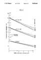
- FIG. 3is a graph showing calculated values indicative of the relationship between differential pressure and gas volume in a fifty foot section of a seventeen and one quarter inch inside diameter (ID) riser;
- FIG. 4is a graph showing calculated values indicative of the relationship between differential pressure and gas volume in a fifty foot section of a nineteen and three quarter inch ID riser;
- FIG. 5is a graph of the response time of the inventive monitoring apparatus for one embodiment
- FIG. 6is a flow diagram of a program executed by the computer controller to calculate an expected differential pressure, then to compare the measured differential pressure with the expected differential pressure, and to issue an alarm if an unfavorable comparison is found;
- FIG. 7ais a computer display showing the monitored relationship of the predicted and measured differential pressures where the two values have overlapped one another.
- FIG. 7bis a computer display showing the monitored relationship of the predicted and measured differential pressures where the onset of a gas kick has been found and an alarm has been given.
- a riser 10extends from the ocean floor to the sea surface and is comprised of many sections fitted together.
- a drill string 12 positioned inside the riser 10serves as a conduit for pumping drilling mud down to a drill bit (not shown) that operates beneath the ocean floor.
- FIG. 1bshows that the drill string 12 is positioned in the center of the riser 10.
- the outside diameter of the drill string 12 and the inside diameter of the riser 10define an area 14, which is referred to as the annulus 14.
- the drill string 12is not perfectly centered, but may reside anywhere within the interior of the riser 10.
- the offshore drilling operationis performed by using a mud pump 16 to pump drilling fluids 17 such as drilling mud down the drill string 12 to flush cuttings from the drill bit.
- drilling fluids 17such as drilling mud down the drill string 12 to flush cuttings from the drill bit.
- the cuttings mixed with the drilling mudcirculate back up the riser 10.
- a blowout preventer 18, controlled from the surfaceis positioned near the ocean floor to prevent uncontrolled fluid flow during periods when the hydrostatic head of the mud is insufficient to control formation pressures.
- the drilling mud 17 from the riser 10passes through a diverter assembly, shown generally as 20, into a mud tank 22 where the cuttings are separated from the drilling mud.
- a pit level sensor 23is used to monitor the level of drilling mud in the mud tank 22.
- the mud pump 16then re-circulates the drilling mud back down the drill string 12 for further use.
- the packers 24can be closed around the drill string 12 to seal off the annular clearance to the rig floor and valves 27 divert violent flow to the overboard diverter 26 which passes it harmlessly overboard on the downwind side of the drilling vessel.
- the dynamics of gas rising in the riser annulus 14are such that by the time ordinary detection means, such as a flow sensor 28, are effective, the gas has risen to the surface and entered the floor before the overboard diverter 26 can be activated.
- FIG. 2shows the inventive monitoring equipment positioned to monitor the absolute pressure and the differential pressure in a riser section 11 at point just above the blowout preventer 18.
- the riser section 11is the lower section of a riser (riser 10 in FIG. 1a) and is typically 50 to 100 feet long.
- the riser section 11is located several hundred or several thousand feet below sea level.
- the absolute pressuregives a measure of the average weight of the mud in the whole riser and can be used as a baseline for calibrating the expected value for the differential pressure.
- the differential pressuregives a measure of the density of the mud or mud/gas mix in the riser section 11 being monitored.
- the monitoring equipmentis connected to the riser section 11 via an upper orifice 42 and a lower orifice 44.
- Diaphragm chambers 46 and 48are positioned at the inlet sides of orifices 42 and 44, respectively.
- a connecting arm 50extending from diaphragm chamber 42, and filled with a fluid of known density, such as fresh water, spans the vertical separation distance ⁇ H between the orifices 42 and 44.
- a suitable vertical separationis fifty feet.
- Connecting arm 52 extending from diaphragm chamber 48is filled with a fluid of known density, and the fluid is preferably water.
- a differential pressure transducer 54is positioned between connecting arms 50 and 52.
- a suitable differential pressure transducer 54may have a dynamic range of ⁇ 30 pounds per square inch (psi) and should be capable of operating at a 5,600 psi ambient pressure. At deeper operating depths, higher ambient pressure transducer ratings must be provided.
- An absolute pressure transducer 56is positioned at an end of connecting arm 52. Similar to the differential pressure transducer 54, the absolute pressure transducer 56 is selected for the dynamic range and operating parameters required by the mud weight and operating depth.
- the differential pressure, ⁇ Pis equal to the pressure exerted at lower orifice 44 minus the sum of the pressure exerted at upper orifice 42 and the column pressure exerted by the column of water in connecting arm 50.
- the absolute pressure, Pis the pressure measured at the lower orifice 44.
- the sensed differential pressure, ⁇ P, and the sensed absolute pressure, Pare sent to an operator at the sea surface using wire communications, fiber optics, or acoustic techniques.
- the differential pressure transducer 54 and absolute pressure transducerare wired to an acoustic telemetry beacon 58 which sends the differential pressure, ⁇ P, and absolute pressure, P, information by pulse position modulation or some other suitable acoustic telemetry technique.
- the cost of electric and fiber optic lines and possible entanglement problems associated with connecting an electric or fiber optic cable directly to the pressure sensors, 54 and 56may be avoided using acoustic techniques; however, in some environments a direct connection may be preferred.
- the average density of drilling mud in riser section 11, ⁇ 11is compared with the average density of drilling mud in the whole riser 10, ⁇ 10 . If mud of uniform density is used for drilling, the ratio will be constant when no gas is entrained in the mud. At the onset of a gas kick, the ratio will change rapidly because the percentage of gas in the riser section 11 will be far greater than the percentage of gas in the whole riser 10. The relative volumes of riser section 11 compared with the whole riser 10 dictate that the same volume of gas will have a greater effect on the riser section 11 than the whole riser 10.
- the average density of the mud or mud/gas mixture in riser section 11, ⁇ 11can be obtained from the differential pressure determined by sensor 54 according to the following equation:
- ⁇ Pis the measured differential pressure obtained from sensor 54;
- ⁇ His the vertical distance between orifice 42 and 44.
- ⁇ wis the density of fluid in connecting arm 50 (presumably water).
- the average density of the mud or mud/gas mixture in the whole riser 10, ⁇ 10can be obtained from the absolute pressure determined by sensor 56 according to the following equation:
- Dis the depth to orifice 44 relative to the surface exit port
- P Eis the absolute exit pressure which is usually atmospheric pressure.
- Comparing the average density of the mud or mud/gas mixture in riser section 11, ⁇ 11 , computed from the differential pressure sensor 54 with the average density of the mud or mud/gas mixture in the whole riser 10, ⁇ 10 , computed from the absolute pressure sensor 56can provide an indication of the onset of a gas kick.
- ⁇ Pis the measured differential pressure
- ⁇ His the vertical separation of orifices 42 and 44;
- V Gis the volume of compressed gas 40 between the two orifices 42 and 44;
- Ais the area dimension of the annulus 14;
- ⁇ mis the density of mud without gas
- ⁇ Gis the density of compressed gas
- ⁇ wis the density of fluid in the connecting arm 50.
- FIGS. 3 and 4calculations based on the above equations have been made which predict the differential pressure, ⁇ P, measurement as a function of the influx of gas in the mud in the riser above the blowout preventer for two different riser diameters.
- the calculationsconsidered the weight of mud being pumped down the drill string and the sensor depth.
- FIG. 3shows the differential pressure measurement which would be found in a 50 foot section of a 17.25 inch diameter riser where the drill pipe has a 6 inch outside diameter. Calculations have been made for drilling mud densities of 18 pounds per gallon (lbs/gallon) and 14 lbs/gallon. In addition, calculations have been made for sea water used as the drilling fluid.
- Drillingis assumed to be conducted with a uniform mud density having a variation of less than ⁇ 0.1 lbs/gallon.
- the gas density, ⁇ Gwas computed based upon compressed gas having an assumed density of 0.09302 lbs/foot 3 at sea level and 0° C. It was assumed that the gas temperature at the blowout preventer was 120° F. and that the riser was open at the surface.
- the flow rate pressure dropwhich is a function of the viscosity of the mud and the flow rate, was not included in the calculations because it was estimated to be less than 1 psi in the measured differential pressure.
- FIG. 4shows the results of the same calculations used for obtaining FIG. 3 except the differential pressure for a 19.75 inch riser was predicted.
- the density of the drilling mud in the lower riser section 11is compared with a predicted value.
- the density in the lower riser sectioncorresponds to the differential pressure detected by sensor 54. If formation gas enters the riser section 11, the density of the mud will be lowered and the measured differential pressure will be different from the expected differential pressure. The discrepancy between the two values is indicative of the onset of a gas kick.
- the amount the differential pressure changes with gas volumeis a function of the depth, volumetric parameters, gas temperature, and mud density.
- the specific volume of gas entering the riser sectioncan be determined from the measured differential pressure and the operating parameters.
- a threshold volume of gas entering the riseris programmed to provide an alarm condition signifying the onset of a gas kick.
- a mud flow dynamics modelfor predicting the expected down hole differential pressure is required when the density of the mud being pumped down the drill string is not uniform or is frequently being changed. For example, if the mud density is reduced at the input to the mud pump, it could take an hour before this mud is circulated through the system where it will be detected at the differential pressure sensor in a deep well. The time delay is easily accounted for from knowing the approximate volumetric parameters of the well and the rate of pumping of the circulated mud. The mud mixing effect can be either modeled or computed from experimental tests.
- FIG. 6shows a computer flow chart which may be used in the practice of this invention.
- the mud pump rpms and measured mud weightare used to calculate the volume of mud and the average mud density pumped down the drill string.
- the expected mud density at the riser section just above the blowout preventeris calculated (note that a properly designed mud flow dynamics model can predict conditions at any point in the circulation).
- the riser section above the blowout preventerincludes the subsea instrumentation comprising the differential pressure sensor and the absolute pressure sensor.
- the expected mud densityis used to calculate the expected differential pressure.
- the expected differential pressureis a function of riser dimensions, mud flow rate, expected mud density, and the vertical separation of the orifices in the riser.
- the measured differential pressureis determined from telemetered data and compared with the expected differential pressure.
- any difference resulting from the comparison of the measured and predicted valuesis compared with a threshold value for gas influx.
- An appreciable amount of gas influxcould be set at one barrel of gas such that quantities of gas entering the riser that are less than one barrel will not trigger an alarm condition.
- the computer display at the surfaceis updated and alarms are given if required. The above described process can be repeated several times each minute and the history of a drilling operation can be stored by the computer. A continuous update is appropriate at each measurement of absolute pressure and differential pressure.
- FIGS. 7a and 7billustrate how the information obtained during a drilling operation using the inventive apparatus may be displayed.
- the predicted differential pressureis shown as a dashed line and the measured differential pressure is shown as a solid line.
- the displaysshow that a change in the density of the drilling mud being pumped down the drill string can be modeled such that the measured and predicted differential pressures continue to track one another.
- an appreciable amount of gashas not entered the riser and; therefore, the measured and predicted values are overlapping for the entire run.
- FIG. 7ban appreciable amount of gas has entered the riser and this is reflected by the measured differential pressure dropping below the expected differential pressure towards the end of the run.
- the displaymay have a section dedicated for alpha-numeric information presentation.
- a visual alarm as well as remedial procedures to be performed by the operator at the surfacemay be given in the alpha-numeric data section. Audible alarms are given to aid in alerting an operator.
Landscapes
- Engineering & Computer Science (AREA)
- Geology (AREA)
- Life Sciences & Earth Sciences (AREA)
- Physics & Mathematics (AREA)
- Mining & Mineral Resources (AREA)
- Environmental & Geological Engineering (AREA)
- Fluid Mechanics (AREA)
- General Life Sciences & Earth Sciences (AREA)
- Geochemistry & Mineralogy (AREA)
- Geophysics (AREA)
- Acoustics & Sound (AREA)
- Remote Sensing (AREA)
- Mechanical Engineering (AREA)
- Earth Drilling (AREA)
Abstract
Description
ΔP=η.sub.11 ΔH-η.sub.w ΔH
P=η.sub.10 D+P.sub.E
ΔP=η.sub.m (ΔH-V.sub.G /A)+η.sub.G V.sub.G /A-η.sub.w ΔH
Claims (17)
Priority Applications (1)
| Application Number | Priority Date | Filing Date | Title |
|---|---|---|---|
| US07/366,093US5006845A (en) | 1989-06-13 | 1989-06-13 | Gas kick detector |
Applications Claiming Priority (1)
| Application Number | Priority Date | Filing Date | Title |
|---|---|---|---|
| US07/366,093US5006845A (en) | 1989-06-13 | 1989-06-13 | Gas kick detector |
Publications (1)
| Publication Number | Publication Date |
|---|---|
| US5006845Atrue US5006845A (en) | 1991-04-09 |
Family
ID=23441642
Family Applications (1)
| Application Number | Title | Priority Date | Filing Date |
|---|---|---|---|
| US07/366,093Expired - LifetimeUS5006845A (en) | 1989-06-13 | 1989-06-13 | Gas kick detector |
Country Status (1)
| Country | Link |
|---|---|
| US (1) | US5006845A (en) |
Cited By (81)
| Publication number | Priority date | Publication date | Assignee | Title |
|---|---|---|---|---|
| US5070949A (en)* | 1987-08-07 | 1991-12-10 | Schlumberger Technology Corporation | Method of analyzing fluid influxes in hydrocarbon wells |
| US5080182A (en)* | 1989-12-20 | 1992-01-14 | Schlumberger Technology Corporation | Method of analyzing and controlling a fluid influx during the drilling of a borehole |
| US5163029A (en)* | 1991-02-08 | 1992-11-10 | Teleco Oilfield Services Inc. | Method for detection of influx gas into a marine riser of an oil or gas rig |
| US5168932A (en)* | 1990-07-25 | 1992-12-08 | Shell Oil Company | Detecting outflow or inflow of fluid in a wellbore |
| FR2682715A1 (en)* | 1991-10-21 | 1993-04-23 | Elf Aquitaine | Gas inrush detector |
| US5303582A (en)* | 1992-10-30 | 1994-04-19 | New Mexico Tech Research Foundation | Pressure-transient testing while drilling |
| US5459697A (en)* | 1994-08-17 | 1995-10-17 | Halliburton Company | MWD surface signal detector having enhanced acoustic detection means |
| US5515336A (en)* | 1994-08-17 | 1996-05-07 | Halliburton Company | MWD surface signal detector having bypass loop acoustic detection means |
| WO1997027381A1 (en)* | 1996-01-24 | 1997-07-31 | Anadrill International S.A. | Determination of fluid influx or efflux |
| WO2000075477A1 (en)* | 1999-06-03 | 2000-12-14 | Exxonmobil Upstream Research Company | Controlling pressure and detecting control problems in gas-lift riser during offshore well drilling |
| FR2798158A1 (en)* | 1999-09-07 | 2001-03-09 | Elf Exploration Prod | Controlling oil production by injecting fluid into well and diverting returning fluid into oil/gas separator whose liquid level and operating pressure are controlled |
| WO2001020120A1 (en)* | 1999-09-17 | 2001-03-22 | Exxonmobil Upstream Research Company | Method and system for storing gas for use in offshore drilling and production operations |
| US6328107B1 (en) | 1999-09-17 | 2001-12-11 | Exxonmobil Upstream Research Company | Method for installing a well casing into a subsea well being drilled with a dual density drilling system |
| US20020178787A1 (en)* | 1997-10-08 | 2002-12-05 | Symyx Technologies, Inc. | Method and apparatus for characterizing materials by using a mechanical resonator |
| US20030000291A1 (en)* | 2001-06-06 | 2003-01-02 | Symyx Technologies, Inc. | Flow detectors having mechanical oscillators, and use thereof in flow characterization systems |
| US20030079912A1 (en)* | 2000-12-18 | 2003-05-01 | Impact Engineering Solutions Limited | Drilling system and method |
| US6560544B1 (en)* | 2000-04-28 | 2003-05-06 | Ford Motor Company | Method for monitoring a mixture |
| US20040099050A1 (en)* | 2002-10-18 | 2004-05-27 | Symyx Technologies, Inc. | Machine fluid sensor and method |
| US20040236512A1 (en)* | 2001-05-15 | 2004-11-25 | Baker Hughes Inc. | Method and apparatus for chemometric estimations of fluid density, viscosity, dielectric constant, and resistivity from mechanical resonator data |
| US20040244487A1 (en)* | 2003-03-21 | 2004-12-09 | Symyx Technologies, Inc. | Mechanical resonator |
| US20040250622A1 (en)* | 2003-03-21 | 2004-12-16 | Symyx Technologies, Inc. | Resonator sensor assembly |
| US20050145019A1 (en)* | 2002-10-18 | 2005-07-07 | Symyx Technologies, Inc. | Environmental control system fluid sensing system and method |
| US20050182566A1 (en)* | 2004-01-14 | 2005-08-18 | Baker Hughes Incorporated | Method and apparatus for determining filtrate contamination from density measurements |
| US6938470B2 (en)* | 2001-05-15 | 2005-09-06 | Baker Hughes Incorporated | Method and apparatus for downhole fluid characterization using flexural mechanical resonators |
| US20050247119A1 (en)* | 2001-05-15 | 2005-11-10 | Baker Hughes Incorporated | Method and apparatus for downhole fluid characterization using flexural mechanical resonators |
| US20060009928A1 (en)* | 2000-06-05 | 2006-01-12 | Aqua Conserve, Inc. | Methods and apparatus for using water use signatures and water pressure in improving water use efficiency |
| US20060016592A1 (en)* | 2004-07-21 | 2006-01-26 | Schlumberger Technology Corporation | Kick warning system using high frequency fluid mode in a borehole |
| US20060115335A1 (en)* | 2004-11-03 | 2006-06-01 | Allen Donald W | Apparatus and method for retroactively installing sensors on marine elements |
| US20060137873A1 (en)* | 2004-12-23 | 2006-06-29 | Derek Caudwell | Apparatus and method for formation evaluation |
| US20060230839A1 (en)* | 2002-08-26 | 2006-10-19 | Morrison Denby G | Apparatuses and methods for monitoring stress in steel catenary risers |
| US20060249288A1 (en)* | 2005-05-04 | 2006-11-09 | Drozd Richard J | Identifying zones of origin of annular gas pressure |
| US20060250893A1 (en)* | 2005-05-06 | 2006-11-09 | Pathfinder Energy Services, Inc. | Drilling fluid pressure pulse detection using a differential transducer |
| US20070052970A1 (en)* | 2003-03-21 | 2007-03-08 | Symyx Technologies, Inc. | Resonator sensor assembly |
| US7194902B1 (en) | 2004-12-23 | 2007-03-27 | Schlumberger Technology Corporation | Apparatus and method for formation evaluation |
| US20070289746A1 (en)* | 2001-09-10 | 2007-12-20 | Ocean Riser Systems As | Arrangement and method for controlling and regulating bottom hole pressure when drilling deepwater offshore wells |
| US20070289740A1 (en)* | 1998-12-21 | 2007-12-20 | Baker Hughes Incorporated | Apparatus and Method for Managing Supply of Additive at Wellsites |
| US20080105434A1 (en)* | 2006-11-07 | 2008-05-08 | Halliburton Energy Services, Inc. | Offshore Universal Riser System |
| US20080115971A1 (en)* | 2004-09-21 | 2008-05-22 | Benthic Geotech Pty Ltd | Remote Gas Monitoring Apparatus for Sealed Drilling |
| EP1936112A3 (en)* | 2001-04-25 | 2008-07-23 | Halliburton Energy Services, Inc. | Method, system and tool for reservoir evaluation and well testing during drilling operations |
| US20080257544A1 (en)* | 2007-04-19 | 2008-10-23 | Baker Hughes Incorporated | System and Method for Crossflow Detection and Intervention in Production Wellbores |
| US20080262737A1 (en)* | 2007-04-19 | 2008-10-23 | Baker Hughes Incorporated | System and Method for Monitoring and Controlling Production from Wells |
| US20080262736A1 (en)* | 2007-04-19 | 2008-10-23 | Baker Hughes Incorporated | System and Method for Monitoring Physical Condition of Production Well Equipment and Controlling Well Production |
| US20080262735A1 (en)* | 2007-04-19 | 2008-10-23 | Baker Hughes Incorporated | System and Method for Water Breakthrough Detection and Intervention in a Production Well |
| US20090114443A1 (en)* | 2007-11-02 | 2009-05-07 | Ability Group Asa | Anchored riserless mud return systems |
| US20090159334A1 (en)* | 2007-12-19 | 2009-06-25 | Bp Corporation North America, Inc. | Method for detecting formation pore pressure by detecting pumps-off gas downhole |
| US7596452B2 (en) | 2007-06-28 | 2009-09-29 | Baker Hughes Incorporated | Compensated caliper using combined acoustic and density measurements |
| US20100067329A1 (en)* | 2008-09-15 | 2010-03-18 | Bp Corporation North America Inc. | Method of determining borehole conditions from distributed measurement data |
| US20110024189A1 (en)* | 2009-07-30 | 2011-02-03 | Halliburton Energy Services, Inc. | Well drilling methods with event detection |
| US20110061872A1 (en)* | 2009-09-10 | 2011-03-17 | Bp Corporation North America Inc. | Systems and methods for circulating out a well bore influx in a dual gradient environment |
| US20110139509A1 (en)* | 2009-12-15 | 2011-06-16 | Halliburton Energy Services, Inc. | Pressure and flow control in drilling operations |
| US20110278014A1 (en)* | 2010-05-12 | 2011-11-17 | William James Hughes | External Jet Pump for Dual Gradient Drilling |
| US20110284209A1 (en)* | 2010-05-20 | 2011-11-24 | Carpenter Robert B | System And Method For Regulating Pressure Within A Well Annulus |
| US20120006613A1 (en)* | 2010-07-06 | 2012-01-12 | Simon Tseytlin | Methods and devices for determination of gas-kick parametrs and prevention of well explosion |
| USRE43199E1 (en)* | 2001-09-10 | 2012-02-21 | Ocean Rider Systems AS | Arrangement and method for regulating bottom hole pressures when drilling deepwater offshore wells |
| US8261826B2 (en) | 2010-04-27 | 2012-09-11 | Halliburton Energy Services, Inc. | Wellbore pressure control with segregated fluid columns |
| US20130140034A1 (en)* | 2011-12-02 | 2013-06-06 | General Electric Company | Seabed well influx control system |
| US20130168100A1 (en)* | 2011-12-28 | 2013-07-04 | Hydril Usa Manufacturing Llc | Apparatuses and Methods for Determining Wellbore Influx Condition Using Qualitative Indications |
| US20130186636A1 (en)* | 2010-05-25 | 2013-07-25 | Agr Subsea, A.S. | Method for circulating a fluid entry out of a subsurface wellbore without shutting in the wellbore |
| US20130327533A1 (en)* | 2012-06-08 | 2013-12-12 | Intelliserv, Llc | Wellbore influx detection in a marine riser |
| US20140047827A1 (en)* | 2012-08-15 | 2014-02-20 | Caterpillar Inc. | Aeration in liquid reservoirs |
| US8820405B2 (en) | 2010-04-27 | 2014-09-02 | Halliburton Energy Services, Inc. | Segregating flowable materials in a well |
| US8833488B2 (en) | 2011-04-08 | 2014-09-16 | Halliburton Energy Services, Inc. | Automatic standpipe pressure control in drilling |
| US20150122505A1 (en)* | 2012-06-07 | 2015-05-07 | General Electric Company | Flow control system |
| US9080407B2 (en) | 2011-05-09 | 2015-07-14 | Halliburton Energy Services, Inc. | Pressure and flow control in drilling operations |
| US20150211362A1 (en)* | 2014-01-30 | 2015-07-30 | Chevron U.S.A. Inc. | Systems and methods for monitoring drilling fluid conditions |
| US20150361742A1 (en)* | 2014-06-12 | 2015-12-17 | Cameron International Corporation | Kick detection systems and methods |
| US9238942B2 (en) | 2006-09-28 | 2016-01-19 | Baker Hughes Incorporated | System and method for stress field based wellbore steering |
| GB2530572A (en)* | 2014-09-29 | 2016-03-30 | Statoil Petroleum As | Estimating cuttings removal |
| US9447647B2 (en) | 2011-11-08 | 2016-09-20 | Halliburton Energy Services, Inc. | Preemptive setpoint pressure offset for flow diversion in drilling operations |
| US9605507B2 (en) | 2011-09-08 | 2017-03-28 | Halliburton Energy Services, Inc. | High temperature drilling with lower temperature rated tools |
| US9631444B1 (en)* | 2016-09-12 | 2017-04-25 | China University Of Petroleum (East China) | Kick information identification apparatus and method assisted for wellbore pressure control during horizontal drilling |
| US20170145763A1 (en)* | 2014-07-15 | 2017-05-25 | Endress + Hauser Messtechnik GmbH + Co. KG | Drilling Rig and Method of Operating It |
| US9759025B2 (en)* | 2014-06-10 | 2017-09-12 | Mhwirth As | Method for detecting wellbore influx |
| EP3311001A4 (en)* | 2015-06-16 | 2019-02-13 | Baker Hughes, A Ge Company, Llc | COMBINED SURCHARGE / PRESSURE LOSS DETECTION IN SURFACE AND DEPTH OF DRILLING |
| CN109488286A (en)* | 2018-12-03 | 2019-03-19 | 西南石油大学 | A kind of oil/gas well underground multipoint pressure overflow monitoring method |
| CN109681136A (en)* | 2018-11-27 | 2019-04-26 | 中国石油集团川庆钻探工程有限公司 | Early overflow monitoring method based on multi-source information fusion |
| CN110185433A (en)* | 2019-05-16 | 2019-08-30 | 中国海洋石油集团有限公司 | A kind of marine riser gas cut monitoring device and method based on Spectral characteristics analysis method |
| US10655455B2 (en)* | 2016-09-20 | 2020-05-19 | Cameron International Corporation | Fluid analysis monitoring system |
| US11053765B2 (en)* | 2017-11-01 | 2021-07-06 | Ensco International Incorporated | Automatic well control |
| US11142971B2 (en) | 2017-06-16 | 2021-10-12 | Landmark Graphics Corporation | Systems and methods for detecting kick and well flow |
| US11215544B2 (en)* | 2016-08-25 | 2022-01-04 | University Of South Florida | Systems and methods for automatically evaluating slurry properties |
Citations (2)
| Publication number | Priority date | Publication date | Assignee | Title |
|---|---|---|---|---|
| US3595075A (en)* | 1969-11-10 | 1971-07-27 | Warren Automatic Tool Co | Method and apparatus for sensing downhole well conditions in a wellbore |
| US4147222A (en)* | 1975-11-28 | 1979-04-03 | Bunker Ramo Corporation | Acoustical underwater communication system for command control and data |
- 1989
- 1989-06-13USUS07/366,093patent/US5006845A/ennot_activeExpired - Lifetime
Patent Citations (2)
| Publication number | Priority date | Publication date | Assignee | Title |
|---|---|---|---|---|
| US3595075A (en)* | 1969-11-10 | 1971-07-27 | Warren Automatic Tool Co | Method and apparatus for sensing downhole well conditions in a wellbore |
| US4147222A (en)* | 1975-11-28 | 1979-04-03 | Bunker Ramo Corporation | Acoustical underwater communication system for command control and data |
Cited By (150)
| Publication number | Priority date | Publication date | Assignee | Title |
|---|---|---|---|---|
| US5070949A (en)* | 1987-08-07 | 1991-12-10 | Schlumberger Technology Corporation | Method of analyzing fluid influxes in hydrocarbon wells |
| US5080182A (en)* | 1989-12-20 | 1992-01-14 | Schlumberger Technology Corporation | Method of analyzing and controlling a fluid influx during the drilling of a borehole |
| US5168932A (en)* | 1990-07-25 | 1992-12-08 | Shell Oil Company | Detecting outflow or inflow of fluid in a wellbore |
| US5163029A (en)* | 1991-02-08 | 1992-11-10 | Teleco Oilfield Services Inc. | Method for detection of influx gas into a marine riser of an oil or gas rig |
| FR2682715A1 (en)* | 1991-10-21 | 1993-04-23 | Elf Aquitaine | Gas inrush detector |
| US5303582A (en)* | 1992-10-30 | 1994-04-19 | New Mexico Tech Research Foundation | Pressure-transient testing while drilling |
| US5459697A (en)* | 1994-08-17 | 1995-10-17 | Halliburton Company | MWD surface signal detector having enhanced acoustic detection means |
| US5515336A (en)* | 1994-08-17 | 1996-05-07 | Halliburton Company | MWD surface signal detector having bypass loop acoustic detection means |
| WO1997027381A1 (en)* | 1996-01-24 | 1997-07-31 | Anadrill International S.A. | Determination of fluid influx or efflux |
| GB2323873A (en)* | 1996-01-24 | 1998-10-07 | Anadrill Int Sa | Determination of fluid influx or efflux |
| GB2323873B (en)* | 1996-01-24 | 2000-02-16 | Anadrill Int Sa | Determination of fluid influx or efflux |
| US7334452B2 (en) | 1997-10-08 | 2008-02-26 | Visyx Technologies, Inc. | Method for characterizing materials by using a mechanical resonator |
| US20020178787A1 (en)* | 1997-10-08 | 2002-12-05 | Symyx Technologies, Inc. | Method and apparatus for characterizing materials by using a mechanical resonator |
| US8682589B2 (en) | 1998-12-21 | 2014-03-25 | Baker Hughes Incorporated | Apparatus and method for managing supply of additive at wellsites |
| US20070289740A1 (en)* | 1998-12-21 | 2007-12-20 | Baker Hughes Incorporated | Apparatus and Method for Managing Supply of Additive at Wellsites |
| WO2000075477A1 (en)* | 1999-06-03 | 2000-12-14 | Exxonmobil Upstream Research Company | Controlling pressure and detecting control problems in gas-lift riser during offshore well drilling |
| US6668943B1 (en) | 1999-06-03 | 2003-12-30 | Exxonmobil Upstream Research Company | Method and apparatus for controlling pressure and detecting well control problems during drilling of an offshore well using a gas-lifted riser |
| FR2798158A1 (en)* | 1999-09-07 | 2001-03-09 | Elf Exploration Prod | Controlling oil production by injecting fluid into well and diverting returning fluid into oil/gas separator whose liquid level and operating pressure are controlled |
| US6578637B1 (en) | 1999-09-17 | 2003-06-17 | Exxonmobil Upstream Research Company | Method and system for storing gas for use in offshore drilling and production operations |
| US6328107B1 (en) | 1999-09-17 | 2001-12-11 | Exxonmobil Upstream Research Company | Method for installing a well casing into a subsea well being drilled with a dual density drilling system |
| WO2001020120A1 (en)* | 1999-09-17 | 2001-03-22 | Exxonmobil Upstream Research Company | Method and system for storing gas for use in offshore drilling and production operations |
| US6560544B1 (en)* | 2000-04-28 | 2003-05-06 | Ford Motor Company | Method for monitoring a mixture |
| US7330796B2 (en)* | 2000-06-05 | 2008-02-12 | Aqua Conserve, Inc. | Methods and apparatus for using water use signatures and water pressure in improving water use efficiency |
| US20060009928A1 (en)* | 2000-06-05 | 2006-01-12 | Aqua Conserve, Inc. | Methods and apparatus for using water use signatures and water pressure in improving water use efficiency |
| US7044237B2 (en)* | 2000-12-18 | 2006-05-16 | Impact Solutions Group Limited | Drilling system and method |
| US7650950B2 (en) | 2000-12-18 | 2010-01-26 | Secure Drilling International, L.P. | Drilling system and method |
| US20030079912A1 (en)* | 2000-12-18 | 2003-05-01 | Impact Engineering Solutions Limited | Drilling system and method |
| US7367411B2 (en) | 2000-12-18 | 2008-05-06 | Secure Drilling International, L.P. | Drilling system and method |
| US20060113110A1 (en)* | 2000-12-18 | 2006-06-01 | Impact Engineering Solutions Limited | Drilling system and method |
| US7278496B2 (en) | 2000-12-18 | 2007-10-09 | Christian Leuchtenberg | Drilling system and method |
| EP1936112A3 (en)* | 2001-04-25 | 2008-07-23 | Halliburton Energy Services, Inc. | Method, system and tool for reservoir evaluation and well testing during drilling operations |
| US7317989B2 (en) | 2001-05-15 | 2008-01-08 | Baker Hughes Incorporated | Method and apparatus for chemometric estimations of fluid density, viscosity, dielectric constant, and resistivity from mechanical resonator data |
| US7162918B2 (en) | 2001-05-15 | 2007-01-16 | Baker Hughes Incorporated | Method and apparatus for downhole fluid characterization using flexural mechanical resonators |
| US20050247119A1 (en)* | 2001-05-15 | 2005-11-10 | Baker Hughes Incorporated | Method and apparatus for downhole fluid characterization using flexural mechanical resonators |
| US6938470B2 (en)* | 2001-05-15 | 2005-09-06 | Baker Hughes Incorporated | Method and apparatus for downhole fluid characterization using flexural mechanical resonators |
| US20040236512A1 (en)* | 2001-05-15 | 2004-11-25 | Baker Hughes Inc. | Method and apparatus for chemometric estimations of fluid density, viscosity, dielectric constant, and resistivity from mechanical resonator data |
| US7302830B2 (en) | 2001-06-06 | 2007-12-04 | Symyx Technologies, Inc. | Flow detectors having mechanical oscillators, and use thereof in flow characterization systems |
| US20030000291A1 (en)* | 2001-06-06 | 2003-01-02 | Symyx Technologies, Inc. | Flow detectors having mechanical oscillators, and use thereof in flow characterization systems |
| US7497266B2 (en)* | 2001-09-10 | 2009-03-03 | Ocean Riser Systems As | Arrangement and method for controlling and regulating bottom hole pressure when drilling deepwater offshore wells |
| US8322439B2 (en)* | 2001-09-10 | 2012-12-04 | Ocean Riser Systems As | Arrangement and method for regulating bottom hole pressures when drilling deepwater offshore wells |
| US20120067590A1 (en)* | 2001-09-10 | 2012-03-22 | Ocean Riser Systems As | Arrangement and method for regulating bottom hole pressures when drilling deepwater offshore wells |
| US20070289746A1 (en)* | 2001-09-10 | 2007-12-20 | Ocean Riser Systems As | Arrangement and method for controlling and regulating bottom hole pressure when drilling deepwater offshore wells |
| USRE43199E1 (en)* | 2001-09-10 | 2012-02-21 | Ocean Rider Systems AS | Arrangement and method for regulating bottom hole pressures when drilling deepwater offshore wells |
| US20060230839A1 (en)* | 2002-08-26 | 2006-10-19 | Morrison Denby G | Apparatuses and methods for monitoring stress in steel catenary risers |
| US7461561B2 (en) | 2002-08-26 | 2008-12-09 | Shell Oil Company | Apparatuses and methods for monitoring stress in steel catenary risers |
| US7194913B2 (en)* | 2002-08-26 | 2007-03-27 | Shell Oil Company | Apparatuses and methods for monitoring stress in steel catenary risers |
| US20060218996A1 (en)* | 2002-10-18 | 2006-10-05 | Symyx Technologies, Inc. | Machine fluid sensor |
| US7350367B2 (en) | 2002-10-18 | 2008-04-01 | Visyx Technologies, Inc. | Environmental control system fluid sensing system and method |
| US20050145019A1 (en)* | 2002-10-18 | 2005-07-07 | Symyx Technologies, Inc. | Environmental control system fluid sensing system and method |
| US7254990B2 (en) | 2002-10-18 | 2007-08-14 | Visyx Technologies, Inc. | Machine fluid sensor |
| US20040099050A1 (en)* | 2002-10-18 | 2004-05-27 | Symyx Technologies, Inc. | Machine fluid sensor and method |
| US7043969B2 (en) | 2002-10-18 | 2006-05-16 | Symyx Technologies, Inc. | Machine fluid sensor and method |
| US20040244487A1 (en)* | 2003-03-21 | 2004-12-09 | Symyx Technologies, Inc. | Mechanical resonator |
| US20040250622A1 (en)* | 2003-03-21 | 2004-12-16 | Symyx Technologies, Inc. | Resonator sensor assembly |
| US7721590B2 (en) | 2003-03-21 | 2010-05-25 | MEAS France | Resonator sensor assembly |
| US20070052970A1 (en)* | 2003-03-21 | 2007-03-08 | Symyx Technologies, Inc. | Resonator sensor assembly |
| US7210332B2 (en) | 2003-03-21 | 2007-05-01 | Symyx Technologies, Inc. | Mechanical resonator |
| US20100218353A1 (en)* | 2003-03-21 | 2010-09-02 | MEAS France | Resonator sensor assembly |
| US8732938B2 (en) | 2003-03-21 | 2014-05-27 | MEAS France | Method of packaging a sensor |
| US20050182566A1 (en)* | 2004-01-14 | 2005-08-18 | Baker Hughes Incorporated | Method and apparatus for determining filtrate contamination from density measurements |
| WO2005091204A1 (en) | 2004-03-16 | 2005-09-29 | Baker Hughes Incorporated | Method and apparatus for chemometric estimations of fluid density, viscosity, dielectric constant, and resistivity from mechanical resonator data |
| US7334651B2 (en) | 2004-07-21 | 2008-02-26 | Schlumberger Technology Corporation | Kick warning system using high frequency fluid mode in a borehole |
| US20060016592A1 (en)* | 2004-07-21 | 2006-01-26 | Schlumberger Technology Corporation | Kick warning system using high frequency fluid mode in a borehole |
| US9080406B2 (en) | 2004-09-21 | 2015-07-14 | Benthic Geotech Pty Ltd | Remote gas monitoring apparatus for seabed drilling |
| US20080115971A1 (en)* | 2004-09-21 | 2008-05-22 | Benthic Geotech Pty Ltd | Remote Gas Monitoring Apparatus for Sealed Drilling |
| EP1792048A4 (en)* | 2004-09-21 | 2013-06-12 | Benthic Geotech Pty Ltd | Remote gas monitoring apparatus for seabed drilling |
| US20060115335A1 (en)* | 2004-11-03 | 2006-06-01 | Allen Donald W | Apparatus and method for retroactively installing sensors on marine elements |
| US7398697B2 (en) | 2004-11-03 | 2008-07-15 | Shell Oil Company | Apparatus and method for retroactively installing sensors on marine elements |
| US20060137873A1 (en)* | 2004-12-23 | 2006-06-29 | Derek Caudwell | Apparatus and method for formation evaluation |
| US7194902B1 (en) | 2004-12-23 | 2007-03-27 | Schlumberger Technology Corporation | Apparatus and method for formation evaluation |
| US7222671B2 (en) | 2004-12-23 | 2007-05-29 | Schlumberger Technology Corporation | Apparatus and method for formation evaluation |
| US7438128B2 (en) | 2005-05-04 | 2008-10-21 | Halliburton Energy Services, Inc. | Identifying zones of origin of annular gas pressure |
| US20060249288A1 (en)* | 2005-05-04 | 2006-11-09 | Drozd Richard J | Identifying zones of origin of annular gas pressure |
| US7489591B2 (en)* | 2005-05-06 | 2009-02-10 | Pathfinder Energy Services, Inc. | Drilling fluid pressure pulse detection using a differential transducer |
| US20060250893A1 (en)* | 2005-05-06 | 2006-11-09 | Pathfinder Energy Services, Inc. | Drilling fluid pressure pulse detection using a differential transducer |
| US9238942B2 (en) | 2006-09-28 | 2016-01-19 | Baker Hughes Incorporated | System and method for stress field based wellbore steering |
| US20100018715A1 (en)* | 2006-11-07 | 2010-01-28 | Halliburton Energy Services, Inc. | Offshore universal riser system |
| US9157285B2 (en) | 2006-11-07 | 2015-10-13 | Halliburton Energy Services, Inc. | Offshore drilling method |
| US8776894B2 (en) | 2006-11-07 | 2014-07-15 | Halliburton Energy Services, Inc. | Offshore universal riser system |
| US8881831B2 (en) | 2006-11-07 | 2014-11-11 | Halliburton Energy Services, Inc. | Offshore universal riser system |
| US8887814B2 (en) | 2006-11-07 | 2014-11-18 | Halliburton Energy Services, Inc. | Offshore universal riser system |
| US9051790B2 (en) | 2006-11-07 | 2015-06-09 | Halliburton Energy Services, Inc. | Offshore drilling method |
| US9085940B2 (en) | 2006-11-07 | 2015-07-21 | Halliburton Energy Services, Inc. | Offshore universal riser system |
| US9127511B2 (en) | 2006-11-07 | 2015-09-08 | Halliburton Energy Services, Inc. | Offshore universal riser system |
| US9127512B2 (en) | 2006-11-07 | 2015-09-08 | Halliburton Energy Services, Inc. | Offshore drilling method |
| US8033335B2 (en)* | 2006-11-07 | 2011-10-11 | Halliburton Energy Services, Inc. | Offshore universal riser system |
| US9376870B2 (en) | 2006-11-07 | 2016-06-28 | Halliburton Energy Services, Inc. | Offshore universal riser system |
| US20080105434A1 (en)* | 2006-11-07 | 2008-05-08 | Halliburton Energy Services, Inc. | Offshore Universal Riser System |
| US20080257544A1 (en)* | 2007-04-19 | 2008-10-23 | Baker Hughes Incorporated | System and Method for Crossflow Detection and Intervention in Production Wellbores |
| US7805248B2 (en) | 2007-04-19 | 2010-09-28 | Baker Hughes Incorporated | System and method for water breakthrough detection and intervention in a production well |
| US20080262737A1 (en)* | 2007-04-19 | 2008-10-23 | Baker Hughes Incorporated | System and Method for Monitoring and Controlling Production from Wells |
| US7711486B2 (en) | 2007-04-19 | 2010-05-04 | Baker Hughes Incorporated | System and method for monitoring physical condition of production well equipment and controlling well production |
| US20080262736A1 (en)* | 2007-04-19 | 2008-10-23 | Baker Hughes Incorporated | System and Method for Monitoring Physical Condition of Production Well Equipment and Controlling Well Production |
| US20080262735A1 (en)* | 2007-04-19 | 2008-10-23 | Baker Hughes Incorporated | System and Method for Water Breakthrough Detection and Intervention in a Production Well |
| US7596452B2 (en) | 2007-06-28 | 2009-09-29 | Baker Hughes Incorporated | Compensated caliper using combined acoustic and density measurements |
| US20090114443A1 (en)* | 2007-11-02 | 2009-05-07 | Ability Group Asa | Anchored riserless mud return systems |
| US7938190B2 (en)* | 2007-11-02 | 2011-05-10 | Agr Subsea, Inc. | Anchored riserless mud return systems |
| US20090159334A1 (en)* | 2007-12-19 | 2009-06-25 | Bp Corporation North America, Inc. | Method for detecting formation pore pressure by detecting pumps-off gas downhole |
| US9228401B2 (en)* | 2008-09-15 | 2016-01-05 | Bp Corporation North America Inc. | Method of determining borehole conditions from distributed measurement data |
| US20100067329A1 (en)* | 2008-09-15 | 2010-03-18 | Bp Corporation North America Inc. | Method of determining borehole conditions from distributed measurement data |
| US8281875B2 (en) | 2008-12-19 | 2012-10-09 | Halliburton Energy Services, Inc. | Pressure and flow control in drilling operations |
| US20110139506A1 (en)* | 2008-12-19 | 2011-06-16 | Halliburton Energy Services, Inc. | Pressure and flow control in drilling operations |
| US20110024189A1 (en)* | 2009-07-30 | 2011-02-03 | Halliburton Energy Services, Inc. | Well drilling methods with event detection |
| US9567843B2 (en) | 2009-07-30 | 2017-02-14 | Halliburton Energy Services, Inc. | Well drilling methods with event detection |
| US8517111B2 (en)* | 2009-09-10 | 2013-08-27 | Bp Corporation North America Inc. | Systems and methods for circulating out a well bore influx in a dual gradient environment |
| US20110061872A1 (en)* | 2009-09-10 | 2011-03-17 | Bp Corporation North America Inc. | Systems and methods for circulating out a well bore influx in a dual gradient environment |
| US8286730B2 (en) | 2009-12-15 | 2012-10-16 | Halliburton Energy Services, Inc. | Pressure and flow control in drilling operations |
| US20110139509A1 (en)* | 2009-12-15 | 2011-06-16 | Halliburton Energy Services, Inc. | Pressure and flow control in drilling operations |
| US8261826B2 (en) | 2010-04-27 | 2012-09-11 | Halliburton Energy Services, Inc. | Wellbore pressure control with segregated fluid columns |
| US8820405B2 (en) | 2010-04-27 | 2014-09-02 | Halliburton Energy Services, Inc. | Segregating flowable materials in a well |
| US20110278014A1 (en)* | 2010-05-12 | 2011-11-17 | William James Hughes | External Jet Pump for Dual Gradient Drilling |
| US8403059B2 (en)* | 2010-05-12 | 2013-03-26 | Sunstone Technologies, Llc | External jet pump for dual gradient drilling |
| US20110284209A1 (en)* | 2010-05-20 | 2011-11-24 | Carpenter Robert B | System And Method For Regulating Pressure Within A Well Annulus |
| US8353351B2 (en)* | 2010-05-20 | 2013-01-15 | Chevron U.S.A. Inc. | System and method for regulating pressure within a well annulus |
| US20130186636A1 (en)* | 2010-05-25 | 2013-07-25 | Agr Subsea, A.S. | Method for circulating a fluid entry out of a subsurface wellbore without shutting in the wellbore |
| US8851181B2 (en)* | 2010-05-25 | 2014-10-07 | Agr Subsea, A.S. | Method for circulating a fluid entry out of a subsurface wellbore without shutting in the wellbore |
| US20120006613A1 (en)* | 2010-07-06 | 2012-01-12 | Simon Tseytlin | Methods and devices for determination of gas-kick parametrs and prevention of well explosion |
| US8235143B2 (en)* | 2010-07-06 | 2012-08-07 | Simon Tseytlin | Methods and devices for determination of gas-kick parametrs and prevention of well explosion |
| US8833488B2 (en) | 2011-04-08 | 2014-09-16 | Halliburton Energy Services, Inc. | Automatic standpipe pressure control in drilling |
| US9080407B2 (en) | 2011-05-09 | 2015-07-14 | Halliburton Energy Services, Inc. | Pressure and flow control in drilling operations |
| US9605507B2 (en) | 2011-09-08 | 2017-03-28 | Halliburton Energy Services, Inc. | High temperature drilling with lower temperature rated tools |
| US9447647B2 (en) | 2011-11-08 | 2016-09-20 | Halliburton Energy Services, Inc. | Preemptive setpoint pressure offset for flow diversion in drilling operations |
| US20130140034A1 (en)* | 2011-12-02 | 2013-06-06 | General Electric Company | Seabed well influx control system |
| US9080427B2 (en)* | 2011-12-02 | 2015-07-14 | General Electric Company | Seabed well influx control system |
| US9033048B2 (en)* | 2011-12-28 | 2015-05-19 | Hydril Usa Manufacturing Llc | Apparatuses and methods for determining wellbore influx condition using qualitative indications |
| US20130168100A1 (en)* | 2011-12-28 | 2013-07-04 | Hydril Usa Manufacturing Llc | Apparatuses and Methods for Determining Wellbore Influx Condition Using Qualitative Indications |
| US10233708B2 (en) | 2012-04-10 | 2019-03-19 | Halliburton Energy Services, Inc. | Pressure and flow control in drilling operations |
| US9476271B2 (en)* | 2012-06-07 | 2016-10-25 | General Electric Company | Flow control system |
| US20150122505A1 (en)* | 2012-06-07 | 2015-05-07 | General Electric Company | Flow control system |
| US20130327533A1 (en)* | 2012-06-08 | 2013-12-12 | Intelliserv, Llc | Wellbore influx detection in a marine riser |
| WO2013184676A1 (en)* | 2012-06-08 | 2013-12-12 | Intelliserv, Llc | Wellbore influx detection in a marine riser |
| US20140047827A1 (en)* | 2012-08-15 | 2014-02-20 | Caterpillar Inc. | Aeration in liquid reservoirs |
| US20150211362A1 (en)* | 2014-01-30 | 2015-07-30 | Chevron U.S.A. Inc. | Systems and methods for monitoring drilling fluid conditions |
| US9759025B2 (en)* | 2014-06-10 | 2017-09-12 | Mhwirth As | Method for detecting wellbore influx |
| US20150361742A1 (en)* | 2014-06-12 | 2015-12-17 | Cameron International Corporation | Kick detection systems and methods |
| US10151159B2 (en)* | 2014-06-12 | 2018-12-11 | Cameron International Corporation | Kick detection systems and methods |
| US20170145763A1 (en)* | 2014-07-15 | 2017-05-25 | Endress + Hauser Messtechnik GmbH + Co. KG | Drilling Rig and Method of Operating It |
| GB2530572B (en)* | 2014-09-29 | 2021-03-10 | Equinor Energy As | Estimating cuttings removal |
| GB2530572A (en)* | 2014-09-29 | 2016-03-30 | Statoil Petroleum As | Estimating cuttings removal |
| US10060209B2 (en) | 2014-09-29 | 2018-08-28 | Statoil Petroleum As | Estimating cuttings removal |
| EP3311001A4 (en)* | 2015-06-16 | 2019-02-13 | Baker Hughes, A Ge Company, Llc | COMBINED SURCHARGE / PRESSURE LOSS DETECTION IN SURFACE AND DEPTH OF DRILLING |
| US11215544B2 (en)* | 2016-08-25 | 2022-01-04 | University Of South Florida | Systems and methods for automatically evaluating slurry properties |
| US9631444B1 (en)* | 2016-09-12 | 2017-04-25 | China University Of Petroleum (East China) | Kick information identification apparatus and method assisted for wellbore pressure control during horizontal drilling |
| US10655455B2 (en)* | 2016-09-20 | 2020-05-19 | Cameron International Corporation | Fluid analysis monitoring system |
| US11142971B2 (en) | 2017-06-16 | 2021-10-12 | Landmark Graphics Corporation | Systems and methods for detecting kick and well flow |
| US11053765B2 (en)* | 2017-11-01 | 2021-07-06 | Ensco International Incorporated | Automatic well control |
| CN109681136A (en)* | 2018-11-27 | 2019-04-26 | 中国石油集团川庆钻探工程有限公司 | Early overflow monitoring method based on multi-source information fusion |
| CN109488286A (en)* | 2018-12-03 | 2019-03-19 | 西南石油大学 | A kind of oil/gas well underground multipoint pressure overflow monitoring method |
| CN109488286B (en)* | 2018-12-03 | 2022-03-11 | 西南石油大学 | A multi-point pressure measurement overflow monitoring method in oil and gas wells |
| CN110185433A (en)* | 2019-05-16 | 2019-08-30 | 中国海洋石油集团有限公司 | A kind of marine riser gas cut monitoring device and method based on Spectral characteristics analysis method |
Similar Documents
| Publication | Publication Date | Title |
|---|---|---|
| US5006845A (en) | Gas kick detector | |
| US3955411A (en) | Method for measuring the vertical height and/or density of drilling fluid columns | |
| US6234250B1 (en) | Real time wellbore pit volume monitoring system and method | |
| US8689904B2 (en) | Detection of gas influx into a wellbore | |
| CA2523039C (en) | Subsurface measurement apparatus, system, and process for improved well drilling, control, and production | |
| US4867254A (en) | Method of controlling fluid influxes in hydrocarbon wells | |
| CA1057081A (en) | Method and apparatus for determining on-board a heaving vessel the flow rate of drilling fluid flowing out of a wellhole and into a telescoping marine riser connected between the wellhole and vessel | |
| US9759025B2 (en) | Method for detecting wellbore influx | |
| US3910110A (en) | Motion compensated blowout and loss circulation detection | |
| EP0302558B1 (en) | Method of analysing fluid influxes in hydrocarbon wells | |
| US5063776A (en) | Method and system for measurement of fluid flow in a drilling rig return line | |
| US4282939A (en) | Method and apparatus for compensating well control instrumentation for the effects of vessel heave | |
| US4733233A (en) | Method and apparatus for borehole fluid influx detection | |
| US4754641A (en) | Method and apparatus for measurement of fluid flow in a drilling rig return line | |
| US5163029A (en) | Method for detection of influx gas into a marine riser of an oil or gas rig | |
| EP2610427B1 (en) | Apparatuses and methods for determining wellbore influx condition using qualitative indications | |
| US7950472B2 (en) | Downhole local mud weight measurement near bit | |
| EP1936112B1 (en) | Method, system and tool for reservoir evaluation and well testing during drilling operations | |
| US8794350B2 (en) | Method for detecting formation pore pressure by detecting pumps-off gas downhole | |
| US4495805A (en) | In-situ permeability determining method | |
| US3827295A (en) | Bell nipple monitor | |
| Aldred et al. | Using downhole annular pressure measurements to improve drilling performance | |
| US4840061A (en) | Method of detecting a fluid influx which could lead to a blow-out during the drilling of a borehole | |
| US3809170A (en) | Method and apparatus for detecting fluid influx in offshore drilling operations | |
| Schubert et al. | Early kick detection through liquid level monitoring in the wellbore |
Legal Events
| Date | Code | Title | Description |
|---|---|---|---|
| AS | Assignment | Owner name:HONEYWELL INC., HONEYWELL PLAZA, MINNEAPOLIS, MN 5 Free format text:ASSIGNMENT OF ASSIGNORS INTEREST.;ASSIGNORS:CALCAR, HENRY V.;MARSH, GARY L.;REEL/FRAME:005097/0749;SIGNING DATES FROM 19890524 TO 19890605 | |
| FEPP | Fee payment procedure | Free format text:PAYOR NUMBER ASSIGNED (ORIGINAL EVENT CODE: ASPN); ENTITY STATUS OF PATENT OWNER: LARGE ENTITY | |
| STCF | Information on status: patent grant | Free format text:PATENTED CASE | |
| AS | Assignment | Owner name:ALLIANT TECHSYSTEMS INC., MINNESOTA Free format text:ASSIGNMENT OF ASSIGNORS INTEREST.;ASSIGNOR:HONEYWELL INC., A CORP. OF DE;REEL/FRAME:005984/0131 Effective date:19911127 | |
| CC | Certificate of correction | ||
| FEPP | Fee payment procedure | Free format text:PAYOR NUMBER ASSIGNED (ORIGINAL EVENT CODE: ASPN); ENTITY STATUS OF PATENT OWNER: LARGE ENTITY Free format text:PAYER NUMBER DE-ASSIGNED (ORIGINAL EVENT CODE: RMPN); ENTITY STATUS OF PATENT OWNER: LARGE ENTITY | |
| FPAY | Fee payment | Year of fee payment:4 | |
| REFU | Refund | Free format text:REFUND OF EXCESS PAYMENTS PROCESSED (ORIGINAL EVENT CODE: R169); ENTITY STATUS OF PATENT OWNER: LARGE ENTITY | |
| FEPP | Fee payment procedure | Free format text:PAYER NUMBER DE-ASSIGNED (ORIGINAL EVENT CODE: RMPN); ENTITY STATUS OF PATENT OWNER: LARGE ENTITY Free format text:PAYOR NUMBER ASSIGNED (ORIGINAL EVENT CODE: ASPN); ENTITY STATUS OF PATENT OWNER: LARGE ENTITY | |
| AS | Assignment | Owner name:HUGHES AIRCRAFT COMPANY, CALIFORNIA Free format text:ASSIGNMENT OF ASSIGNORS INTEREST;ASSIGNOR:ALLIANT TECHSYSTEMS, INC.;REEL/FRAME:008848/0210 Effective date:19971126 | |
| FPAY | Fee payment | Year of fee payment:8 | |
| FEPP | Fee payment procedure | Free format text:PAYER NUMBER DE-ASSIGNED (ORIGINAL EVENT CODE: RMPN); ENTITY STATUS OF PATENT OWNER: LARGE ENTITY Free format text:PAYOR NUMBER ASSIGNED (ORIGINAL EVENT CODE: ASPN); ENTITY STATUS OF PATENT OWNER: LARGE ENTITY | |
| FPAY | Fee payment | Year of fee payment:12 | |
| SULP | Surcharge for late payment | Year of fee payment:11 | |
| REMI | Maintenance fee reminder mailed | ||
| AS | Assignment | Owner name:HE HOLDINGS, INC., A DELAWARE CORP., CALIFORNIA Free format text:CHANGE OF NAME;ASSIGNOR:HUGHES AIRCRAFT COMPANY, A CORPORATION OF THE STATE OF DELAWARE;REEL/FRAME:016087/0541 Effective date:19971217 Owner name:RAYTHEON COMPANY, MASSACHUSETTS Free format text:MERGER;ASSIGNOR:HE HOLDINGS, INC. DBA HUGHES ELECTRONICS;REEL/FRAME:016116/0506 Effective date:19971217 |