US5006749A - Method and apparatus for using ultrasonic energy for moving microminiature elements - Google Patents
Method and apparatus for using ultrasonic energy for moving microminiature elementsDownload PDFInfo
- Publication number
- US5006749A US5006749AUS07/416,532US41653289AUS5006749AUS 5006749 AUS5006749 AUS 5006749AUS 41653289 AUS41653289 AUS 41653289AUS 5006749 AUS5006749 AUS 5006749A
- Authority
- US
- United States
- Prior art keywords
- membrane
- micro
- layer
- ultrasonic
- miniature
- Prior art date
- Legal status (The legal status is an assumption and is not a legal conclusion. Google has not performed a legal analysis and makes no representation as to the accuracy of the status listed.)
- Expired - Lifetime
Links
Images


Classifications
- H—ELECTRICITY
- H02—GENERATION; CONVERSION OR DISTRIBUTION OF ELECTRIC POWER
- H02N—ELECTRIC MACHINES NOT OTHERWISE PROVIDED FOR
- H02N2/00—Electric machines in general using piezoelectric effect, electrostriction or magnetostriction
- H02N2/02—Electric machines in general using piezoelectric effect, electrostriction or magnetostriction producing linear motion, e.g. actuators; Linear positioners ; Linear motors
- H02N2/028—Electric machines in general using piezoelectric effect, electrostriction or magnetostriction producing linear motion, e.g. actuators; Linear positioners ; Linear motors along multiple or arbitrary translation directions, e.g. XYZ stages
- B—PERFORMING OPERATIONS; TRANSPORTING
- B01—PHYSICAL OR CHEMICAL PROCESSES OR APPARATUS IN GENERAL
- B01L—CHEMICAL OR PHYSICAL LABORATORY APPARATUS FOR GENERAL USE
- B01L3/00—Containers or dishes for laboratory use, e.g. laboratory glassware; Droppers
- B01L3/50—Containers for the purpose of retaining a material to be analysed, e.g. test tubes
- B01L3/502—Containers for the purpose of retaining a material to be analysed, e.g. test tubes with fluid transport, e.g. in multi-compartment structures
- B01L3/5027—Containers for the purpose of retaining a material to be analysed, e.g. test tubes with fluid transport, e.g. in multi-compartment structures by integrated microfluidic structures, i.e. dimensions of channels and chambers are such that surface tension forces are important, e.g. lab-on-a-chip
- B01L3/502769—Containers for the purpose of retaining a material to be analysed, e.g. test tubes with fluid transport, e.g. in multi-compartment structures by integrated microfluidic structures, i.e. dimensions of channels and chambers are such that surface tension forces are important, e.g. lab-on-a-chip characterised by multiphase flow arrangements
- B01L3/502784—Containers for the purpose of retaining a material to be analysed, e.g. test tubes with fluid transport, e.g. in multi-compartment structures by integrated microfluidic structures, i.e. dimensions of channels and chambers are such that surface tension forces are important, e.g. lab-on-a-chip characterised by multiphase flow arrangements specially adapted for droplet or plug flow, e.g. digital microfluidics
- B01L3/502792—Containers for the purpose of retaining a material to be analysed, e.g. test tubes with fluid transport, e.g. in multi-compartment structures by integrated microfluidic structures, i.e. dimensions of channels and chambers are such that surface tension forces are important, e.g. lab-on-a-chip characterised by multiphase flow arrangements specially adapted for droplet or plug flow, e.g. digital microfluidics for moving individual droplets on a plate, e.g. by locally altering surface tension
- H—ELECTRICITY
- H02—GENERATION; CONVERSION OR DISTRIBUTION OF ELECTRIC POWER
- H02N—ELECTRIC MACHINES NOT OTHERWISE PROVIDED FOR
- H02N2/00—Electric machines in general using piezoelectric effect, electrostriction or magnetostriction
- H02N2/02—Electric machines in general using piezoelectric effect, electrostriction or magnetostriction producing linear motion, e.g. actuators; Linear positioners ; Linear motors
- H02N2/08—Electric machines in general using piezoelectric effect, electrostriction or magnetostriction producing linear motion, e.g. actuators; Linear positioners ; Linear motors using travelling waves, i.e. Rayleigh surface waves
- H—ELECTRICITY
- H02—GENERATION; CONVERSION OR DISTRIBUTION OF ELECTRIC POWER
- H02N—ELECTRIC MACHINES NOT OTHERWISE PROVIDED FOR
- H02N2/00—Electric machines in general using piezoelectric effect, electrostriction or magnetostriction
- H02N2/10—Electric machines in general using piezoelectric effect, electrostriction or magnetostriction producing rotary motion, e.g. rotary motors
- H02N2/16—Electric machines in general using piezoelectric effect, electrostriction or magnetostriction producing rotary motion, e.g. rotary motors using travelling waves, i.e. Rayleigh surface waves
- B—PERFORMING OPERATIONS; TRANSPORTING
- B01—PHYSICAL OR CHEMICAL PROCESSES OR APPARATUS IN GENERAL
- B01L—CHEMICAL OR PHYSICAL LABORATORY APPARATUS FOR GENERAL USE
- B01L2400/00—Moving or stopping fluids
- B01L2400/04—Moving fluids with specific forces or mechanical means
- B01L2400/0403—Moving fluids with specific forces or mechanical means specific forces
- B01L2400/0433—Moving fluids with specific forces or mechanical means specific forces vibrational forces
- B01L2400/0439—Moving fluids with specific forces or mechanical means specific forces vibrational forces ultrasonic vibrations, vibrating piezo elements
- B—PERFORMING OPERATIONS; TRANSPORTING
- B01—PHYSICAL OR CHEMICAL PROCESSES OR APPARATUS IN GENERAL
- B01L—CHEMICAL OR PHYSICAL LABORATORY APPARATUS FOR GENERAL USE
- B01L2400/00—Moving or stopping fluids
- B01L2400/04—Moving fluids with specific forces or mechanical means
- B01L2400/0493—Specific techniques used
- B01L2400/0496—Travelling waves, e.g. in combination with electrical or acoustic forces
Definitions
- This inventionrelates to micromotor devices for moving miniature mechanical parts using ultrasonic waves and also for using ultrasonic vibrations to reduce friction between such parts and their supporting structures.
- micro-miniature structuressuch as micro gears, pin joints and sliders, all of which may be movable components forming part of or used in combination with a particular micro-mechanical device.
- the structures disclosedare formed in a batch process using integrated circuit type semiconductor fabrication techniques that include deposition and etching steps to form movable elements. Once such micro-miniature structural components have been formed, it then becomes necessary to provide a precisely controllable force or motor to move the elements in the desired manner including timing, speed and direction.
- One approach to the problem of moving micro-miniature elementsis to utilize electrostatic force means to form micro motors.
- Electrostatic force meansto form micro motors.
- electrodes for the micromotor rotor and stator poles and also circuit paths and terminals for the required powermust be provided. This tends to complicate the construction of micro-miniature devices for some applications.
- a general object of the present inventionis to provide a system for moving micro-miniature elements utilizing ultrasonic energy instead of electrostatic force.
- Another object of the inventionis to provide a method using ultrasonic wave energy for moving or driving micro-miniature structural elements in predescribed paths, for predetermined distances and at preselected speeds.
- Still another objectis to provide drive means in which electrical potentials are isolated from the region in which motion occurs, for example, as required for certain medical applications of microscopic movable components.
- Another objectis to provide a mechanical drive or friction reduction of a movable element that produces minimal electrical interference to nearby circuits.
- Another objectis to provide means for moving quantities of small objects such as solid powdered chemicals and possibly liquid droplets or streams in a controlled fashion.
- Yet another objectis to provide drive means that will function properly while in a liquid environment even though the liquid might be electrically conducting.
- a wellis provided on one side of a substrate structure that includes a planar membrane on which ultrasonic plate waves can be generated and propagated.
- the membraneis surrounded by the well and is comprised of a horizontal upper or top layer of silicon nitride and an adjacent under-layer of piezoelectric zinc oxide. Spaced apart on the underlayer are a pair of transducing drive electrodes which are in the recessed well region below the membrane, thereby providing a featureless smooth surface on the upper side of the silicon nitride layer on which a movable element is supported and can be driven.
- the wellmay be formed in the upper side of the substrate surrounding the movable element.
- the transducer electrodesare each connected to a source of alternating electrical voltage.
- a voltageis supplied to either transducer, a particle motion is generated which produces a flexural wave action in the composite membrane.
- the particle motionis retrograde elliptical, meaning that for a wave traveling to the right, the particles of the membrane at its point of contact with the driven object will move to the left.
- the pattern of deformation of the membrane for a wave travelling to the righttravels to the right along with the wave.
- the driven microscopic elementwill move if the wave amplitude can be made large enough and the movable element can be suitably coupled to the plate or membrane.
- the required flexural wave actionis produced without a piezoelectric layer by electrostriction wherein elastic deformation of a dielectric is induced by an electric field.
- the electric fieldis created within a dielectric layer such as silicon nitride situated between a conductive ground plane and a transducer electrode having two or more conductors that are spaced one wave length apart. Voltage applied to the transducers causes a membrane wave action and thus movement of an object on the ground layer over the membrane in a manner similar to that of a piezoelectric type embodiment.
- the ultrasonic waves in the membrane platemay be generated by applying a D.C. bias voltage to cause electron or hole drift in a semiconductor located on the same membrane to form an ultrasonic oscillator.
- a D.C. bias voltageto cause electron or hole drift in a semiconductor located on the same membrane to form an ultrasonic oscillator.
- the low speed of the wavewill permit a relatively small D.C. drift electric field to be used.
- the ultrasonic wave action produced in accordance with the inventionmay be provided in various micro-miniature structures to produce various motions in different directions, in either linear or circular paths, for one or more movable elements on a membrane plate. Such wave action can also be used to provide a dithering action for reducing the friction of moving micromotor or microscopic elements.
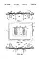
- FIG. 1is a partially diagrammatic view in elevation and in section of an ultrasonic micromotor for moving an object in one direction according to the present invention.
- FIG. 1Ais a bottom side plan view of the micromotor shown in FIG. 1.
- FIG. 1Bis a partially diagrammatic view in elevation and in section showing a modified form of the ultrasonic micromotor of FIG. 1.
- FIG. 2Ais a partially diagrammatic view in elevation and in section showing yet another modified form of ultrasonic micromotor using patterned ground plane areas according to the invention.
- FIG. 2Bis a partially diagrammatic view in elevation and in section showing another micromotor embodiment utilizing buried transducers.
- FIG. 3is a partially diagrammatic view in elevation and in section showing an ultrasonic micromotor similar to the one in FIG. 1, but having an external amplifier.
- FIG. 4is a partially diagrammatic view in elevation and in section showing an ultrasonic micromotor employing acoustic amplification in the composite membrane in accordance with the invention.
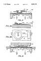
- FIG. 5is a view in elevation and in section showing a micromotor according to the invention as it appears in combination with a micromechanical pin joint for providing a dithering action.
- FIG. 5Ais a view in elevation and in section showing a micromotor according to the invention using a simple transducer to vibrate (dither) a pivotal micromechanical member to reduce friction.
- FIG. 5Bis a plan view of the micromotor dithering arrangement of FIG. 5A.
- FIG. 6is a view in elevation and in section showing a micromotor according to the present invention in combination with a movable slider held loosely in ways.
- FIG. 7is a view in elevation and in section showing a micromotor according to the present invention having electrical means for clamping a movable object to the surface of a supporting membrane.
- FIGS. 8A-8Dare a series of diagrammatic views showing various ways in which an object can be moved utilizing a micromotor embodying principles of the invention.
- FIG. 8Eis a diagrammatic plan view of an ultrasonic micromotor according to the invention utilizing a circular membrane of variable thickness.
- FIG. 8Fis a view in section taken along line 8F--8F of FIG. 8E.
- FIG. 9is a diagrammatic plan view of another way in which radial motion of movable objects may be produced by a micromotor according to the invention.
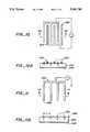
- FIG. 10is a plan view of a transducer for a piezoelectric micromotor according to the invention.
- FIG. 10Ais a view in section taken at line 10A--10A of FIG. 10 and showing diagrammatically how wave action in a membrane is produced.
- FIG. 11is a plan view of a transducer for an electrostriction micromotor embodiment according to the invention.
- FIG. 11Ais a view in section taken along line 11A-11A of FIG. 11 showing diagrammatically how wave action is produced in a non-piezoelectric membrane.
- FIG. 12is a view in elevation and in section showing an electrostrictive type micromotor according to the invention.
- FIG. 13is a view in section of FIG. 12 showing the bottom side of the micromotor.
- FIG. 14is a view in perspective showing a micromotor combined with a position sensor in accordance with principles of the present invention.
- FIGS. 1 and 1Ashow, in partially diagrammatic fashion, a micromotor 10 according to the invention, whose overall length and width dimensions may be as small as 25 microns by 25 microns.
- a micromotoris well adapted for driving micro-miniature mechanical elements such as pivot pins, gears, sliders and other similar movable elements, as shown in U.S Pat. No. 4,740,410, which is assigned to the same assignee as that of the present invention.
- the movable micro-mechanical elementsare made using a method similar to a semiconductor fabrication process.
- Elements of the micromotor 10 as disclosedare also made using similar techniques, and therefore, micromotors according to the present invention are particularly compatible with and useful for driving such micro elements.
- the micromotor device 10is formed within an inverted well 12 of a substrate 14 such as silicon.
- the substratemay be mounted within a suitable supporting structure 16 such as metal or plastic that surrounds the substrate.
- a planar membrane 18extends horizontally across the upper side of the inverted well 12 and forms the element on which ultrasonic plate waves are to be generated and propagated.
- the membraneis a composite element which may be made of various materials.
- the membrane 18is comprised of an upper layer 20 of silicon nitride having a thickness of around two microns and an underlayer 22 of piezoelectric zinc oxide having a thickness of around 0.7 microns.
- a thin ground layer 23e.g. 0.6-0.8 microns
- Other materials for the upper layer 20 and the piezoelectric layer 22could be used, preferably materials that can be formed using planar semiconductor fabrication techniques.
- the upper surface 24 of the silicon nitride layer 20is smooth, free of obstructions and supports a movable element 26 that can b driven along a preselected path thereon in accordance with the invention.
- the movable element 26is shown symbolically as a block, but it can have any desired shape and may be connected in a suitable manner to any other device or element for producing a desired resultant movement.
- the limits of travel of the element 26 in the surface 24may be controlled by suitable guides, stops 27, or the like which can be placed at any desired location on the membrane surface.
- the "shape" of the element 26may include a contoured bottom surface such as on the block shown, which enables it to "catch” or react to the waves produced in the membrane surface.
- transducing electrodes 28 and 30Attached to the underside of the composite membrane 18 at spaced apart locations within the inverted well 12 are a pair of transducing electrodes 28 and 30. As shown in FIG. 1A, these electrodes are of the well known type comprised of interdigitated spaced apart fingers 32 of aluminum. For each transducing electrode, the ground layer 23, provided between the piezoelectric zinc oxide layer 22 and the silicon nitride layer 20, increases the strength of piezoelectric coupling of each transducer.
- the generation of wave action in a membrane comprised of a layer 22A of crystalline piezoelectric material by a transducer 28A having interdigitated fingers 32Ais shown diagrammatically in FIG. 10.
- the interdigitated fingers of the transducerare parallel and evenly spaced apart on top of the layer 22A with a ground plane 23A being provided on its bottom surface.
- a first set of fingers 32Aare connected at one end to a positive potential and are spaced apart a distance equal to one wave length ( ⁇ ).
- the wavelengthis defined as the distance between successive wave crests, or, equivalently, between successive wave troughs.
- Extending between the first set of fingersis a second set of parallel fingers 32A connected to a negative potential.
- the positive potential fingersWhen the positive potential fingers are activated relative to a zero potential on the ground plane, the positive fingers are attracted to the ground plane and thus tend to constrict the membrane's piezoelectric layer 22A at those locations.
- the pulsing frequencythus produced by the transducer fingers creates a wave action in the membrane.
- the membraneWhen the second set of negatively connected fingers are activated, the membrane is temporarily expanded at these finger locations for the transducer, and this further increases the wave action.
- the piezoelectric embodiments for the micromotor device 10 of FIG. 1may be fabricated using more or less conventional semiconductor processing techniques.
- a starting componentis a silicon wafer on which the layer 20 of silicon nitride is formed by a chemical vapor deposition (CVD) process.
- CVDchemical vapor deposition
- the siliconis etched away to form the well 12 and expose the silicon nitride 20.
- the ground layer 23 of aluminumis sputtered on the silicon nitride and it then may be patterned by etching away portions thereon at selected locations such as the ground layer pads 23A shown under the transducers 28 and 30, as shown in FIG. 2A.
- the piezoelectric zinc oxide layer 22is deposited, as by sputtering over the aluminum layer 23 and the silicon nitride 20. Thereafter, the transducers 28 and 30 are formed by first depositing an outer layer of aluminum and then etching it appropriately to form the transducer fingers 32.
- the transducers 28B and 30Bmay be desireable to bury the transducers 28B and 30B within a well 12B between the silicon nitride layer 20 and the zinc oxide layer 22.
- a thin ground layer 23B of aluminumis applied over the zinc oxide layer 22 to provide an outer protective coating on the device.
- each transducer 28 and 30are connected to separate sources 36 and 38 of alternating electrical voltage.
- each transducerin combination with the piezoelectric zinc oxide layer 22, produces retrograde elliptical particle motion in one direction in the silicon nitride layer 20 while the wave energy propagates in the other direction.
- the direction of motion of the element 26will depend in detail on the element's size, surface features and configuration, and upon the ambient atmosphere, whether it be gaseous or a vacuum.
- the degree of frictional coupling between object 26 and membrane 18is also significant in determining the motion of the object.
- the driven microscopic elementwill commence moving when the wave amplitude becomes large enough, assuming that the movable element is suitably coupled to the plate, (i.e., upper layer 20).
- the alternating voltageis supplied to transducer 28 for driving the element in one direction or to transducer 30 for driving the element in the other direction in a linear path.
- a modified micromotor 10Amay be provided with the well 12B of the substrate located on the upper side of the device, surrounding the plane surface 24 of the membrane 18 previously described which supports the movable element 26.
- the limits of travel for the movable elementmay be more restricted, but the well also provides additional protection by virtue of the fact that it forms a surrounding silicon barrier 14.
- micromotor 10Cin another alternate form of micromotor 10C, as shown in FIG. 3, self oscillation is utilized to drive the element 26 by connecting the transducers 28 and 30 to a feedback amplifier 42.
- the positive feedback provided by connecting amplifier 42can cause self-sustained oscillations to arise so that flexural waves are generated on the membrane 18 and propagate from transducer 30 toward transducer 28.
- an absorbent material 43such as polyimide is provided within the well boundaries to prevent reflections of the rightward-propagating waves that transducer 30 also generates and the waves that pass to the left beyond transducer 28.
- the flexural wave frequencymay be selected for different applications and can vary with the design of the transducers and the intended propagation path, in accordance with known principles.
- a semiconductor layer 44is provided on the underside of the membrane 18 between a spaced apart pair of transducers 28 and 30 that are connected by a feedback path 45.
- the membraneis comprised of composite layers of silicon nitride 20 and zinc oxide 22.
- a D.C. bias voltageis applied from a D.C. voltage source 46 to the semiconductor layer 44 to cause electron or hole drift therein and thereby generate waves in the silicon nitride layer 20 of the membrane 18. It is known that where a feedback path exists between transducers, ever-present noise vibrations can be amplified and result in coherent oscillations.
- the frequency response characteristics of the transducerswill determine the frequency of the resulting oscillation.
- the low speed of the wavewill permit a relatively small D.C. electric field to be used.
- a wave velocity of 265 m/smay be provided on an unloaded membrane and only 97 m/s on a membrane loaded with water on both sides.
- elastic waves traveling in a piezoelectric solidcan be amplified by causing electrons or holes to drift in a nearby semiconductor at a velocity that is slightly larger than the wave velocity.
- a relatively small electric fieldis needed to cause carrier drift and amplification.
- the ultrasonic wave sources described hereinmay also be used to vibrate micromechanical parts to reduce friction in bearings, pin joints, sliders, etc. of the type shown in U.S. Pat. No. 4,740,410.
- a micro-miniature rotatable pin 50 and a bearing element 52 of the type made in accordance with the principles and techniques shown in U.S. Pat. No. 4,740,410is supported above an ultrasonic device 10E of the type described, having an upper composite membrane 18.
- the substrate structureprovides an inverted well 12 similar to that shown in FIG. 1.
- flexural wave actionis established in the membrane 18 in the manner previously described. This wave action acts upon the bearing element 52 to move it up and down and side to side relative to the associated pin element 50, as indicated by the arrows in a continuous dithering action that reduces the friction between these two relatively movable elements.
- a pair of relatively movable, micro-miniature pin and bearing elements 50A and 52Aare supported directly on a support membrane such as a silicon substrate 16.
- a transducer 54 of the type shown in FIG. 1is attached directly to the upper surface of the support membrane 16 and is connected to a controllable oscillator 56. When activated, the transducer produces a vibration that is transmitted directly to the bearing element 52A, again providing a dithering action which greatly reduces static friction between the movable parts.
- the support membranewas made of porous material such as etched silicon or etched silicon nitride, its frictional properties could also be altered in a manner that would depend on the pore dimensions.
- a flexural waveis propagated through such a support membrane its passage will cause a motion of gas contained within the pores that could act as a lubricant and so reduce friction between a supported element and the support membrane.
- either the movable element or the supporting membranemay be coated with a material such as polytetraflourethylene, known under the trademark Teflon, or photoresist having a suitable coefficient of friction (e.g., between 0.2 and 0.6).
- Teflonpolytetraflourethylene
- photoresisthaving a suitable coefficient of friction (e.g., between 0.2 and 0.6).
- fluid pressure from a suitable sourcemay be applied against the underside of the membrane for a two-part assembly; or microscopically fabricated springs (not shown), may be utilized against the membrane.
- the movable element 26may also be retained for movement within a pair of guide rails 57 which may be attached to a suitable support structure 58 above an ultrasonic device 10.
- the movable element 26is constrained to move in a prescribed path and its contact pressure against the membrane 18 is mechanically maintained.
- Electrostatic attraction of the movable element 26 to the membrane 18may also be used to maintain the necessary contact pressure as shown in FIG. 7.
- the electrostatic forcemay be produced by application of a steady voltage to "clamping" electrodes 60, having alternating potentials and lying under the membrane between the transducers 28 and 30.
- These electrodes 60are connected alternately to opposite sides of a D.C. source 62 (e.g. a battery) which is controlled by a switch 64.
- a D.C. source 62e.g. a battery
- the drive transducers 28 and 30are turned off, and simultaneously the switch 64 is closed so that a voltage is applied to the clamping electrodes 60 causing them to attract object 26 toward them and so
- FIG. 8A-8Fshow how one-dimensional, two-dimensional, or rotary motions can be obtained utilizing principles of the invention.
- a pair of transducer electrodes 28 and 30(FIG. 8A) will set up straight-crested waves on a composite membrane 18 traveling to the right or left, depending on whether the lefthand or righthand electrodes are driven. If the electrodes were perfectly shaped and aligned, this arrangement would move objects in the path either to the left or to the right depending on which electrodes are driven and on the characteristics of the object being driven.
- Two-dimensional motioncan be achieved with an additional pair of transducers 28A and 30A to create ultrasonic elastic waves in a path lying at right angles to the first (FIG. 8B).
- FIG. 8Cis analogous to a memory plane having a plurality of transducers 28C and 30C to provide several tracks 66 on which a record/read head, for example, would move horizontally in one direction while positioning over a given track would be caused by suitably energizing the transducers 28 and 30 that produce waves traveling in another horizontal direction indicated by arrow 68.
- Rotary motion of a circular object 70can be produced utilizing principles of the present invention, by ultrasonic waves that contact the object tangentially along a chord 72, as shown in FIG. 8D.
- the circular objectis rotatably mounted on a supporting membrane 18 so that a pair of transducers 28 and 30 on the membrane are spaced apart along a tangential line that intersects an outer portion of one side of the circular object.
- Flexural wave action in the membrane between the transducerscauses the object 70 to rotate to provide a desired function.
- the object itselfmay be provided with circumferentially spaced apart openings 74 which serve to chop light as in an optical encoder.
- waves traveling on a circular pathcan be generated with a transducer lying beneath a circular object, as shown in FIGS. 8E and 8F.
- a circular member 76is again mounted for rotation on a membrane 78 about a bearing post 80 attached thereto.
- the circular membermay, as previously described, also have a series of circular apertures 74 through which a light beam may be passed and intercepted during rotation to form an optical chopper.
- the membranecomprises a circular recess 82 on its underside which has a sloping inner conical surface 84.
- the membrane thicknessbecomes progressively greater as it extends radially under the circular member 76.
- a pair of unidirectional transducers 28 and 30(each connected to an oscillator 86) are attached to the inner conical surface 84 along a diametrical line at an equal radial distance from the center of the membrane recess 82. It is known that the flexural wave velocity is proportional to the thickness of the membrane. Thus, the flexural waves created between the transducers 28 and 30 have a greater velocity at the periphery of the membrane recess and the circular member above it and the waves have crests that lie along radii. These flexural waves will follow any path lying in a plane that has a velocity lower than that of the membrane as a whole.
- Such a pathmay be created by thinning any selected region (by etching, for example) of the membrane, thus making it possible to move objects over a defined path that may be other than linear or circular.
- the ultrasonic wave crestslie along radii, and the wave energy propagates circumferentially, causing the circular member to rotate.
- radially-propagating plate wavescan be generated by transducer electrodes 90 and 92 having circular inter-digitated fingers.
- these transducersgenerate radially inwardly propagating cylindrical plate waves which will focus at the center 94 of a membrane 96 similar to membrane 18, as previously described, thereby producing very large amplitudes.
- This arrangementmay be useful for centering objects within a planar region. For example, freely movable particles or elements placed on the membrane could be progressively moved radially inwardly by waves produced by the transducers 90 and 92 toward a central opening, thereby providing either a particular centering or receptacle means.
- piezoelectric transducer couplingFor a high drive efficiency, an efficient piezoelectric transducer coupling is needed. This coupling efficiency depends upon the strength of piezoelectric coupling of the piezoelectric material used, the plate thickness, and the shapes of the transducer electrodes. Piezoelectric ceramics (such as lead zirconate titanate) have high coupling characteristics, are used in the macroscopic piezoelectric motors, and can be deposited in thin-film form for the microscopic motor described herein. Although thin zinc oxide piezoelectric films can be used, zinc oxide is a much weaker piezoelectric. It has been shown that the coupling obtained with a given piezoelectric film is higher on a thin plate than on a thick substrate, so this factor assists in obtaining good coupling.
- transducer fingerse.g., hundreds
- the larger number of fingersnarrows the transducer frequency bandwidth, but for motor applications this can actually be advantageous.
- the wave amplitudemay be adjusted by varying frequency slightly.
- a number of differently dimensioned devicescould be controlled from a single connection to activate the desired transducer by properly selecting the drive frequency.
- a number of different transducerscould be operated without mutual interference if they all were designed for different frequencies of operation.
- the motor elementsmay be advantageously incorporated to form an ultrasonic position sensor 97 similar to one described in my co-pending patent application Ser. No. 07/399,865, filed Aug. 29, 1989, which is also assigned to the University of California.
- the micromotor 10 with an integral position sensoris shown schematically in FIG. 14 and the position sensor elements are basically those shown in of the aforesaid co-pending application. It will be obvious to one skilled in the art that other position sensor embodiments may also be used.
- the movable objectheretofore designated by numeral 26 functions as a movable spatial filter or mask and has a series of parallel, spaced apart slots 98 extending through it.
- the objectrests on the upper surface 27 of a membrane 22 comprised of a piezoelectric substrate between two spaced apart transducers 28 and 30, as previously described.
- a modulated light source 100which may be combined with an optical modulator to produce either a steady or a modulated light beam 102, is provided above the movable object 26.
- the light beam through the slots 98produces illuminated regions or evenly spaced bands of light on the surface of the membrane.
- the combination of these light bands with the thermoelastic properties of the substrate 22results in the generation of ultrasonic plate waves that are converted to electrical form by a transducer 104.
- the transduceris connected to an amplifier 106 to form an ultrasonic feedback oscillator whose frequency "f" is a measure of the position (L) of the object 26 on the membrane surface relative to the transducer 104.
- the frequency "f"is measured by a frequency counter 108 which has two outputs 110 and 112.
- One outputis connected to a control circuit 114 for the transducer 28 and the other output 112 is furnished to a similar control circuit 116 for the transducer 30.
- These control circuitsinclude switches 118 and 120 for controlling power from a source to its connected transducer.
- object 26is caused to move laterally between transducers 28 and 30 by closing the switches 118 and 120 with the control circuits 114 and 116 to connect radio-frequency voltage sources 36 and 38 to the transducers 28 and 30 respectively.
- These transducerspreferably have dimensions different from those of transducer 104 in the feedback oscillator and sources 36 and 38 will therefore operate at frequencies different from the frequency f around which the position sensor operates. This will prevent interference between the drive and the position-sensing signals.
- a measuring circuit 31can control the operation of their respective switches 118 and 120 so as to enable the movable object 26 to be moved to any desired location on the membrane surface 27.
- an ultrasonic position sensorwhich may be incorporated with the ultrasonic micromotor 10 are described in my previously described copending application.
- Such position sensorsmay include optical embodiments or if there is an electrical connection to the object 26, a capacitative position-sensing embodiment may be employed.
- a membrane 22Bis comprised of a layer of electrically insulating amorphous material such as silicon nitride, a ground layer 23B is provided on a bottom side and a single transducer 28B on its top side comprised of a series of spaced apart parallel conductive fingers 32B, all connected to a positive voltage source. (See FIG. 11).
- the center-to-center spacing of the fingersis one wave length ( ⁇ ) which is defined, as before, as the distance between successive wave crests or successive wave troughs. As shown diagrammatically in FIG.
- the membrane material 22Bwhen a positive voltage is applied to the fingers, the membrane material 22B is constricted in the areas under the fingers and a wave action is induced within the amorphous membrane material 22B.
- the electrostriction embodimenthas an advantage of being less expensive to manufacture because it does not require crystalline piezoelectric material in the membrane and only one transducer 28B is required to induce a wave action i the membrane.
- an advantage of the piezoelectric type transduceris that it generally produces a larger wave amplitude when driven by a given voltage.
- FIGS. 12 and 13An ultrasonic micromotor device 10 according to the invention but utilizing the electrostriction phenomenon in lieu of the piezoelectric effect utilized in previous embodiments is shown in FIGS. 12 and 13. As illustrated it comprises a nonpiezoelectric support membrane 20 such as silicon nitride which is formed within an inverted well 12 of a substrate 14. The membrane has a thickness in the range of 0.5 to 1 microns and is covered by a conductive material such as aluminum to form an electrical ground plane. A movable element 26 is supported on the smooth upper surface of a ground layer 200.
- a nonpiezoelectric support membrane 20such as silicon nitride which is formed within an inverted well 12 of a substrate 14.
- the membranehas a thickness in the range of 0.5 to 1 microns and is covered by a conductive material such as aluminum to form an electrical ground plane.
- a movable element 26is supported on the smooth upper surface of a ground layer 200.
- a layer 43 of absorptive materialmay be provided at a location outwardly from the transducers 28 and 30 (left and right as viewed in FIG. 12) in order to absorb wave energy that passes beyond either transducer.
- a layer 45 of materialhaving the same mass per unit area as the transducer structures 28 and 30, e.g. aluminum, is deposited between the transducers.
- coherent wave generationoccurs if the frequency of a generator 36 is adjusted so that the wavelength equals the periodic distance p of the transducer fingers 32B, as shown in FIG. 13.
- the ground plane 200may be made more massive (thicker), e.g. 1.0 to 3.0 microns, than the transducer layer on the opposite side of the membrane 18 so as to introduce an asymmetry in the structure and so to enhance the generation of flexural anti-symmetric waves.
- the voltage generator 36provides an alternating source of frequency "f", and if it is desired that the frequency of the generated waves should be “f” rather than "2f” which arises with the electrostrictive effect when only an alternating source at frequency "f" is used, one will use a dc voltage source in series with the AC generator 36.
- Another advantage of the structures described herein over the macroscopic piezoelectric motoris the higher frequency of operation that can be achieved--megahertz vs. tens of kilohertz.
- the particle velocity at the point of contactequals the product of angular frequency of operation and particle displacement, so a high frequency favors obtaining a high velocity.
- the ultrasonic wave energyis confined within a region typically much thinner than a wavelength, high energy density and a correspondingly high particle displacement amplitude are attained under the present invention.
- the use of multilayer unidirectional transducers, in which interleaved electrodes are driven with suitable (+/-120° ) relative phasingmay be desirable since they have a higher efficiency than bidirectional transducers.
- a single transducermay be used for each linear driver; the driven objects would then move back and forth over the plate surface opposite the transducer.
- the direction of motionwill be determined by the relative phasing of the signals that drive the transducer and by the characteristics of the driven object.
- the micromotor 10 and its other embodimentsmay be utilized for moving micromechanical elements to: position accurately various recording and reading devices used with magnetic mass memories or used with novel memories involving other alterations of ultrasmall structures on a surface (much as is done with the scanning tunneling microscope); drive tiny cutting tools for microsurgery; move elements used for micropositioning; chop coherent or incoherent optical beams by mechanically interrupting them; move powders and small objects from a supply to a region where they are used (e.g., delivery of ink powders in a printing device), and drive fluids for cooling integrated circuits or integrated optical structures.
Landscapes
- Chemical & Material Sciences (AREA)
- Dispersion Chemistry (AREA)
- Health & Medical Sciences (AREA)
- Analytical Chemistry (AREA)
- General Health & Medical Sciences (AREA)
- Hematology (AREA)
- Clinical Laboratory Science (AREA)
- Chemical Kinetics & Catalysis (AREA)
- General Electrical Machinery Utilizing Piezoelectricity, Electrostriction Or Magnetostriction (AREA)
Abstract
Description
Claims (34)
Priority Applications (1)
| Application Number | Priority Date | Filing Date | Title |
|---|---|---|---|
| US07/416,532US5006749A (en) | 1989-10-03 | 1989-10-03 | Method and apparatus for using ultrasonic energy for moving microminiature elements |
Applications Claiming Priority (1)
| Application Number | Priority Date | Filing Date | Title |
|---|---|---|---|
| US07/416,532US5006749A (en) | 1989-10-03 | 1989-10-03 | Method and apparatus for using ultrasonic energy for moving microminiature elements |
Publications (1)
| Publication Number | Publication Date |
|---|---|
| US5006749Atrue US5006749A (en) | 1991-04-09 |
Family
ID=23650339
Family Applications (1)
| Application Number | Title | Priority Date | Filing Date |
|---|---|---|---|
| US07/416,532Expired - LifetimeUS5006749A (en) | 1989-10-03 | 1989-10-03 | Method and apparatus for using ultrasonic energy for moving microminiature elements |
Country Status (1)
| Country | Link |
|---|---|
| US (1) | US5006749A (en) |
Cited By (81)
| Publication number | Priority date | Publication date | Assignee | Title |
|---|---|---|---|---|
| US5293094A (en)* | 1989-09-08 | 1994-03-08 | Massachusetts Institute Of Technology | Miniature actuator |
| WO1994005414A1 (en)* | 1992-08-31 | 1994-03-17 | The Regents Of The University Of California | Microfabricated reactor |
| US5418058A (en)* | 1993-10-04 | 1995-05-23 | The Regents Of The University Of California | Chemical microsensors |
| US5453653A (en)* | 1993-07-09 | 1995-09-26 | Nanomotion Ltd. | Ceramic motor |
| US5569968A (en)* | 1993-06-04 | 1996-10-29 | The Regents Of The University Of California | Microfabricated acoustic source and receiver |
| US5585069A (en)* | 1994-11-10 | 1996-12-17 | David Sarnoff Research Center, Inc. | Partitioned microelectronic and fluidic device array for clinical diagnostics and chemical synthesis |
| US5616980A (en)* | 1993-07-09 | 1997-04-01 | Nanomotion Ltd. | Ceramic motor |
| US5632876A (en)* | 1995-06-06 | 1997-05-27 | David Sarnoff Research Center, Inc. | Apparatus and methods for controlling fluid flow in microchannels |
| US5633552A (en)* | 1993-06-04 | 1997-05-27 | The Regents Of The University Of California | Cantilever pressure transducer |
| WO1997025531A1 (en)* | 1996-01-05 | 1997-07-17 | Berkeley Microinstruments, Inc. | Micropump with sonic energy generator |
| US5682076A (en)* | 1993-08-03 | 1997-10-28 | Nanomotion Ltd. | Ceramic disc-drive actuator |
| US5728089A (en)* | 1993-06-04 | 1998-03-17 | The Regents Of The University Of California | Microfabricated structure to be used in surgery |
| US5740261A (en)* | 1996-11-21 | 1998-04-14 | Knowles Electronics, Inc. | Miniature silicon condenser microphone |
| US5810155A (en)* | 1993-07-12 | 1998-09-22 | Kaijo Corporation | Object levitating apparatus object transporting apparatus and object levitating bearing along with an object levitating process and object transporting process |
| US5846396A (en)* | 1994-11-10 | 1998-12-08 | Sarnoff Corporation | Liquid distribution system |
| WO1999011373A3 (en)* | 1997-08-28 | 1999-07-29 | Ian W Hunter | Apparatus and methods for droplet microchemistry |
| US5980704A (en)* | 1995-06-07 | 1999-11-09 | David Sarnoff Research Center Inc. | Method and system for inhibiting cross-contamination in fluids of combinatorial chemistry device |
| US6132580A (en)* | 1995-09-28 | 2000-10-17 | The Regents Of The University Of California | Miniature reaction chamber and devices incorporating same |
| US6143247A (en)* | 1996-12-20 | 2000-11-07 | Gamera Bioscience Inc. | Affinity binding-based system for detecting particulates in a fluid |
| US6143248A (en)* | 1996-08-12 | 2000-11-07 | Gamera Bioscience Corp. | Capillary microvalve |
| WO2000047322A3 (en)* | 1999-02-12 | 2000-12-14 | Univ Texas | Method and apparatus for programmable fluidic processing |
| US6247905B1 (en) | 1998-12-17 | 2001-06-19 | Sandia Corporation | Method and apparatus for actively controlling a micro-scale flexural plate wave device |
| WO2000075068A3 (en)* | 1999-06-04 | 2001-07-12 | Wisconsin Alumni Res Found | Method and apparatus for stress pulsed release and actuation of micromechanical structures |
| US6261431B1 (en) | 1998-12-28 | 2001-07-17 | Affymetrix, Inc. | Process for microfabrication of an integrated PCR-CE device and products produced by the same |
| US6285113B1 (en)* | 1999-07-26 | 2001-09-04 | Matsushita Electric Industrial Co., Ltd. | Surface acoustic wave actuator, and magnetic disk device and optical disk device using the same |
| US6302134B1 (en) | 1997-05-23 | 2001-10-16 | Tecan Boston | Device and method for using centripetal acceleration to device fluid movement on a microfluidics system |
| WO2001094017A1 (en)* | 2000-06-09 | 2001-12-13 | Advalytix Ag | Device and method for manipulating small quantities of materials |
| US6331747B2 (en)* | 2000-02-23 | 2001-12-18 | Minolta Co., Ltd. | Surface acoustic wave motor and apparatus having the same |
| US20020001544A1 (en)* | 1997-08-28 | 2002-01-03 | Robert Hess | System and method for high throughput processing of droplets |
| US6338820B1 (en) | 1997-08-15 | 2002-01-15 | Alexion Pharmaceuticals, Inc. | Apparatus for performing assays at reaction sites |
| US6379929B1 (en)* | 1996-11-20 | 2002-04-30 | The Regents Of The University Of Michigan | Chip-based isothermal amplification devices and methods |
| US6393920B1 (en)* | 2000-04-21 | 2002-05-28 | Kohji Toda | Sound pressure sensing device |
| WO2002081070A1 (en)* | 2001-04-09 | 2002-10-17 | Advalytix Ag | Mixing device and mixing method for mixing small amounts of liquid |
| US6485690B1 (en) | 1999-05-27 | 2002-11-26 | Orchid Biosciences, Inc. | Multiple fluid sample processor and system |
| WO2003018181A1 (en)* | 2001-08-31 | 2003-03-06 | Advalytix Ag | Motion element for small quantities of liquid |
| US20030119193A1 (en)* | 2001-04-25 | 2003-06-26 | Robert Hess | System and method for high throughput screening of droplets |
| US6632399B1 (en) | 1998-05-22 | 2003-10-14 | Tecan Trading Ag | Devices and methods for using centripetal acceleration to drive fluid movement in a microfluidics system for performing biological fluid assays |
| US20030200823A1 (en)* | 2000-03-20 | 2003-10-30 | Cunningham Brian T. | Flexural plate wave sensor and array |
| US20030232403A1 (en)* | 1999-06-18 | 2003-12-18 | Kellogg Gregory L. | Devices and methods for the performance of miniaturized homogeneous assays |
| US6669454B2 (en) | 2001-06-05 | 2003-12-30 | Wisconsin Alumni Research Foundation | Microfluidic actuation method and apparatus |
| WO2003079459A3 (en)* | 2002-03-15 | 2004-02-12 | Koninkl Philips Electronics Nv | Surface wave motor and method for displacing a movable element |
| US20040038647A1 (en)* | 1993-12-20 | 2004-02-26 | Intermec Technologies Corporation | Local area network having multiple channel wireless access |
| US6709869B2 (en) | 1995-12-18 | 2004-03-23 | Tecan Trading Ag | Devices and methods for using centripetal acceleration to drive fluid movement in a microfluidics system |
| US6710511B2 (en)* | 2001-01-09 | 2004-03-23 | Matsushita Electric Industrial Co., Ltd. | Moving member for surface acoustic wave actuator and surface acoustic wave actuator using same |
| US20040056561A1 (en)* | 2000-05-31 | 2004-03-25 | Kam Chan Hin | Surface acoustic wave device |
| US6720710B1 (en) | 1996-01-05 | 2004-04-13 | Berkeley Microinstruments, Inc. | Micropump |
| US6800988B1 (en)* | 2000-07-11 | 2004-10-05 | Technion Research & Development Foundation Ltd. | Voltage and light induced strains in porous crystalline materials and uses thereof |
| US6812030B2 (en) | 2001-04-25 | 2004-11-02 | Biotrove, Inc. | System and method for high throughput sample preparation and analysis using column chromatography |
| US20050019902A1 (en)* | 1995-09-28 | 2005-01-27 | Mathies Richard A. | Miniaturized integrated nucleic acid processing and analysis device and method |
| US20050069178A1 (en)* | 2001-12-07 | 2005-03-31 | Jon Nysaether | Sensor for measurement for wet and dry fingers |
| US20050082945A1 (en)* | 2003-09-09 | 2005-04-21 | Industrial Technology Research Institute | Load-adjustable surface acoustic wave actuator arrangement |
| WO2005041317A1 (en)* | 2003-10-24 | 2005-05-06 | Koninklijke Philips Electronics N.V. | Method of displacing an object situated on a carrier, as well as a bearing and an assembly |
| US20050123970A1 (en)* | 2001-04-25 | 2005-06-09 | Can Ozbal | High throughput autosampler |
| US20050194318A1 (en)* | 2001-04-25 | 2005-09-08 | Can Ozbal | High throughput autosampler |
| US6949868B2 (en)* | 2002-12-27 | 2005-09-27 | Victor Company Of Japan, Limited | Surface acoustic wave actuator and deflector employing the same |
| US20050256549A1 (en)* | 2002-10-09 | 2005-11-17 | Sirius Implantable Systems Ltd. | Micro-generator implant |
| US20050264135A1 (en)* | 2004-05-25 | 2005-12-01 | Honda Motor Co., Ltd. | Control structure for controlling water drop slidable property of surface |
| WO2005071768A3 (en)* | 2004-01-22 | 2006-02-23 | Koninkl Philips Electronics Nv | Method for determining a position of a displaceable element as well as a wave motor |
| US20060114296A1 (en)* | 2004-05-28 | 2006-06-01 | Board Of Regents | Programmable fluidic processors |
| US20060123910A1 (en)* | 2000-04-05 | 2006-06-15 | Cunningham Brian T | Apparatus and method for measuring the mass of a substance |
| US20060159592A1 (en)* | 1998-05-08 | 2006-07-20 | Gyros Patent Ab | Microfluidic device |
| US20060170307A1 (en)* | 2005-01-28 | 2006-08-03 | Lg Electronics Inc. | Surface acoustic wave linear motor, surface acoustic wave linear motor package, and lens actuator adopting the surface acoustic wave linear motor package |
| US20060194273A1 (en)* | 1998-04-27 | 2006-08-31 | Gyros Patent Ab | Microfabricated apparatus for cell based assays |
| US20060244342A1 (en)* | 2003-03-17 | 2006-11-02 | Kentaro Nakamura | Ultrasonic float-up device |
| US20060246431A1 (en)* | 2001-12-07 | 2006-11-02 | Wamadiva Balachandran | Test apparatus |
| US20060263265A1 (en)* | 2005-05-23 | 2006-11-23 | Der-Ren Kang | Blood micro-separator |
| US20060267416A1 (en)* | 2005-05-31 | 2006-11-30 | Canon Kabushiki Kaisha | Vibration wave motor |
| US20060275883A1 (en)* | 2003-02-27 | 2006-12-07 | Andreas Rathgeber | Method and device for blending small quantities of liquid in microcavities |
| WO2007028820A1 (en)* | 2005-09-09 | 2007-03-15 | Siemens Aktiengesellschaft | Apparatus and method for moving a liquid by means of a piezoelectric transducer |
| US20070188047A1 (en)* | 2006-02-16 | 2007-08-16 | Seiko Epson Corporation | Lamb wave type frequency device and method thereof |
| US20070264161A1 (en)* | 2003-02-27 | 2007-11-15 | Advalytix Ag | Method and Device for Generating Movement in a Thin Liquid Film |
| US7297313B1 (en) | 1991-08-31 | 2007-11-20 | The Regents Of The University Of California | Microfabricated reactor, process for manufacturing the reactor, and method of amplification |
| US20080252171A1 (en)* | 2005-03-28 | 2008-10-16 | Matsushita Electric Works, Ltd. | Surface Acoustic Wave Motor |
| US20100024527A1 (en)* | 2001-04-25 | 2010-02-04 | Biotrove, Inc. | Systems and methods for high-throughput screening of fluidic samples |
| US20100237235A1 (en)* | 2007-11-02 | 2010-09-23 | Biocius Life Sceinces, Inc. | Devices and methods for coupling mass spectrometry devices with chromatography systems |
| US7942568B1 (en)* | 2005-06-17 | 2011-05-17 | Sandia Corporation | Active micromixer using surface acoustic wave streaming |
| US20110188337A1 (en)* | 2003-02-27 | 2011-08-04 | Beckman Coulter, Inc. | Method and device for generating movement in a thin liquid film |
| DE10356507B4 (en)* | 2003-12-03 | 2012-01-26 | Robert Bosch Gmbh | Sprung micromechanical structure and method for its production |
| US8967965B1 (en)* | 2014-03-02 | 2015-03-03 | David A Colasante | Apparatus and method for orthosonic lift by deflection |
| US20150276544A1 (en)* | 2014-03-27 | 2015-10-01 | Bryce T. Osoinach | Leak Detector Using Capacitance Sensor |
| WO2022043346A3 (en)* | 2020-08-25 | 2022-04-21 | Overmaat Toby | Micro-thermocycler |
Citations (18)
| Publication number | Priority date | Publication date | Assignee | Title |
|---|---|---|---|---|
| JPS6022478A (en)* | 1983-07-18 | 1985-02-04 | Shinsei Kogyo:Kk | Stator of surface wave linear motor |
| JPS6091879A (en)* | 1983-10-24 | 1985-05-23 | Nippon Telegr & Teleph Corp <Ntt> | Supersonic wave driving method |
| JPS6091875A (en)* | 1983-10-20 | 1985-05-23 | Showa Electric Wire & Cable Co Ltd | Supersonic motor |
| JPS6091873A (en)* | 1983-10-20 | 1985-05-23 | Showa Electric Wire & Cable Co Ltd | Supersonic motor |
| JPS6091876A (en)* | 1983-10-20 | 1985-05-23 | Showa Electric Wire & Cable Co Ltd | Supersonic motor |
| JPS6091874A (en)* | 1983-10-20 | 1985-05-23 | Showa Electric Wire & Cable Co Ltd | Supersonic motor |
| US4562374A (en)* | 1982-02-25 | 1985-12-31 | Toshiiku Sashida | Motor device utilizing ultrasonic oscillation |
| US4562373A (en)* | 1983-10-21 | 1985-12-31 | Matsushita Electric Industrial Co., Ltd. | Piezoelectric motor |
| JPS61170285A (en)* | 1985-01-24 | 1986-07-31 | Matsushita Electric Works Ltd | Piezoelectric linear motor |
| JPS61180582A (en)* | 1985-02-04 | 1986-08-13 | Marcon Electronics Co Ltd | Piezoelectric supersonic wave motor |
| JPS61203873A (en)* | 1985-03-01 | 1986-09-09 | Canon Inc | Vibration wave motor drive circuit |
| JPS61224879A (en)* | 1985-03-29 | 1986-10-06 | Canon Inc | Surface wave motor drive circuit |
| JPS62141978A (en)* | 1985-12-13 | 1987-06-25 | Olympus Optical Co Ltd | Multi-shaft type piezoelectric motor |
| US4692672A (en)* | 1984-02-10 | 1987-09-08 | Canon Kabushiki Kaisha | Vibration wave motor |
| US4692652A (en)* | 1985-03-29 | 1987-09-08 | Canon Kabushiki Kaisha | Vibration wave motor |
| US4692649A (en)* | 1985-03-01 | 1987-09-08 | Canon Kabushiki Kaisha | Driving circuit of a vibration wave motor |
| JPS62259484A (en)* | 1986-05-02 | 1987-11-11 | Hiroshi Shimizu | Piezoelectric driving apparatus |
| US4857793A (en)* | 1986-08-29 | 1989-08-15 | Canon Kabushiki Kaisha | Vibration wave motor |
- 1989
- 1989-10-03USUS07/416,532patent/US5006749A/ennot_activeExpired - Lifetime
Patent Citations (18)
| Publication number | Priority date | Publication date | Assignee | Title |
|---|---|---|---|---|
| US4562374A (en)* | 1982-02-25 | 1985-12-31 | Toshiiku Sashida | Motor device utilizing ultrasonic oscillation |
| JPS6022478A (en)* | 1983-07-18 | 1985-02-04 | Shinsei Kogyo:Kk | Stator of surface wave linear motor |
| JPS6091875A (en)* | 1983-10-20 | 1985-05-23 | Showa Electric Wire & Cable Co Ltd | Supersonic motor |
| JPS6091873A (en)* | 1983-10-20 | 1985-05-23 | Showa Electric Wire & Cable Co Ltd | Supersonic motor |
| JPS6091876A (en)* | 1983-10-20 | 1985-05-23 | Showa Electric Wire & Cable Co Ltd | Supersonic motor |
| JPS6091874A (en)* | 1983-10-20 | 1985-05-23 | Showa Electric Wire & Cable Co Ltd | Supersonic motor |
| US4562373A (en)* | 1983-10-21 | 1985-12-31 | Matsushita Electric Industrial Co., Ltd. | Piezoelectric motor |
| JPS6091879A (en)* | 1983-10-24 | 1985-05-23 | Nippon Telegr & Teleph Corp <Ntt> | Supersonic wave driving method |
| US4692672A (en)* | 1984-02-10 | 1987-09-08 | Canon Kabushiki Kaisha | Vibration wave motor |
| JPS61170285A (en)* | 1985-01-24 | 1986-07-31 | Matsushita Electric Works Ltd | Piezoelectric linear motor |
| JPS61180582A (en)* | 1985-02-04 | 1986-08-13 | Marcon Electronics Co Ltd | Piezoelectric supersonic wave motor |
| JPS61203873A (en)* | 1985-03-01 | 1986-09-09 | Canon Inc | Vibration wave motor drive circuit |
| US4692649A (en)* | 1985-03-01 | 1987-09-08 | Canon Kabushiki Kaisha | Driving circuit of a vibration wave motor |
| JPS61224879A (en)* | 1985-03-29 | 1986-10-06 | Canon Inc | Surface wave motor drive circuit |
| US4692652A (en)* | 1985-03-29 | 1987-09-08 | Canon Kabushiki Kaisha | Vibration wave motor |
| JPS62141978A (en)* | 1985-12-13 | 1987-06-25 | Olympus Optical Co Ltd | Multi-shaft type piezoelectric motor |
| JPS62259484A (en)* | 1986-05-02 | 1987-11-11 | Hiroshi Shimizu | Piezoelectric driving apparatus |
| US4857793A (en)* | 1986-08-29 | 1989-08-15 | Canon Kabushiki Kaisha | Vibration wave motor |
Cited By (150)
| Publication number | Priority date | Publication date | Assignee | Title |
|---|---|---|---|---|
| US5293094A (en)* | 1989-09-08 | 1994-03-08 | Massachusetts Institute Of Technology | Miniature actuator |
| US7297313B1 (en) | 1991-08-31 | 2007-11-20 | The Regents Of The University Of California | Microfabricated reactor, process for manufacturing the reactor, and method of amplification |
| US5646039A (en)* | 1992-08-31 | 1997-07-08 | The Regents Of The University Of California | Microfabricated reactor |
| WO1994005414A1 (en)* | 1992-08-31 | 1994-03-17 | The Regents Of The University Of California | Microfabricated reactor |
| US7935312B2 (en) | 1992-08-31 | 2011-05-03 | Regents Of The University Of California | Microfabricated reactor, process for manufacturing the reactor, and method of amplification |
| US5674742A (en)* | 1992-08-31 | 1997-10-07 | The Regents Of The University Of California | Microfabricated reactor |
| US7169601B1 (en) | 1992-08-31 | 2007-01-30 | The Regents Of The University Of California | Microfabricated reactor |
| US5639423A (en)* | 1992-08-31 | 1997-06-17 | The Regents Of The University Of Calfornia | Microfabricated reactor |
| US5569968A (en)* | 1993-06-04 | 1996-10-29 | The Regents Of The University Of California | Microfabricated acoustic source and receiver |
| US5728089A (en)* | 1993-06-04 | 1998-03-17 | The Regents Of The University Of California | Microfabricated structure to be used in surgery |
| US5633552A (en)* | 1993-06-04 | 1997-05-27 | The Regents Of The University Of California | Cantilever pressure transducer |
| US5616980A (en)* | 1993-07-09 | 1997-04-01 | Nanomotion Ltd. | Ceramic motor |
| US6064140A (en)* | 1993-07-09 | 2000-05-16 | Nanomotion Ltd | Ceramic motor |
| US5453653A (en)* | 1993-07-09 | 1995-09-26 | Nanomotion Ltd. | Ceramic motor |
| US5810155A (en)* | 1993-07-12 | 1998-09-22 | Kaijo Corporation | Object levitating apparatus object transporting apparatus and object levitating bearing along with an object levitating process and object transporting process |
| US5890580A (en)* | 1993-07-12 | 1999-04-06 | Kaijo Corporation | Object levitating apparatus, object transporting apparatus, and object levitating bearing along with an object levitating process and object transporting process |
| US5777423A (en)* | 1993-08-03 | 1998-07-07 | Nanomotion Ltd. | Ceramic motor |
| US5682076A (en)* | 1993-08-03 | 1997-10-28 | Nanomotion Ltd. | Ceramic disc-drive actuator |
| US5418058A (en)* | 1993-10-04 | 1995-05-23 | The Regents Of The University Of California | Chemical microsensors |
| US20040038647A1 (en)* | 1993-12-20 | 2004-02-26 | Intermec Technologies Corporation | Local area network having multiple channel wireless access |
| US5858804A (en)* | 1994-11-10 | 1999-01-12 | Sarnoff Corporation | Immunological assay conducted in a microlaboratory array |
| US5643738A (en)* | 1994-11-10 | 1997-07-01 | David Sarnoff Research Center, Inc. | Method of synthesis of plurality of compounds in parallel using a partitioned solid support |
| US5846396A (en)* | 1994-11-10 | 1998-12-08 | Sarnoff Corporation | Liquid distribution system |
| US5593838A (en)* | 1994-11-10 | 1997-01-14 | David Sarnoff Research Center, Inc. | Partitioned microelectronic device array |
| US5863708A (en)* | 1994-11-10 | 1999-01-26 | Sarnoff Corporation | Partitioned microelectronic device array |
| US5681484A (en)* | 1994-11-10 | 1997-10-28 | David Sarnoff Research Center, Inc. | Etching to form cross-over, non-intersecting channel networks for use in partitioned microelectronic and fluidic device arrays for clinical diagnostics and chemical synthesis |
| US5755942A (en)* | 1994-11-10 | 1998-05-26 | David Sarnoff Research Center, Inc. | Partitioned microelectronic device array |
| US5585069A (en)* | 1994-11-10 | 1996-12-17 | David Sarnoff Research Center, Inc. | Partitioned microelectronic and fluidic device array for clinical diagnostics and chemical synthesis |
| US5632876A (en)* | 1995-06-06 | 1997-05-27 | David Sarnoff Research Center, Inc. | Apparatus and methods for controlling fluid flow in microchannels |
| US6331439B1 (en) | 1995-06-07 | 2001-12-18 | Orchid Biosciences, Inc. | Device for selective distribution of liquids |
| US5980704A (en)* | 1995-06-07 | 1999-11-09 | David Sarnoff Research Center Inc. | Method and system for inhibiting cross-contamination in fluids of combinatorial chemistry device |
| US6319468B1 (en) | 1995-06-27 | 2001-11-20 | Tecan Trading Ag | Affinity binding-based system for detecting particulates in a fluid |
| US20050019902A1 (en)* | 1995-09-28 | 2005-01-27 | Mathies Richard A. | Miniaturized integrated nucleic acid processing and analysis device and method |
| US6284525B1 (en)* | 1995-09-28 | 2001-09-04 | Affymetrix, Inc. | Miniature reaction chamber and devices incorporating same |
| US6132580A (en)* | 1995-09-28 | 2000-10-17 | The Regents Of The University Of California | Miniature reaction chamber and devices incorporating same |
| US6709869B2 (en) | 1995-12-18 | 2004-03-23 | Tecan Trading Ag | Devices and methods for using centripetal acceleration to drive fluid movement in a microfluidics system |
| WO1997025531A1 (en)* | 1996-01-05 | 1997-07-17 | Berkeley Microinstruments, Inc. | Micropump with sonic energy generator |
| US6720710B1 (en) | 1996-01-05 | 2004-04-13 | Berkeley Microinstruments, Inc. | Micropump |
| US6143248A (en)* | 1996-08-12 | 2000-11-07 | Gamera Bioscience Corp. | Capillary microvalve |
| US20020150512A1 (en)* | 1996-08-12 | 2002-10-17 | Tecan Trading Ag. | Capillary microvalve |
| US6379929B1 (en)* | 1996-11-20 | 2002-04-30 | The Regents Of The University Of Michigan | Chip-based isothermal amplification devices and methods |
| US5740261A (en)* | 1996-11-21 | 1998-04-14 | Knowles Electronics, Inc. | Miniature silicon condenser microphone |
| US6656430B2 (en) | 1996-12-20 | 2003-12-02 | Tecan Trading Ag | Affinity binding-based system for detecting particulates in a fluid |
| US6143247A (en)* | 1996-12-20 | 2000-11-07 | Gamera Bioscience Inc. | Affinity binding-based system for detecting particulates in a fluid |
| US6399361B2 (en) | 1997-05-23 | 2002-06-04 | Tecan Trading Ag | Devices and methods for using centripetal acceleration to drive fluid movement in a microfluidics system |
| US6548788B2 (en) | 1997-05-23 | 2003-04-15 | Tecan Trading Ag | Devices and methods for using centripetal acceleration to drive fluid movement in a microfluidics system |
| US6302134B1 (en) | 1997-05-23 | 2001-10-16 | Tecan Boston | Device and method for using centripetal acceleration to device fluid movement on a microfluidics system |
| US20040089616A1 (en)* | 1997-05-23 | 2004-05-13 | Gregory Kellogg | Devices and methods for using centripetal acceleration to drive fluid movement in a microfluidics system for performing biological fluid assays |
| US6338820B1 (en) | 1997-08-15 | 2002-01-15 | Alexion Pharmaceuticals, Inc. | Apparatus for performing assays at reaction sites |
| US20020001544A1 (en)* | 1997-08-28 | 2002-01-03 | Robert Hess | System and method for high throughput processing of droplets |
| WO1999011373A3 (en)* | 1997-08-28 | 1999-07-29 | Ian W Hunter | Apparatus and methods for droplet microchemistry |
| US6309600B1 (en) | 1997-08-28 | 2001-10-30 | Biotrove, Inc. | Apparatus for droplet microchemistry |
| US8030062B2 (en) | 1998-04-27 | 2011-10-04 | Gyros Patent Ab | Microfabricated apparatus for cell based assays |
| US20060194273A1 (en)* | 1998-04-27 | 2006-08-31 | Gyros Patent Ab | Microfabricated apparatus for cell based assays |
| US7935522B2 (en) | 1998-04-27 | 2011-05-03 | Gyros Patent Ab | Microfabricated apparatus for cell based assays |
| US20060159592A1 (en)* | 1998-05-08 | 2006-07-20 | Gyros Patent Ab | Microfluidic device |
| US8722421B2 (en) | 1998-05-08 | 2014-05-13 | Gyros Patent Ab | Microfluidic device |
| US6632399B1 (en) | 1998-05-22 | 2003-10-14 | Tecan Trading Ag | Devices and methods for using centripetal acceleration to drive fluid movement in a microfluidics system for performing biological fluid assays |
| US6247905B1 (en) | 1998-12-17 | 2001-06-19 | Sandia Corporation | Method and apparatus for actively controlling a micro-scale flexural plate wave device |
| US6261431B1 (en) | 1998-12-28 | 2001-07-17 | Affymetrix, Inc. | Process for microfabrication of an integrated PCR-CE device and products produced by the same |
| US8216513B2 (en) | 1999-02-12 | 2012-07-10 | Board Of Regents, The University Of Texas System | Method and apparatus for programmable fluidic processing |
| US9395331B2 (en) | 1999-02-12 | 2016-07-19 | Board Of Regents, The University Of Texas System | Method and apparatus for programmable fluidic processing |
| US8834810B2 (en) | 1999-02-12 | 2014-09-16 | Board Of Regents, The University Of Texas System | Method and apparatus for programmable fluidic processing |
| US20020036139A1 (en)* | 1999-02-12 | 2002-03-28 | Board Of Regents, The University Of Texas System | Method and apparatus for programmable fluidic processing |
| US20100084273A1 (en)* | 1999-02-12 | 2010-04-08 | The Board Of Regents Of The University Of Texas System | Method and Apparatus for Programmable Fluidic Processing |
| US20060070879A1 (en)* | 1999-02-12 | 2006-04-06 | Becker Frederick F | Method and apparatus for programmable fluidic processing |
| US6977033B2 (en) | 1999-02-12 | 2005-12-20 | Board Of Regents, The University Of Texas System | Method and apparatus for programmable fluidic processing |
| US6294063B1 (en) | 1999-02-12 | 2001-09-25 | Board Of Regents, The University Of Texas System | Method and apparatus for programmable fluidic processing |
| WO2000047322A3 (en)* | 1999-02-12 | 2000-12-14 | Univ Texas | Method and apparatus for programmable fluidic processing |
| US6485690B1 (en) | 1999-05-27 | 2002-11-26 | Orchid Biosciences, Inc. | Multiple fluid sample processor and system |
| US6433463B1 (en) | 1999-06-04 | 2002-08-13 | Wisconsin Alumni Research Foundation | Method and apparatus for stress pulsed release and actuation of micromechanical structures |
| WO2000075068A3 (en)* | 1999-06-04 | 2001-07-12 | Wisconsin Alumni Res Found | Method and apparatus for stress pulsed release and actuation of micromechanical structures |
| US20030232403A1 (en)* | 1999-06-18 | 2003-12-18 | Kellogg Gregory L. | Devices and methods for the performance of miniaturized homogeneous assays |
| US6285113B1 (en)* | 1999-07-26 | 2001-09-04 | Matsushita Electric Industrial Co., Ltd. | Surface acoustic wave actuator, and magnetic disk device and optical disk device using the same |
| US6331747B2 (en)* | 2000-02-23 | 2001-12-18 | Minolta Co., Ltd. | Surface acoustic wave motor and apparatus having the same |
| US20030200823A1 (en)* | 2000-03-20 | 2003-10-30 | Cunningham Brian T. | Flexural plate wave sensor and array |
| US6851297B2 (en) | 2000-03-20 | 2005-02-08 | The Charles Stark Draper Laboratory, Inc. | Flexural plate wave sensor and array |
| US20060123910A1 (en)* | 2000-04-05 | 2006-06-15 | Cunningham Brian T | Apparatus and method for measuring the mass of a substance |
| US7171844B2 (en) | 2000-04-05 | 2007-02-06 | The Charles Stark Draper Laboratory, Inc. | Apparatus and method for measuring the mass of a substance |
| US6393920B1 (en)* | 2000-04-21 | 2002-05-28 | Kohji Toda | Sound pressure sensing device |
| US7323802B2 (en)* | 2000-05-31 | 2008-01-29 | Acoustical Technologies Singapore Pte. Ltd. | Surface acoustic wave device |
| US20040056561A1 (en)* | 2000-05-31 | 2004-03-25 | Kam Chan Hin | Surface acoustic wave device |
| US6777245B2 (en) | 2000-06-09 | 2004-08-17 | Advalytix Ag | Process for manipulation of small quantities of matter |
| JP2003535349A (en)* | 2000-06-09 | 2003-11-25 | アドヴァリティクス アーゲー | Apparatus and method for manipulating small amounts of material |
| WO2001094017A1 (en)* | 2000-06-09 | 2001-12-13 | Advalytix Ag | Device and method for manipulating small quantities of materials |
| US6800988B1 (en)* | 2000-07-11 | 2004-10-05 | Technion Research & Development Foundation Ltd. | Voltage and light induced strains in porous crystalline materials and uses thereof |
| US6710511B2 (en)* | 2001-01-09 | 2004-03-23 | Matsushita Electric Industrial Co., Ltd. | Moving member for surface acoustic wave actuator and surface acoustic wave actuator using same |
| JP2004534633A (en)* | 2001-04-09 | 2004-11-18 | アドヴァリティクス アーゲー | Mixing method for mixing a small amount of liquid, mixing apparatus, method of using the mixing apparatus, and method of analyzing surface adhesion |
| WO2002081070A1 (en)* | 2001-04-09 | 2002-10-17 | Advalytix Ag | Mixing device and mixing method for mixing small amounts of liquid |
| US20040115097A1 (en)* | 2001-04-09 | 2004-06-17 | Achim Wixforth | Mixing deivce and mixing method for mixing small amounts of liquid |
| WO2002082053A3 (en)* | 2001-04-09 | 2003-04-03 | Advalytix Ag | Method and device for manipulating small amounts of liquid and/or particles contained therein |
| US8323985B2 (en) | 2001-04-09 | 2012-12-04 | Beckman Coulter, Inc. | Mixing device and mixing method for mixing small amounts of liquid |
| US20100024527A1 (en)* | 2001-04-25 | 2010-02-04 | Biotrove, Inc. | Systems and methods for high-throughput screening of fluidic samples |
| US20050123970A1 (en)* | 2001-04-25 | 2005-06-09 | Can Ozbal | High throughput autosampler |
| US20030119193A1 (en)* | 2001-04-25 | 2003-06-26 | Robert Hess | System and method for high throughput screening of droplets |
| US7588725B2 (en) | 2001-04-25 | 2009-09-15 | Biotrove, Inc. | High throughput autosampler |
| US6932939B2 (en) | 2001-04-25 | 2005-08-23 | Biotrove, Inc. | System for high throughput sample preparation and analysis using column chromatography |
| US8414774B2 (en) | 2001-04-25 | 2013-04-09 | Agilent Technologies, Inc. | Systems and methods for high-throughput screening of fluidic samples |
| US6812030B2 (en) | 2001-04-25 | 2004-11-02 | Biotrove, Inc. | System and method for high throughput sample preparation and analysis using column chromatography |
| US20040219071A1 (en)* | 2001-04-25 | 2004-11-04 | Can Ozbal | System and method for high throughput sample preparation and analysis using column chromatography |
| US20050194318A1 (en)* | 2001-04-25 | 2005-09-08 | Can Ozbal | High throughput autosampler |
| US6669454B2 (en) | 2001-06-05 | 2003-12-30 | Wisconsin Alumni Research Foundation | Microfluidic actuation method and apparatus |
| US20040257906A1 (en)* | 2001-08-31 | 2004-12-23 | Jurgen Scriba | Motion element for small quanities of liquid |
| WO2003018181A1 (en)* | 2001-08-31 | 2003-03-06 | Advalytix Ag | Motion element for small quantities of liquid |
| US7606398B2 (en)* | 2001-12-07 | 2009-10-20 | Idex Asa | Sensor for measurement for wet and dry fingers |
| US20050069178A1 (en)* | 2001-12-07 | 2005-03-31 | Jon Nysaether | Sensor for measurement for wet and dry fingers |
| US20060246431A1 (en)* | 2001-12-07 | 2006-11-02 | Wamadiva Balachandran | Test apparatus |
| WO2003079459A3 (en)* | 2002-03-15 | 2004-02-12 | Koninkl Philips Electronics Nv | Surface wave motor and method for displacing a movable element |
| US20050140245A1 (en)* | 2002-03-15 | 2005-06-30 | Vermeulen Marcus Marinus Petrus A. | Method for displacing a movable element by means of at least two actuators facing each other and positioned on a stator, as well as a wave motor, displacing device and assembly |
| US7365473B2 (en)* | 2002-03-15 | 2008-04-29 | Koninklijke Philips Electronics, N.V. | Method for displacing a movable element by means of a least two actuators facing each other and positioned on a stator, as well as a wave motor, displacing device and assembly |
| US20050256549A1 (en)* | 2002-10-09 | 2005-11-17 | Sirius Implantable Systems Ltd. | Micro-generator implant |
| US6949868B2 (en)* | 2002-12-27 | 2005-09-27 | Victor Company Of Japan, Limited | Surface acoustic wave actuator and deflector employing the same |
| US20060275883A1 (en)* | 2003-02-27 | 2006-12-07 | Andreas Rathgeber | Method and device for blending small quantities of liquid in microcavities |
| US8038337B2 (en)* | 2003-02-27 | 2011-10-18 | Beckman Coulter, Inc. | Method and device for blending small quantities of liquid in microcavities |
| US8303778B2 (en) | 2003-02-27 | 2012-11-06 | Beckman Coulter, Inc. | Method and device for generating movement in a thin liquid film |
| US20110188337A1 (en)* | 2003-02-27 | 2011-08-04 | Beckman Coulter, Inc. | Method and device for generating movement in a thin liquid film |
| US20070264161A1 (en)* | 2003-02-27 | 2007-11-15 | Advalytix Ag | Method and Device for Generating Movement in a Thin Liquid Film |
| US20060244342A1 (en)* | 2003-03-17 | 2006-11-02 | Kentaro Nakamura | Ultrasonic float-up device |
| US20050082945A1 (en)* | 2003-09-09 | 2005-04-21 | Industrial Technology Research Institute | Load-adjustable surface acoustic wave actuator arrangement |
| WO2005041317A1 (en)* | 2003-10-24 | 2005-05-06 | Koninklijke Philips Electronics N.V. | Method of displacing an object situated on a carrier, as well as a bearing and an assembly |
| DE10356507B4 (en)* | 2003-12-03 | 2012-01-26 | Robert Bosch Gmbh | Sprung micromechanical structure and method for its production |
| WO2005071768A3 (en)* | 2004-01-22 | 2006-02-23 | Koninkl Philips Electronics Nv | Method for determining a position of a displaceable element as well as a wave motor |
| US20050264135A1 (en)* | 2004-05-25 | 2005-12-01 | Honda Motor Co., Ltd. | Control structure for controlling water drop slidable property of surface |
| US10413912B2 (en) | 2004-05-28 | 2019-09-17 | The Board Of Regents Of The University Of Texas System | Programmable fluidic processors |
| US20060114296A1 (en)* | 2004-05-28 | 2006-06-01 | Board Of Regents | Programmable fluidic processors |
| US8974652B2 (en) | 2004-05-28 | 2015-03-10 | Board Of Regents, The University Of Texas System | Programmable fluidic processors |
| US7626312B2 (en)* | 2005-01-28 | 2009-12-01 | Lg Electronics Inc. | Surface acoustic wave linear motor, surface acoustic wave linear motor package, and lens actuator adopting the surface acoustic wave linear motor package |
| US20060170307A1 (en)* | 2005-01-28 | 2006-08-03 | Lg Electronics Inc. | Surface acoustic wave linear motor, surface acoustic wave linear motor package, and lens actuator adopting the surface acoustic wave linear motor package |
| CN1862941B (en)* | 2005-01-28 | 2010-05-12 | Lg电子株式会社 | Surface acoustic wave linear motor, motor assembly and lens actuator therefor |
| US20100090566A1 (en)* | 2005-01-28 | 2010-04-15 | Chang-Hyeon Ji | Surface acoustic wave linear motor, surface acoustic wave linear motor package, and lens actuator adopting the surface acoustic wave linear motor package |
| US7615909B2 (en)* | 2005-03-28 | 2009-11-10 | Panasonic Electric Works Co., Ltd | Surface acoustic wave motor |
| US20080252171A1 (en)* | 2005-03-28 | 2008-10-16 | Matsushita Electric Works, Ltd. | Surface Acoustic Wave Motor |
| US20060263265A1 (en)* | 2005-05-23 | 2006-11-23 | Der-Ren Kang | Blood micro-separator |
| US7425770B2 (en)* | 2005-05-31 | 2008-09-16 | Canon Kabushiki Kaisha | Vibration wave motor |
| US20060267416A1 (en)* | 2005-05-31 | 2006-11-30 | Canon Kabushiki Kaisha | Vibration wave motor |
| US7942568B1 (en)* | 2005-06-17 | 2011-05-17 | Sandia Corporation | Active micromixer using surface acoustic wave streaming |
| CN101305277B (en)* | 2005-09-09 | 2013-03-27 | 西门子公司 | Apparatus and method for moving a liquid by means of a piezoelectric transducer |
| WO2007028820A1 (en)* | 2005-09-09 | 2007-03-15 | Siemens Aktiengesellschaft | Apparatus and method for moving a liquid by means of a piezoelectric transducer |
| US20080247264A1 (en)* | 2005-09-09 | 2008-10-09 | Siemens Aktiengesellschaft | Apparatus and Method For Moving a Liquid by Means of a Piezoelectric Transducer |
| US8240907B2 (en) | 2005-09-09 | 2012-08-14 | Siemens Aktiengesellschaft | Apparatus and method for moving a liquid by means of a piezoelectric transducer |
| US7728483B2 (en)* | 2006-02-16 | 2010-06-01 | Seiko Epson Corporation | Lamb wave type frequency device and method thereof |
| US20070188047A1 (en)* | 2006-02-16 | 2007-08-16 | Seiko Epson Corporation | Lamb wave type frequency device and method thereof |
| US8677808B2 (en) | 2007-11-02 | 2014-03-25 | Agilent Technologies, Inc. | Sample injection system |
| US20100256010A1 (en)* | 2007-11-02 | 2010-10-07 | Biocius Life Sciences, Inc. | Sample injection system |
| US8410426B2 (en) | 2007-11-02 | 2013-04-02 | Agilent Technologies, Inc. | Devices and methods for coupling mass spectrometry devices with chromatography systems |
| US20100237235A1 (en)* | 2007-11-02 | 2010-09-23 | Biocius Life Sceinces, Inc. | Devices and methods for coupling mass spectrometry devices with chromatography systems |
| US8967965B1 (en)* | 2014-03-02 | 2015-03-03 | David A Colasante | Apparatus and method for orthosonic lift by deflection |
| US20150276544A1 (en)* | 2014-03-27 | 2015-10-01 | Bryce T. Osoinach | Leak Detector Using Capacitance Sensor |
| US9921125B2 (en)* | 2014-03-27 | 2018-03-20 | Nxp Usa, Inc. | Leak detector using capacitance sensor |
| WO2022043346A3 (en)* | 2020-08-25 | 2022-04-21 | Overmaat Toby | Micro-thermocycler |
Similar Documents
| Publication | Publication Date | Title |
|---|---|---|
| US5006749A (en) | Method and apparatus for using ultrasonic energy for moving microminiature elements | |
| US6734598B2 (en) | Microactuator | |
| US4786836A (en) | Piezoelectric motor | |
| Kurosawa et al. | Ultrasonic linear motor using surface acoustic waves | |
| US6657359B1 (en) | Method of driving an electrostatic actuator with spatially-alternating voltage patterns | |
| Cheng et al. | Thin film PZT-based PMUT arrays for deterministic particle manipulation | |
| KR101353273B1 (en) | An electro-mechanical wave device | |
| EP0440491A1 (en) | Vibration wave driven motor | |
| US6472795B2 (en) | Electrostatic actuator and method of driving the same | |
| Osakabe et al. | Surface acoustic wave linear motor using silicon slider | |
| US11114954B2 (en) | Ultrasonic motor having generators formed of cooperating and spaced apart first and second sub-generators | |
| JPS61223683A (en) | Ultrasonic device and its driving method | |
| JPS6139870A (en) | Piezoelectric linear motor | |
| US6489705B1 (en) | Thin-disc piezoelectric actuating ultrasonic motor | |
| Nakamura et al. | Ultrasonic stepping motor using spatially shifted standing vibrations | |
| Hu et al. | A piezoelectric spherical motor with two degree-of-freedom | |
| US6492760B1 (en) | Actuator | |
| JPH06154191A (en) | Micromechanism device | |
| JP4076689B2 (en) | Piezoelectric actuator | |
| Erlandsson et al. | A three‐axis micropositioner for ultrahigh vacuum use based on the inertial slider principle | |
| US6288473B1 (en) | Frequency modulation drive for a piezoelectric motor | |
| Wen et al. | Design and dynamic evaluation for a linear ultrasonic stage using the thin-disc structure actuator | |
| JP2507083B2 (en) | Ultrasonic motor | |
| JPS6091879A (en) | Supersonic wave driving method | |
| JP4520570B2 (en) | Piezoelectric actuator |
Legal Events
| Date | Code | Title | Description |
|---|---|---|---|
| AS | Assignment | Owner name:REGENTS OF THE UNIVERSITY OF CALIFORNIA, THE, CALI Free format text:ASSIGNMENT OF ASSIGNORS INTEREST.;ASSIGNOR:WHITE, RICHARD M.;REEL/FRAME:005151/0568 Effective date:19890928 | |
| STCF | Information on status: patent grant | Free format text:PATENTED CASE | |
| FEPP | Fee payment procedure | Free format text:PAYOR NUMBER ASSIGNED (ORIGINAL EVENT CODE: ASPN); ENTITY STATUS OF PATENT OWNER: SMALL ENTITY | |
| FPAY | Fee payment | Year of fee payment:4 | |
| FEPP | Fee payment procedure | Free format text:PAYER NUMBER DE-ASSIGNED (ORIGINAL EVENT CODE: RMPN); ENTITY STATUS OF PATENT OWNER: SMALL ENTITY Free format text:PAYOR NUMBER ASSIGNED (ORIGINAL EVENT CODE: ASPN); ENTITY STATUS OF PATENT OWNER: SMALL ENTITY | |
| FPAY | Fee payment | Year of fee payment:8 | |
| FEPP | Fee payment procedure | Free format text:PAYOR NUMBER ASSIGNED (ORIGINAL EVENT CODE: ASPN); ENTITY STATUS OF PATENT OWNER: SMALL ENTITY Free format text:PAYER NUMBER DE-ASSIGNED (ORIGINAL EVENT CODE: RMPN); ENTITY STATUS OF PATENT OWNER: SMALL ENTITY | |
| FPAY | Fee payment | Year of fee payment:12 | |
| REMI | Maintenance fee reminder mailed |