US5005240A - Patient support apparatus - Google Patents
Patient support apparatusDownload PDFInfo
- Publication number
- US5005240A US5005240AUS07/251,948US25194888AUS5005240AUS 5005240 AUS5005240 AUS 5005240AUS 25194888 AUS25194888 AUS 25194888AUS 5005240 AUS5005240 AUS 5005240A
- Authority
- US
- United States
- Prior art keywords
- air
- gas
- air bags
- bags
- patient
- Prior art date
- Legal status (The legal status is an assumption and is not a legal conclusion. Google has not performed a legal analysis and makes no representation as to the accuracy of the status listed.)
- Expired - Lifetime
Links
Images


Classifications
- A—HUMAN NECESSITIES
- A61—MEDICAL OR VETERINARY SCIENCE; HYGIENE
- A61G—TRANSPORT, PERSONAL CONVEYANCES, OR ACCOMMODATION SPECIALLY ADAPTED FOR PATIENTS OR DISABLED PERSONS; OPERATING TABLES OR CHAIRS; CHAIRS FOR DENTISTRY; FUNERAL DEVICES
- A61G7/00—Beds specially adapted for nursing; Devices for lifting patients or disabled persons
- A61G7/05—Parts, details or accessories of beds
- A61G7/057—Arrangements for preventing bed-sores or for supporting patients with burns, e.g. mattresses specially adapted therefor
- A61G7/05769—Arrangements for preventing bed-sores or for supporting patients with burns, e.g. mattresses specially adapted therefor with inflatable chambers
- A61G7/05776—Arrangements for preventing bed-sores or for supporting patients with burns, e.g. mattresses specially adapted therefor with inflatable chambers with at least two groups of alternately inflated chambers
- A—HUMAN NECESSITIES
- A61—MEDICAL OR VETERINARY SCIENCE; HYGIENE
- A61G—TRANSPORT, PERSONAL CONVEYANCES, OR ACCOMMODATION SPECIALLY ADAPTED FOR PATIENTS OR DISABLED PERSONS; OPERATING TABLES OR CHAIRS; CHAIRS FOR DENTISTRY; FUNERAL DEVICES
- A61G7/00—Beds specially adapted for nursing; Devices for lifting patients or disabled persons
- A61G7/05—Parts, details or accessories of beds
- A61G7/0506—Head or foot boards
- A—HUMAN NECESSITIES
- A61—MEDICAL OR VETERINARY SCIENCE; HYGIENE
- A61G—TRANSPORT, PERSONAL CONVEYANCES, OR ACCOMMODATION SPECIALLY ADAPTED FOR PATIENTS OR DISABLED PERSONS; OPERATING TABLES OR CHAIRS; CHAIRS FOR DENTISTRY; FUNERAL DEVICES
- A61G7/00—Beds specially adapted for nursing; Devices for lifting patients or disabled persons
- A61G7/05—Parts, details or accessories of beds
- A61G7/0507—Side-rails
- A61G7/0508—Side-rails characterised by a particular connection mechanism
- A61G7/0509—Side-rails characterised by a particular connection mechanism sliding or pivoting downwards
- A—HUMAN NECESSITIES
- A61—MEDICAL OR VETERINARY SCIENCE; HYGIENE
- A61G—TRANSPORT, PERSONAL CONVEYANCES, OR ACCOMMODATION SPECIALLY ADAPTED FOR PATIENTS OR DISABLED PERSONS; OPERATING TABLES OR CHAIRS; CHAIRS FOR DENTISTRY; FUNERAL DEVICES
- A61G7/00—Beds specially adapted for nursing; Devices for lifting patients or disabled persons
- A61G7/05—Parts, details or accessories of beds
- A61G7/0507—Side-rails
- A61G7/0512—Side-rails characterised by customised length
- A61G7/0513—Side-rails characterised by customised length covering particular sections of the bed, e.g. one or more partial side-rail sections along the bed
- A—HUMAN NECESSITIES
- A61—MEDICAL OR VETERINARY SCIENCE; HYGIENE
- A61G—TRANSPORT, PERSONAL CONVEYANCES, OR ACCOMMODATION SPECIALLY ADAPTED FOR PATIENTS OR DISABLED PERSONS; OPERATING TABLES OR CHAIRS; CHAIRS FOR DENTISTRY; FUNERAL DEVICES
- A61G7/00—Beds specially adapted for nursing; Devices for lifting patients or disabled persons
- A61G7/05—Parts, details or accessories of beds
- A61G7/0527—Weighing devices
- A—HUMAN NECESSITIES
- A61—MEDICAL OR VETERINARY SCIENCE; HYGIENE
- A61G—TRANSPORT, PERSONAL CONVEYANCES, OR ACCOMMODATION SPECIALLY ADAPTED FOR PATIENTS OR DISABLED PERSONS; OPERATING TABLES OR CHAIRS; CHAIRS FOR DENTISTRY; FUNERAL DEVICES
- A61G7/00—Beds specially adapted for nursing; Devices for lifting patients or disabled persons
- A61G7/05—Parts, details or accessories of beds
- A61G7/057—Arrangements for preventing bed-sores or for supporting patients with burns, e.g. mattresses specially adapted therefor
- A61G7/05784—Arrangements for preventing bed-sores or for supporting patients with burns, e.g. mattresses specially adapted therefor with ventilating means, e.g. mattress or cushion with ventilating holes or ventilators
- A61G7/05792—Arrangements for preventing bed-sores or for supporting patients with burns, e.g. mattresses specially adapted therefor with ventilating means, e.g. mattress or cushion with ventilating holes or ventilators with low air loss function, e.g. in mattresses, overlays or beds
- A—HUMAN NECESSITIES
- A61—MEDICAL OR VETERINARY SCIENCE; HYGIENE
- A61G—TRANSPORT, PERSONAL CONVEYANCES, OR ACCOMMODATION SPECIALLY ADAPTED FOR PATIENTS OR DISABLED PERSONS; OPERATING TABLES OR CHAIRS; CHAIRS FOR DENTISTRY; FUNERAL DEVICES
- A61G2200/00—Information related to the kind of patient or his position
- A61G2200/30—Specific positions of the patient
- A61G2200/32—Specific positions of the patient lying
- A61G2200/325—Specific positions of the patient lying prone
- A—HUMAN NECESSITIES
- A61—MEDICAL OR VETERINARY SCIENCE; HYGIENE
- A61G—TRANSPORT, PERSONAL CONVEYANCES, OR ACCOMMODATION SPECIALLY ADAPTED FOR PATIENTS OR DISABLED PERSONS; OPERATING TABLES OR CHAIRS; CHAIRS FOR DENTISTRY; FUNERAL DEVICES
- A61G2203/00—General characteristics of devices
- A61G2203/10—General characteristics of devices characterised by specific control means, e.g. for adjustment or steering
- A61G2203/12—Remote controls
- Y—GENERAL TAGGING OF NEW TECHNOLOGICAL DEVELOPMENTS; GENERAL TAGGING OF CROSS-SECTIONAL TECHNOLOGIES SPANNING OVER SEVERAL SECTIONS OF THE IPC; TECHNICAL SUBJECTS COVERED BY FORMER USPC CROSS-REFERENCE ART COLLECTIONS [XRACs] AND DIGESTS
- Y10—TECHNICAL SUBJECTS COVERED BY FORMER USPC
- Y10T—TECHNICAL SUBJECTS COVERED BY FORMER US CLASSIFICATION
- Y10T137/00—Fluid handling
- Y10T137/8593—Systems
- Y10T137/87169—Supply and exhaust
- Y10T137/87217—Motor
- Y—GENERAL TAGGING OF NEW TECHNOLOGICAL DEVELOPMENTS; GENERAL TAGGING OF CROSS-SECTIONAL TECHNOLOGIES SPANNING OVER SEVERAL SECTIONS OF THE IPC; TECHNICAL SUBJECTS COVERED BY FORMER USPC CROSS-REFERENCE ART COLLECTIONS [XRACs] AND DIGESTS
- Y10—TECHNICAL SUBJECTS COVERED BY FORMER USPC
- Y10T—TECHNICAL SUBJECTS COVERED BY FORMER US CLASSIFICATION
- Y10T137/00—Fluid handling
- Y10T137/8593—Systems
- Y10T137/877—With flow control means for branched passages
- Y10T137/87877—Single inlet with multiple distinctly valved outlets
Definitions
- the present inventionrelates to a low air loss bed. More particularly, it relates to a bed having gas permeable air bags mounted thereto and a gas source which is mounted in the frame of the bed to supply a flow of gas to the air bags without the necessity for a separate unit having a blower and controls to supply the air bags.
- U.S. Pat. No. 3,822,425discloses an air mattress consisting of a number of cells or bags each having a surface which supports the patient formed from a material which is gas permeable but is non-permeable to liquids and solids. It also discloses an air supply for inflating the cells to the required pressure and outlets or exhaust ports to allow the escape of air. The stated purpose of the outlets is to remove condensed vapor for the cells or bags.
- the outlets on that mattressmay be fitted with valves to regulate the air pressure in the cells as opposed to regulating the air pressure in the cells by controlling the amount of air flowing into the cells.
- the air bed which is described in that patent and which is currently being marketed under that patentis believed to have certain disadvantages and limitations.
- That bedhas a single air intake coupler, located directly and centrally underneath the air mattress, for connection of the source of air. Access to this connection is difficult since one must be on their back to reach it.
- the location of the connection underneath the mattresscreates a limitation in the frame construction because the air hose must pass between the bed frame members.
- the source of air to which the air hose is connectedis a blower or air pump mounted in a remote cabinet which, because it must be portable, is mounted on casters There are many times in actual use when the cabinet must be moved in order to wheel other equipment, such as I.V. stands, around it or for access to the patient.
- Another disadvantage with that type of bedrelates to the monitoring of patient body weight.
- the patient's body weightis monitored continuously.
- the only way to monitor body weightis to weigh both bed and patient, then subtract the weight of the bed.
- the changes in weight being monitoredare measured in ounces, it is very difficult to accurately chart the changes in body weight when the patient is on such a bed.
- the bed disclosed by that patentis limited in that only a finite amount of air can be forced or pumped into the air mattress.
- the air pressure in the bagscan at least be maintained at that point which represents the maximum output of the source of gas.
- the only way to do sois to install a larger capacity blower in the cabinet. High air pressures may be necessary, for instance, to support obese patients.
- a larger capacity blowergenerally requires more power consumption and a higher capacity circuit which may not be readily available. Also, the larger the blower, the more noise it creates which is not desirable.
- the present inventionrepresents an improved apparatus over the prior art. It is characterized by a number of advantages which increase its utility over the prior art devices, including its flexibility of use, its ability to maintain high air pressures, the ability to quickly and easily replace one or more of the air bags while the apparatus is in operation, and the ease of adjustment of the air pressure in the air bags.
- an object of the present inventionto provide a low air loss bed comprising a frame, a source of gas mounted on the frame, a plurality of sets of gas permeable air bags mounted to the frame, each set of air bags corresponding to a portion of a patient to be supported on the bed, a plurality of gas manifolds communicating with the gas source and with one of said sets of air bags, and means for separately controlling the amount of gas which flows from the gas source to each of said sets of air bags, thereby varying the amount of support provided for each portion of the patient.
- Another object of the present inventionis to provide a means for selectively routing an additional flow of gas from the gas source directly to the gas manifold supplying the set of air bags supporting the heavier portions of the patient without routing the flow through the gas flow controlling means.
- Another object of the present inventionis to provide a low air loss bed which is self-contained in that it requires no outboard gas source and is, therefore, more compact and convenient to use.
- Another object of the present inventionis to provide a low air loss bed upon which a patient may be maintained and which allows accurate monitoring of patient body weight.
- Another object of the present inventionis to provide a low air loss bed having an integral gas source which can be raised, lowered or tipped, and which allows the raising or lowering of a portion of the bed.
- Another object of the present inventionis to provide a low air loss gas permeable air bag which is comprised of bottom and side walls of a relatively gas impermeable material and a top of gas permeable material, thereby decreasing the amount of gas which escapes through the air bag without limiting its function.
- Another object of the present inventionis to provide an air bag with a single opening which can be quickly and easily detached from an air bed to allow the easy replacement of the air bag, even while the bed is in operation.
- a framewith a source of gas mounted thereon.
- a plurality of sets of gas permeable air bagsare mounted on the frame, each set of air bags corresponding to a portion of a patient to be supported in prone position on the bed.
- Each of a plurality of separate gas manifoldscommunicates with the gas source and one set of the sets of air bags.
- Releasable connectors at the side of each air bagsecure each air bag to the bed frame and connect the air bag to its respective gas manifold, allowing for quick removal of the bag.
- the air bagmay be constructed of a first material which is relatively impermeable to gas and a second material which is gas permeable, the sides and bottom of the bags being constructed of the first material, and the top of each bag being constructed of the second material.
- the bottom of the air bagis provided with a single inlet which connects the interior of the air bag with a gas source, the gas from the gas source escaping from the interior of said air bag mainly from the top.
- the air bagis also provided with means operable to retain the connection between the gas source and the interior of the air bag.
- a low air loss bedcomprising a bed frame having a source of gas and a plurality of sets of gas permeable air bags mounted thereto. Separate gas manifolds communicate with the interior of the air bags on one set of the sets of air bags and the gas source.
- An air control boxis mounted to the bed frame and interposed in the flow of air from the gas source to the gas manifolds, and is provided with individually adjustable valves for changing the amount of gas delivered to each of the gas manifolds.
- the air control boxis also provided with means operable to selectively open all of the valves to the atmosphere, allowing the gas to escape from each of the sets of air bags, to collapse the air bags with the result that the patient is supported by the frame of the air bed rather than the air bags.
- a low air loss bedhaving a frame and a plurality of sets of air bags mounted thereto with a plurality of gas manifolds communicating separately with the gas source and the interior of the air bags.
- An air control boxis also mounted on the frame, the interior of the air control box communicating with the gas manifolds and the gas source and having means therein for separately changing the amount of gas delivered by the gas source to each of the gas manifolds.
- the air control boxis also provided with means operable to heat the gas flowing through the air control box and with means operable to switch the heating means on and off in response to the temperature in the air control box.
- means having a sensor in one of the gas manifoldswhich is operable to selectively control the heating means, the means operable to switch the heating means on and off in response to the temperature in the air control box being operable at a predetermined temperature.
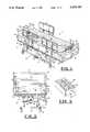
- FIG. 2is an end view of the low air loss bed of FIG. 1 with the footboard removed and some details not shown for purposes of clarity.
- FIG. 3is a schematic diagram of the air plumbing assembly of the low air loss bed of FIG. 1.
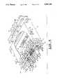
- FIG. 4is a perspective view of the air control box of the low air loss bed of FIG. 1 showing the cover in cutaway view to show the interior components of the air box.
- FIG. 5is a perspective view of the pendent control of the low air loss bed of FIG. 1.
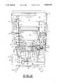
- FIG. 6is an end view of the low air loss bed of FIG. 1 with the head portion raised to show the construction of the frame and the components mounted thereto.
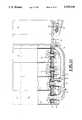
- FIG. 7is an end view of the low air loss bed of FIG. 1 with the foot portion raised to show the construction of the frame and the components mounted thereto.
- FIG. 8is a sectional view of the air box of the low air loss bed of FIG. 1 taken along the lines 8--8 in FIG. 4.
- FIGS. 9A and 9Bare cross-sectional views taken along the lines 9A--9A and 9B--9B, respectively, through the manifold assembly of the air box as shown in FIG. 8.
- FIG. 10is a schematic electrical diagram of the low air loss bed of FIG. 1.
- FIG. 11is a partial longitudinal section taken through the foot baseboard of the low air loss bed of FIG. 1.
- FIG. 12is a plan view of the bracket and air gauges of the low air loss bed of FIG. 1.
- FIG. 13is an end view of the bracket and air gauges of FIG. 12.
- FIG. 14is a top view of the heating element removed from the air box as shown in FIG. 4.
- FIG. 15is a side view of the heating element of FIG. 14.
- FIG. 16is a perspective view of an alternative embodiment of the air control box of the low air loss bed of the present invention.
- FIG. 17is an end view similar to FIG. 7 showing an alternative construction of the low air loss bed of the present invention.
- FIG. 18is a back view of the manifold assembly removed from the air box of FIG. 16.
- FIG. 19is a cross-sectional view of the manifold assembly of FIG. 16 taken along the lines 19--19 in FIG. 18.
- FIG. 20is a perspective view of the pendent control for the air box of FIG. 16.
- FIG. 21is a perspective view of the quick dump and full inflate mechanisms of the alternative construction of the low air loss bed shown in FIG. 17 removed from beneath the bed and enlarged to show the details of the construction of these operating features.
- a bed 10including a frame 12.
- the frame 12is comprised of a plurality of sections 14', 14", 14'" and 14"", hinged at the points 44', 44" and 44'", and end members 16.
- Cross-members 18(FIGS. 6, 7 and 17) and braces 19 (FIGS. 7 and 17) are provided for additional rigidity.
- the frame 12is provided with headboard 20 at one end and a foot board 21 at the other end.
- the respective head 20 and foot 21 boardsare actually constructed of two boards, 20' and 20", and 21' and 21", respectively, which are stacked one on top of the other by the vertical slats 25 on which the boards 20', 20", 21' and 21" are mounted.
- the base 22is mounted on casters 30 at the corners of the base 22.
- a foot pedal 42is provided for braking and steering the casters 30.
- Sub-frame 27is comprised of cross beams 29, hoop brace 35, and longitudinal beams 31 (see FIGS. 2, 6, 7 and 17). Sub-frame 27 is provided at the corners with uprights 33, having tabs 33' thereon, for mounting of IV bottles and other equipment.
- the sub-frame 27may be raised and lowered relative to the base 22 by means of a vertical height adjustment mechanism, not all of the details of which are shown. Height is adjusted by rotation of axle 36 under influence of a power screw, hidden from view in FIGS. 2 and 7 by drive tunnel beam 37, which is powered by a motor which is also hidden from view.
- Axle 36is journaled in the ears 38 which are mounted to the longitudinal beams 31 of sub-frame 27. Power is transferred from the power screw to axle 36 by means of eccentric levers 39, the axle 40 of which is journaled in drive tunnel beam 37.
- Sub-frame 27rises on levers 32 which are pivotally mounted to the cross-beams of base 22 by members 34.
- the section 14" of frame 12is mounted to the longitudinal beams 31 of sub-frame 27 by support members 41 (see FIG. 6).
- the details of this pivotingare known in the art and are not shown for purposes of clarity, although the motors are located within the boxes shown at 45 and the circuitry for those functions is contained within box 43 (FIGS. 7 and 17).
- Supports 17are provided on the cross member 18 under head baseboard 52 which rest on the longitudinal beams 31 of sub-frame 27 when head baseboard 52 is horizontal.
- cross-bar 47When foot baseboard 46 is raised, cross-bar 47 rises with it by means of the pivoting connection created by cross-bar 47 and the notches 49 in brace 19 (cross-bar 47 is shown detached from braces 19 in FIG. 7 for purposes of clarity).
- the sets of notches 49provide a means of adjusting the height to which foot baseboard 46 can be raised, foot baseboard 46 pivoting upwardly on brackets 51 which are pivotally mounted to the longitudinal beams 31 of sub-frame 27.
- the tips 53 of cross-bar 47rest on longitudinal beam 31 when foot baseboard 46 is lowered to the horizontal.
- Side rails 81are mounted to brackets 83 (see FIG. 6) which are pivotally mounted to the mounting brackets 85 mounted on the underside of head baseboard 52.
- Side rails 87are mounted to brackets 89 (see FIG. 7), and brackets 89 are pivotally mounted to the mounting brackets 91.
- Mounting brackets 91are affixed to the braces 19 on the underside of foot baseboard 46.
- the frame 12is provided with a feet baseboard 46, a leg baseboard 48, a seat baseboard 50 and a head baseboard 52 (shown in shadow lines in FIG. 3), each being mounted to the corresponding section 14', 14", 14'" and 14"" of the frame 12 by means of rivets 54 (see FIG. 11).
- the baseboards 46-52are provided with male snaps 56 (FIG. 11) along their edges.
- a plurality of air bags 58are provided with flaps 60, each of which is supplied with female snaps 62 which mate with male snaps 56.
- Flaps 60may be provided with a strip of VELCRO tape 55, and the edges of baseboards 46-52 may be provided with a complementary strip of VELCRO hooks 57, to secure each air bag 58 in place.
- flap 60 and baseboards 46-52may be provided with both VELCRO and snap fastening means.
- the baseboards 46-52are also provided with a plurality of holes 64.
- the holes 64' and 64" at the extreme end of the feet baseboard 46are provided with receptacles 66' and 66".
- the hole 64'" at the extreme end of the head baseboard 52is also provided with a receptacle 66'".
- the air bags 58are substantially rectangular in shape, and are constructed of a coated fabric or similar material through which gas, including water vapor, can move, but which water and other liquids will not penetrate.
- the fabric sold under the trademark "GORE-TEX”is one such suitable material.
- the air bags 58may be constructed in a "low air loss" conformation.
- the low air loss air bag shown at reference numeral 59 in FIGS. 2 and 11is a composite of a gas impermeable fabric, which makes up the bottom 72 and the walls 61 of the air bag 58, and the gas permeable fabric described above, which makes up the top 63 of the air bag.
- the top 63 and walls 61are stitched or otherwise joined at shadow lines 63'.
- the gas impermeable fabricis, for instance, a polymer-coated nylon.
- the low air loss air bag 59allows the pressurization of the air bag 59 with a smaller flow of gas than is required to inflate air bags 58, which results in the possibility of maintaining sufficient pressure with just one blower 108 operating while using low air loss air bags 59.
- Each air bag 58(it should be understood throughout the specification that, when reference is made to an air bag 58, the air bag could also be an air bag 59 constructed in the low air loss conformation) is provided with a flanged nipple 70 sewn in place on the bottom 72 of the air bag 58 between a patch 74 and the bottom 72 of the air bag.
- Patch 74is provided with a hole (not numbered) of the same dimension as the inside diameter of the flanged nipple 70, and flanged nipple 70 is held in place by the attachment of patch 74 to the bottom 72 of air bags 58 by stitching or other means around the external edge of the flange 71 of the flanged nipple 70.
- Each air bag 58is mounted separately on the baseboards 46-52 by snapping the female snaps 62 in the flaps 60 of each of the air bags 58 over the male snaps 56 on the edges of the baseboards 46-52 or with the VELCRO tape 55 and hooks 57, or both.
- the flanged nipple 70 on the bottom inside 72 of the air bag 58projects through the holes 64 in the baseboards 46-52 over which the air bags 58 are positioned.
- An 0-ring 68is provided in a groove (not numbered) around each of the flanged nipples 70 to insure a relatively gas-tight fit between the flanged nipple 70 and the corresponding baseboard 46-52 through which the flanged nipples 70 project.
- VELCRO tape 55 and hooks 57may also be provided to secure air bags 58 in addition to, or in place of, snaps 56 and 62.
- spring clip 73may be inserted through nipple 70 of air bag 58.
- the hoop portion 75 of spring clip 73is squeezed (through the fabric of air bag 58), causing the flanges 77 on the ends of the shank portion 79 of spring clip 73 to move toward each other so that they can enter the hole 64.
- flanges 77spring apart, and will not permit the removal of nipple 70 from hole 64 without again squeezing the hoop portion 75 of spring clip 73.
- FIG. 6there is shown an end view of a bed constructed according to the present invention.
- Brace 102is secured to the cross beam 29 of sub-frame 27 by means of bolts 104.
- Blowers 108are mounted to the brace 102 by means of bolts 110 through the mounting plates 112 which are integral with the blower housing 116.
- a gasket, piece of plywood or particle board (not shown), or other sound and vibration dampening materialmay be interposed between mounting plates 112 and brace 102.
- a strip of such materialis inserted between brace 102 and cross beam 29, and is shown at reference numeral 69.
- the blowers 108include integral permanent split capacitor electric motors 114.
- blowers 108move air out of the blower housings 116, through the blower funnels 118 and up the blower hoses 120 to the air box funnels 122 and on into the air box 124 (see FIGS. 3 and 6). Blowers 108 receive air from filter box 96 through hoses 98. The filter box 96 is retained within frame 100 for ease in removal (see FIGS. 7 and 17).
- the second blower 108is provided to increase the volume which may be delivered to the air bags 58, thereby increasing the air pressure within air bags 58.
- a cover (not shown) lined with sound absorbing materialmay also be provided to enclose blowers 108 and thereby reduce noise.
- the air control box 124is an airtight box mounted on the underside of the baseboard 52 by brackets 125, and is shown in more detail in FIG. 4.
- Air box 124is provided with a manifold assembly 126 held to the front of air box 124 by screws 119.
- Manifold assembly 126is provided with a manifold plate 145 having holes (not numbered) therein for connection to a means for changing the amount of air supplied to the air bags 58 mounted to baseboards 46-52 in the region of the head, back, seat, leg, and feet respectively.
- Gasket 115prevents the escape of air from between air box 124 and manifold plate 145.
- the means for changing the amount of air supplied to the air bags 58takes the form of a plurality of valves, indicated generally at reference numerals 128-136.
- Each of the valves 128-136is provided with a motor 138 having a nylon threaded shaft 139 (see FIGS. 4, 8, 9A and 9B) mounted on the drive shaft (not numbered) of each motor 138 and held in place by set screw 149 in collar 148.
- Plug 140moves rotatably in and out along the threaded shaft 139 when limit pin 141 engages one or the other of the supports 142 which are immediately adjacent that particular plug 140 and which hold the motor mounting bracket 143 to the back of the full inflate plate 144.
- Full inflate plate 144 having openings 202 therein forming part of valves 128-136is mounted to the back of the manifold plate 145 by hinges 146 (see FIGS. 9A and 9B).
- a gasket 147is provided to prevent the escape of air from between the full inflate plate 144 and manifold plate 145.
- the motors 138are not provided with limit switches, the movement of plug 140 back and forth along the threaded shaft 139 of each motor 138 being limited by engagement of plug 140 with the opening 202 as plug 140 moves forward and by the engagement of the back side of plug 140 with collar 148 as plug 140 moves back on threaded shaft 139.
- An 0-ring 204is provided on plug 140 which is compressed between plug 140 and opening 202 as plug 140 moves forward into opening 202. This compression continues until the load on motor 138 is sufficient to cause it to bind and stop.
- the 0-ring 206which is provided on collar 148 operates in similar fashion when engaged by the back side of plug 140.
- Threaded shaft 139is free to reverse direction and turn such that the load created by the compression of 0-rings 204 or 206 is released by the turning of threaded shaft 139, and plug 140 will rotate with threaded shaft 139 until limit pin 141 contacts support 142, stopping the rotation of plug 140 and causing it to move along shaft 139 as it continues to turn.
- a dump plate 150is mounted on the outside of manifold plate 145 by means of hinges 151 (see FIGS. 9A and 9B).
- a gasket 106is provided to prevent the escape of air from between the manifold plate 145 and the dump plate 150.
- the dump plate 150is provided with couplers 153, the interiors of which are continuous with the holes in manifold plate 145 when dump plate is in the position shown in FIGS. 9A and 9B, for connection of the appropriate bed frame gas supply hoses 174-182, as will be explained.
- Block 154is attached to dump plate 150 by means of screws 155, and serves as a point at which the cable 156 can be anchored, by means of nut 157, so that a line 158 can slide back and forth within cable 156 to allow the dump plate 150 to be selectively pivoted away from manifold plate 145 on hinge 151.
- the line 158is secured to the manifold plate 145 by the threaded cable end and locknut 159. Line 158 is secured at its other end to the bracket 183 mounted on tube 190 (see FIG. 7).
- Bed frame 12is provided with quick dump levers 165 on both sides thereof, the quick dump levers 165 being connected by tube 190 so that both levers 165 provide a remote control for operation of dump plate 150 by causing the movement of line 158 through cable 156.
- eccentric lever arm 181pulls on line 158, cable 156 being anchored on bracket 183, so that line 158 moves through cable 156.
- the details of the anchoring of cable 156 and movement of line 158 therethrough under the influence of lever arm 181are the same as those for the anchoring of cable 160' and movement of line 162' therethrough under the influence of lever arm 185' as shown in enlarged perspective view in FIG. 21.
- Movement of line 158causes dump plate 150 to pivot away from manifold plate 145, allowing the air in air bags 58 to escape through manifolds 76-84 and bed frame gas supply hoses 174-182 to the atmosphere from the opening thus created between manifold plate 145 and dump plate 150 so that air bags 58 will rapidly deflate.
- a separate cable 160passes through manifold plate 145 in threaded fitting 161 so that line 162 can slide back and forth therein.
- the line 162is anchored in the full inflate plate 144 by means of nut 163, which allows the full inflate plate 144 to pivot away from the manifold plate 145 on hinge 146.
- Pivoting of full inflate plate 144 away from manifold plate 145 in this mannerremoves full inflate plate 144, motor mounting bracket 143, and all other parts mounted to those parts, from the flow of air to allow the unrestricted entry of the air in air box 124 into the couplers 153 of valves 128-136 and on into bed frame gas supply hoses 174-182, resulting in the rapid and full inflation of air bags 58 to facilitate patient transfer or other needs.
- Line 162is anchored at its other end on lever arm 185 (FIGS. 7, 17 and 21) which is attached to the bar 195 upon which full inflate knob 193 is mounted.
- a coil spring 201is provided to protect line 162 as it is effectively wrapped around bar 195 when knob 193 is turned as will be described.
- Bed frame 12is provided with full inflate knobs 193 on both sides thereof, the full inflate knobs 193 being connected by bar 195 so that both control the movement of line 162 through cable 160.
- Cable 160is affixed to bracket 187 by threaded cable end 199, which is mounted on the DELRIN bearing 209 which is integral with support member 210 and which receives bar 195 so that rotation of full inflate knobs 193 causes line 162 to slide therein, pivoting full inflate plate 144 on hinge 146.
- Air box funnel 122is provided with a one-way flapper valve 117 so that air will not escape from the air box 124 when only one blower 108 is being operated.
- Back plate 121is held in place on air box 124 by screws 123, and gasket 127 is provided to prevent the loss of air from between air box 124 and back plate 121.
- the air box 124is provided with a heating element indicated generally at 129 and shown in FIGS. 14 and 15. Screws 131 secure heating element 129 in place on the bottom of air box 124, effectively partitioning air box 124 into two compartments. Since air enters the air box 124 in one compartment (i.e., behind heating element 129) and leaves the air box 124 from the other compartment, a flow of air must pass through the space 135 between bulkhead 133 and the mounting bracket 137 of heating element 129, being mixed and heated as it does.
- Wires 167 i and 167 oprovide power to heating element 127, the wire 167 i connecting thermostats 169 and 171 and heater strip 172 in series.
- Heater strip 172is suspended in space 135 by insulated posts 173 which are secured in the flanges 175 and 177 of bulkhead 133 and mounting bracket 137, respectively.
- Thermostat 169switches off at 140° F.
- thermostat 171switches off at 180° F.
- heater strip 172must cool to 120° F. for thermostat 169 to come back on.
- Thermostat 171is merely redundant and included for safety purposes. Both thermostats 169 and 171 reset automatically, the thermostat 171 coming back on at 140° F.
- the electric motors 114 of blowers 108are switched on, forcing or pumping air (or other gases) received from filter box 96 through hoses 98 up the blower hoses 120, through one-way valves 117, and into air box 124.
- the airescapes from the air box 124 through valves 128-136 into the respective bed frame gas supply hoses, 174-182 (see FIG. 3).
- a separate bed frame gas supply hoseis provided for the feet 174, legs 176, seat 178, back 180 and head 182, and each supplies a separate flow of gas to the manifolds 76-84.
- the feet baseboard 46mounted on the section 14' of frame 12, is provided with a feet gas manifold 76.
- leg 48 and seat 50 baseboards, and their corresponding frame sections 14" and 14'"are provided with a leg gas manifold 78 and a seat gas manifold 80, respectively.
- the head baseboard 52, and its corresponding section 14""is provided with two separate gas manifolds, a back gas manifold 82 and a head gas manifold 84.
- a T-intersect 86is provided from the feet gas manifold 76 to route feet extension hose 88 to the receptacles 66' and 66" in the holes 64' and 64" at the extreme ends of the feet baseboard 46 (see FIGS. 7 and 11).
- An extension hose T-intersect 90is provided in the feet extension hose 88 to provide the connection to the hole 64" in the feet baseboard 46.
- Clamps 65are provided to hold the feet extension hose 88 in place on the receptacles 66' and 66" and on T-intersect 86 as well as extension hose T-intersect 90.
- the head baseboard 52likewise extends beyond the end member 16 of frame 12 at the head end of the bed (FIGS. 3 and 6), and T-intersect 92 is provided from the head gas manifold 84 to provide gas to the hole 64'" at the extreme end of the head baseboard 52 by means of the head extension hose 94.
- a clamp 65is provided to retain head extension hose 94 on T-intersect 92 and on the receptacle 66'" (not shown).
- each of the bed frame gas supply hoses 174-182is continuous with a corresponding gas manifold 76-84, the amount of air supplied to each gas manifold 76-82 can be varied using the valves 128-136 on the air box 124. Since each of the valves 128-136 controls the amount of air supplied to one of the manifolds 76-84, each valve 128-136 controls the amount of air supplied to the set of air bags 58 located directly above an individual gas manifold 76-84. Each of the valves 128-136 is opened and closed by the movement of plug 140 along threaded shaft 139 as motor 138 is activated in one direction or the other as described above under the control of switches 186 on pendent control 188.
- the motors 138are brush-type DC control motors powered by current from the wires 184 i and 184 o under control of switches 186.
- Five of the switches 186 on pendent control 188are double pole, double throw, three-position, spring return-to-center-off rocker switches, and are connected to motors 138 through electric cable 170, which plugs into the 14-pin connector 164 in manifold plate 145 (see FIG. 10).
- the sixth switch 186is the main power switch, as will be explained, which is likewise connected through 14-pin connector 164 in manifold plate 145.
- a cradle 179may be provided for mounting of pendent control 188 on head board 20, foot board 21, or side rails 81 and 87.
- Color coding(not shown) of the control valve rocker switches 186 and the bed frame sections 14'-14"" (i.e., section 14' is colored pastel purple and the switch 186 which operates valve 128 is colored pastel purple, section 14" is colored pastel pink and the switch 186 which operates valve 130 is likewise colored pastel pink, etc.) may be provided to enable patients or health care personnel to correlate the individual valve to the particular set of air bags which it controls conveniently without having to read the labeling which may also be provided.
- the pastel colorsare used for their aesthetic appearance.
- the color codingis inexpensive and easily understood so that the bed can be quickly adjusted, and is universally used and recognized in innumerable instances.
- the frame 12is hinged at 44', 44" and 44'", allowing the baseboards 46 and 52 to be raised from the horizontal for the comfort of the patient or, perhaps, for therapeutic purposes.
- the deviation from the horizontalplaces a disproportionate amount of the patient's weight on the air bags 58 over the legs 48 and seat 50 baseboards.
- FIGS. 3 and 21show an alternative embodiment of the present invention. However, because the embodiment shown in FIG. 21 shows the same means for routing a flow of gas from the gas source to the set of air bags supporting the heavier portions of the patient as the embodiment shown in FIGS.
- Airproceeds from air box 124 through line 93' directly to valve 95' without passing through any of the valves 128-136 or bed frame gas supply hoses 174-182.
- Valve 95'is opened to allow air to pass into line 97'.
- a second valve 105'is located in line 93' which may be opened to allow air to pass into line 99'.
- valve 95'is a two position valve which is either open or closed, and is operated by a pivotally attached lever arm 107' which is pivotally attached by cable 109' to the frame section 14' of the head baseboard 52 (not shown) so that when head baseboard 52 is raised from the horizontal, valve 95' is automatically opened allowing a flow of gas to enter line 97' through tee intersect 197'.
- the valve 95'returns to the closed position when head baseboard 52 is lowered due to the action of spring 111' anchored to tee 197'.
- Another valve 67' in tee intersect 197'is continuously adjustable by means of knob 67".
- the second valve 105'is provided with a continuously adjustable knob 113' which may be set by the operator to allow as much additional air to pass into line 99' from line 93' as may be required, depending upon the weight of the patient, to support the patient's legs.
- the flow of additional air into the seat 80 and legs 78 (not shown in FIG. 21) gas manifoldsprovides the additional air pressure needed to provide the support which may be required for air bags 58 when the patient's weight is concentrated on that set of air bags 58 by any patient likely to be encountered.
- the air pressure in the air bags 58 over seat baseboard 50 or legs baseboard 48, or both,may also be fine-tuned by the use of valve 132 and/or valve 134.
- air chucks 212are provided in the dump plate 150 which communicate, in airtight sealing relationship, to the opening in each of the couplers 153 of valves 128-136.
- air pressure lines 213 and corresponding air pressure gauges 214see FIG. 12 and 13
- Air pressure gauges 214are mounted to cross bar 215, which is mounted by means of screws 216 to brackets 217.
- the brackets 217are sized to allow the air pressure gauges 214 to be mounted to either the headboard 20 or foot board 21, by slipping over the board as shown in FIG. 1.
- FIG. 10there is shown a schematic electrical diagram of the low air loss bed of the present invention.
- Alternating currententers the circuitry from electric cord 218, and is split to power the motors (not shown) for adjustment of the height and toe-to-toe angle of frame 12 through lead 220 as is known in the art.
- Currentis also routed through current breaker 221 to transformer 222.
- the low voltage of the A.C. power from transformer 222is regulated by voltage regulator 224, which provides D.C. current to motors 138 on the inside of air box 124 and the switches on pendent control 188 by wires 189 i and 189 o , the electrical cable 170 passing through manifold plate 145 by means of 9-pin connector 166.
- Switch 186 on pendent control 188is a two-position, maintain contact switch which activates the relay 192.
- Relay 192activates the circuit containing thermostat 194 as well as the relay portion of time delay 198.
- Thermostat 194includes a sensor 200 located in seat gas manifold 80, shown schematically in FIG. 3, and when the circuit containing thermostat 194 is closed due to the temperature of the air in seat gas manifold 80, the pilot light 196 comes on indicating that the circuit has been completed to the time delay portion of time delay 198.
- Thermostat 194also includes a control 202 (see FIGS. 2, 7 and 17) for adjustment of the temperature of the gas in seat gas manifold 80, and a thermometer gauge 209 for continuous monitoring of that temperature. If this circuit stays completed for a predetermined period of time, the relay portion of time delay 198 is energized so that the circuit including wires 167 i and 167 o and heating element 172 is completed.
- Relay 192also activates the circuit which includes toggle switch 240, by which the operator may select one or both of the blowers 108. Pilot lights 238 and capacitors 236 are included in both circuits to the motors 114 of blowers 108.
- Limit switches 226 and 228are provided in manifold plate 145 and on full inflate plate 144, respectively (see FIGS. 4, 8 and 9A).
- Limit switch 226is closed when push button 230 is engaged by dump plate.
- push button 230is disengaged by the movement of dump plate 150 away from manifold plate 145 under the influence of levers 165, the circuit is opened and blowers 108 are shut off.
- Limit switch 228is affixed to full inflate plate 144 by screws 232, and the circuit is open when lever arm 234 engages manifold plate 145.
- limit switch 228is closed, activating the buzzer which is incorporated into the voltage regulator 224.
- FIGS. 16-20there is shown an alternative embodiment of the air box 124 and control system for the valves 128-136 in air box 124, in which those parts which correspond to the component parts shown in FIGS. 1-15 are shown with the primed designation of the same reference numerals used in FIGS. 1-15 to the extent possible.
- the air box 124'is shown in FIG. 16 with a manifold assembly 126', held onto air box 124' by screws 119' with gasket 115' therebetween.
- Air box 124'is held to the bottom of head baseboard 52' by means of mounting brackets 125'.
- Air box 124'is shown with baffles 246 and 247 mounted to the inside of air box 124' by screws (not shown) through the flanges 248 and 249 respectively, to insure adequate mixing of the air inside the air box 124', but one or both of the baffles 246 or 247 could be replaced by a heating element (not shown) as discussed in connection with the description of FIGS. 1-15.
- Manifold plate 145'is provided with couplers 153' which provide the point of connection for control cables 250 and bed frame gas supply hoses 174'-182'.
- Each control cable 250is anchored in stopper 252 by collar 254.
- Stopper 252is sized to fit tightly into couplers 153', the set screw 251 retaining it therein.
- Each line 256slides back and forth within control cable 250 under the influence of its adjustment knob 258 in pendent control 188' as the adjustment knob 258 is moved in and out of threaded hole 257 on threads 259, carrying nut 260 and line 256 with it.
- Control pad 188'is provided with spring-loaded bracket 262 to allow it to be releasably hung on the head board 20' (not shown) or footboard 21' (FIG. 17).
- Line 256passes through stopper 252 and terminates on bit 264.
- the threads 265 of bit 264are received by threads on the inside of air adjustment rod 266, and the threads 267 at the other end of air adjustment rod 266 are received by threads on the inside of plug 140', the collar 272 preventing any rotation therebetween.
- Air adjustment rod 266is received within air adjustment tube 268 and spring 270, the air adjustment tube 268 and spring 270 being end-to-end around air adjustment rod 266.
- Spring 270provides constant tension which movement of adjustment knob 258 must overcome to push plug 140' out of the opening of tee 274, insuring that plug 140' is always biased toward the opening in tee 274.
- the amount of constant tensioncan be adjusted by screwing air adjustment tube 268 into or out of the threads on the inside of stopper 252 which receive the threads 269 on air adjustment tube 268.
- FIGS. 16-20the embodiment of the present invention shown in FIGS. 16-20 is provided with a means for fully inflating the air bags 58' (not shown).
- Line 162'is anchored at one end on lever 185' which is attached to the DELRIN bearing 209 which is integral with support member 210' and which receives bar 195' upon which full inflate knobs 193' are mounted.
- Cable 160'is affixed to bracket 187' which is mounted on the support member 210' which receives bar 195' so that rotation of either of the knobs 193' will cause line 162' to slide therein. Referring to FIG.
- cable 160'is anchored on its other end on fitting 278 in manifold plate 145' by nut 280.
- Line 162'passes through fitting 278 and is anchored in fitting 284 by nut 285 in horizontal member 286.
- Horizontal member 286is secured on one end to the inside of manifold plate 145' by screw 287 through hinge 288 and on the other end to hinge 290.
- Hinge 290is secured to one end of vertical member 292, which has a similar hinge 294 at the other end.
- the hinge 294attaches to one side of full inflate plate 144' by rivets 295.
- Full inflate plate 144'is secured on its other side to manifold plate 145' by means of screw 296 through hinge 146'.
- Full inflate plate 144'is provided with a flange 298 having holes 300 therein spaced at intervals so as to receive the ends of coil springs 302 which wrap around the inside tees 274, holding full inflate plate 144' up tightly against the air intake to the inside tees 274 of valves 128'-136'.
- Gasket 147'is applied to full inflate plate 144' to insure an airtight fitting around the openings of inside tees 274 to valves 128'-136'.
- knobs 193' and full inflate plate 194'are the same as the operation of knobs 193 and full inflate plate 144' except that full inflate plate 144' is biased toward the position in which the flow of air through valves 128'-136' is blocked rather than away from that position, as is the case with full inflate plate 144'. Again, this bias allows knobs 193' to act as releases.
- Rapid deflation of air bags 58is provided by quick disconnect 304 (FIG. 21).
- a T-intersect 306is provided in each of the bed frame gas supply hoses 174'-182' (see FIG. 17).
- a quick disconnect hose 308connects each of the T-intersects 306 in each of the respective bed frame gas supply hoses 174'-182' to the quick disconnect 304 (FIG. 21).
- Quick disconnect 304is provided with a receptacle plate 310 with five receptacles 311 to which the quick disconnect hoses 308 are attached, and dump plate 150' which is hinged to receptacle plate 310 by hinge 314.
- Gasket 313is provided to help insure an air-tight seal between receptacle plate 310 and dump plate 150'.
- An eccentric, pivoted bell crank lever 316is pivotally attached at one end to lever 321, and at the other end to a hinge 318 which is attached to dump plate 150'.
- Lever 321is secured to the tube 190' which connects the two quick disconnect levers 165' so that rotation of either of the quick dump levers 165' has the result of pivoting dump plate 150' downwardly away from receptacle plate 310 so that air can escape to the atmosphere from each of the bed frame gas supply hoses 174'-182'.
Landscapes
- Health & Medical Sciences (AREA)
- Nursing (AREA)
- Life Sciences & Earth Sciences (AREA)
- Animal Behavior & Ethology (AREA)
- General Health & Medical Sciences (AREA)
- Public Health (AREA)
- Veterinary Medicine (AREA)
- Invalid Beds And Related Equipment (AREA)
Abstract
Description
Claims (39)
Priority Applications (1)
| Application Number | Priority Date | Filing Date | Title |
|---|---|---|---|
| US07/251,948US5005240A (en) | 1987-11-20 | 1988-09-29 | Patient support apparatus |
Applications Claiming Priority (2)
| Application Number | Priority Date | Filing Date | Title |
|---|---|---|---|
| US12438287A | 1987-11-20 | 1987-11-20 | |
| US07/251,948US5005240A (en) | 1987-11-20 | 1988-09-29 | Patient support apparatus |
Related Parent Applications (1)
| Application Number | Title | Priority Date | Filing Date |
|---|---|---|---|
| US12438287AContinuation | 1987-11-20 | 1987-11-20 |
Publications (1)
| Publication Number | Publication Date |
|---|---|
| US5005240Atrue US5005240A (en) | 1991-04-09 |
Family
ID=26822513
Family Applications (1)
| Application Number | Title | Priority Date | Filing Date |
|---|---|---|---|
| US07/251,948Expired - LifetimeUS5005240A (en) | 1987-11-20 | 1988-09-29 | Patient support apparatus |
Country Status (1)
| Country | Link |
|---|---|
| US (1) | US5005240A (en) |
Cited By (52)
| Publication number | Priority date | Publication date | Assignee | Title |
|---|---|---|---|---|
| US5235713A (en)* | 1990-11-06 | 1993-08-17 | Bio Clinic Corporation | Fluid filled flotation mattress |
| US5373595A (en)* | 1993-03-12 | 1994-12-20 | Irvin Industries Canada Ltd. | Air support device |
| US5509154A (en)* | 1994-11-01 | 1996-04-23 | Select Comfort Corporation | Air control system for an air bed |
| US5560057A (en)* | 1994-07-01 | 1996-10-01 | Madsen; Roger T. | Turning air mattress |
| US5586346A (en)* | 1994-02-15 | 1996-12-24 | Support Systems, International | Method and apparatus for supporting and for supplying therapy to a patient |
| US5606754A (en) | 1989-03-09 | 1997-03-04 | Ssi Medical Services, Inc. | Vibratory patient support system |
| WO1997032509A1 (en)* | 1996-03-05 | 1997-09-12 | L & P Property Management Company | Air bed control |
| US5794288A (en)* | 1996-06-14 | 1998-08-18 | Hill-Rom, Inc. | Pressure control assembly for an air mattress |
| US5873137A (en)* | 1996-06-17 | 1999-02-23 | Medogar Technologies | Pnuematic mattress systems |
| DE20206765U1 (en) | 2002-04-27 | 2002-07-18 | Joh. Stiegelmeyer GmbH & Co. KG, 32051 Herford | Sick or nursing bed with side panels |
| US20030192127A1 (en)* | 1998-08-24 | 2003-10-16 | The Nautilus Group, Inc. | Air bed |
| US6698046B1 (en) | 2001-03-26 | 2004-03-02 | Sunflower Medical, L.L.C. | Air mattress control unit |
| US20040064895A1 (en)* | 2002-10-07 | 2004-04-08 | Hochschild Arthur A. | Stabilized shape retentive air-inflated bed |
| US20040128765A1 (en)* | 1999-12-29 | 2004-07-08 | Hill-Rom Services, Inc. | Foot controls for a bed |
| US20040158927A1 (en)* | 2000-02-25 | 2004-08-19 | Hill-Rom Services, Inc. | Air fluidized bladders for a bed |
| US20060156473A1 (en)* | 2004-12-15 | 2006-07-20 | Chambers Kenith W | Quick connector for multi-media |
| US20070136949A1 (en)* | 2005-12-19 | 2007-06-21 | Sandy Richards | Patient support having an extendable foot section |
| US20070144933A1 (en)* | 2005-05-24 | 2007-06-28 | Searete Llc, A Limited Liability Corporation Of The State Of Delaware | Actuatable cushioning elements |
| US20070266499A1 (en)* | 2006-05-09 | 2007-11-22 | Hill-Rom Services, Inc. | Pulmonary mattress |
| US20080098529A1 (en)* | 2006-10-26 | 2008-05-01 | Thierry Flocard | Device and method for controlling humidity at the surface of a supporting item of the mattress type |
| US20080117042A1 (en)* | 2005-05-24 | 2008-05-22 | Searete Llc, A Limited Liability Corporation Of The State Of Delaware | Actuatable cushioning elements |
| US20080143521A1 (en)* | 2005-05-24 | 2008-06-19 | Searete Llc | Energy dissipative cushioning elements |
| US20090013470A1 (en)* | 2007-05-31 | 2009-01-15 | Richards Sandy M | Pulmonary mattress |
| US20090089930A1 (en)* | 2007-10-09 | 2009-04-09 | Eduardo Rene Benzo | Bed with Adjustable Patient Support Framework |
| US20090094744A1 (en)* | 2007-10-14 | 2009-04-16 | Eduardo Rene Benzo | Support Surface That Modulates to Cradle a Patient's Midsection |
| US20090094745A1 (en)* | 2007-10-14 | 2009-04-16 | Eduardo Rene Benzo | Modulating Support Surface to Aid Patient Entry and Exit |
| US20090094746A1 (en)* | 2007-10-14 | 2009-04-16 | Ferraresi Rodolfo W | Bed With Sacral and Trochanter Pressure Relieve Functions |
| WO2009122123A1 (en)* | 2008-03-31 | 2009-10-08 | Talley Group Limited | Mattress system |
| US20100004567A1 (en)* | 2005-05-24 | 2010-01-07 | Searete Llc, A Limited Liability Corporation Of The State Of Delaware | Wearable/portable protection for a body |
| US7698765B2 (en) | 2004-04-30 | 2010-04-20 | Hill-Rom Services, Inc. | Patient support |
| US7849545B2 (en) | 2006-11-14 | 2010-12-14 | Hill-Rom Industries Sa | Control system for hospital bed mattress |
| US20110024076A1 (en)* | 2008-04-15 | 2011-02-03 | Hill-Rom Services, Inc. | Microclimate management system |
| US20110047703A1 (en)* | 2009-08-31 | 2011-03-03 | Jean-Francois Tarsaud | Lateral tilt device |
| US20110073202A1 (en)* | 2007-01-26 | 2011-03-31 | Rapid Air Llc (A Wisconsin Limited Liability Company) | Multiple Configuration Air Mattress Pump System |
| EP2263498A3 (en)* | 2009-06-19 | 2011-10-19 | Ho Jin Ko | Heating and sterilizing apparatus for bed mattress |
| US20110265898A1 (en)* | 2007-01-26 | 2011-11-03 | Rapid Air Llc (A Wisconsin Limited Liability Company) | Sealed Manifold For Air Pump System |
| US20140173825A1 (en)* | 2011-06-16 | 2014-06-26 | Picard Healthcare Technology (Dongguan) Co. Ltd. | Medical air mattress, method to inflate/deflate a medical air mattress and method to incline the bearing surface of a medical air mattress |
| US8789224B2 (en) | 2000-11-07 | 2014-07-29 | Tempur-Pedic Managemant, LLC | Therapeutic mattress assembly |
| US9049943B2 (en) | 2007-10-18 | 2015-06-09 | Hill-Rom Industries Sa | Mattress structure including low air loss |
| US20150170494A1 (en)* | 2013-12-18 | 2015-06-18 | Medicustek Inc. | Clinical information management system |
| US9192533B2 (en)* | 2013-08-09 | 2015-11-24 | Fairburn Medical Products, LLC | Configurable air diffusion body supports |
| US9308393B1 (en) | 2015-01-15 | 2016-04-12 | Dri-Em, Inc. | Bed drying device, UV lights for bedsores |
| US9329076B2 (en) | 2012-06-21 | 2016-05-03 | Hill-Rom Services, Inc. | Patient support systems and methods of use |
| US9833369B2 (en) | 2012-06-21 | 2017-12-05 | Hill-Rom Services, Inc. | Patient support systems and methods of use |
| US10136735B2 (en) | 2014-11-19 | 2018-11-27 | Polygroup Macau Limited (Bvi) | Systems and methods for air mattress temperature control |
| US20190151175A1 (en)* | 2014-08-18 | 2019-05-23 | Huntleigh Technology Limited | Connector system |
| US10539941B2 (en) | 2005-05-24 | 2020-01-21 | Deep Science, Llc | Energy dissipative cushioning elements |
| CN116172802A (en)* | 2023-03-16 | 2023-05-30 | 浙江大学 | Sickbed convenient for prone position ventilation |
| US12042453B2 (en) | 2019-02-26 | 2024-07-23 | Hill-Rom Services, Inc. | Patient positioning apparatus and mattress |
| US20240277544A1 (en)* | 2023-02-17 | 2024-08-22 | Stryker Corporation | Patient support apparatus with pump |
| US12102577B2 (en) | 2012-06-21 | 2024-10-01 | Hill-Rom Services, Inc. | Mattress bladder control using a bleed valve |
| US12150905B2 (en) | 2018-11-27 | 2024-11-26 | Stryker Corporation | Patient support apparatus with notification system |
Citations (35)
| Publication number | Priority date | Publication date | Assignee | Title |
|---|---|---|---|---|
| US1936960A (en)* | 1933-02-06 | 1933-11-28 | Bowman Abram Hite | Health mattress |
| US2998817A (en)* | 1959-08-07 | 1961-09-05 | Gary Armstrong Stebbins | Inflatable massaging and cooling mattress |
| US3149348A (en)* | 1962-09-04 | 1964-09-22 | Hill Rom Co Inc | Geriatric furniture |
| US3477071A (en)* | 1968-10-14 | 1969-11-11 | John H Emerson | Device for automatically shifting the body of a patient |
| US3480040A (en)* | 1965-10-20 | 1969-11-25 | Dole Valve Co | Single-inlet,double outlet valve |
| US3485240A (en)* | 1967-03-15 | 1969-12-23 | Edmund M Fountain | Hospital bed with inflatable patient turning means |
| US3492988A (en)* | 1967-09-01 | 1970-02-03 | Baltzar Leo De Mare | Pneumatic positioner |
| US3653083A (en)* | 1970-05-11 | 1972-04-04 | Roy Lapidus | Bed pad |
| GB1273342A (en)* | 1968-01-31 | 1972-05-10 | Nat Res Dev | Improvements relating to fluid mattresses |
| US3671151A (en)* | 1970-05-11 | 1972-06-20 | Miracle Pet Products Inc | Combination aquarium pump and gang valve |
| GB1341325A (en)* | 1971-07-09 | 1973-12-19 | Scales J T | Inflatable support appliance |
| US3821821A (en)* | 1972-08-21 | 1974-07-02 | Hill Rom Co Inc | Electrically operable hospital bed |
| US3865500A (en)* | 1973-07-09 | 1975-02-11 | E Strohm Newell | Locking handle |
| US3879776A (en)* | 1974-01-10 | 1975-04-29 | Morris Solen | Variable tension fluid mattress |
| US3909858A (en)* | 1972-07-21 | 1975-10-07 | Watkins & Watson Ltd | Support appliances |
| US3935604A (en)* | 1974-06-10 | 1976-02-03 | Collins Robert A | Support device for lifting and supporting patients |
| US3949438A (en)* | 1973-11-20 | 1976-04-13 | John Tracey Scales | Inflatable support appliance |
| US3958283A (en)* | 1974-08-09 | 1976-05-25 | Hill-Rom Company, Inc. | Elevating and Trendelenburg mechanism for an adjustable bed |
| GB1474018A (en)* | 1974-05-24 | 1977-05-18 | Watkins Watson Ltd | Beds or like support appliances |
| US4025972A (en)* | 1974-08-09 | 1977-05-31 | Hill-Rom Company, Inc. | Elevating and Trendelenburg mechanism for an adjustable bed |
| GB1483045A (en)* | 1974-08-27 | 1977-08-17 | Watkins & Watson Ltd | Inflatable mattresses |
| US4097939A (en)* | 1976-02-18 | 1978-07-04 | Hill-Rom Company, Inc. | Hospital bed |
| US4097940A (en)* | 1976-11-09 | 1978-07-04 | Hill-Rom Company, Inc. | Hospital bed having automatic contour mechanism |
| GB1545806A (en)* | 1976-09-23 | 1979-05-16 | Hopkins L | Fluid mattresses |
| US4279044A (en)* | 1979-11-16 | 1981-07-21 | Owen Douglas | Fluid support system for a medical patient |
| GB1601808A (en)* | 1978-03-17 | 1981-11-04 | Watkins & Watson Ltd | Automatic compensator valve |
| US4488322A (en)* | 1980-02-26 | 1984-12-18 | Hunt William V | Mattress and bed construction |
| GB2141333A (en)* | 1983-06-06 | 1984-12-19 | Mediscus Prod Ltd | Low air loss support appliance |
| US4542547A (en)* | 1982-12-15 | 1985-09-24 | Hiroshi Muroi | Pnuematic mat with sensing means |
| US4559655A (en)* | 1982-08-11 | 1985-12-24 | Hill-Rom Company, Inc. | Bed having articulated frame |
| US4564965A (en)* | 1984-01-17 | 1986-01-21 | Support Systems International, Inc. | Fluidized patient support system |
| US4617690A (en)* | 1985-01-07 | 1986-10-21 | Whittaker Corporation | Inflatable bed patient mattress |
| US4638519A (en)* | 1985-04-04 | 1987-01-27 | Air Plus, Inc. | Fluidized hospital bed |
| US4650159A (en)* | 1983-10-19 | 1987-03-17 | Jidosha Kiki Co., Ltd. | Flow control device |
| US4686722A (en)* | 1983-04-06 | 1987-08-18 | Revalidatie Institut Muiderpoort | Articulated bed with cellular air cushion mattress |
- 1988
- 1988-09-29USUS07/251,948patent/US5005240A/ennot_activeExpired - Lifetime
Patent Citations (37)
| Publication number | Priority date | Publication date | Assignee | Title |
|---|---|---|---|---|
| US1936960A (en)* | 1933-02-06 | 1933-11-28 | Bowman Abram Hite | Health mattress |
| US2998817A (en)* | 1959-08-07 | 1961-09-05 | Gary Armstrong Stebbins | Inflatable massaging and cooling mattress |
| US3149348A (en)* | 1962-09-04 | 1964-09-22 | Hill Rom Co Inc | Geriatric furniture |
| US3480040A (en)* | 1965-10-20 | 1969-11-25 | Dole Valve Co | Single-inlet,double outlet valve |
| US3485240A (en)* | 1967-03-15 | 1969-12-23 | Edmund M Fountain | Hospital bed with inflatable patient turning means |
| US3492988A (en)* | 1967-09-01 | 1970-02-03 | Baltzar Leo De Mare | Pneumatic positioner |
| GB1273342A (en)* | 1968-01-31 | 1972-05-10 | Nat Res Dev | Improvements relating to fluid mattresses |
| US3477071A (en)* | 1968-10-14 | 1969-11-11 | John H Emerson | Device for automatically shifting the body of a patient |
| US3653083A (en)* | 1970-05-11 | 1972-04-04 | Roy Lapidus | Bed pad |
| US3671151A (en)* | 1970-05-11 | 1972-06-20 | Miracle Pet Products Inc | Combination aquarium pump and gang valve |
| GB1341325A (en)* | 1971-07-09 | 1973-12-19 | Scales J T | Inflatable support appliance |
| US3822425A (en)* | 1971-07-09 | 1974-07-09 | J Scales | Inflatable support appliance |
| US3909858A (en)* | 1972-07-21 | 1975-10-07 | Watkins & Watson Ltd | Support appliances |
| GB1442994A (en)* | 1972-07-21 | 1976-07-21 | Watkins Watson Ltd | Support appliances such as beds |
| US3821821A (en)* | 1972-08-21 | 1974-07-02 | Hill Rom Co Inc | Electrically operable hospital bed |
| US3865500A (en)* | 1973-07-09 | 1975-02-11 | E Strohm Newell | Locking handle |
| US3949438A (en)* | 1973-11-20 | 1976-04-13 | John Tracey Scales | Inflatable support appliance |
| US3879776A (en)* | 1974-01-10 | 1975-04-29 | Morris Solen | Variable tension fluid mattress |
| GB1474018A (en)* | 1974-05-24 | 1977-05-18 | Watkins Watson Ltd | Beds or like support appliances |
| US3935604A (en)* | 1974-06-10 | 1976-02-03 | Collins Robert A | Support device for lifting and supporting patients |
| US3958283A (en)* | 1974-08-09 | 1976-05-25 | Hill-Rom Company, Inc. | Elevating and Trendelenburg mechanism for an adjustable bed |
| US4025972A (en)* | 1974-08-09 | 1977-05-31 | Hill-Rom Company, Inc. | Elevating and Trendelenburg mechanism for an adjustable bed |
| GB1483045A (en)* | 1974-08-27 | 1977-08-17 | Watkins & Watson Ltd | Inflatable mattresses |
| US4097939A (en)* | 1976-02-18 | 1978-07-04 | Hill-Rom Company, Inc. | Hospital bed |
| GB1545806A (en)* | 1976-09-23 | 1979-05-16 | Hopkins L | Fluid mattresses |
| US4097940A (en)* | 1976-11-09 | 1978-07-04 | Hill-Rom Company, Inc. | Hospital bed having automatic contour mechanism |
| GB1601808A (en)* | 1978-03-17 | 1981-11-04 | Watkins & Watson Ltd | Automatic compensator valve |
| US4279044A (en)* | 1979-11-16 | 1981-07-21 | Owen Douglas | Fluid support system for a medical patient |
| US4488322A (en)* | 1980-02-26 | 1984-12-18 | Hunt William V | Mattress and bed construction |
| US4559655A (en)* | 1982-08-11 | 1985-12-24 | Hill-Rom Company, Inc. | Bed having articulated frame |
| US4542547A (en)* | 1982-12-15 | 1985-09-24 | Hiroshi Muroi | Pnuematic mat with sensing means |
| US4686722A (en)* | 1983-04-06 | 1987-08-18 | Revalidatie Institut Muiderpoort | Articulated bed with cellular air cushion mattress |
| GB2141333A (en)* | 1983-06-06 | 1984-12-19 | Mediscus Prod Ltd | Low air loss support appliance |
| US4650159A (en)* | 1983-10-19 | 1987-03-17 | Jidosha Kiki Co., Ltd. | Flow control device |
| US4564965A (en)* | 1984-01-17 | 1986-01-21 | Support Systems International, Inc. | Fluidized patient support system |
| US4617690A (en)* | 1985-01-07 | 1986-10-21 | Whittaker Corporation | Inflatable bed patient mattress |
| US4638519A (en)* | 1985-04-04 | 1987-01-27 | Air Plus, Inc. | Fluidized hospital bed |
Non-Patent Citations (36)
| Title |
|---|
| Brochure Entitled "Clinitron-A New Therapy"; Support Systems International (France, U.S.) (Undated). |
| Brochure Entitled "Mark V-A Technical Information"; Mediscus Products, Inc. (U.S.) (Approx. 12/84). |
| Brochure Entitled "Mediscus Air Bed Mk V"; Mediscus Products, Ltd. (England). |
| Brochure Entitled "Mediscus Air Bed Mk VA"; Mediscus Products, Ltd. (England) (Undated). |
| Brochure Entitled "The Low Air Loss Bed System-A Controlled Air System for Patient Support"; Mediscus Products, Ltd. (England) (Undated). |
| Brochure Entitled "The Mediscus HOME-CARE Versatile Air Bed"; Mediscus Products, Ltd. (England) (Undated). |
| Brochure Entitled "The Mediscus Mark V-A Pressure Treatment System . . ."; Mediscus Products, Inc. (U.S.) (Approx. 12/84). |
| Brochure Entitled "The Mediscus Minor"; Mediscus Products, Ltd. |
| Brochure Entitled Clinitron A New Therapy ; Support Systems International (France, U.S.) (Undated).* |
| Brochure Entitled Mark V A Technical Information ; Mediscus Products, Inc. (U.S.) (Approx. 12/84).* |
| Brochure Entitled Mediscus Air Bed Mk V ; Mediscus Products, Ltd. (England).* |
| Brochure Entitled Mediscus Air Bed Mk VA ; Mediscus Products, Ltd. (England) (Undated).* |
| Brochure Entitled The Low Air Loss Bed System A Controlled Air System for Patient Support ; Mediscus Products, Ltd. (England) (Undated).* |
| Brochure Entitled The Mediscus HOME CARE Versatile Air Bed ; Mediscus Products, Ltd. (England) (Undated).* |
| Brochure Entitled The Mediscus Mark V A Pressure Treatment System . . . ; Mediscus Products, Inc. (U.S.) (Approx. 12/84).* |
| Brochure Entitled The Mediscus Minor ; Mediscus Products, Ltd.* |
| Coombs, R. M., Supporting Patients on Air: An Answer to Pressure Sores, Nursing Mirror and Medwives Journal, Approx. Mar. 24, 1976.* |
| Engineers Service Manual: Mediscus Air Bed Mk V (Undated).* |
| Engineers Service Manual: Mediscus Air Bed Mk VA (Undated).* |
| Engineers Service Manual: Mediscus Homecare Air Bed (Undated).* |
| Flyer Entitled "Cairbed"; Osmoco Laboratories (Canada) (Undated). |
| Flyer Entitled "Data Sheet No. 11-Standard Version: Model 101"; Support Systems International (France) (Undated). |
| Flyer Entitled Cairbed ; Osmoco Laboratories (Canada) (Undated).* |
| Flyer Entitled Data Sheet No. 11 Standard Version: Model 101 ; Support Systems International (France) (Undated).* |
| Gilmore, A., National Research Council Spends $6 Million a Year on Health Related Research, 120 CMA Journal 1172 (1979).* |
| Greenfield, Ruth A., "The Low Air Loss Bed System," Nursing Times Sep. 21, 1972, pp. 1192-1194 (1972). |
| Greenfield, Ruth A., The Low Air Loss Bed System, Nursing Times Sep. 21, 1972, pp. 1192 1194 (1972).* |
| Kenedi, R. M., et al., Eds., Bed Sore Biomechanics, London: The MacMillan Press, Ltd. (1976).* |
| Leeder, Cheryl J., Use of the Low Air Loss Bed System in Treatment of Burns Patients, 13 Scand. J. Plast. Reconstr. Surg. 159 (1979).* |
| Nurse s Instruction Manual: Mediscus Air Bed Mk V (Undated).* |
| Nurses Instruction Manual and Engineers Manual: Mediscus Minor Air Bed.* |
| Nurse's Instruction Manual: Mediscus Air Bed Mk V (Undated). |
| Nurses Manual: Mediscus Air Bed Mk. 5A (Undated).* |
| Scales, J. T., et al., "The Prevention and Treatment of Pressure Sores Using Air-Supported Systems," 12 Paraplegia 118 (1974). |
| Scales, J. T., et al., The Prevention and Treatment of Pressure Sores Using Air Supported Systems, 12 Paraplegia 118 (1974).* |
| Schaub, U. W., The NRC Hospital Air Bed Program, 3 Medical Instrumentation 1 (1976).* |
Cited By (98)
| Publication number | Priority date | Publication date | Assignee | Title |
|---|---|---|---|---|
| US6820640B2 (en) | 1989-03-09 | 2004-11-23 | Hill-Rom Services, Inc. | Vibratory patient support system |
| US5606754A (en) | 1989-03-09 | 1997-03-04 | Ssi Medical Services, Inc. | Vibratory patient support system |
| US20050034764A1 (en)* | 1989-03-09 | 2005-02-17 | Hanh Barry D. | Patient support system |
| US6415814B1 (en) | 1989-03-09 | 2002-07-09 | Hill-Rom Services, Inc. | Vibratory patient support system |
| US6098222A (en) | 1989-03-09 | 2000-08-08 | Hill-Rom Company, Inc. | Vibratory patient support system |
| US5235713A (en)* | 1990-11-06 | 1993-08-17 | Bio Clinic Corporation | Fluid filled flotation mattress |
| US5373595A (en)* | 1993-03-12 | 1994-12-20 | Irvin Industries Canada Ltd. | Air support device |
| US5983429A (en) | 1994-02-15 | 1999-11-16 | Stacy; Richard B. | Method and apparatus for supporting and for supplying therapy to a patient |
| US5586346A (en)* | 1994-02-15 | 1996-12-24 | Support Systems, International | Method and apparatus for supporting and for supplying therapy to a patient |
| US5560057A (en)* | 1994-07-01 | 1996-10-01 | Madsen; Roger T. | Turning air mattress |
| US5652484A (en)* | 1994-11-01 | 1997-07-29 | Select Comfort Corporation | Air control system for an air bed |
| US5903941A (en)* | 1994-11-01 | 1999-05-18 | Select Comfort Corporation | Air control system for an air bed |
| US5509154A (en)* | 1994-11-01 | 1996-04-23 | Select Comfort Corporation | Air control system for an air bed |
| US6037723A (en)* | 1994-11-01 | 2000-03-14 | Select Comfort Corporation | Air control system for an air bed |
| WO1997032509A1 (en)* | 1996-03-05 | 1997-09-12 | L & P Property Management Company | Air bed control |
| US5848450A (en)* | 1996-03-05 | 1998-12-15 | L&P Property Management Company | Air bed control |
| US6178578B1 (en) | 1996-06-14 | 2001-01-30 | Hill-Rom, Inc. | Pressure control assembly for an air mattress |
| US5794288A (en)* | 1996-06-14 | 1998-08-18 | Hill-Rom, Inc. | Pressure control assembly for an air mattress |
| US5873137A (en)* | 1996-06-17 | 1999-02-23 | Medogar Technologies | Pnuematic mattress systems |
| US20030192127A1 (en)* | 1998-08-24 | 2003-10-16 | The Nautilus Group, Inc. | Air bed |
| US7171708B2 (en) | 1999-12-29 | 2007-02-06 | Hill-Rom Services, Inc. | Foot controls for a bed |
| US20040128765A1 (en)* | 1999-12-29 | 2004-07-08 | Hill-Rom Services, Inc. | Foot controls for a bed |
| US6978500B2 (en) | 1999-12-29 | 2005-12-27 | Hill-Rom Services, Inc. | Foot controls for a bed |
| US20040158927A1 (en)* | 2000-02-25 | 2004-08-19 | Hill-Rom Services, Inc. | Air fluidized bladders for a bed |
| US8789224B2 (en) | 2000-11-07 | 2014-07-29 | Tempur-Pedic Managemant, LLC | Therapeutic mattress assembly |
| US7225488B2 (en) | 2001-03-26 | 2007-06-05 | Sunflower Medical, L.L.C. | Air mattress control unit |
| US6698046B1 (en) | 2001-03-26 | 2004-03-02 | Sunflower Medical, L.L.C. | Air mattress control unit |
| US7036171B2 (en) | 2001-03-26 | 2006-05-02 | Sunflower Medical, Llc | Air mattress control unit |
| US20060143831A1 (en)* | 2001-03-26 | 2006-07-06 | Shang-Neng Wu | Air mattress control unit |
| US20040163181A1 (en)* | 2001-03-26 | 2004-08-26 | Sunflower Medical, L.L.C. | Air mattress control unit |
| DE20206765U1 (en) | 2002-04-27 | 2002-07-18 | Joh. Stiegelmeyer GmbH & Co. KG, 32051 Herford | Sick or nursing bed with side panels |
| US20040064895A1 (en)* | 2002-10-07 | 2004-04-08 | Hochschild Arthur A. | Stabilized shape retentive air-inflated bed |
| US8146191B2 (en) | 2004-04-30 | 2012-04-03 | Hill-Rom Services, Inc. | Patient support |
| US7698765B2 (en) | 2004-04-30 | 2010-04-20 | Hill-Rom Services, Inc. | Patient support |
| US20060156473A1 (en)* | 2004-12-15 | 2006-07-20 | Chambers Kenith W | Quick connector for multi-media |
| US7648392B2 (en)* | 2004-12-15 | 2010-01-19 | Hill-Rom Services, Inc. | Quick connector for multi-media |
| US20100004567A1 (en)* | 2005-05-24 | 2010-01-07 | Searete Llc, A Limited Liability Corporation Of The State Of Delaware | Wearable/portable protection for a body |
| US20080117042A1 (en)* | 2005-05-24 | 2008-05-22 | Searete Llc, A Limited Liability Corporation Of The State Of Delaware | Actuatable cushioning elements |
| US8102258B2 (en)* | 2005-05-24 | 2012-01-24 | The Invention Science Fund I, Llc | Actuatable cushioning elements |
| US11294344B2 (en) | 2005-05-24 | 2022-04-05 | Deep Science, Llc | Energy dissipative cushioning elements |
| US10539941B2 (en) | 2005-05-24 | 2020-01-21 | Deep Science, Llc | Energy dissipative cushioning elements |
| US9321424B2 (en) | 2005-05-24 | 2016-04-26 | Deep Sciences, LLC | Energy dissipative cushioning elements |
| US8851518B2 (en) | 2005-05-24 | 2014-10-07 | The Invention Science Fund I, Llc | Energy dissipative cushioning elements |
| US8179254B2 (en) | 2005-05-24 | 2012-05-15 | The Invention Science Fund I, Llc | Actuatable cushioning elements |
| US8059000B2 (en) | 2005-05-24 | 2011-11-15 | The Invention Science Fund I, Llc | Wearable/portable protection for a body |
| US8033571B2 (en) | 2005-05-24 | 2011-10-11 | The Invention Science Fund I, Llc | Energy dissipative cushioning elements |
| US20070144933A1 (en)* | 2005-05-24 | 2007-06-28 | Searete Llc, A Limited Liability Corporation Of The State Of Delaware | Actuatable cushioning elements |
| US20080143521A1 (en)* | 2005-05-24 | 2008-06-19 | Searete Llc | Energy dissipative cushioning elements |
| US20070136949A1 (en)* | 2005-12-19 | 2007-06-21 | Sandy Richards | Patient support having an extendable foot section |
| US8104122B2 (en) | 2005-12-19 | 2012-01-31 | Hill-Rom Services, Inc. | Patient support having an extendable foot section |
| US7975335B2 (en) | 2006-05-09 | 2011-07-12 | Hill-Rom Services, Inc. | Pulmonary mattress |
| US8474074B2 (en) | 2006-05-09 | 2013-07-02 | Hill-Rom Services, Inc. | Pulmonary mattress |
| US20070266499A1 (en)* | 2006-05-09 | 2007-11-22 | Hill-Rom Services, Inc. | Pulmonary mattress |
| US7975331B2 (en) | 2006-10-26 | 2011-07-12 | Hill-Rom Industries Sa | Device and method for controlling humidity at the surface of a supporting item of the mattress type |
| US20080098529A1 (en)* | 2006-10-26 | 2008-05-01 | Thierry Flocard | Device and method for controlling humidity at the surface of a supporting item of the mattress type |
| US7849545B2 (en) | 2006-11-14 | 2010-12-14 | Hill-Rom Industries Sa | Control system for hospital bed mattress |
| US20110073202A1 (en)* | 2007-01-26 | 2011-03-31 | Rapid Air Llc (A Wisconsin Limited Liability Company) | Multiple Configuration Air Mattress Pump System |
| US8707488B2 (en) | 2007-01-26 | 2014-04-29 | Rapid Air Llc | Multiple configuration air mattress pump system |
| US20110265898A1 (en)* | 2007-01-26 | 2011-11-03 | Rapid Air Llc (A Wisconsin Limited Liability Company) | Sealed Manifold For Air Pump System |
| US8584279B2 (en) | 2007-05-31 | 2013-11-19 | Hill-Rom Services, Inc. | Pulmonary mattress |
| US8108957B2 (en) | 2007-05-31 | 2012-02-07 | Hill-Rom Services, Inc. | Pulmonary mattress |
| US20090013470A1 (en)* | 2007-05-31 | 2009-01-15 | Richards Sandy M | Pulmonary mattress |
| US7761942B2 (en) | 2007-10-09 | 2010-07-27 | Bedlab, Llc | Bed with adjustable patient support framework |
| US20090089930A1 (en)* | 2007-10-09 | 2009-04-09 | Eduardo Rene Benzo | Bed with Adjustable Patient Support Framework |
| US7716762B2 (en) | 2007-10-14 | 2010-05-18 | Bedlab, Llc | Bed with sacral and trochanter pressure relieve functions |
| US20090094744A1 (en)* | 2007-10-14 | 2009-04-16 | Eduardo Rene Benzo | Support Surface That Modulates to Cradle a Patient's Midsection |
| US20090094745A1 (en)* | 2007-10-14 | 2009-04-16 | Eduardo Rene Benzo | Modulating Support Surface to Aid Patient Entry and Exit |
| US7886379B2 (en) | 2007-10-14 | 2011-02-15 | Bedlab, Llc | Support surface that modulates to cradle a patient's midsection |
| US20090094746A1 (en)* | 2007-10-14 | 2009-04-16 | Ferraresi Rodolfo W | Bed With Sacral and Trochanter Pressure Relieve Functions |
| US9049943B2 (en) | 2007-10-18 | 2015-06-09 | Hill-Rom Industries Sa | Mattress structure including low air loss |
| US8745784B2 (en)* | 2008-03-31 | 2014-06-10 | Talley Group Limited | Mattress system |
| WO2009122123A1 (en)* | 2008-03-31 | 2009-10-08 | Talley Group Limited | Mattress system |
| US20110035880A1 (en)* | 2008-03-31 | 2011-02-17 | Nicholas Cole | Mattress system |
| US20110024076A1 (en)* | 2008-04-15 | 2011-02-03 | Hill-Rom Services, Inc. | Microclimate management system |
| EP2263498A3 (en)* | 2009-06-19 | 2011-10-19 | Ho Jin Ko | Heating and sterilizing apparatus for bed mattress |
| US8601622B1 (en) | 2009-08-31 | 2013-12-10 | Hill-Rom Industries S.A. | Patient support apparatus including a lateral tilt device |
| US20110047703A1 (en)* | 2009-08-31 | 2011-03-03 | Jean-Francois Tarsaud | Lateral tilt device |
| US8429774B2 (en) | 2009-08-31 | 2013-04-30 | Hill-Rom Industries Sa | Lateral tilt device |
| US9566202B2 (en)* | 2011-06-16 | 2017-02-14 | Picard Healthcare Technology (Dongguan Co. Ltd.) | Medical air mattress, method to inflate/deflate a medical air mattress and method to incline the bearing surface of a medical air mattress |
| US20140173825A1 (en)* | 2011-06-16 | 2014-06-26 | Picard Healthcare Technology (Dongguan) Co. Ltd. | Medical air mattress, method to inflate/deflate a medical air mattress and method to incline the bearing surface of a medical air mattress |
| US10555850B2 (en) | 2012-06-21 | 2020-02-11 | Hill-Rom Services, Inc. | Patient support systems and methods of use |
| US9329076B2 (en) | 2012-06-21 | 2016-05-03 | Hill-Rom Services, Inc. | Patient support systems and methods of use |
| US9655457B2 (en) | 2012-06-21 | 2017-05-23 | Hill-Rom Services, Inc. | Patient support systems and methods of use |
| US9833369B2 (en) | 2012-06-21 | 2017-12-05 | Hill-Rom Services, Inc. | Patient support systems and methods of use |
| US10391008B2 (en) | 2012-06-21 | 2019-08-27 | Hill-Rom Services, Inc. | Patient support system and methods of use |
| US12102577B2 (en) | 2012-06-21 | 2024-10-01 | Hill-Rom Services, Inc. | Mattress bladder control using a bleed valve |
| US10806655B2 (en) | 2012-06-21 | 2020-10-20 | Hill-Rom Services, Inc. | Mattress bladder control during patient bed egress |
| US11116681B2 (en) | 2012-06-21 | 2021-09-14 | Hill-Rom Services, Inc. | Patient support systems and methods of use |
| US9192533B2 (en)* | 2013-08-09 | 2015-11-24 | Fairburn Medical Products, LLC | Configurable air diffusion body supports |
| US20150170494A1 (en)* | 2013-12-18 | 2015-06-18 | Medicustek Inc. | Clinical information management system |
| US9384651B2 (en)* | 2013-12-18 | 2016-07-05 | Medicustek Inc. | Clinical information management system |
| US20190151175A1 (en)* | 2014-08-18 | 2019-05-23 | Huntleigh Technology Limited | Connector system |
| US10136735B2 (en) | 2014-11-19 | 2018-11-27 | Polygroup Macau Limited (Bvi) | Systems and methods for air mattress temperature control |
| US9308393B1 (en) | 2015-01-15 | 2016-04-12 | Dri-Em, Inc. | Bed drying device, UV lights for bedsores |
| US12150905B2 (en) | 2018-11-27 | 2024-11-26 | Stryker Corporation | Patient support apparatus with notification system |
| US12042453B2 (en) | 2019-02-26 | 2024-07-23 | Hill-Rom Services, Inc. | Patient positioning apparatus and mattress |
| US20240277544A1 (en)* | 2023-02-17 | 2024-08-22 | Stryker Corporation | Patient support apparatus with pump |
| CN116172802A (en)* | 2023-03-16 | 2023-05-30 | 浙江大学 | Sickbed convenient for prone position ventilation |
Similar Documents
| Publication | Publication Date | Title |
|---|---|---|
| US5005240A (en) | Patient support apparatus | |
| US5152021A (en) | Low air loss bag for patient support system | |
| US5142719A (en) | Patient supporting method for averting complications of immobility | |
| US5603133A (en) | Apparatus for alternating pressure of a low air loss patient support system | |
| US6115860A (en) | Feedback controlled patient support | |
| US5003654A (en) | Method and apparatus for alternating pressure of a low air loss patient support system | |
| US5062171A (en) | Patient support air bags and related system with connectors for detachable mounting of the bags | |
| US7310839B2 (en) | Patient support apparatus | |
| JP3048999B2 (en) | Variable flow gas valve | |
| EP0316443B1 (en) | Method and apparatus for alternating pressure of a low air loss patient support system | |
| US5044029A (en) | Alternating pressure low air loss bed | |
| US4638519A (en) | Fluidized hospital bed | |
| AU652631B2 (en) | Fluid filled flotation mattress | |
| US4935968A (en) | Patient support appliances | |
| US5687438A (en) | Alternating low air loss pressure overlay for patient bedside chair and mobile wheel chair | |
| US5051673A (en) | Patient support structure | |
| US4798227A (en) | Valve for a patient support structure | |
| EP0275618A1 (en) | Fluidized hospital bed | |
| IE64666B1 (en) | Method and apparatus for alternating pressure of a low air loss patient support system | |
| CA2095736C (en) | Fluid filled flotation mattress | |
| CA1290505C (en) | Patient support appliance |
Legal Events
| Date | Code | Title | Description |
|---|---|---|---|
| STCF | Information on status: patent grant | Free format text:PATENTED CASE | |
| AS | Assignment | Owner name:FIRST NATIONAL BANK OF BOSTON, THE, 100 FEDERAL ST Free format text:SECURITY INTEREST;ASSIGNOR:KINETIC CONCEPTS, INC.;REEL/FRAME:005622/0857 Effective date:19910301 | |
| AS | Assignment | Owner name:BANK OF AMERICA NATIONAL TRUST AND SAVINGS ASSOCIA Free format text:SECURITY INTEREST;ASSIGNOR:KINETIC CONCEPTS, INC., A CORPORATION OF TX;REEL/FRAME:006005/0316 Effective date:19911120 Owner name:KINETIC CONCEPTS, INC., TEXAS Free format text:RELEASED BY SECURED PARTY;ASSIGNOR:NBC BANK - SAN ANTONIO, NATIONAL ASSOCIATION;REEL/FRAME:006005/0344 Effective date:19911104 Owner name:KINETIC CONCEPTS, INC., TEXAS Free format text:RELEASED BY SECURED PARTY;ASSIGNOR:FIRST NATIONAL BANK OF BOSTON, THE;REEL/FRAME:006005/0338 Effective date:19911121 | |
| FEPP | Fee payment procedure | Free format text:PAYOR NUMBER ASSIGNED (ORIGINAL EVENT CODE: ASPN); ENTITY STATUS OF PATENT OWNER: LARGE ENTITY | |
| AS | Assignment | Owner name:BANK OF AMERICA NATIONAL TRUST AND SAVINGS ASSOCIA Free format text:AMENDED NOTICE OF SECURITY INTEREST;ASSIGNOR:KINETIC CONCEPTS, INC. CORPORATION - DELAWARE;REEL/FRAME:006826/0140 Effective date:19931229 | |
| AS | Assignment | Owner name:BANK OF AMERICA NATIONAL TRUST AND SAVINGS ASSOCIA Free format text:SECURITY INTEREST;ASSIGNOR:KINETIC CONCEPTS, INC.;REEL/FRAME:006874/0480 Effective date:19930217 | |
| FPAY | Fee payment | Year of fee payment:4 | |
| AS | Assignment | Owner name:KINETIC CONCEPTS, INC., TEXAS Free format text:RELEASE OF SECURITY INTEREST;ASSIGNOR:BANK OF AMERICA NATIONAL TRUST AND SAVINGS ASSOCIATION;REEL/FRAME:008773/0934 Effective date:19950508 | |
| AS | Assignment | Owner name:BANK OF AMERICA NATIONAL TRUST AND SAVINGS ASSOCIA Free format text:SECURITY AGREEMENT;ASSIGNORS:KINETIC CONCEPTS, INC. (A TEXAS CORPORATION);KCI HOLDING COMPANY, (A DE CORP.);KCI NEW TECHNOLOGIES, INC. (A DE CORP.);AND OTHERS;REEL/FRAME:008896/0699 Effective date:19971103 | |
| FPAY | Fee payment | Year of fee payment:8 | |
| AS | Assignment | Owner name:KCI LICENSING, INC., TEXAS Free format text:ASSIGNMENT OF ASSIGNORS INTEREST;ASSIGNOR:KINETIC CONCEPTS, INC.;REEL/FRAME:012219/0150 Effective date:20010919 | |
| REMI | Maintenance fee reminder mailed | ||
| FPAY | Fee payment | Year of fee payment:12 | |
| SULP | Surcharge for late payment | Year of fee payment:11 | |
| AS | Assignment | Owner name:MORGAN STANLEY & CO. INCORPORATED, NEW YORK Free format text:SECURITY INTEREST;ASSIGNORS:KINETIC CONCEPTS, INC.;KCI USA, INC.;KCI HOLDING COMPANY, INC.;AND OTHERS;REEL/FRAME:014624/0681 Effective date:20030811 | |
| AS | Assignment | Owner name:KCI LICENSING, INC., TEXAS Free format text:RELEASE BY SECURED PARTY;ASSIGNOR:BANK OF AMERICA NATIONAL TRUST & SAVINGS ASSOCIATION;REEL/FRAME:019605/0526 Effective date:20070727 | |
| AS | Assignment | Owner name:KCI LICENSING, INC., TEXAS Free format text:RELEASE BY SECURED PARTY;ASSIGNOR:MORGAN STANLEY & CO., INCORPORATED;REEL/FRAME:019617/0356 Effective date:20070731 Owner name:KCI LICENSING, INC.,TEXAS Free format text:RELEASE BY SECURED PARTY;ASSIGNOR:MORGAN STANLEY & CO., INCORPORATED;REEL/FRAME:019617/0356 Effective date:20070731 | |
| AS | Assignment | Owner name:CITIBANK, N.A., AS ADMINISTRATIVE AGENT, DELAWARE Free format text:SECURITY AGREEMENT;ASSIGNORS:KCI LICENSING, INC.;KINETIC CONCEPTS, INC.;KCI USA, INC.;AND OTHERS;REEL/FRAME:019640/0163 Effective date:20070731 Owner name:CITIBANK, N.A., AS ADMINISTRATIVE AGENT,DELAWARE Free format text:SECURITY AGREEMENT;ASSIGNORS:KCI LICENSING, INC.;KINETIC CONCEPTS, INC.;KCI USA, INC.;AND OTHERS;REEL/FRAME:019640/0163 Effective date:20070731 | |
| AS | Assignment | Owner name:KINETIC CONCEPTS, INC., TEXAS Free format text:RELEASE BY SECURED PARTY;ASSIGNOR:CITIBANK, N.A.;REEL/FRAME:021018/0130 Effective date:20080515 Owner name:KCI USA, INC., TEXAS Free format text:RELEASE BY SECURED PARTY;ASSIGNOR:CITIBANK, N.A.;REEL/FRAME:021018/0130 Effective date:20080515 Owner name:KCI HOLDING COMPANY, INC., TEXAS Free format text:RELEASE BY SECURED PARTY;ASSIGNOR:CITIBANK, N.A.;REEL/FRAME:021018/0130 Effective date:20080515 Owner name:KCI LICENSING, INC., TEXAS Free format text:RELEASE BY SECURED PARTY;ASSIGNOR:CITIBANK, N.A.;REEL/FRAME:021018/0130 Effective date:20080515 Owner name:KCI INTERNATIONAL, INC., TEXAS Free format text:RELEASE BY SECURED PARTY;ASSIGNOR:CITIBANK, N.A.;REEL/FRAME:021018/0130 Effective date:20080515 Owner name:KINETIC CONCEPTS, INC.,TEXAS Free format text:RELEASE BY SECURED PARTY;ASSIGNOR:CITIBANK, N.A.;REEL/FRAME:021018/0130 Effective date:20080515 Owner name:KCI USA, INC.,TEXAS Free format text:RELEASE BY SECURED PARTY;ASSIGNOR:CITIBANK, N.A.;REEL/FRAME:021018/0130 Effective date:20080515 Owner name:KCI HOLDING COMPANY, INC.,TEXAS Free format text:RELEASE BY SECURED PARTY;ASSIGNOR:CITIBANK, N.A.;REEL/FRAME:021018/0130 Effective date:20080515 Owner name:KCI LICENSING, INC.,TEXAS Free format text:RELEASE BY SECURED PARTY;ASSIGNOR:CITIBANK, N.A.;REEL/FRAME:021018/0130 Effective date:20080515 Owner name:KCI INTERNATIONAL, INC.,TEXAS Free format text:RELEASE BY SECURED PARTY;ASSIGNOR:CITIBANK, N.A.;REEL/FRAME:021018/0130 Effective date:20080515 |