US5004867A - Personal computer expansion slot seal and method - Google Patents
Personal computer expansion slot seal and methodDownload PDFInfo
- Publication number
- US5004867A US5004867AUS07/356,689US35668989AUS5004867AUS 5004867 AUS5004867 AUS 5004867AUS 35668989 AUS35668989 AUS 35668989AUS 5004867 AUS5004867 AUS 5004867A
- Authority
- US
- United States
- Prior art keywords
- slot
- cover
- expansion
- seal
- expansion slot
- Prior art date
- Legal status (The legal status is an assumption and is not a legal conclusion. Google has not performed a legal analysis and makes no representation as to the accuracy of the status listed.)
- Expired - Lifetime
Links
Images


Classifications
- G—PHYSICS
- G06—COMPUTING OR CALCULATING; COUNTING
- G06F—ELECTRIC DIGITAL DATA PROCESSING
- G06F1/00—Details not covered by groups G06F3/00 - G06F13/00 and G06F21/00
- G06F1/16—Constructional details or arrangements
- G06F1/18—Packaging or power distribution
- G06F1/183—Internal mounting support structures, e.g. for printed circuit boards, internal connecting means
- G06F1/186—Securing of expansion boards in correspondence to slots provided at the computer enclosure
- G—PHYSICS
- G06—COMPUTING OR CALCULATING; COUNTING
- G06F—ELECTRIC DIGITAL DATA PROCESSING
- G06F1/00—Details not covered by groups G06F3/00 - G06F13/00 and G06F21/00
- G06F1/16—Constructional details or arrangements
- G06F1/18—Packaging or power distribution
- G—PHYSICS
- G06—COMPUTING OR CALCULATING; COUNTING
- G06F—ELECTRIC DIGITAL DATA PROCESSING
- G06F1/00—Details not covered by groups G06F3/00 - G06F13/00 and G06F21/00
- G06F1/16—Constructional details or arrangements
- G06F1/18—Packaging or power distribution
- G06F1/181—Enclosures
- G06F1/182—Enclosures with special features, e.g. for use in industrial environments; grounding or shielding against radio frequency interference [RFI] or electromagnetical interference [EMI]
- H—ELECTRICITY
- H05—ELECTRIC TECHNIQUES NOT OTHERWISE PROVIDED FOR
- H05K—PRINTED CIRCUITS; CASINGS OR CONSTRUCTIONAL DETAILS OF ELECTRIC APPARATUS; MANUFACTURE OF ASSEMBLAGES OF ELECTRICAL COMPONENTS
- H05K7/00—Constructional details common to different types of electric apparatus
- H05K7/14—Mounting supporting structure in casing or on frame or rack
- H05K7/1422—Printed circuit boards receptacles, e.g. stacked structures, electronic circuit modules or box like frames
- H05K7/1427—Housings
- H05K7/1429—Housings for circuits carrying a CPU and adapted to receive expansion cards
Definitions
- This inventionrelates in general to the chassis of an electronic device, and in particular to a personal computer chassis expansion slot seal and method.
- a personal computer central processing unitis an assemblage of electronic and solid state semiconductors in an arrangement of components and subcomponents.
- the functioning of the electronic components within the CPUgenerates high frequencies which result in the emission of radio frequency (RF) electromagnetic radiation therefrom.
- RFradio frequency
- FCCFederal Communications Commission
- any openings in the enclosure surrounding the electronic components of the CPUallow the escape of radio frequency. Therefore, in order to reduce RF emission and to meet FCC guidelines, it is necessary to close and seal any openings as best as practicable.
- expansion slot areagenerally located in the rear panel of a CPU.
- An expansion slotallows the interconnection of computer enhancing components to peripheral items.
- a circuit cardmay be interconnected by a cable through the expansion slot to other electronic components, such as a keyboard, a printer, or a monitor.
- the present invention disclosed hereincomprises a method and apparatus for sealing an expansion slot in a personal computer which substantially reduces or eliminates problems associated with the poor fit of prior expansion slot covers.
- the present inventionretards the emission of radio frequency from a personal computer central processing unit by minimizing gaps in the expansion slot area.
- an apparatusretards the escape of radio frequency from a personal computer central processing unit.
- At least one expansion slotis fixed to a computer chassis for future expansion of computer capabilities.
- An expansion slot coveris dimensioned to fit over and close the expansion slot when it is not being used.
- An expansion slot sealis dimensioned to fit between the slot cover and the edges of the expansion slot to retard the escape of radio frequency from the chassis.
- the sealcomprises a resilient electrical conductor.
- the electrical conductoris preferably corrosion-resistant and may comprise, for example, stainless steel.
- the sealhas a flat portion for direct contact with an edge of the expansion slot and an angled portion for contact with the slot cover.
- FIG. 1is an exploded perspective view of a central processing unit constructed in accordance with the prior art
- FIG. 2is a partially exploded perspective view of an expansion slot, expansion slot seal and expansion slot cover in accordance with the preferred embodiment of the present invention
- FIG. 3is a top view along line 3--3 of FIG. 2;
- FIG. 4is a partial cross-sectional view along line 4--4 of FIG. 2 of an expansion slot sealed in accordance with the present invention.
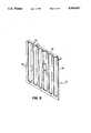
- FIG. 5is a perspective view of the expansion slot seal of the present invention.
- a personal computer central processing unit chassis constructed in accordance with the prior artis generally identified by the reference numeral 10.
- the chassis 10comprises a base 12 and a cover 14.
- the base 12comprises a metallic frame having a front panel 16 and a rear panel 18.
- the base 12holds electronic components, such as a microprocessor, a disk drive (neither shown) and circuit cards 20 which are installed on the base 12 by card holders 22.
- the cover 14is positioned over the base 12 to form an enclosed container.
- expansion slots 24are used to interconnect circuit cards (such as the card 20) with peripheral components such as a printer, a keyboard or a monitor.
- radio frequencyDue to the electronic components within the chassis 10, high frequencies are generated, causing radio frequency to be emitted.
- the radio frequencymay escape the chassis 10 through any openings therein. Openings such as expansion slots 24 are an obvious escape route for radio frequency.
- each slot 24is typically covered by a slot cover 26.
- a slot cover 26Unfortunately, due to the mismatching of the surfaces between the slots 24 and the covers 26, an imperfect closure is formed allowing excessive amounts of RF to escape.
- FIGS. 2-5a partially exploded perspective view of an expansion slot assembly and seal constructed in accordance with the preferred embodiment of the present invention is illustrated.
- the expansion slots 24are formed by an expansion slot assembly 30.
- the expansion slot assembly 30comprises a plurality of elongate, generally rectangular first strips 32 and spaced apart second strips 34.
- the first and second strips 32-34may have a centrally located generally U-shaped groove 33 formed therein to help strengthen the strips.
- the slots 24are formed by the gap between the strips 32 and 34 with strips 32-34 forming edges thereof.
- the assembly 30is installed onto the rear panel 18 of a CPU by attaching flanges 35 by any appropriate method such as screws or welds (not shown) or rivets 36.
- the seal 37is disposed between the first and second strips 32-34 and the slot cover 26. With the addition of the seal 37, the emission of radio frequency through the slots 24 is greatly reduced.
- the seal 37comprises a relatively thin, resilient, metallic substance dimensioned to be secured over the slot assembly 30.
- the seal 37comprises a plurality of elongate, generally rectangular spaced apart strips 38.
- the strips 38are spaced apart to coincide with the first strips 32 and the second strips 34 of the slot assembly 30.
- the strips 38 of the seal 37are interconnected by a first connecting strip 42 and a second connecting strip 44.
- the first connecting strip 42is formed generally perpendicular to the spaced-apart strips 38 to allow connection to the slot assembly 30 through a hole 43 and a screw (not shown).
- seal 37from a non-corrosive, metallic substance such as, for example, stainless steel.
- the seal 37must be an electrical conductor and must have sufficient resiliency or springiness to allow temporary deformation when compressed into sealing contact with the slot assembly 30.
- Each strip 38 of the seal 37has a flat portion 46 and at least one angled portion 48.
- the flat portion 46is placed in contact with the first or second strips 32-34 of the slot assembly 30.
- the angled portion 48is preferably angled away from the surface of the strips 32-34 for contact with the slot cover 26.
- the slot cover 26comprises an elongate, generally rectangular, relatively stiff metallic strip 50.
- a connecting portion 52is formed at an angle to strip 50 to allow connection to the slot assembly 30 by any appropriate method, such as a screw 54 through a hole 56.
- a tapered portion 58is formed in distal connecting portion 52 to allow insertion into a retaining device, as will be subsequently described in greater detail.
- FIG. 3a top view along line 3--3 of FIG. 2 is illustrated.
- a first strip 32is spaced apart from a second strip 34 to form an expansion slot 24 therebetween.
- a generally U-Shaped groove 33is formed along the center of each strip 32-34 to provide added structural strength thereto.
- the seal 37is positioned over each strip 32-34 and held in place by the slot cover 26.
- the flat portion 46 of the seal 37is in intimate contact with the strips 32 or 34 while the angled portion 48 is in intimate contact with the cover 26.
- the angled portion 48is compressed to form a tight seal around the slot 24.
- FIG. 4a partial cross-sectional view along lines 4--4 of FIG. 2 is shown.
- the slot assembly 30is fixed to the rear panel 18 with a slot 24 positioned for future expansion.
- the slot cover 26is forced against the seal 37 by a retaining device 60.
- the retaining device 60comprises a support piece 62 and a spring steel retainer 64. When the tapered portion 58 of the cover 26 is inserted into the retaining device 60, the retainer 64 forces the cover 26 against the seal 37 and flattens the angled portion 48.
- the expansion slot seal 37is shown in perspective. As seen in FIG. 5, the seal 37 is a generally rectangular assembly with the first connecting strip 42 formed perpendicular to the strips 38. The strips 38 each have a central flat portion 46 with angled portions 48 extending therefrom. Holes 43 allow attachment of the seal 37 to an expansion slot assembly by screws.
- the slot assembly 30is installed onto the rear panel 18 of a CPU by any appropriate method, such as rivets 36.
- a slot seal 37is then placed over the slot assembly 30 by aligning the strips 38 with the first and second strips 32-34 which form the edges of the slots 24.
- a slot cover 26is then positioned over each slot 24 and secured in place with screw 54.
- the slot cover 26is forced into the seal 37, which is in-turn forced against the slot assembly 30.
- the angled portion 48 on the seal 37is pressed toward the slot assembly 30 and in conjunction with the flat portions 46, seals any spaces that may occur from normal mismatch of materials.
- the slot assembly 30is effectively sealed to inhibit the escape of radio frequency from the chassis 10.
Landscapes
- Engineering & Computer Science (AREA)
- Theoretical Computer Science (AREA)
- Physics & Mathematics (AREA)
- General Engineering & Computer Science (AREA)
- Computer Hardware Design (AREA)
- Power Engineering (AREA)
- Human Computer Interaction (AREA)
- General Physics & Mathematics (AREA)
- Microelectronics & Electronic Packaging (AREA)
- Electromagnetism (AREA)
- Casings For Electric Apparatus (AREA)
- Shielding Devices Or Components To Electric Or Magnetic Fields (AREA)
Abstract
Description
Claims (7)
Priority Applications (1)
| Application Number | Priority Date | Filing Date | Title |
|---|---|---|---|
| US07/356,689US5004867A (en) | 1988-11-14 | 1989-05-25 | Personal computer expansion slot seal and method |
Applications Claiming Priority (2)
| Application Number | Priority Date | Filing Date | Title |
|---|---|---|---|
| US07/270,266US4873395A (en) | 1988-11-14 | 1988-11-14 | Personal computer expansion slot seal and method |
| US07/356,689US5004867A (en) | 1988-11-14 | 1989-05-25 | Personal computer expansion slot seal and method |
Related Parent Applications (1)
| Application Number | Title | Priority Date | Filing Date |
|---|---|---|---|
| US07/270,266ContinuationUS4873395A (en) | 1988-11-14 | 1988-11-14 | Personal computer expansion slot seal and method |
Publications (1)
| Publication Number | Publication Date |
|---|---|
| US5004867Atrue US5004867A (en) | 1991-04-02 |
Family
ID=26954181
Family Applications (1)
| Application Number | Title | Priority Date | Filing Date |
|---|---|---|---|
| US07/356,689Expired - LifetimeUS5004867A (en) | 1988-11-14 | 1989-05-25 | Personal computer expansion slot seal and method |
Country Status (1)
| Country | Link |
|---|---|
| US (1) | US5004867A (en) |
Cited By (21)
| Publication number | Priority date | Publication date | Assignee | Title |
|---|---|---|---|---|
| US5406809A (en)* | 1991-05-13 | 1995-04-18 | Igelmund; Darrell A. | Mechanical security fixture for personal computers |
| US5430607A (en)* | 1992-12-31 | 1995-07-04 | North Atlantic Industries, Inc. | Rugged modular portable computer including modules hinged along an edge |
| US5575546A (en)* | 1995-07-21 | 1996-11-19 | Dell U.S.A., L.P. | Apparatus for retention of computer expansion cards and filler panels |
| US5579210A (en)* | 1995-05-05 | 1996-11-26 | At&T Global Information Solutions Company | Apparatus and method for covering interface openings in a computer housing |
| US5640309A (en)* | 1996-07-01 | 1997-06-17 | Sun Microsystems, Inc. | PCI expansion card retainer clip |
| US5650922A (en)* | 1996-04-16 | 1997-07-22 | Ho; Hsin Chien | Computer interface card mounting structure |
| US5822195A (en)* | 1997-03-31 | 1998-10-13 | Digital Equipment Corporation | Interface that permits data bus signals to pass between high frequency processing unit and low frequency expansion devices |
| EP0806720A3 (en)* | 1996-05-10 | 1999-03-17 | Siemens Nixdorf Informationssysteme AG | Support for a circuit in equipment |
| US5967466A (en)* | 1998-09-04 | 1999-10-19 | Unitrend, Inc. | Back plane lock down |
| US6018464A (en)* | 1997-03-10 | 2000-01-25 | Samsung Electronics Co., Ltd. | Option card-equipping device for improving electromagnetic shielding and a computer using the same |
| US6058025A (en)* | 1998-04-21 | 2000-05-02 | International Business Machines Corporation | Computer tailgate having expansion slot alignment pins |
| USRE36695E (en)* | 1995-07-25 | 2000-05-16 | Dell U.S.A., L.P. | Captive latch mechanism for use with an expansion card cage in a personal computer |
| US6147874A (en)* | 1998-12-18 | 2000-11-14 | 3Com Corporation | Backplate for securing printed circuit card to a computer chassis |
| US6295208B1 (en) | 1999-02-12 | 2001-09-25 | 3Com Corporation | Backplate for securing a circuit card to a computer chassis |
| US6346009B1 (en) | 1998-11-11 | 2002-02-12 | Molex Incorporated | Shielded multiple electrical connector assembly |
| US6462959B1 (en)* | 2001-12-28 | 2002-10-08 | Enlight Corporation | Interface card and interface cardholder mounting arrangement |
| US6499198B2 (en)* | 2000-06-07 | 2002-12-31 | Trans Technology Engineered Componenets, Llc | Retaining clip for computer expansion card |
| US6662609B1 (en)* | 1999-08-20 | 2003-12-16 | Gateway, Inc. | Sequentially unlocking expansion slots |
| US20100020550A1 (en)* | 2008-07-28 | 2010-01-28 | Panasonic Electric Works Co., Ltd. | Illumination device including a detachable sensor |
| US20110156552A1 (en)* | 2009-12-24 | 2011-06-30 | Hong Fu Jin Precision Industry (Shenzhen) Co., Ltd. | Computer case |
| US20240028083A1 (en)* | 2022-07-19 | 2024-01-25 | Hewlett-Packard Development Company, L.P. | Brackets for mounting electronic components |
Citations (3)
| Publication number | Priority date | Publication date | Assignee | Title |
|---|---|---|---|---|
| US1765443A (en)* | 1928-02-25 | 1930-06-24 | Rca Corp | Shielding |
| US3277230A (en)* | 1965-03-17 | 1966-10-04 | Instr Specialties Co Inc | Shielding gaskets with fastening means |
| US4744006A (en)* | 1986-07-10 | 1988-05-10 | Duffield Robert H | Apparatus for expanding the input/output capabilities of a personal computer |
- 1989
- 1989-05-25USUS07/356,689patent/US5004867A/ennot_activeExpired - Lifetime
Patent Citations (3)
| Publication number | Priority date | Publication date | Assignee | Title |
|---|---|---|---|---|
| US1765443A (en)* | 1928-02-25 | 1930-06-24 | Rca Corp | Shielding |
| US3277230A (en)* | 1965-03-17 | 1966-10-04 | Instr Specialties Co Inc | Shielding gaskets with fastening means |
| US4744006A (en)* | 1986-07-10 | 1988-05-10 | Duffield Robert H | Apparatus for expanding the input/output capabilities of a personal computer |
Cited By (23)
| Publication number | Priority date | Publication date | Assignee | Title |
|---|---|---|---|---|
| US5406809A (en)* | 1991-05-13 | 1995-04-18 | Igelmund; Darrell A. | Mechanical security fixture for personal computers |
| US5430607A (en)* | 1992-12-31 | 1995-07-04 | North Atlantic Industries, Inc. | Rugged modular portable computer including modules hinged along an edge |
| US5579210A (en)* | 1995-05-05 | 1996-11-26 | At&T Global Information Solutions Company | Apparatus and method for covering interface openings in a computer housing |
| US5575546A (en)* | 1995-07-21 | 1996-11-19 | Dell U.S.A., L.P. | Apparatus for retention of computer expansion cards and filler panels |
| USRE36695E (en)* | 1995-07-25 | 2000-05-16 | Dell U.S.A., L.P. | Captive latch mechanism for use with an expansion card cage in a personal computer |
| US5650922A (en)* | 1996-04-16 | 1997-07-22 | Ho; Hsin Chien | Computer interface card mounting structure |
| EP0806720A3 (en)* | 1996-05-10 | 1999-03-17 | Siemens Nixdorf Informationssysteme AG | Support for a circuit in equipment |
| US5640309A (en)* | 1996-07-01 | 1997-06-17 | Sun Microsystems, Inc. | PCI expansion card retainer clip |
| US6018464A (en)* | 1997-03-10 | 2000-01-25 | Samsung Electronics Co., Ltd. | Option card-equipping device for improving electromagnetic shielding and a computer using the same |
| US5822195A (en)* | 1997-03-31 | 1998-10-13 | Digital Equipment Corporation | Interface that permits data bus signals to pass between high frequency processing unit and low frequency expansion devices |
| US6058025A (en)* | 1998-04-21 | 2000-05-02 | International Business Machines Corporation | Computer tailgate having expansion slot alignment pins |
| US5967466A (en)* | 1998-09-04 | 1999-10-19 | Unitrend, Inc. | Back plane lock down |
| US6346009B1 (en) | 1998-11-11 | 2002-02-12 | Molex Incorporated | Shielded multiple electrical connector assembly |
| US6147874A (en)* | 1998-12-18 | 2000-11-14 | 3Com Corporation | Backplate for securing printed circuit card to a computer chassis |
| US6295208B1 (en) | 1999-02-12 | 2001-09-25 | 3Com Corporation | Backplate for securing a circuit card to a computer chassis |
| US6662609B1 (en)* | 1999-08-20 | 2003-12-16 | Gateway, Inc. | Sequentially unlocking expansion slots |
| US6666055B2 (en)* | 1999-08-20 | 2003-12-23 | Gateway, Inc. | Sequentially unlocking expansion slots |
| US6499198B2 (en)* | 2000-06-07 | 2002-12-31 | Trans Technology Engineered Componenets, Llc | Retaining clip for computer expansion card |
| US6462959B1 (en)* | 2001-12-28 | 2002-10-08 | Enlight Corporation | Interface card and interface cardholder mounting arrangement |
| US20100020550A1 (en)* | 2008-07-28 | 2010-01-28 | Panasonic Electric Works Co., Ltd. | Illumination device including a detachable sensor |
| US8167453B2 (en)* | 2008-07-28 | 2012-05-01 | Panasonic Corporation | Illumination device including interchangeable sensor and decoration members |
| US20110156552A1 (en)* | 2009-12-24 | 2011-06-30 | Hong Fu Jin Precision Industry (Shenzhen) Co., Ltd. | Computer case |
| US20240028083A1 (en)* | 2022-07-19 | 2024-01-25 | Hewlett-Packard Development Company, L.P. | Brackets for mounting electronic components |
Similar Documents
| Publication | Publication Date | Title |
|---|---|---|
| US5004867A (en) | Personal computer expansion slot seal and method | |
| US4873395A (en) | Personal computer expansion slot seal and method | |
| US5959244A (en) | Front and rear contacting EMI gasket | |
| US6058025A (en) | Computer tailgate having expansion slot alignment pins | |
| US5335147A (en) | EMI shield apparatus and methods | |
| US5323299A (en) | EMI internal shield apparatus and methods | |
| EP0852899B1 (en) | Gasket system for emi isolation | |
| EP0425193B1 (en) | Electromagnetic interference shield apparatus | |
| US20030081398A1 (en) | Removable EMI cover for a media drive housing | |
| US7170013B2 (en) | Spring fingers with end extensions | |
| JP2000347767A (en) | Computer system housing | |
| US6309037B2 (en) | PCI I/O bracket retainer | |
| US20030160396A1 (en) | Snap-on EMI gasket clip and method of sealing a computer chassis from EMI | |
| JPH0267000A (en) | Radio frequency disturbance shielding device | |
| US5770822A (en) | Bulkhead gasket assembly | |
| US7327584B2 (en) | Electromagnetic radiation containment system | |
| US4916578A (en) | Personal computer chassis connection and method | |
| US6444900B1 (en) | Electromagnetic interference shielding gasket | |
| US6822877B2 (en) | EMC shield for expansion slots | |
| US6870093B2 (en) | Adaptable EMI/RFI shielding for a front-panel attachment to an enclosure | |
| US5365285A (en) | CRT display device with a grounded rimband so as to suppress an electro-magnetic emission | |
| KR100286396B1 (en) | Shielded module support structure | |
| US6508653B2 (en) | Computer system bulkhead plate for attenuating electromagnetic interference (EMI) at a telephone jack connector | |
| US5686695A (en) | Resilient plate for a computer interface card | |
| US7671283B2 (en) | Apparatus for shielding electromagnetic radiation |
Legal Events
| Date | Code | Title | Description |
|---|---|---|---|
| AS | Assignment | Owner name:COMPUADD CORPORATION, A CORP. OF TX Free format text:CHANGE OF NAME;ASSIGNOR:COMPUADD, INC. (CHANGED TO);REEL/FRAME:005159/0752 Effective date:19890123 | |
| FEPP | Fee payment procedure | Free format text:PAYOR NUMBER ASSIGNED (ORIGINAL EVENT CODE: ASPN); ENTITY STATUS OF PATENT OWNER: LARGE ENTITY | |
| STCF | Information on status: patent grant | Free format text:PATENTED CASE | |
| AS | Assignment | Owner name:FIRST INTERSTATE BANK OF TEXAS, N.A., TEXAS Free format text:ASSIGNMENT OF ASSIGNORS INTEREST.;ASSIGNOR:COMPUADD CORPORATION;REEL/FRAME:006280/0660 Effective date:19921003 | |
| AS | Assignment | Owner name:FIRST INTERSTATE BANK OF TEXAS, N.A., AS AGENT, TE Free format text:SECURITY INTEREST;ASSIGNOR:COMPUADD CORPORATION, A TEXAS CORP.;REEL/FRAME:006807/0476 Effective date:19931115 | |
| AS | Assignment | Owner name:AT&T COMMERCIAL FINANCE CORPORATION, A DELAWARE CO Free format text:SECURITY INTEREST;ASSIGNOR:COMPUADD CORPORATION, A TEXAS CORPORATION;REEL/FRAME:006827/0913 Effective date:19931115 | |
| FPAY | Fee payment | Year of fee payment:4 | |
| AS | Assignment | Owner name:COMPUADD CORPORATION, TEXAS Free format text:RELEASE OF SECURITY INTEREST AND LIEN AFFECTING TITLE TO ISSUED U.S. PATENTS AND PENDING U.S. PATENT APPLICATIONS;ASSIGNOR:AT&T COMMERCIAL FINANCE CORPORATION;REEL/FRAME:007764/0751 Effective date:19951212 Owner name:COMPUADD, TEXAS Free format text:RELEASE OF SECURITY INTEREST AND LIEN AFFECTING TITLE TO ISSUED U.S. PATENTS AND PENDING U.S. PATENT APPLICATIONS;ASSIGNOR:FIRST INTERSTATE BANK OF TEXAS, N.A.;REEL/FRAME:007764/0576 Effective date:19951213 Owner name:GATEWAY 2000, SOUTH DAKOTA Free format text:ASSIGNMENT OF ASSIGNORS INTEREST;ASSIGNOR:COMPUADD CORPORATION;REEL/FRAME:007764/0567 Effective date:19951213 | |
| FEPP | Fee payment procedure | Free format text:PAYER NUMBER DE-ASSIGNED (ORIGINAL EVENT CODE: RMPN); ENTITY STATUS OF PATENT OWNER: LARGE ENTITY Free format text:PAYOR NUMBER ASSIGNED (ORIGINAL EVENT CODE: ASPN); ENTITY STATUS OF PATENT OWNER: LARGE ENTITY | |
| FEPP | Fee payment procedure | Free format text:PAYER NUMBER DE-ASSIGNED (ORIGINAL EVENT CODE: RMPN); ENTITY STATUS OF PATENT OWNER: LARGE ENTITY | |
| FPAY | Fee payment | Year of fee payment:8 | |
| SULP | Surcharge for late payment | ||
| FEPP | Fee payment procedure | Free format text:PAYOR NUMBER ASSIGNED (ORIGINAL EVENT CODE: ASPN); ENTITY STATUS OF PATENT OWNER: LARGE ENTITY | |
| FPAY | Fee payment | Year of fee payment:12 |