US5004632A - Fire resistant tank construction - Google Patents
Fire resistant tank constructionDownload PDFInfo
- Publication number
- US5004632A US5004632AUS07/491,272US49127290AUS5004632AUS 5004632 AUS5004632 AUS 5004632AUS 49127290 AUS49127290 AUS 49127290AUS 5004632 AUS5004632 AUS 5004632A
- Authority
- US
- United States
- Prior art keywords
- tank
- fire resistant
- walls
- inch
- resistant material
- Prior art date
- Legal status (The legal status is an assumption and is not a legal conclusion. Google has not performed a legal analysis and makes no representation as to the accuracy of the status listed.)
- Expired - Lifetime
Links
- 230000009970fire resistant effectEffects0.000titleclaimsabstractdescription29
- 238000010276constructionMethods0.000titledescription5
- 239000007788liquidSubstances0.000claimsabstractdescription17
- 229930195733hydrocarbonNatural products0.000claimsabstractdescription14
- 150000002430hydrocarbonsChemical class0.000claimsabstractdescription14
- 238000009434installationMethods0.000claimsabstractdescription14
- 239000004215Carbon black (E152)Substances0.000claimsabstractdescription11
- 239000011248coating agentSubstances0.000claimsabstractdescription8
- 238000000576coating methodMethods0.000claimsabstractdescription8
- 239000000463materialSubstances0.000claimsdescription44
- 238000000034methodMethods0.000claimsdescription17
- 238000011065in-situ storageMethods0.000claimsdescription9
- 238000005507sprayingMethods0.000claimsdescription9
- 239000003822epoxy resinSubstances0.000claimsdescription5
- 229920000647polyepoxidePolymers0.000claimsdescription5
- -1curedSubstances0.000claimsdescription2
- 239000007921spraySubstances0.000claimsdescription2
- 230000014759maintenance of locationEffects0.000claims2
- 230000000593degrading effectEffects0.000claims1
- 238000005488sandblastingMethods0.000claims1
- 239000007787solidSubstances0.000claims1
- 229920003002synthetic resinPolymers0.000claims1
- 239000000057synthetic resinSubstances0.000claims1
- 239000012260resinous materialSubstances0.000abstractdescription2
- 239000010410layerSubstances0.000description11
- 238000004079fireproofingMethods0.000description10
- YMWUJEATGCHHMB-UHFFFAOYSA-NDichloromethaneChemical compoundClCClYMWUJEATGCHHMB-UHFFFAOYSA-N0.000description6
- IJGRMHOSHXDMSA-UHFFFAOYSA-NAtomic nitrogenChemical compoundN#NIJGRMHOSHXDMSA-UHFFFAOYSA-N0.000description2
- 101000623895Bos taurus Mucin-15Proteins0.000description2
- 239000004593EpoxySubstances0.000description2
- 229910000831SteelInorganic materials0.000description2
- 239000002131composite materialSubstances0.000description2
- 238000005336crackingMethods0.000description2
- 230000000694effectsEffects0.000description2
- 239000012530fluidSubstances0.000description2
- 239000000446fuelSubstances0.000description2
- 239000007789gasSubstances0.000description2
- 239000002184metalSubstances0.000description2
- 229910052751metalInorganic materials0.000description2
- 239000004848polyfunctional curativeSubstances0.000description2
- 239000011347resinSubstances0.000description2
- 229920005989resinPolymers0.000description2
- 239000010959steelSubstances0.000description2
- 239000004952PolyamideSubstances0.000description1
- 101100386054Saccharomyces cerevisiae (strain ATCC 204508 / S288c) CYS3 geneProteins0.000description1
- 229920006328StyrofoamPolymers0.000description1
- BOTDANWDWHJENH-UHFFFAOYSA-NTetraethyl orthosilicateChemical compoundCCO[Si](OCC)(OCC)OCCBOTDANWDWHJENH-UHFFFAOYSA-N0.000description1
- HCHKCACWOHOZIP-UHFFFAOYSA-NZincChemical compound[Zn]HCHKCACWOHOZIP-UHFFFAOYSA-N0.000description1
- 238000009825accumulationMethods0.000description1
- 230000001464adherent effectEffects0.000description1
- QVGXLLKOCUKJST-UHFFFAOYSA-Natomic oxygenChemical compound[O]QVGXLLKOCUKJST-UHFFFAOYSA-N0.000description1
- 230000015572biosynthetic processEffects0.000description1
- 238000007707calorimetryMethods0.000description1
- 238000004140cleaningMethods0.000description1
- 239000011247coating layerSubstances0.000description1
- 230000009977dual effectEffects0.000description1
- 230000002708enhancing effectEffects0.000description1
- 230000009969flowable effectEffects0.000description1
- JEIPFZHSYJVQDO-UHFFFAOYSA-Niron(III) oxideInorganic materialsO=[Fe]O[Fe]=OJEIPFZHSYJVQDO-UHFFFAOYSA-N0.000description1
- 238000012806monitoring deviceMethods0.000description1
- 229910052757nitrogenInorganic materials0.000description1
- 239000001301oxygenSubstances0.000description1
- 229910052760oxygenInorganic materials0.000description1
- 230000035699permeabilityEffects0.000description1
- 230000000704physical effectEffects0.000description1
- 229920002647polyamidePolymers0.000description1
- 230000001681protective effectEffects0.000description1
- 238000007665saggingMethods0.000description1
- 239000004576sandSubstances0.000description1
- 125000006850spacer groupChemical group0.000description1
- 101150035983str1 geneProteins0.000description1
- 238000005728strengtheningMethods0.000description1
- 239000008261styrofoamSubstances0.000description1
- 238000002834transmittanceMethods0.000description1
- 229910052902vermiculiteInorganic materials0.000description1
- 235000019354vermiculiteNutrition0.000description1
- 239000010455vermiculiteSubstances0.000description1
- XLYOFNOQVPJJNP-UHFFFAOYSA-NwaterChemical compoundOXLYOFNOQVPJJNP-UHFFFAOYSA-N0.000description1
- 230000003313weakening effectEffects0.000description1
- 229910052725zincInorganic materials0.000description1
- 239000011701zincSubstances0.000description1
Images

Classifications
- B—PERFORMING OPERATIONS; TRANSPORTING
- B05—SPRAYING OR ATOMISING IN GENERAL; APPLYING FLUENT MATERIALS TO SURFACES, IN GENERAL
- B05D—PROCESSES FOR APPLYING FLUENT MATERIALS TO SURFACES, IN GENERAL
- B05D7/00—Processes, other than flocking, specially adapted for applying liquids or other fluent materials to particular surfaces or for applying particular liquids or other fluent materials
- B05D7/14—Processes, other than flocking, specially adapted for applying liquids or other fluent materials to particular surfaces or for applying particular liquids or other fluent materials to metal, e.g. car bodies
- B05D7/16—Processes, other than flocking, specially adapted for applying liquids or other fluent materials to particular surfaces or for applying particular liquids or other fluent materials to metal, e.g. car bodies using synthetic lacquers or varnishes
- B—PERFORMING OPERATIONS; TRANSPORTING
- B65—CONVEYING; PACKING; STORING; HANDLING THIN OR FILAMENTARY MATERIAL
- B65D—CONTAINERS FOR STORAGE OR TRANSPORT OF ARTICLES OR MATERIALS, e.g. BAGS, BARRELS, BOTTLES, BOXES, CANS, CARTONS, CRATES, DRUMS, JARS, TANKS, HOPPERS, FORWARDING CONTAINERS; ACCESSORIES, CLOSURES, OR FITTINGS THEREFOR; PACKAGING ELEMENTS; PACKAGES
- B65D90/00—Component parts, details or accessories for large containers
- B65D90/48—Arrangements of indicating or measuring devices
- B65D90/50—Arrangements of indicating or measuring devices of leakage-indicating devices
- B65D90/501—Arrangements of indicating or measuring devices of leakage-indicating devices comprising hollow spaces within walls
Definitions
- This inventionrelates generally to tanks for flammable and combustible liquids, and more particularly concerns methods and means for making such tanks fire resistant in above-ground installation environments.
- Tanks holding flammable or combustible liquidscan be dangerous if not "fireproofed", i.e., made “fire resistant". For example, if the tanks leak flammable liquid, a fire danger will exist. Fire can weaken the lightweight tank walls and lead to tank collapse and spillage of tank contents.
- the method of providing a fire resistant tank apparatus, for flammable liquidincludes the steps:
- the application stepis typically carried out by spraying said material:
- the sprayable and hardenable fire resistant materialtypically has an epoxide resin base, and chars when exposed to flame.
- a sprayable two component intumescent epoxy fireproofing system(liquid resin and hardener, mixed with methylene chloride, or 1,1,1,-trichloroethane) supplied by Avco Specialty Materials, Lowell, Mass.
- a further safety featureis the construction of the tank walls themselves to have inner and outer sub-walls defining a gap therebetween, and including means to sense hydrocarbon vapor in the gap. Thus, leakage may be detected prior to access of leaking fluid to the protective shell.
- the fire resistant tank apparatus(to hold and dispense flammable liquid such as hydrocarbon fuel, or the like) comprises:
- the shellhaving thickness between about 1/4 inch and 1 inch.
- the shelltypically comprises:
- tank wallsmay include inner and outer sub-walls defining a gap therebetween, and means may be provided to sense hydrocarbon vapor in the gap. Also, fireproofing material may be employed in the gap.
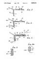
- FIG. 1is a perspective view of a metallic tank, prior to spraying of fire resistant material onto the tank walls;
- FIG. 2is a fragmentary section showing spray-on of fireproof coating material
- FIG. 3is a view like FIG. 2, but showing spray-on of multiple layers of the fireproof coating material
- FIG. 4is a view like FIG. 2, but showing a multi-wall tank construction
- FIG. 5is a fragmentary section showing use of mesh embedded in the sprayed on fireproofing material
- FIG. 5ais a fragmentary section showing a filled gap between a double wall tank structure
- FIG. 6is a side elevation showing the fireproofed tank supported in a shallow receptacle at an installation site
- FIG. 7is an end view of a tank, showing support means being sprayed with fire-resistant material.
- a tank 10 to be made fire resistantincludes upright front and rear side walls 11 and 12, upright end walls 13 and 14, and horizontal top and bottom walls 15 and 15a.
- Such wallsmay consist of steel and be less than one inch thick, for lightweight tank construction enhancing portability, for installation above ground at different sites, as desired.
- the steel wallsabout 10 gauge (1/8 to 1/4 inch thick).
- the tank length between walls 13 and 14may typically be about 10-15 feet.
- the wallsare typically interconnected by welds at their junctions, as at 16-19, 20-23, and 24-27.
- Internal bracesmay be provided, as at 28-29, and vertical braces at 28a and 29a.
- the tank side wallsmay define a cylindrical tank, which may be considered to have side and end walls integrated into a cylindrical wall.
- bungs 30 and 31which are removable from upright stub pipes 32 and 33, respectively.
- a pipe cover 34is rearwardly attached to the top of the stub pipe 35; and a vent cover 36 is attached to stub pipe 37.
- the upright stub pipes(providing means to define access porting to the tank interior) are welded to the top wall and provide access to the tank interior via ports in the top wall. Dipsticks (as at 34a) may thus be inserted into the tank to measure the level of liquid hydrocarbon, i.e., flammable or combustible liquid (such as fuel) in the tank.
- Monitor means 39may be installed in the tank via one of the access ports to sense liquid level and transmit corresponding electrical signals to external apparatus 40 that registers the liquid level for ready viewing.
- FIG. 2it shows a nozzle 42 spraying fire resistant synthetic resinous material at 43 onto the tank walls, to a thickness between about 1/4 inch and 1 inch
- That materialwhich may typically be epoxide resin based, is allowed to harden in situ, to form a relatively lightweight shell 50 enclosing and adhering to the metallic tank, on all sides, ends, and top and bottom
- the materialis sprayed closely adjacent, and typically onto and about the stub pipe, as at 51, i.e., adherent to pipe 32, at the top wall, and is also sprayed closely adjacent (i.e. onto and about the sides of) support means such as the supports 52 integral with the bottom wall. See shell layers 53 and 54 on the sides of supports 52, in FIG. 7.
- the material forming shell 50may be otherwise applied to the tank wall or walls; however, spraying is preferred as it allows troweling of the material, for finishing.
- the shell thicknessis greater than about 1 inch, the total unit weight becomes too great for ease of transport; and if the shell thickness is less than about 1/4 inch, the desired "fireproofing" is reduced to an unacceptable level--i.e., fireproofing effect becomes too small.
- the material 43 being sprayed onmay cling to, the upright metal walls without sagging out of position, and also to have optimum fireproofing effect, it has typically an epoxide resin base, and chars when exposed to flame.
- a sprayable two component intumescent epoxy fireproofing system(liquid resin and hardener, mixed with methylene chloride, or 1,1,1,-trichloroethane) supplied by Avco Specialty Materials, Lowell, Mass.
- FIG. 3shows a nozzle 42 spraying fireproofing material at 43 onto the tank wall 11 to form a first layer 50a, which is allowed to harden or cure, in situ; and a second nozzle 42a (or the same nozzle 42) is then used to spray fireproofing material 43a onto the layer 50a, to form a second layer 50b, which is allowed to harden, in situ.
- the combination of shells or layers 50a and 50bform the composite shell 50 having thickness between 1/4 and 1 inch. Dual shells as defined, or even more shells in the composite, provide an even stronger, more leak resistant and fire resistant unit.
- An interface between the sub-shells 50a and 50bappears at 56 and each applied coat is troweled before application of the next coat.
- the primer coatmay, for example, consist of polyamide epoxy resin, such as AMERON 71, SUBOX A8051, or VAL-CHEM 13-R-56, or ethyl silicate inorganic zinc (such as DIMETCOTE 6).
- FIG. 4shows a tank consisting of outer tank walls 11-16 as referred to above, and inner metallic walls 11a-16a, as shown. Walls 11a-16a are spaced from the respective walls 11-16, as by local spacers 60, to provide a gap or space 61 between the walls. Any fluid leaking from the tank interior via the inner walls passes first to the gap 61, and may be detected as by a sensor 63 sensing volatile gases emitted by the flammable hydrocarbon The sensor or detector is connected at 64 to an external monitoring device 65, as shown. Flow of air or flammable liquid in the gap may be induced, as by a blower 66.
- FIG. 5shows a strengthening mesh 67, for example made of wire, embedded in the shell 50 forward about the tank walls.
- FIG. 5ashows the tank wall means (side wall or walls an/or top wall and/or bottom wall, as referred to) to include for example inner and outer sub-walls 111 and 111a.
- a gap between the sub-wallscontains fire resistant material 150 (as for example of the type described above) to effectively define a shell including the inner sub-wall 111, the shell thickness between 1/4 inch and 1 inch.
- the shellmay otherwise consist of an insulative sheet such as styrofoam or flowable fireproof material, such as VERMICULITE.
- Broken lines 115 and 116show extensions of such structure to the top and bottom wall construction of the tank.
- FIG. 6shows a fireproof material coated tank, stub pipes, and supports, installed at a work site, in a basin 70 supported on the ground 71.
- the basinforms a collection zone 73 beneath the tank to collect any possible leakage of flammable liquid.
- a hood 76may be provided over the tank and basin to prevent rainwater accumulation in the basin.
Landscapes
- Engineering & Computer Science (AREA)
- Life Sciences & Earth Sciences (AREA)
- Wood Science & Technology (AREA)
- Mechanical Engineering (AREA)
- Filling Or Discharging Of Gas Storage Vessels (AREA)
- Application Of Or Painting With Fluid Materials (AREA)
Abstract
Description
TABLE 1 ______________________________________ CHARTEK MECHANICAL PROPERTIES ASTM Property Reference Value Conditions ______________________________________ Tensile Strength D638 2750 psi Room Temp. 19.0 × 10.sup.6 PA Modulus 3.42 × 10.sup.5 psi Room Temp. 2.36 × 10.sup.9 PA Compressive D659 6342 psi Room Temp. Strength 43.7 × 10.sup.6 PA Modulus 1.89 × 10.sup.5 psi Room Temp. 1.3 × 10.sup.9 PA Impact Strength D256 0.42 ft lbs/in Room Temp. (unsupported, 0.22 J/cm notched unmeshed) 0.71 ft lbs/in Room Temp. 0.38 J/cm unnotched Flexural Strength D790 4290 psi Room Temp. 29.6 × 10.sup.6 PA Modulus 3.32 × 10.sup.5 psi Room Temp. 2.3 × 10.sup.9 PA Hardness Shore D 83 D Scale Bond Strength D1002 1578 psi Primed, 10.9 × 10.sup.9 PA room temp. ______________________________________
TABLE II __________________________________________________________________________PHYSICAL PROPERTIES ASTM Property Reference Value Conditions __________________________________________________________________________Density D792 79 lbs/ft.sup.3 After 1.27 g/cc spraying Thermal C177 2.10 BTU in/ft.sup.2 hr °F. At 68° F. Conductivity 0.302 W/m °C. At 20° C. 1.96 BTU in/ft.sup.2 hr °F. At 154° F. 0.283 W/m °C. At 68° C. Thermal Expansion D696 20.5 × 10.sup.-6 in/in °F. From -70° F. With Mesh 36.9 × 10.sup.-6 cm/cm °C. (-57° C.) to Thermal Expansion 36.4 × 10.sup.-6 in/in °F. 150° F. Without Mesh 65.5 × 10.sup.-6 cm/cm °C. (66° C.) Specific Heat Differential 0.33 BTU/lbm °F. At 86° F. Scanning 1.38 J/Kg °C. At 30° C. Calorimetry 0.23 BTU/lbm °F. At 500° F. 0.96 J/kg °C. At 260° C. Oxygen D2836 32 Index Flash Point D92 Component I Over 200° F. (93° C.) Open cup Component II Over 200° F. (93° C.) Open cup Viscosity Component I 285000 CPS At 100° F. (37.8° C.) Component II 60000 CPS At 100° F. (37.8° C.) Gas (Nitrogen) Permeability D1434 ##STR1## At 68° F., 1.51 Atm ##STR2## At 20° C., 1.53 Bar Water Vapor E96 1.013 × 10.sup.-3 gr/hr ft.sup.2 At 73° F. (22.8° C.) Transmittance Procedure 4.07 × 10.sup.-1 g/hr m.sup.2 and 50% RH B Pot Life 55 minutes At 70° F. (21° C.) Gel Time 8 hours At 60° F. (16° C.) 4 hours At 80° F. (27° C.) Cure Time to 18 hours At 60° F. Shore A of 85 (16° C.) 8 hours At 80° F. (27° C.) Color Grey Maximum Service 150° F. Continuous Temperature (66° C.) Use __________________________________________________________________________
Claims (12)
Priority Applications (1)
| Application Number | Priority Date | Filing Date | Title |
|---|---|---|---|
| US07/491,272US5004632A (en) | 1988-03-31 | 1990-03-09 | Fire resistant tank construction |
Applications Claiming Priority (2)
| Application Number | Priority Date | Filing Date | Title |
|---|---|---|---|
| US33154888A | 1988-03-31 | 1988-03-31 | |
| US07/491,272US5004632A (en) | 1988-03-31 | 1990-03-09 | Fire resistant tank construction |
Related Parent Applications (1)
| Application Number | Title | Priority Date | Filing Date |
|---|---|---|---|
| US33154888ADivision | 1988-03-31 | 1988-03-31 |
Publications (1)
| Publication Number | Publication Date |
|---|---|
| US5004632Atrue US5004632A (en) | 1991-04-02 |
Family
ID=26987814
Family Applications (1)
| Application Number | Title | Priority Date | Filing Date |
|---|---|---|---|
| US07/491,272Expired - LifetimeUS5004632A (en) | 1988-03-31 | 1990-03-09 | Fire resistant tank construction |
Country Status (1)
| Country | Link |
|---|---|
| US (1) | US5004632A (en) |
Cited By (16)
| Publication number | Priority date | Publication date | Assignee | Title |
|---|---|---|---|---|
| US5285920A (en)* | 1989-03-31 | 1994-02-15 | Lrs, Inc. | Fire resistant tank assembly and liquid hydrocarbon dispensing |
| US5487946A (en)* | 1994-08-02 | 1996-01-30 | Battelle Memorial Institute | Thermally-protective intumescent coating |
| US5533648A (en)* | 1994-01-10 | 1996-07-09 | Novus International, Inc. | Portable storage and dispensing system |
| US5570714A (en)* | 1993-03-18 | 1996-11-05 | Liquid Management Products, Inc. | Explosion-retardant containment vessel for storage of flammable liquids |
| US5601204A (en)* | 1989-12-19 | 1997-02-11 | Hall; William Y. | Tank vault with sealed liner |
| US5989706A (en)* | 1998-09-30 | 1999-11-23 | Battelle Memorial Institute | Thermally-protective intumescent coating system and method |
| US6026975A (en)* | 1998-12-17 | 2000-02-22 | Slater; Electus P. | Above ground storage tank for holding combustible material and supporting equipment thereon |
| US6257437B1 (en) | 1998-12-17 | 2001-07-10 | Electus P. Slater | Above ground storage tank for holding combustible material and supporting equipment thereon |
| US6286707B1 (en)* | 1989-12-19 | 2001-09-11 | William Y. Hall | Container for above-ground storage |
| US6289642B1 (en)* | 1999-07-29 | 2001-09-18 | Aranar, Inc. | Method and window structure in buildings for protecting glass panes during storms |
| US6422413B1 (en) | 1989-12-19 | 2002-07-23 | William Y. Hall | Tank vault |
| US20050076587A1 (en)* | 2001-08-03 | 2005-04-14 | Diamond Jeffrey H. | Method of removing one or more shards from the track of a frame |
| US6898907B2 (en) | 2001-06-12 | 2005-05-31 | Aranar, Inc. | Structures, window protection systems and methods for protecting glass panes during storms |
| US20070000194A1 (en)* | 2001-08-03 | 2007-01-04 | Diamond Jeffrey H | Stabilized window structures and methods for stabilizing and removing shattered window panes |
| WO2013101283A1 (en)* | 2011-04-12 | 2013-07-04 | Conocophillips Company | Cold box design providing secondary containment |
| US20220024674A1 (en)* | 2020-07-23 | 2022-01-27 | Cellblock Fcs, Llc | Shipping package for lithium battery |
Citations (25)
| Publication number | Priority date | Publication date | Assignee | Title |
|---|---|---|---|---|
| US810237A (en)* | 1905-05-06 | 1906-01-16 | William B Wadsworth | Means for controlling the level of liquids. |
| US1114019A (en)* | 1911-09-09 | 1914-10-20 | Sf Bowser & Co Inc | Automatic valve. |
| US1273195A (en)* | 1917-07-17 | 1918-07-23 | Harrison B Snyder | Fluid-control apparatus. |
| US1625765A (en)* | 1926-05-10 | 1927-04-19 | Cresco Creamery Supply Co | Valved outlet for pasteurizers |
| US1724582A (en)* | 1927-12-31 | 1929-08-13 | William E Hart | Liquid-fuel-elevating device for motor vehicles |
| US2460054A (en)* | 1945-11-26 | 1949-01-25 | John H Wiggins | Tank bottoms equipped with improved means for testing seams and recovering leakage from same |
| US2558694A (en)* | 1949-08-26 | 1951-06-26 | Karl M Speig | Storage tank |
| US2772834A (en)* | 1952-10-22 | 1956-12-04 | Otto Wanek | Steam turbine operated centrifugal pump mechanisms |
| US2864527A (en)* | 1956-12-10 | 1958-12-16 | Herrick L Johnston Inc | Container for liquefied gas |
| US2869751A (en)* | 1954-09-03 | 1959-01-20 | Pfauder Permutit Inc | Insulated storage tank and method of making a storage tank |
| US2931211A (en)* | 1953-11-18 | 1960-04-05 | Babcock & Wilcox Co | Storage tank exposure protection covering |
| US3595424A (en)* | 1969-02-24 | 1971-07-27 | Conch Int Methane Ltd | Containers for liquefied gases |
| US3666132A (en)* | 1970-01-14 | 1972-05-30 | Bridgestone Liquified Gas Co L | Membrane container construction for storing low-temperature liquified gas |
| US3702592A (en)* | 1970-11-18 | 1972-11-14 | American Air Filter Co | Fire retardant container |
| US3827455A (en)* | 1973-09-06 | 1974-08-06 | Dow Chemical Co | Self-sealing system for storing and dispensing a fluid material |
| US3952907A (en)* | 1973-11-24 | 1976-04-27 | British Industrial Plastics Limited | Liquid storage installations |
| US3969563A (en)* | 1969-08-28 | 1976-07-13 | Hollis Sr Russell E | Protective wall structure |
| US4376489A (en)* | 1981-02-23 | 1983-03-15 | Bethlehem Steel Corporation | Container for hazardous material |
| US4651893A (en)* | 1985-03-21 | 1987-03-24 | Mooney Joseph R | Liquid storage tank assembly |
| US4685327A (en)* | 1983-10-21 | 1987-08-11 | Sharp Bruce R | Total containment storage tank system |
| US4697618A (en)* | 1985-01-07 | 1987-10-06 | The American Tank & Fabricating Co. | Container structure for dangerous material |
| US4815621A (en)* | 1987-12-18 | 1989-03-28 | Bartis Peter A | Above-ground portable storage tank |
| US4826644A (en)* | 1986-12-01 | 1989-05-02 | Convault, Inc. | Method for entombment of tanks in concrete |
| US4844287A (en)* | 1987-11-13 | 1989-07-04 | Long Delmar D | Leak containment system for underground storage tanks |
| US4890983A (en)* | 1988-08-17 | 1990-01-02 | Pacific Environmental Industries | Above-ground storage system |
- 1990
- 1990-03-09USUS07/491,272patent/US5004632A/ennot_activeExpired - Lifetime
Patent Citations (25)
| Publication number | Priority date | Publication date | Assignee | Title |
|---|---|---|---|---|
| US810237A (en)* | 1905-05-06 | 1906-01-16 | William B Wadsworth | Means for controlling the level of liquids. |
| US1114019A (en)* | 1911-09-09 | 1914-10-20 | Sf Bowser & Co Inc | Automatic valve. |
| US1273195A (en)* | 1917-07-17 | 1918-07-23 | Harrison B Snyder | Fluid-control apparatus. |
| US1625765A (en)* | 1926-05-10 | 1927-04-19 | Cresco Creamery Supply Co | Valved outlet for pasteurizers |
| US1724582A (en)* | 1927-12-31 | 1929-08-13 | William E Hart | Liquid-fuel-elevating device for motor vehicles |
| US2460054A (en)* | 1945-11-26 | 1949-01-25 | John H Wiggins | Tank bottoms equipped with improved means for testing seams and recovering leakage from same |
| US2558694A (en)* | 1949-08-26 | 1951-06-26 | Karl M Speig | Storage tank |
| US2772834A (en)* | 1952-10-22 | 1956-12-04 | Otto Wanek | Steam turbine operated centrifugal pump mechanisms |
| US2931211A (en)* | 1953-11-18 | 1960-04-05 | Babcock & Wilcox Co | Storage tank exposure protection covering |
| US2869751A (en)* | 1954-09-03 | 1959-01-20 | Pfauder Permutit Inc | Insulated storage tank and method of making a storage tank |
| US2864527A (en)* | 1956-12-10 | 1958-12-16 | Herrick L Johnston Inc | Container for liquefied gas |
| US3595424A (en)* | 1969-02-24 | 1971-07-27 | Conch Int Methane Ltd | Containers for liquefied gases |
| US3969563A (en)* | 1969-08-28 | 1976-07-13 | Hollis Sr Russell E | Protective wall structure |
| US3666132A (en)* | 1970-01-14 | 1972-05-30 | Bridgestone Liquified Gas Co L | Membrane container construction for storing low-temperature liquified gas |
| US3702592A (en)* | 1970-11-18 | 1972-11-14 | American Air Filter Co | Fire retardant container |
| US3827455A (en)* | 1973-09-06 | 1974-08-06 | Dow Chemical Co | Self-sealing system for storing and dispensing a fluid material |
| US3952907A (en)* | 1973-11-24 | 1976-04-27 | British Industrial Plastics Limited | Liquid storage installations |
| US4376489A (en)* | 1981-02-23 | 1983-03-15 | Bethlehem Steel Corporation | Container for hazardous material |
| US4685327A (en)* | 1983-10-21 | 1987-08-11 | Sharp Bruce R | Total containment storage tank system |
| US4697618A (en)* | 1985-01-07 | 1987-10-06 | The American Tank & Fabricating Co. | Container structure for dangerous material |
| US4651893A (en)* | 1985-03-21 | 1987-03-24 | Mooney Joseph R | Liquid storage tank assembly |
| US4826644A (en)* | 1986-12-01 | 1989-05-02 | Convault, Inc. | Method for entombment of tanks in concrete |
| US4844287A (en)* | 1987-11-13 | 1989-07-04 | Long Delmar D | Leak containment system for underground storage tanks |
| US4815621A (en)* | 1987-12-18 | 1989-03-28 | Bartis Peter A | Above-ground portable storage tank |
| US4890983A (en)* | 1988-08-17 | 1990-01-02 | Pacific Environmental Industries | Above-ground storage system |
Non-Patent Citations (21)
| Title |
|---|
| "1/2" Waste Oil Evacuation System" (drawing dated Mar. 15, 1987). |
| "Aro Air Operated Diaphragm Pumps", (1986). |
| "Aro Lubrication Equipment", (1989) pgs. 31 and 33. |
| "Oil Evacuation System", Aro Corp., (1982). |
| Agape Tank sales materials (dated by postmark Jun. 7, 1989).* |
| Aro Air Operated Diaphragm Pumps , (1986).* |
| Aro Lubrication Equipment , (1989) pgs. 31 and 33.* |
| Cla val co. float control parts list (1977).* |
| Cla-val co. float control parts list (1977). |
| Doehrman, Inc. facsimile dated May 9, 1989.* |
| Doehrman, Inc.--facsimile dated May 9, 1989. |
| Husky 1030 Double Diaphragm Pump (1987) instructions and parts list.* |
| International Search Report, PCT/US90/01654 dated Mar. 28, 1990.* |
| Oil Evacuation System , Aro Corp., (1982).* |
| Reliance Tank sales materials (undated) price list date 1 20 89.* |
| Reliance Tank sales materials (undated)--price list date 1-20-89. |
| Safe T Tank Corp. sales materials dated 1987 sales materials from Air Boy (Jun. 1988) advertisement dated Feb., 1987 from KeeSee, Lube Cube sales materials dated Jul. 1, 1988.* |
| Safe-T-Tank Corp. sales materials dated 1987--sales materials from Air Boy (Jun. 1988)--advertisement dated Feb., 1987 from KeeSee, "Lube Cube" sales materials dated Jul. 1, 1988. |
| UL 142 Standard for Safety, Steel Aboveground Tanks (1987).* |
| Uniform Fire Code, 1985 Ed., pp. 203 278.* |
| Uniform Fire Code, 1985 Ed., pp. 203-278. |
Cited By (29)
| Publication number | Priority date | Publication date | Assignee | Title |
|---|---|---|---|---|
| US5285920A (en)* | 1989-03-31 | 1994-02-15 | Lrs, Inc. | Fire resistant tank assembly and liquid hydrocarbon dispensing |
| US6286707B1 (en)* | 1989-12-19 | 2001-09-11 | William Y. Hall | Container for above-ground storage |
| US5601204A (en)* | 1989-12-19 | 1997-02-11 | Hall; William Y. | Tank vault with sealed liner |
| US6422413B1 (en) | 1989-12-19 | 2002-07-23 | William Y. Hall | Tank vault |
| US5570714A (en)* | 1993-03-18 | 1996-11-05 | Liquid Management Products, Inc. | Explosion-retardant containment vessel for storage of flammable liquids |
| US5533648A (en)* | 1994-01-10 | 1996-07-09 | Novus International, Inc. | Portable storage and dispensing system |
| US5487946A (en)* | 1994-08-02 | 1996-01-30 | Battelle Memorial Institute | Thermally-protective intumescent coating |
| WO1996003854A3 (en)* | 1994-08-02 | 1996-06-06 | Battelle Memorial Institute | Thermally-protective intumescent coating |
| US5925457A (en)* | 1994-08-02 | 1999-07-20 | Battelle Memorial Institute | Thermally-protective intumescent coating |
| US5989706A (en)* | 1998-09-30 | 1999-11-23 | Battelle Memorial Institute | Thermally-protective intumescent coating system and method |
| US6257437B1 (en) | 1998-12-17 | 2001-07-10 | Electus P. Slater | Above ground storage tank for holding combustible material and supporting equipment thereon |
| US6349873B1 (en) | 1998-12-17 | 2002-02-26 | Electus P. Slater | Above ground storage tank for holding combustible material and supporting equipment thereon |
| US6026975A (en)* | 1998-12-17 | 2000-02-22 | Slater; Electus P. | Above ground storage tank for holding combustible material and supporting equipment thereon |
| US6289642B1 (en)* | 1999-07-29 | 2001-09-18 | Aranar, Inc. | Method and window structure in buildings for protecting glass panes during storms |
| US6370829B2 (en) | 1999-07-29 | 2002-04-16 | Aranar, Inc. | Window structure installed in building |
| US6898907B2 (en) | 2001-06-12 | 2005-05-31 | Aranar, Inc. | Structures, window protection systems and methods for protecting glass panes during storms |
| US20070000194A1 (en)* | 2001-08-03 | 2007-01-04 | Diamond Jeffrey H | Stabilized window structures and methods for stabilizing and removing shattered window panes |
| US20050081464A1 (en)* | 2001-08-03 | 2005-04-21 | Diamond Jeffrey H. | Stabilized window structure and method of stabilizing window structures entirely or substantially entirely devoid of glass |
| US20050076587A1 (en)* | 2001-08-03 | 2005-04-14 | Diamond Jeffrey H. | Method of removing one or more shards from the track of a frame |
| US7127866B2 (en) | 2001-08-03 | 2006-10-31 | Aranar, Inc. | Method of removing shattered glass panes divided by cracks into separate pane sections |
| US7134244B2 (en) | 2001-08-03 | 2006-11-14 | Aranar, Inc. | Stabilized window structures and methods of stabilizing and removing shattered glass from window structures |
| US20060283124A1 (en)* | 2001-08-03 | 2006-12-21 | Aranar Glass Tech, Llc | Ported stabilized window structures and systems and methods for ported stabilization of window structures |
| US20050081483A1 (en)* | 2001-08-03 | 2005-04-21 | Diamond Jeffrey H. | Method of removing shattered glass panes divided by cracks into separate pane sections |
| US7231747B2 (en) | 2001-08-03 | 2007-06-19 | Aranar, Inc. | Method of removing one or more shards from the track of a frame |
| US7249444B2 (en) | 2001-08-03 | 2007-07-31 | Aranar, Inc. | Stabilized window structure and method of stabilizing window structures entirely or substantially entirely devoid of glass |
| WO2013101283A1 (en)* | 2011-04-12 | 2013-07-04 | Conocophillips Company | Cold box design providing secondary containment |
| US8727159B2 (en) | 2011-04-12 | 2014-05-20 | Conocophillips Company | Cold box design providing secondary containment |
| US20220024674A1 (en)* | 2020-07-23 | 2022-01-27 | Cellblock Fcs, Llc | Shipping package for lithium battery |
| US11542091B2 (en)* | 2020-07-23 | 2023-01-03 | Cellblock Fcs, Llc | Shipping package for lithium battery |
Similar Documents
| Publication | Publication Date | Title |
|---|---|---|
| US5103996A (en) | Fire resistant tank construction | |
| US5012949A (en) | Fire resistant tank construction | |
| US5004632A (en) | Fire resistant tank construction | |
| US4989750A (en) | Fire resistant tank construction | |
| US5038456A (en) | Fire resistant tank construction method | |
| US5082138A (en) | Fire resistant tank construction | |
| US5092024A (en) | Fire resistant tank construction method | |
| US5809650A (en) | Lightweight double wall storge tank | |
| US20060254198A1 (en) | Pre-isolated storage tank for cold liquids | |
| US5580659A (en) | Polymer concrete coating for pipe, tubular shapes, other metal members and metal structures | |
| US3934152A (en) | Enclosure for confining radio-active products or waste | |
| US6026975A (en) | Above ground storage tank for holding combustible material and supporting equipment thereon | |
| US4859262A (en) | Method of making storage tanks with secondary containment | |
| US4951844A (en) | Double walled cylindrical-shaped storage tank with independent monitoring of tank areas | |
| EP1137536A1 (en) | Tank lining | |
| US10279992B2 (en) | Thermally insulated reservoir | |
| US4913310A (en) | Storage tanks with secondary containment | |
| US5285920A (en) | Fire resistant tank assembly and liquid hydrocarbon dispensing | |
| US4819821A (en) | Cylindrical-shaped storage tanks with formed outer jacket | |
| US4294869A (en) | Method for coating pipeline | |
| US5152859A (en) | Method of making a double walled cylindrical-shaped storage tank with independent monitoring of tank areas | |
| US5364012A (en) | Method of producing metal encapsulated plastic tank systems | |
| US3705221A (en) | Method of foam pipe insulation with coating of deficient area at top of pipe after mold removal | |
| RU2265151C1 (en) | Method of repairing corrosion protection of pipeline | |
| US20050249872A1 (en) | Method of sealing a sump |
Legal Events
| Date | Code | Title | Description |
|---|---|---|---|
| STCF | Information on status: patent grant | Free format text:PATENTED CASE | |
| FEPP | Fee payment procedure | Free format text:PAYOR NUMBER ASSIGNED (ORIGINAL EVENT CODE: ASPN); ENTITY STATUS OF PATENT OWNER: LARGE ENTITY Free format text:PAT HLDR NO LONGER CLAIMS SMALL ENT STAT AS SMALL BUSINESS (ORIGINAL EVENT CODE: LSM2); ENTITY STATUS OF PATENT OWNER: LARGE ENTITY | |
| AS | Assignment | Owner name:HOOVER CONTAINMENT SYSTEMS, INC., MARYLAND Free format text:ASSIGNMENT OF ASSIGNORS INTEREST;ASSIGNOR:LRS, INC.;REEL/FRAME:007095/0585 Effective date:19940831 | |
| FPAY | Fee payment | Year of fee payment:4 | |
| SULP | Surcharge for late payment | ||
| AS | Assignment | Owner name:FLEET CAPITAL CORPORATION, CALIFORNIA Free format text:GRANT OF SECURITY INTEREST;ASSIGNOR:HOOVER CONTAINMENT, INC.;REEL/FRAME:007773/0563 Effective date:19951027 | |
| AS | Assignment | Owner name:HOOVER CONTAINMENT, INC., MARYLAND Free format text:ASSIGNMENT OF ASSIGNORS INTEREST;ASSIGNOR:HOOVER CONTAINMENT SYSTEMS, INC.;REEL/FRAME:008354/0731 Effective date:19951012 | |
| FEPP | Fee payment procedure | Free format text:PAT HLDR NO LONGER CLAIMS SMALL ENT STAT AS SMALL BUSINESS (ORIGINAL EVENT CODE: LSM2); ENTITY STATUS OF PATENT OWNER: LARGE ENTITY | |
| FEPP | Fee payment procedure | Free format text:PAT HOLDER CLAIMS SMALL ENTITY STATUS - SMALL BUSINESS (ORIGINAL EVENT CODE: SM02); ENTITY STATUS OF PATENT OWNER: LARGE ENTITY | |
| REFU | Refund | Free format text:REFUND - PAYMENT OF MAINTENANCE FEE, 8TH YR, SMALL ENTITY (ORIGINAL EVENT CODE: R284); ENTITY STATUS OF PATENT OWNER: LARGE ENTITY | |
| AS | Assignment | Owner name:NATIONSBANK OF TEXAS, N.A., TEXAS Free format text:SECURITY AGREEMENT;ASSIGNOR:HOOVER CONTAINMENT, INC.;REEL/FRAME:008869/0271 Effective date:19971009 | |
| AS | Assignment | Owner name:NATIONSBANK OF TEXAS, N.A., AS AGENT, TEXAS Free format text:AMENDMENT OF SECURITY AGREEMENT;ASSIGNOR:HOOVER CONTAINMENT, INC.;REEL/FRAME:009289/0105 Effective date:19980323 | |
| FPAY | Fee payment | Year of fee payment:8 | |
| AS | Assignment | Owner name:CANADIAN IMPERIAL BANK OF COMMERCE, AS ADMINISTRAT Free format text:NOTICE OF SECURITY INTEREST IN PATENTS;ASSIGNOR:CONTAINMENT SOLUTION, INC. (SUCCESSOR BY MERGER TO HOOVER CONTAINMENT, INC.);REEL/FRAME:009935/0054 Effective date:19990112 Owner name:CONTAINMENT SOLUTIONS, INC. (SUCCESSOR BY MERGER T Free format text:RELEASE BY SECURED PARTY;ASSIGNOR:NATIONS BANK, N.A (SUCCESSOR BY MERGER TO NATIONSBANK OF TEXAS, N.A.);REEL/FRAME:009935/0035 Effective date:19990112 | |
| FEPP | Fee payment procedure | Free format text:PAYOR NUMBER ASSIGNED (ORIGINAL EVENT CODE: ASPN); ENTITY STATUS OF PATENT OWNER: LARGE ENTITY Free format text:PAYER NUMBER DE-ASSIGNED (ORIGINAL EVENT CODE: RMPN); ENTITY STATUS OF PATENT OWNER: LARGE ENTITY | |
| FPAY | Fee payment | Year of fee payment:12 | |
| AS | Assignment | Owner name:STATE STREET BANK AND TRUST COMPANY, MASSACHUSETTS Free format text:ASSIGNMENT OF ASSIGNORS INTEREST;ASSIGNOR:ING (U.S.) CAPITAL LLC;REEL/FRAME:013475/0005 Effective date:20020614 | |
| AS | Assignment | Owner name:PATRIARCH PARTNERS AGENCY SERVICE, LLC, NORTH CARO Free format text:ASSIGNMENT OF ASSIGNORS INTEREST;ASSIGNOR:STATE STREET BANK AND TRUST COMPANY;REEL/FRAME:015942/0625 Effective date:20030930 | |
| AS | Assignment | Owner name:CONTAINMENT SOLUTIONS, INC. (SUCCESSOR BY MERGER T Free format text:RELEASE OF PATENT SECURITY INTEREST;ASSIGNOR:FLEET CAPITAL CORPORATION (F/K/A SHAWMUT CAPITAL CORPORATION);REEL/FRAME:014926/0543 Effective date:20040719 | |
| AS | Assignment | Owner name:THE CIT GROUP/BUSINESS CREDIT, INC., GEORGIA Free format text:SECURITY AGREEMENT;ASSIGNORS:DENALI INCORPORATED;CONTAINMENT SOLUTIONS, INC.;REEL/FRAME:015918/0718 Effective date:20050222 | |
| AS | Assignment | Owner name:PATRIARCH PARTNERS AGENCY SERVICES,LLC, NORTH CARO Free format text:SECURITY AGREEMENT;ASSIGNORS:DENALI INCORPORATED;CONTAINMENT SOLUTIONS, INC.;REEL/FRAME:016500/0802 Effective date:20021210 | |
| AS | Assignment | Owner name:HALL PATENT GROUP, LLC, TEXAS Free format text:ASSIGNMENT OF ASSIGNORS INTEREST;ASSIGNOR:CONTAINMENT SOLUTIONS, INC.;REEL/FRAME:016127/0792 Effective date:20050608 | |
| AS | Assignment | Owner name:DENALI INCORPORATED, TEXAS Free format text:RELEASE OF SECURITY INTEREST IN PATENTS AS RECORDED ON 05/02/2005 AT REEL 016500, FRAME 0802;ASSIGNOR:PATRIARCH PARTNERS AGENCY SERVICES, LLC;REEL/FRAME:018606/0565 Effective date:20061130 Owner name:CONTAINMENT SOLUTIONS, INC., TEXAS Free format text:RELEASE OF SECURITY INTEREST IN PATENTS AS RECORDED ON 05/02/2005 AT REEL 016500, FRAME 0802;ASSIGNOR:PATRIARCH PARTNERS AGENCY SERVICES, LLC;REEL/FRAME:018606/0565 Effective date:20061130 | |
| AS | Assignment | Owner name:PATRIARCH PARTNERS AGENCY SERVICES, LLC, NEW YORK Free format text:SECURITY AGREEMENT;ASSIGNOR:CONTAINMENT SOLUTIONS, INC.;REEL/FRAME:026630/0570 Effective date:20090305 |