US5004457A - Tissue transplantation system - Google Patents
Tissue transplantation systemDownload PDFInfo
- Publication number
- US5004457A US5004457AUS07/278,821US27882188AUS5004457AUS 5004457 AUS5004457 AUS 5004457AUS 27882188 AUS27882188 AUS 27882188AUS 5004457 AUS5004457 AUS 5004457A
- Authority
- US
- United States
- Prior art keywords
- cannula
- tissue
- brain
- stylet
- transplant site
- Prior art date
- Legal status (The legal status is an assumption and is not a legal conclusion. Google has not performed a legal analysis and makes no representation as to the accuracy of the status listed.)
- Expired - Lifetime
Links
- 238000002054transplantationMethods0.000titleabstractdescription18
- 210000004556brainAnatomy0.000claimsabstractdescription33
- 230000000149penetrating effectEffects0.000claimsabstractdescription3
- 238000000034methodMethods0.000claimsdescription19
- 210000005013brain tissueAnatomy0.000claimsdescription11
- 238000000151depositionMethods0.000claimsdescription7
- 230000000694effectsEffects0.000claimsdescription2
- 230000003993interactionEffects0.000claims1
- 210000001519tissueAnatomy0.000description67
- 238000002513implantationMethods0.000description14
- 230000035515penetrationEffects0.000description8
- 210000004027cellAnatomy0.000description5
- 230000014759maintenance of locationEffects0.000description5
- 230000000717retained effectEffects0.000description5
- 241001631457CannulaSpecies0.000description4
- 241000282693CercopithecidaeSpecies0.000description4
- 210000003813thumbAnatomy0.000description4
- 241001465754MetazoaSpecies0.000description3
- 210000001943adrenal medullaAnatomy0.000description3
- 230000008021depositionEffects0.000description3
- 210000005171mammalian brainAnatomy0.000description3
- 238000012986modificationMethods0.000description3
- 230000004048modificationEffects0.000description3
- 238000004080punchingMethods0.000description3
- 239000007787solidSubstances0.000description3
- 229910001220stainless steelInorganic materials0.000description3
- 239000010935stainless steelSubstances0.000description3
- 238000001356surgical procedureMethods0.000description3
- 241000282560Macaca mulattaSpecies0.000description2
- 241000124008MammaliaSpecies0.000description2
- 238000013459approachMethods0.000description2
- 238000000429assemblyMethods0.000description2
- 230000000712assemblyEffects0.000description2
- 210000003737chromaffin cellAnatomy0.000description2
- 239000012634fragmentSubstances0.000description2
- 208000014674injuryDiseases0.000description2
- 210000001577neostriatumAnatomy0.000description2
- 238000011160researchMethods0.000description2
- 210000003625skullAnatomy0.000description2
- 229910000679solderInorganic materials0.000description2
- 230000004083survival effectEffects0.000description2
- 230000008733traumaEffects0.000description2
- 229910001369BrassInorganic materials0.000description1
- 208000018737Parkinson diseaseDiseases0.000description1
- 241000288906PrimatesSpecies0.000description1
- 230000006978adaptationEffects0.000description1
- 230000001919adrenal effectEffects0.000description1
- 230000015572biosynthetic processEffects0.000description1
- 239000010951brassSubstances0.000description1
- 239000000969carrierSubstances0.000description1
- 210000003169central nervous systemAnatomy0.000description1
- 238000010276constructionMethods0.000description1
- 230000007812deficiencyEffects0.000description1
- 238000002474experimental methodMethods0.000description1
- 239000012530fluidSubstances0.000description1
- 239000007924injectionSubstances0.000description1
- 238000002347injectionMethods0.000description1
- 239000000463materialSubstances0.000description1
- 238000000926separation methodMethods0.000description1
- 238000002560therapeutic procedureMethods0.000description1
- 230000002861ventricularEffects0.000description1
- 230000000007visual effectEffects0.000description1
Images

Classifications
- A—HUMAN NECESSITIES
- A61—MEDICAL OR VETERINARY SCIENCE; HYGIENE
- A61B—DIAGNOSIS; SURGERY; IDENTIFICATION
- A61B90/00—Instruments, implements or accessories specially adapted for surgery or diagnosis and not covered by any of the groups A61B1/00 - A61B50/00, e.g. for luxation treatment or for protecting wound edges
- A61B90/10—Instruments, implements or accessories specially adapted for surgery or diagnosis and not covered by any of the groups A61B1/00 - A61B50/00, e.g. for luxation treatment or for protecting wound edges for stereotaxic surgery, e.g. frame-based stereotaxis
- A61B90/11—Instruments, implements or accessories specially adapted for surgery or diagnosis and not covered by any of the groups A61B1/00 - A61B50/00, e.g. for luxation treatment or for protecting wound edges for stereotaxic surgery, e.g. frame-based stereotaxis with guides for needles or instruments, e.g. arcuate slides or ball joints
- A—HUMAN NECESSITIES
- A61—MEDICAL OR VETERINARY SCIENCE; HYGIENE
- A61B—DIAGNOSIS; SURGERY; IDENTIFICATION
- A61B17/00—Surgical instruments, devices or methods
- A61B2017/00969—Surgical instruments, devices or methods used for transplantation
- A—HUMAN NECESSITIES
- A61—MEDICAL OR VETERINARY SCIENCE; HYGIENE
- A61B—DIAGNOSIS; SURGERY; IDENTIFICATION
- A61B90/00—Instruments, implements or accessories specially adapted for surgery or diagnosis and not covered by any of the groups A61B1/00 - A61B50/00, e.g. for luxation treatment or for protecting wound edges
- A61B90/06—Measuring instruments not otherwise provided for
- A61B2090/062—Measuring instruments not otherwise provided for penetration depth
Definitions
- the present inventionrelates to the transplantation of tissue, and more particularly to a method and apparatus for transplanting tissue into the brain with minimal damage to the brain and minimal disruption of the transplanted tissue.
- Implantation of solid tissue fragments into brain parenchymahas often been relatively ineffective (Freed et al., 1986) for several reasons. For example, squirting or pushing tissue through a long needle may disrupt or damage the tissue.
- placing tissue into the brain with a spring or other holding devicewhich has been done with parkinsonian patients, presents potential problems associated with leaving a foreign object in the brain and may cause excessive disruption of host tissue (Backlund et al., 1985a,b).
- Direct visual placementanother approach to human work, is possible in only a limited number of brain sites (Morihisa et al., 1984; Madrazo et al., 1987); and in larger brains, such as those of monkeys and humans, these problems become more pronounced.
- Another object of the inventionis to provide for the improved transplantation of tissue into live brains.
- Yet another object of the inventionis to provide a method and apparatus for precisely locating a transplant site in the brain of the mammal, penetrating the brain to a predetermined depth to define the transplant site, and effecting the precise placement of donor tissue into the brain at the transplant site, while minimizing trauma or damage to the donor tissue and the recipient brain tissue.
- Still another objectis to provide a system of cannulas and inserts adaptable for use with and manipulation by conventional stereotaxic apparatus, which system facilitates the formation of a tissue transplant site in a mammalian brain and the subsequent deposition of donor tissue at the transplant site with minimal tissue trauma.
- Still a further objectis to provide a cannula assembly having at one end thereof an adjustable volume tissue retention chamber for receiving and retaining a predetermined amount of donor tissue, which will be subsequently deposited at a transplant site within a mammalian brain, and an adjustment mechanism at an opposite end of the cannula assembly for effecting variations in the retention chamber volume so that different amounts of donor tissue can be received and retained at different times.
- the tissue transplant apparatusincludes a cannula and insert system including a first cannula assembly and a second cannula assembly, the first and second assemblies being adaptable for attachment to and manipulation by stereotaxic apparatus.
- the first cannula assemblyincludes a first guide cannula and a stylet or occluder, the latter being used for initial penetration only, after which it is removed.
- the second cannula assemblyincludes a second cannula and a second stylet, which together define an adjustable volume tissue retention chamber at one end of the second assembly.
- the second cannula assemblyis inserted into the first guide cannula so that the retention chamber is positioned, within the first guide cannula, in proximity to the transplant site.
- the donor tissueis deposited at the transplant site by lifting the inner and outer cannulas while maintaining the second stylet in a fixed vertical position relative to the transplant site.
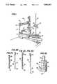
- FIG. 1is a perspective view of a stereotaxic apparatus modified for accepting the tissue transplantation apparatus of the present invention
- FIGS. 2A and 2Billustrate a first cannula assembly used to perform a first step in the method of tissue transplantation according to the present invention, FIG. 2A showing an outer guide cannula and FIG. 2B showing a stylet insertable within the outer guide cannula of FIG. 2A;
- FIGS. 2C and 2Dillustrate a second cannula assembly used in conjunction with the guide cannula of FIG. 2A to perform a further step in the method of tissue implantation according to the present invention, where FIG. 2C shows an inner cannula and FIG. 2D shows a stylet insertable within the inner cannula of FIG. 2C;
- FIG. 2Eillustrates a holder assembly for use with the second cannula assembly in performing a step of the method according to the invention
- FIG. 3Ashows the cannula assembly of FIG. 2A and 2B and illustrates the stylet of FIG. 2A disposed within the cannula of FIG. 2B;
- FIG. 3Billustrates the use of a first carrier of the stereotaxic apparatus of FIG. 1 with the first cannula assembly of FIGS. 2A and 2B for initially locating the position in a brain where the tissue will be implanted;
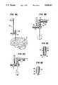
- FIG. 4Aillustrates the attachment of the holder assembly of FIG. 2E to the second cannula assembly of FIGS. 2C and 2D for the purpose of punching donor tissue prior to its implantation in the brain;
- FIG. 4Bis an enlarged view of the holder assembly shown in FIGS. 2E and 4A, and illustrating the manner of determining the amount of donor tissue to be retained for transplantation;
- FIG. 4Cshows the relative positions of the cannula and stylet of the second cannula assembly after the donor tissue has been retained
- FIG. 4Dis an enlarged view of the lower region of the cannula assembly of FIG. 4C, showing the manner in which donor tissue is retained;
- FIG. 5Aillustrates the use of the stereotaxic apparatus prior to implantation of the donor tissue in the brain
- FIG. 5Bshows the manner of attachment of the guide cannula of FIG. 2A and the second cannula assembly of FIGS. 2C and 2D to the stereotaxic apparatus prior to brain tissue implantation;
- FIG. 5Cis an enlarged view of the lower region of the guide cannula and second cannula assembly in FIG. 5B and showing the relative positions of the cannula components, stylet and donor tissue;
- FIG. 5Dillustrates the intended manner of using the stereotaxic apparatus to effect the implantation of donor tissue into the brain
- FIG. 5Eis an enlarged view of the lower end of the cannula shown in FIG. 5D illustrating the manner in which the donor tissue is released at the transplantation site.
- FIG. 1illustrates a known stereotaxic apparatus 100 (Model 1404 available from David Kopf Instruments, Tujunga, Calif.) which has been modified for use with the implantation apparatus (described in detail below) of the present invention. It is to be understood that the apparatus shown in FIG. 1 is only one example of a suitable stereotaxic device suited for use with the implantation apparatus of the present invention, and it is further contemplated that appropriate modifications of other stereotaxic devices for accepting the implantation apparatus are within the scope of skill of the ordinary artisan.
- Stereotaxic apparatus 100includes a first carrier 110 (Model 1460 available from David Kopf Instruments, Tujunga, CA) mounted on a lateral slide base 120 (Model 1262, available from David Kopf Instruments, Tujunga, CA), which is modified to support a second carrier 130.
- a first carrier 110Model 1460 available from David Kopf Instruments, Tujunga, CA
- a lateral slide base 120Model 1262, available from David Kopf Instruments, Tujunga, CA
- the modificationis made by providing a drilled hole at an end 122 of the base 120 remote from the first carrier 110 and in the vicinity of adjustment knob 124.
- the second carrier 130includes a vertical post 132, which is preferably a 7 mm diameter ⁇ 25 cm long stainless steel support post, and a horizontal support rod 134, which is preferably a 7 mm diameter ⁇ 10 cm long stainless steel element.
- One end 135 of rod 134is connected to vertical post 132 by a 90° clamp block 136, while the opposite end 137 of rod 134 is attached to a universal clamp-type holder 138.
- a universal clamp-type holder 118is also provided on the free end of vertical rod 117, the latter being suspended from the horizontal rod assembly 115 of the first carrier 110.
- the tissue implantation apparatus of the present inventionfurther includes first and second cannula assemblies and a holder assembly, as depicted in FIGS. 2A-2B, FIGS. 2C-2D and FIG. 2E, respectively.
- the first cannula assembly 10is employed for making initial penetrations into brain tissue during surgery, and includes an outer guide cannula 200 and a first stylet or occluder 300 interfitted within the cannula 200.
- Cannula 200includes a tube 210 and a tubular cap 220 having a bore of a diameter adapted to snuggly receive one end of tube 210 and which is secured to the one end of tube 210 by a soldered connection or the like.
- the other end of tube 210 distal from cap 220is beveled to form a cutting edge 230.
- the tube 310is 94 mm long and has a wall thickness of 0.23 mm, an outer diameter of 1.651 mm and an inner diameter of 1.193 mm; and the tubular cap 220 is 10 mm long and 8 mm in diameter.
- Stylet 300includes a solid rod member 310 preferably made of stainless steel having one end region secured by solder or the like within a bore drilled in a solid brass cap 320, and having its opposite end region 330 sharpened to provide a penetration bevel at the same angle as the bevel 230.
- the rod member 310has a length of about 105 mm and an outer diameter of about 1.066 mm, while the cap 320 is about 10 mm long and about 8 mm in outer diameter.
- the second cannula assembly 20which is employed along with cannula 200 for effecting tissue transplantation during surgery (as described below in greater detail), includes a second cannula 400 (FIG. 2C) and a second stylet or occluder 500 (FIG. 2D), and holder assembly 600 (FIG. 2E).
- Cannula 400includes a tube 410 having an outer wall milled slightly to fit within tube 210 of cannula 200, and a cap 420 secured at one end of the tube 410 by a solder connection made in a manner similar to the soldered connection of cap 220 to tube 210 of cannula 200.
- the end of tube 410 remote from cap 420is beveled to provide a sharpened cutting edge 430 suitable for punching into tissue to be transplanted.
- the preferred embodiment of the cannula 400which is adapted for use on monkeys has a length of about 104 mm, with the tube 410 having an inside diameter of about 0.685 mm, an outside diameter of about 1.066 mm and a wall thickness of abut 0.177 mm.
- the preferred embodiment of the cap 420has an outer diameter of 8 mm and a length of 10 mm.
- Stylet 500is similar to stylet 300 in construction; however, in the preferred embodiment of the invention, the outside diameter of rod 510 is about 0.558 mm and the overall length of the stylet 500 including cap 520 is about 115 mm.
- the distal end 530 of the stylet 500is desirably blunt rather than tapered or pointed.
- Holder assembly 600shown in FIG. 2E, is used with cannula 400 and stylet 500 for determining the amount of tissue to be transplanted, and for assisting in the precise deposition of the donor tissue in the brain at the transplant site (to be described in greater detail below).
- the holder assembly 600includes a tubular shell 610 into which the caps 520, 420 of stylet 500 and cannula 400, respectively, are inserted.
- a viewing slot 620is a viewing slot 620 by which a surgeon can determine the relative distance between the caps 520 and 420 of the stylet 500 and the cannula 400, and hence by direct correspondence the relative distance between the free ends 530, 430 of the stylet 500 and cannula 400 (the purpose of which is described below).
- a grouping 630 of graduation marks or lines, i.e. a linear scale,is located adjacent one side of viewing slot 620.
- the lines in grouping 630are spaced apart by predetermined distances (in the preferred embodiment, the lines are spaced apart from one another by about 1 mm).
- a set screw 640is provided at the upper end region of the tubular shell 610 for securing therein the cap 520 of stylet 500.
- a thumb screw 650provided at the lower end region cf the tubular shell 610, is coupled with and permits selective tightening or loosening of a clamp member 660 disposed within the shell so that end cap 420 of cannula 400 can be adjustably positioned, and secured within shell 610, at a desired location relative to the stylet end cap 520.
- a rod-like protrusion 670, located at the upper end of shell 610is adapted to be tightly gripped by holder 138 of the second carrier 130 supported on the stereotaxic apparatus 100 shown in FIG. 1.
- the method of tissue transplantation according to the present inventioninvolves essentially three steps:
- initial penetrations into the brain Bare effected through the use of the first cannula assembly 10 and the first carrier 110 of the stereotaxic apparatus 100 shown in FIG. 1.
- the first cannula assembly 10is secured to the first carrier 110, via holder 118, and positioned at the skull opening by appropriate manipulations of the controls of stereotaxic apparatus 100.
- First carrier 110is then moved vertically in the direction of arrow A until a desired penetration depth is reached by the distal end 230/330 the first cannula assembly 10.
- the stylet 300is removed, the cannula 200 remaining in place within the brain.
- the second cannula assembly 20is used to determine an amount of donor tissue to be transplanted, and to obtain and hold ready that determined amount of tissue until the step of deposition of the tissue is to be carried out.
- the second cannula assembly 20includes cannula 400, stylet 500 disposed concentrically within the 410 of cannula 400 (shown in FIG. 4C) and holder assembly 600.
- the second cannula assembly 20is used for the purpose of obtaining, e.g. by punching or cutting from a suitable source S an amount of donor tissue T.
- FIG. 4Dillustrates the relative positioning between the lower end 530 of the rod of the stylet 500 and the lower end of the tube 410 of the cannula 400 in order to accommodate a predetermined amount of tissue T.
- the selected volume of tissue Tis captured or retained within the lower end of the tube T.
- the second cannula assembly 20is inserted into the outer guide cannula 210 of the first cannula assembly 10 (see FIG. 5A), and the rod-like protrusion 670 top holder assembly 600 is affixed to clamp 138 of the stereotaxic apparatus, second carrier 130 (see FIG. 5B).
- the lower end 230 of the cannula 200is disposed slightly above the lower end 430 of cannula 400 (as shown in FIG. 5C) so that the lower ends of cannulas 200 and 400 exhibit one continuous bevelled surface.
- the thumb screw 650is turned so that clamp 660 is loosened.
- the first carrier 110is raised vertically relative to the second carrier 130 so that the tube 210 rides over the exterior surface of tube 410 until the end cap 220 of the cannula 200 abuts the end cap 420 of cannula 400.
- further vertical movement upwardly of the first carrier 110 relative to the second carrier 130causes end cap 420 (and hence cannula 400 of the second cannula assembly 20) to move upwardly relative to and toward the end cap 520 of stylet 500.
- the separation between end caps 420 an 520is visibly seen to diminish via viewing slot 620 and the tissue T held in the lower tubular region of cannula 400 is gradually and gently released into the transplant site.
- tissue transplantationrelates to tissue transplants at single sites as well as tissue transplants at multiple sites.
- the latteris accomplished by disconnecting the second carrier 130 from the holder assembly 600, lifting the first carrier 110 so that the "piggy-backed" cannulas 200, 400 are removed from the initial transplant site, and repeating the afore-described three step transplant procedure at a newly selected or defined transplant site.
- the preferred dimensions as indicated aboveare selected on the basis of experiments which have shown that the cross sectional size of cannula 400 as noted above, i.e. 0.685 mm, is the smallest that can be used to reliably punch adrenal medulla from the monkey, Macaca mulatta. Dimensions of the other cannula and stylets are determined by cannula 400. For use on humans, it is preferred that the maximum outer diameter of the tube 210 be no greater than 1.0 mm.
- Preliminary dataindicate that the present device is superior to other techniques for transplantation of adrenal medulla into the primate striatum. In a number of sites, tens of thousands of cells have survived while in other sites only a few cells survived. While the number of surviving cells is inconsistent, the tissue transplantation apparatus of the present invention affords better maximum survival of adrenal chromaffin cells than other techniques which have been used in monkeys.
- the survival of cells using the method and apparatus of the inventionis also superior to others known and/or practised for the parenchyma of the rat brain--where about 200 chromaffin cells per animal survive permanently when stereotaxically injected into the striatum in a fluid vehicle (Freed et al., 1986), or when transplanted by simply forcing the tissue from the needle with a stylet (Freed, unpublished data).
- the transplantation apparatuscan be easily guided to the transplantation site with a stereotaxic instrument, and it can be used for placing tissue into multiple sites along a single tract, or for placing tissue, when necessary, along multiple tracts.
- the brain tissue transplanter or graftercan be manufactured from readily available materials and its dimensions altered for animals with different sized brains.
- the brain tissue transplanter or graftercan be used not only with Macaca mulatta adrenal medulla, which is fairly fibrous and holds together well as a piece, but also for embryonic brain tissue, which is much more fragile and therefore more difficult to manipulate and insert without damage.
Landscapes
- Health & Medical Sciences (AREA)
- Surgery (AREA)
- Life Sciences & Earth Sciences (AREA)
- Heart & Thoracic Surgery (AREA)
- Molecular Biology (AREA)
- Oral & Maxillofacial Surgery (AREA)
- Engineering & Computer Science (AREA)
- Biomedical Technology (AREA)
- Nuclear Medicine, Radiotherapy & Molecular Imaging (AREA)
- Medical Informatics (AREA)
- Pathology (AREA)
- Animal Behavior & Ethology (AREA)
- General Health & Medical Sciences (AREA)
- Public Health (AREA)
- Veterinary Medicine (AREA)
- Surgical Instruments (AREA)
- Prostheses (AREA)
Abstract
Description
Claims (4)
Priority Applications (4)
| Application Number | Priority Date | Filing Date | Title |
|---|---|---|---|
| US07/278,821US5004457A (en) | 1988-12-02 | 1988-12-02 | Tissue transplantation system |
| AU48070/90AAU4807090A (en) | 1988-12-02 | 1989-12-04 | Tissue transplantation system |
| PCT/US1989/005427WO1990006141A1 (en) | 1988-12-02 | 1989-12-04 | Tissue transplantation system |
| US07/588,242US5006122A (en) | 1988-12-02 | 1990-09-20 | Tissue transplantation system |
Applications Claiming Priority (1)
| Application Number | Priority Date | Filing Date | Title |
|---|---|---|---|
| US07/278,821US5004457A (en) | 1988-12-02 | 1988-12-02 | Tissue transplantation system |
Related Child Applications (1)
| Application Number | Title | Priority Date | Filing Date |
|---|---|---|---|
| US07/588,242ContinuationUS5006122A (en) | 1988-12-02 | 1990-09-20 | Tissue transplantation system |
Publications (1)
| Publication Number | Publication Date |
|---|---|
| US5004457Atrue US5004457A (en) | 1991-04-02 |
Family
ID=23066513
Family Applications (1)
| Application Number | Title | Priority Date | Filing Date |
|---|---|---|---|
| US07/278,821Expired - LifetimeUS5004457A (en) | 1988-12-02 | 1988-12-02 | Tissue transplantation system |
Country Status (3)
| Country | Link |
|---|---|
| US (1) | US5004457A (en) |
| AU (1) | AU4807090A (en) |
| WO (1) | WO1990006141A1 (en) |
Cited By (33)
| Publication number | Priority date | Publication date | Assignee | Title |
|---|---|---|---|---|
| US5196019A (en)* | 1991-10-04 | 1993-03-23 | Dlp, Inc. | Goniometer for needle placement |
| US5254123A (en)* | 1992-02-24 | 1993-10-19 | Complete System Diagnostics, Inc. | Compressive device for ultrasound-guided repair of pseudoaneurysms |
| US5395317A (en)* | 1991-10-30 | 1995-03-07 | Smith & Nephew Dyonics, Inc. | Unilateral biportal percutaneous surgical procedure |
| US5441505A (en)* | 1993-01-28 | 1995-08-15 | Mitaka Kohki Co., Ltd. | Medical locating apparatus |
| US5464446A (en)* | 1993-10-12 | 1995-11-07 | Medtronic, Inc. | Brain lead anchoring system |
| US5487739A (en)* | 1987-11-17 | 1996-01-30 | Brown University Research Foundation | Implantable therapy systems and methods |
| US5637096A (en)* | 1990-12-27 | 1997-06-10 | Yoon; Inbae | Safety needle |
| US5762629A (en)* | 1991-10-30 | 1998-06-09 | Smith & Nephew, Inc. | Oval cannula assembly and method of use |
| US5776144A (en)* | 1996-05-10 | 1998-07-07 | Implex Gmbh Spezialhorgerate | Device for positioning and fixing of therapeutic, surgical, or diagnostic instruments |
| US5792044A (en)* | 1996-03-22 | 1998-08-11 | Danek Medical, Inc. | Devices and methods for percutaneous surgery |
| US5792110A (en)* | 1996-06-26 | 1998-08-11 | Cunningham; Miles G. | Systems and methods for delivering therapeutic agents to selected sites in a subject |
| US6152871A (en)* | 1996-03-22 | 2000-11-28 | Sdgi Holdings, Inc. | Apparatus for percutaneous surgery |
| US6162170A (en)* | 1996-03-22 | 2000-12-19 | Sdgi Holdings, Inc. | Devices and methods for percutaneous surgery |
| US20030057347A1 (en)* | 1998-07-02 | 2003-03-27 | Weiss Jeffrey N. | Apparatus and method for cannulating retinal blood vessels |
| US20030073998A1 (en)* | 2000-08-01 | 2003-04-17 | Endius Incorporated | Method of securing vertebrae |
| US6679833B2 (en) | 1996-03-22 | 2004-01-20 | Sdgi Holdings, Inc. | Devices and methods for percutaneous surgery |
| US20040111104A1 (en)* | 2002-08-23 | 2004-06-10 | Organ Recovery Systems | Cannulas, cannula mount assemblies, and clamping methods using such cannulas and cannula mount assemblies |
| US20040176763A1 (en)* | 1996-03-22 | 2004-09-09 | Foley Kevin T. | Methods for percutaneous surgery |
| US20040186346A1 (en)* | 1996-03-22 | 2004-09-23 | Smith Maurice M. | Devices and methods for percutaneous surgery |
| US20060241350A1 (en)* | 2005-04-22 | 2006-10-26 | Sdgi Holdings, Inc. | Instruments and methods for selective tissue retraction through a retractor sleeve |
| US20090192487A1 (en)* | 2006-07-27 | 2009-07-30 | University Of Virginia Patent Foundation | System and Method for Intracranial Implantation of Therapeutic or Diagnostic Agents |
| US20100063481A1 (en)* | 2008-09-08 | 2010-03-11 | Medrad, Inc. | Connector system having a compressible sealing element and a flared fluid path element to reduce fluid flow restrictions |
| US7985247B2 (en) | 2000-08-01 | 2011-07-26 | Zimmer Spine, Inc. | Methods and apparatuses for treating the spine through an access device |
| US8005571B2 (en) | 2002-08-13 | 2011-08-23 | Neuroarm Surgical Ltd. | Microsurgical robot system |
| US20130079799A1 (en)* | 2011-09-26 | 2013-03-28 | Korea Institute Of Science And Technology | Precise placement device for precise insertion of insert |
| US8540746B2 (en) | 1998-08-20 | 2013-09-24 | Zimmer Spine, Inc. | Cannula for receiving surgical instruments |
| US8828034B2 (en) | 2011-04-29 | 2014-09-09 | Lifeline Scientific, Inc. | Cannula |
| WO2015017543A3 (en)* | 2013-07-30 | 2015-03-26 | Massachusetts Institute Of Technology | Systems and methods for delivering chemical and electrical stimulation across one or more neural circuits |
| US9022978B2 (en) | 2011-04-29 | 2015-05-05 | Lifeline Scientific, Inc. | Universal sealring cannula |
| US9642625B2 (en) | 2011-04-29 | 2017-05-09 | Lifeline Scientific, Inc. | Cannula for a donor organ with or without an aortic cuff or patch |
| US9707049B1 (en)* | 2016-12-22 | 2017-07-18 | The Florida International University Board Of Trustees | Stereotactic device for implantation of permanent implants into a rodent brain |
| US10251722B1 (en) | 2018-09-17 | 2019-04-09 | The Florida International University Board Of Trustees | Stereotaxic brain implant system for large animals |
| US20210162134A1 (en)* | 2018-07-30 | 2021-06-03 | Kyoto University | Microsyringe unit |
Citations (14)
| Publication number | Priority date | Publication date | Assignee | Title |
|---|---|---|---|---|
| US2269936A (en)* | 1939-04-27 | 1942-01-13 | A E Dixon | Coin changer and control device |
| US2705949A (en)* | 1953-08-25 | 1955-04-12 | Silverman Irving | Biopsy needle |
| US3406685A (en)* | 1963-07-23 | 1968-10-22 | Becton Dickinson Co | Catheter needle and method for its manufacture |
| US3792703A (en)* | 1972-07-10 | 1974-02-19 | Deseret Pharma | Catheter placement unit |
| US4058114A (en)* | 1974-09-11 | 1977-11-15 | Siemens Aktiengesellschaft | Ultrasonic arrangement for puncturing internal body organs, vessels and the like |
| US4258067A (en)* | 1977-09-08 | 1981-03-24 | Ludwig Scheid GmbH Spezialpraparate und Gewurze zur Fleischverarbeitung | Method for introducing a pulverulent material into meat or the like |
| US4386602A (en)* | 1977-05-17 | 1983-06-07 | Sheldon Charles H | Intracranial surgical operative apparatus |
| US4571243A (en)* | 1983-05-18 | 1986-02-18 | Edward C. Froning | Needle guidance system |
| US4573448A (en)* | 1983-10-05 | 1986-03-04 | Pilling Co. | Method for decompressing herniated intervertebral discs |
| US4581019A (en)* | 1981-04-23 | 1986-04-08 | Curelaru Johan | Device for introducing a catheter-cannula into a blood vessel |
| US4613324A (en)* | 1985-06-17 | 1986-09-23 | Ghajar Jamshid B G | Method and apparatus for guiding catheter into ventricular system of human brain |
| US4834708A (en)* | 1987-03-31 | 1989-05-30 | George Pillari | Puncture needle assembly |
| US4846804A (en)* | 1988-03-24 | 1989-07-11 | Dlp Inc. | Combined needle protector and guidewire feeder |
| US4919653A (en)* | 1987-07-28 | 1990-04-24 | Martinez Antonio E | Device for locating the epidural space |
- 1988
- 1988-12-02USUS07/278,821patent/US5004457A/ennot_activeExpired - Lifetime
- 1989
- 1989-12-04AUAU48070/90Apatent/AU4807090A/ennot_activeAbandoned
- 1989-12-04WOPCT/US1989/005427patent/WO1990006141A1/enunknown
Patent Citations (14)
| Publication number | Priority date | Publication date | Assignee | Title |
|---|---|---|---|---|
| US2269936A (en)* | 1939-04-27 | 1942-01-13 | A E Dixon | Coin changer and control device |
| US2705949A (en)* | 1953-08-25 | 1955-04-12 | Silverman Irving | Biopsy needle |
| US3406685A (en)* | 1963-07-23 | 1968-10-22 | Becton Dickinson Co | Catheter needle and method for its manufacture |
| US3792703A (en)* | 1972-07-10 | 1974-02-19 | Deseret Pharma | Catheter placement unit |
| US4058114A (en)* | 1974-09-11 | 1977-11-15 | Siemens Aktiengesellschaft | Ultrasonic arrangement for puncturing internal body organs, vessels and the like |
| US4386602A (en)* | 1977-05-17 | 1983-06-07 | Sheldon Charles H | Intracranial surgical operative apparatus |
| US4258067A (en)* | 1977-09-08 | 1981-03-24 | Ludwig Scheid GmbH Spezialpraparate und Gewurze zur Fleischverarbeitung | Method for introducing a pulverulent material into meat or the like |
| US4581019A (en)* | 1981-04-23 | 1986-04-08 | Curelaru Johan | Device for introducing a catheter-cannula into a blood vessel |
| US4571243A (en)* | 1983-05-18 | 1986-02-18 | Edward C. Froning | Needle guidance system |
| US4573448A (en)* | 1983-10-05 | 1986-03-04 | Pilling Co. | Method for decompressing herniated intervertebral discs |
| US4613324A (en)* | 1985-06-17 | 1986-09-23 | Ghajar Jamshid B G | Method and apparatus for guiding catheter into ventricular system of human brain |
| US4834708A (en)* | 1987-03-31 | 1989-05-30 | George Pillari | Puncture needle assembly |
| US4919653A (en)* | 1987-07-28 | 1990-04-24 | Martinez Antonio E | Device for locating the epidural space |
| US4846804A (en)* | 1988-03-24 | 1989-07-11 | Dlp Inc. | Combined needle protector and guidewire feeder |
Cited By (69)
| Publication number | Priority date | Publication date | Assignee | Title |
|---|---|---|---|---|
| US6179826B1 (en) | 1987-11-17 | 2001-01-30 | Brown University Research Foundation | Implantable therapy systems and methods |
| US5487739A (en)* | 1987-11-17 | 1996-01-30 | Brown University Research Foundation | Implantable therapy systems and methods |
| US5637096A (en)* | 1990-12-27 | 1997-06-10 | Yoon; Inbae | Safety needle |
| US5196019A (en)* | 1991-10-04 | 1993-03-23 | Dlp, Inc. | Goniometer for needle placement |
| US5395317A (en)* | 1991-10-30 | 1995-03-07 | Smith & Nephew Dyonics, Inc. | Unilateral biportal percutaneous surgical procedure |
| US5762629A (en)* | 1991-10-30 | 1998-06-09 | Smith & Nephew, Inc. | Oval cannula assembly and method of use |
| US5254123A (en)* | 1992-02-24 | 1993-10-19 | Complete System Diagnostics, Inc. | Compressive device for ultrasound-guided repair of pseudoaneurysms |
| US5441505A (en)* | 1993-01-28 | 1995-08-15 | Mitaka Kohki Co., Ltd. | Medical locating apparatus |
| US5464446A (en)* | 1993-10-12 | 1995-11-07 | Medtronic, Inc. | Brain lead anchoring system |
| US20070156020A1 (en)* | 1996-03-22 | 2007-07-05 | Foley Kevin T | Methods for percutaneous spinal surgery |
| US6425859B1 (en) | 1996-03-22 | 2002-07-30 | Sdgi Holdings, Inc. | Cannula and a retractor for percutaneous surgery |
| US5902231A (en)* | 1996-03-22 | 1999-05-11 | Sdgi Holdings, Inc. | Devices and methods for percutaneous surgery |
| US5954635A (en)* | 1996-03-22 | 1999-09-21 | Sdgi Holdings Inc. | Devices and methods for percutaneous surgery |
| US6007487A (en)* | 1996-03-22 | 1999-12-28 | Sdgi Holdings, Inc. | Tissue retractor for use through a cannula |
| US6152871A (en)* | 1996-03-22 | 2000-11-28 | Sdgi Holdings, Inc. | Apparatus for percutaneous surgery |
| US6162170A (en)* | 1996-03-22 | 2000-12-19 | Sdgi Holdings, Inc. | Devices and methods for percutaneous surgery |
| US6176823B1 (en) | 1996-03-22 | 2001-01-23 | Sdgi Holdings, Inc. | Fixture for supporting a viewing element within a cannula |
| US5792044A (en)* | 1996-03-22 | 1998-08-11 | Danek Medical, Inc. | Devices and methods for percutaneous surgery |
| US6206822B1 (en) | 1996-03-22 | 2001-03-27 | Sdgi Holdings, Inc. | Devices and methods for percutaneous surgery |
| US6217509B1 (en) | 1996-03-22 | 2001-04-17 | Sdgi Holdings, Inc. | Devices and methods for percutaneous surgery |
| US7198598B2 (en) | 1996-03-22 | 2007-04-03 | Warsaw Orthopedic, Inc. | Devices and methods for percutaneous surgery |
| US6520907B1 (en) | 1996-03-22 | 2003-02-18 | Sdgi Holdings, Inc. | Methods for accessing the spinal column |
| US20040186346A1 (en)* | 1996-03-22 | 2004-09-23 | Smith Maurice M. | Devices and methods for percutaneous surgery |
| US20040176763A1 (en)* | 1996-03-22 | 2004-09-09 | Foley Kevin T. | Methods for percutaneous surgery |
| US20030139648A1 (en)* | 1996-03-22 | 2003-07-24 | Foley Kevin Thomas | Devices and methods for percutaneous surgery |
| US6679833B2 (en) | 1996-03-22 | 2004-01-20 | Sdgi Holdings, Inc. | Devices and methods for percutaneous surgery |
| US7993378B2 (en) | 1996-03-22 | 2011-08-09 | Warsaw Orthopedic, IN. | Methods for percutaneous spinal surgery |
| US5776144A (en)* | 1996-05-10 | 1998-07-07 | Implex Gmbh Spezialhorgerate | Device for positioning and fixing of therapeutic, surgical, or diagnostic instruments |
| US5792110A (en)* | 1996-06-26 | 1998-08-11 | Cunningham; Miles G. | Systems and methods for delivering therapeutic agents to selected sites in a subject |
| US20030057347A1 (en)* | 1998-07-02 | 2003-03-27 | Weiss Jeffrey N. | Apparatus and method for cannulating retinal blood vessels |
| US6916000B2 (en)* | 1998-07-02 | 2005-07-12 | Jeffrey N. Weiss | Apparatus and method for cannulating retinal blood vessels |
| US8540746B2 (en) | 1998-08-20 | 2013-09-24 | Zimmer Spine, Inc. | Cannula for receiving surgical instruments |
| US8777997B2 (en) | 2000-08-01 | 2014-07-15 | Zimmer Spine, Inc. | Method for securing vertebrae |
| US8277486B2 (en) | 2000-08-01 | 2012-10-02 | Zimmer Spine, Inc. | System for performing a procedure at a spinal location |
| US7056321B2 (en) | 2000-08-01 | 2006-06-06 | Endius, Incorporated | Method of securing vertebrae |
| US20050113833A1 (en)* | 2000-08-01 | 2005-05-26 | Davison Thomas W. | Method of securing vertebrae |
| US9622735B2 (en) | 2000-08-01 | 2017-04-18 | Zimmer Spine, Inc. | Method for securing vertebrae |
| US20030073998A1 (en)* | 2000-08-01 | 2003-04-17 | Endius Incorporated | Method of securing vertebrae |
| US9101353B2 (en) | 2000-08-01 | 2015-08-11 | Zimmer Spine, Inc. | Method of securing vertebrae |
| US7699877B2 (en) | 2000-08-01 | 2010-04-20 | Zimmer Spine, Inc. | Method of securing vertebrae |
| US7722530B2 (en) | 2000-08-01 | 2010-05-25 | Zimmer Spine, Inc. | Method of securing vertebrae |
| US7850695B2 (en) | 2000-08-01 | 2010-12-14 | Zimmer Spine, Inc. | Method of securing vertebrae |
| US7985247B2 (en) | 2000-08-01 | 2011-07-26 | Zimmer Spine, Inc. | Methods and apparatuses for treating the spine through an access device |
| US8864785B2 (en) | 2000-08-01 | 2014-10-21 | Zimmer Spine, Inc. | Method for securing vertebrae |
| US9220567B2 (en) | 2002-08-13 | 2015-12-29 | Neuroarm Surgical Ltd. | Microsurgical robot system |
| US8041459B2 (en) | 2002-08-13 | 2011-10-18 | Neuroarm Surgical Ltd. | Methods relating to microsurgical robot system |
| US8170717B2 (en) | 2002-08-13 | 2012-05-01 | Neuroarm Surgical Ltd. | Microsurgical robot system |
| US8005571B2 (en) | 2002-08-13 | 2011-08-23 | Neuroarm Surgical Ltd. | Microsurgical robot system |
| US8396598B2 (en) | 2002-08-13 | 2013-03-12 | Neuroarm Surgical Ltd. | Microsurgical robot system |
| US20040111104A1 (en)* | 2002-08-23 | 2004-06-10 | Organ Recovery Systems | Cannulas, cannula mount assemblies, and clamping methods using such cannulas and cannula mount assemblies |
| US8361091B2 (en) | 2002-08-23 | 2013-01-29 | Organ Recovery Systems, Inc. | Cannulas, cannula mount assemblies, and clamping methods using such cannulas and cannula mount assemblies |
| WO2004017838A3 (en)* | 2002-08-23 | 2004-06-24 | Organ Recovery Systems | Connectors, particularity for transplant organs |
| US20060241350A1 (en)* | 2005-04-22 | 2006-10-26 | Sdgi Holdings, Inc. | Instruments and methods for selective tissue retraction through a retractor sleeve |
| US7427264B2 (en) | 2005-04-22 | 2008-09-23 | Warsaw Orthopedic, Inc. | Instruments and methods for selective tissue retraction through a retractor sleeve |
| US9669198B2 (en)* | 2006-07-27 | 2017-06-06 | University Of Virginia Patent Foundation | System and method for intracranial implantation of therapeutic or diagnostic agents |
| US20090192487A1 (en)* | 2006-07-27 | 2009-07-30 | University Of Virginia Patent Foundation | System and Method for Intracranial Implantation of Therapeutic or Diagnostic Agents |
| US20100063481A1 (en)* | 2008-09-08 | 2010-03-11 | Medrad, Inc. | Connector system having a compressible sealing element and a flared fluid path element to reduce fluid flow restrictions |
| US8551074B2 (en) | 2008-09-08 | 2013-10-08 | Bayer Pharma AG | Connector system having a compressible sealing element and a flared fluid path element |
| US8828034B2 (en) | 2011-04-29 | 2014-09-09 | Lifeline Scientific, Inc. | Cannula |
| US9022978B2 (en) | 2011-04-29 | 2015-05-05 | Lifeline Scientific, Inc. | Universal sealring cannula |
| US9642625B2 (en) | 2011-04-29 | 2017-05-09 | Lifeline Scientific, Inc. | Cannula for a donor organ with or without an aortic cuff or patch |
| US9498299B2 (en)* | 2011-09-26 | 2016-11-22 | Korea Institute Of Science And Technology | Precise placement device for precise insertion of insert |
| US20130079799A1 (en)* | 2011-09-26 | 2013-03-28 | Korea Institute Of Science And Technology | Precise placement device for precise insertion of insert |
| WO2015017543A3 (en)* | 2013-07-30 | 2015-03-26 | Massachusetts Institute Of Technology | Systems and methods for delivering chemical and electrical stimulation across one or more neural circuits |
| US10933218B2 (en) | 2013-07-30 | 2021-03-02 | Massachusetts Institute Of Technology | Systems and methods for delivering chemical and electrical stimulation across one or more neural circuits |
| US9707049B1 (en)* | 2016-12-22 | 2017-07-18 | The Florida International University Board Of Trustees | Stereotactic device for implantation of permanent implants into a rodent brain |
| US10492882B2 (en) | 2016-12-22 | 2019-12-03 | The Florida International University Board Of Trustees | Stereotactic device for implantation of permanent implants into a rodent brain |
| US20210162134A1 (en)* | 2018-07-30 | 2021-06-03 | Kyoto University | Microsyringe unit |
| US10251722B1 (en) | 2018-09-17 | 2019-04-09 | The Florida International University Board Of Trustees | Stereotaxic brain implant system for large animals |
Also Published As
| Publication number | Publication date |
|---|---|
| AU4807090A (en) | 1990-06-26 |
| WO1990006141A1 (en) | 1990-06-14 |
Similar Documents
| Publication | Publication Date | Title |
|---|---|---|
| US5006122A (en) | Tissue transplantation system | |
| US5004457A (en) | Tissue transplantation system | |
| US4771660A (en) | Needle holder | |
| US9498248B2 (en) | Retainer for immobilizing an implanted catheter during stylet retraction, and stylet holder for use with same | |
| US5649936A (en) | Stereotactic guide apparatus for use with neurosurgical headframe | |
| US5242373A (en) | Medical seed implantation instrument | |
| US5057085A (en) | Stabilized aspiration biopsy needle assembly | |
| US3021842A (en) | Hypodermic needle guide | |
| US5030223A (en) | Head mounted stereotaxic apparatus | |
| US5817106A (en) | Stereotactic guide apparatus for use with neurosurgical headframe | |
| US4681103A (en) | Ultrasound guided surgical instrument guide and method | |
| US5643286A (en) | Microdrive for use in stereotactic surgery | |
| US5520657A (en) | Method and device for vessel location cannulation utilizing a unique needle and syringe device | |
| Hayden et al. | Construction and implantation of a permanent cannula for making injections into the lateral ventricle of the rat brain | |
| US5906574A (en) | Apparatus for vacuum-assisted handling and loading of radioactive seeds and spacers into implant needles within an enclosed visible radiation shield for use in therapeutic radioactive seed implantation | |
| US5279570A (en) | Needle assembly with a movable stylet controlled by a spacer mechanism | |
| DE19808220B4 (en) | Nadeltrokar | |
| CA2066774A1 (en) | Apparatus and method for soft tissue biopsy | |
| WO2005044335A3 (en) | Safety spinal catheter | |
| JP2001502937A (en) | Medical devices for placement of solid materials | |
| CN110215595A (en) | For protecting the method and apparatus of catheter tip and for the stereo directed fixing device of microtubular | |
| Crane et al. | Simple cannula for repeated intracerebral drug administration in rats | |
| US20240207010A1 (en) | Implantable guide device | |
| WO2001087414A3 (en) | Guide sheath for a medical instrument | |
| CN111529120A (en) | Intracranial implantation drainage device and small animal intracranial administration and cerebrospinal fluid collector |
Legal Events
| Date | Code | Title | Description |
|---|---|---|---|
| AS | Assignment | Owner name:UNITED STATES OF AMERICA, THE, AS REPRESENTED BY T Free format text:ASSIGNMENT OF ASSIGNORS INTEREST.;ASSIGNOR:STAUB, RICHARD A.;REEL/FRAME:005031/0275 Effective date:19881129 Owner name:UNITED STATES OF AMERICA, THE, AS REPRESENTED BY T Free format text:ASSIGNMENT OF ASSIGNORS INTEREST.;ASSIGNOR:FREED, WILLIAM J.;REEL/FRAME:005031/0277 Effective date:19881129 Owner name:UNITED STATES OF AMERICA, THE, AS REPRESENTED BY T Free format text:ASSIGNMENT OF ASSIGNORS INTEREST.;ASSIGNOR:WYATT, RICHARD J.;REEL/FRAME:005031/0279 Effective date:19881129 | |
| STCF | Information on status: patent grant | Free format text:PATENTED CASE | |
| REMI | Maintenance fee reminder mailed | ||
| FEPP | Fee payment procedure | Free format text:PAYOR NUMBER ASSIGNED (ORIGINAL EVENT CODE: ASPN); ENTITY STATUS OF PATENT OWNER: LARGE ENTITY | |
| FPAY | Fee payment | Year of fee payment:4 | |
| SULP | Surcharge for late payment | ||
| FEPP | Fee payment procedure | Free format text:PAYER NUMBER DE-ASSIGNED (ORIGINAL EVENT CODE: RMPN); ENTITY STATUS OF PATENT OWNER: LARGE ENTITY Free format text:PAYOR NUMBER ASSIGNED (ORIGINAL EVENT CODE: ASPN); ENTITY STATUS OF PATENT OWNER: LARGE ENTITY | |
| FPAY | Fee payment | Year of fee payment:8 | |
| FEPP | Fee payment procedure | Free format text:PAYER NUMBER DE-ASSIGNED (ORIGINAL EVENT CODE: RMPN); ENTITY STATUS OF PATENT OWNER: LARGE ENTITY Free format text:PAYOR NUMBER ASSIGNED (ORIGINAL EVENT CODE: ASPN); ENTITY STATUS OF PATENT OWNER: LARGE ENTITY | |
| FPAY | Fee payment | Year of fee payment:12 |