US5004049A - Low profile dual screen prepack - Google Patents
Low profile dual screen prepackDownload PDFInfo
- Publication number
- US5004049A US5004049AUS07/470,177US47017790AUS5004049AUS 5004049 AUS5004049 AUS 5004049AUS 47017790 AUS47017790 AUS 47017790AUS 5004049 AUS5004049 AUS 5004049A
- Authority
- US
- United States
- Prior art keywords
- screen
- wire
- sand
- mandrel
- wires
- Prior art date
- Legal status (The legal status is an assumption and is not a legal conclusion. Google has not performed a legal analysis and makes no representation as to the accuracy of the status listed.)
- Expired - Lifetime
Links
- 230000009977dual effectEffects0.000titleabstractdescription15
- 239000004576sandSubstances0.000claimsabstractdescription60
- 230000015572biosynthetic processEffects0.000claimsabstractdescription34
- 239000012530fluidSubstances0.000claimsabstractdescription33
- 239000000463materialSubstances0.000claimsdescription13
- 238000004519manufacturing processMethods0.000abstractdescription31
- 230000014759maintenance of locationEffects0.000abstractdescription16
- 239000004744fabricSubstances0.000description9
- XLYOFNOQVPJJNP-UHFFFAOYSA-NwaterSubstancesOXLYOFNOQVPJJNP-UHFFFAOYSA-N0.000description7
- 239000007789gasSubstances0.000description5
- 239000003129oil wellSubstances0.000description4
- 239000002002slurrySubstances0.000description4
- 238000001914filtrationMethods0.000description3
- 210000002445nippleAnatomy0.000description3
- 238000012856packingMethods0.000description3
- 229910001220stainless steelInorganic materials0.000description3
- RAHZWNYVWXNFOC-UHFFFAOYSA-NSulphur dioxideChemical compoundO=S=ORAHZWNYVWXNFOC-UHFFFAOYSA-N0.000description2
- 230000008901benefitEffects0.000description2
- 239000002184metalSubstances0.000description2
- 238000000034methodMethods0.000description2
- 238000012986modificationMethods0.000description2
- 230000004048modificationEffects0.000description2
- 239000002245particleSubstances0.000description2
- 230000002028prematureEffects0.000description2
- 238000011084recoveryMethods0.000description2
- 239000007787solidSubstances0.000description2
- 125000006850spacer groupChemical group0.000description2
- 239000010935stainless steelSubstances0.000description2
- 238000010618wire wrapMethods0.000description2
- RWSOTUBLDIXVET-UHFFFAOYSA-NDihydrogen sulfideChemical compoundSRWSOTUBLDIXVET-UHFFFAOYSA-N0.000description1
- 229910000831SteelInorganic materials0.000description1
- 238000009825accumulationMethods0.000description1
- 239000011324beadSubstances0.000description1
- 239000004568cementSubstances0.000description1
- 239000000919ceramicSubstances0.000description1
- 239000011248coating agentSubstances0.000description1
- 238000000576coating methodMethods0.000description1
- 239000011246composite particleSubstances0.000description1
- 150000001875compoundsChemical class0.000description1
- 238000005260corrosionMethods0.000description1
- 230000007797corrosionEffects0.000description1
- 230000008878couplingEffects0.000description1
- 238000010168coupling processMethods0.000description1
- 238000005859coupling reactionMethods0.000description1
- 238000013461designMethods0.000description1
- 238000011161developmentMethods0.000description1
- 230000007613environmental effectEffects0.000description1
- 239000003822epoxy resinSubstances0.000description1
- 230000003628erosive effectEffects0.000description1
- 239000011521glassSubstances0.000description1
- 239000008187granular materialSubstances0.000description1
- 229910000037hydrogen sulfideInorganic materials0.000description1
- 238000007689inspectionMethods0.000description1
- 238000009434installationMethods0.000description1
- 230000009545invasionEffects0.000description1
- 238000012544monitoring processMethods0.000description1
- 239000003921oilSubstances0.000description1
- 239000011236particulate materialSubstances0.000description1
- 230000035699permeabilityEffects0.000description1
- 229920000647polyepoxidePolymers0.000description1
- 230000009467reductionEffects0.000description1
- 230000000717retained effectEffects0.000description1
- 238000007789sealingMethods0.000description1
- 238000004513sizingMethods0.000description1
- 239000010959steelSubstances0.000description1
- 235000010269sulphur dioxideNutrition0.000description1
- 239000004291sulphur dioxideSubstances0.000description1
- 238000012360testing methodMethods0.000description1
- 238000003466weldingMethods0.000description1
- 239000002759woven fabricSubstances0.000description1
Images

Classifications
- B—PERFORMING OPERATIONS; TRANSPORTING
- B01—PHYSICAL OR CHEMICAL PROCESSES OR APPARATUS IN GENERAL
- B01D—SEPARATION
- B01D24/00—Filters comprising loose filtering material, i.e. filtering material without any binder between the individual particles or fibres thereof
- B01D24/02—Filters comprising loose filtering material, i.e. filtering material without any binder between the individual particles or fibres thereof with the filter bed stationary during the filtration
- B01D24/04—Filters comprising loose filtering material, i.e. filtering material without any binder between the individual particles or fibres thereof with the filter bed stationary during the filtration the filtering material being clamped between pervious fixed walls
- B01D24/08—Filters comprising loose filtering material, i.e. filtering material without any binder between the individual particles or fibres thereof with the filter bed stationary during the filtration the filtering material being clamped between pervious fixed walls the filtering material being supported by at least two pervious coaxial walls
- E—FIXED CONSTRUCTIONS
- E21—EARTH OR ROCK DRILLING; MINING
- E21B—EARTH OR ROCK DRILLING; OBTAINING OIL, GAS, WATER, SOLUBLE OR MELTABLE MATERIALS OR A SLURRY OF MINERALS FROM WELLS
- E21B43/00—Methods or apparatus for obtaining oil, gas, water, soluble or meltable materials or a slurry of minerals from wells
- E21B43/02—Subsoil filtering
- E21B43/08—Screens or liners
- E21B43/082—Screens comprising porous materials, e.g. prepacked screens
Definitions
- This inventionrelates generally to apparatus for completing downhole wells, and in particular to well screens for filtering unconsolidated material out of inflowing well fluid in water, oil, gas and recovery wells.
- the well boreis uncased, and an open face is established across the oil or gas bearing zone.
- open bore hole (uncased) arrangementsare utilized, for example, in water wells, test wells and horizontal well completions.
- One or more sand screensare installed in the flow path between the production tubing and the perforated casing (cased) or the open well bore face (uncased).
- a packeris customarily set above the sand screen to seal off the annulus in the zone where production fluids flow into the production tubing.
- the annulus around the screenis packed with a relatively coarse sand or gravel which acts as a filter to reduce the amount of fine formation sand reaching the screen.
- a work string and service seal unit (SSU)is used to spot the gravel around the screen.
- gravelis also pumped and squeezed into the producing formation around the screen for filtering unconsolidated material out of the infilling well fluid.
- the gravelis pumped down the work string in a slurry of water or gel and is spotted directly under the packer or above the sand screen.
- the gravelalso fills the annulus between the sand screen and the well casing.
- the gravel packsupports the surrounding unconsolidated formation.
- Conventional sand screensemploy a perforated mandrel which is surrounded by longitudinally extending spacer bars, rods or ribs and over which a continuous wire is wrapped in a carefully spaced spiral configuration to provide a predetermined axial gap between the wire turns. See, for example, U.S. Pat. No. 3,784,409; U.S. Pat. No. 3,958,634; and U.S. Pat. No. 3,908,256, all assigned to Howard Smith Screen Company of Houston, Texas, and each being incorporated herein by reference.
- the aperture between turnspermits formation fluids to flow through the screen, while the closely spaced wire turns exclude fine particulate material such as sand or gravel which may penetrate the gravel pack.
- a problem which arises during initial production following the gravel packing operationis that fine sand may be carried through the gravel pack before the gravel pack bridge stabilizes It is not unusual to produce a substantial amount of such fin sands before the gravel pack finally consolidates and yields clean production During the early stages of producing the well after gravel packing, those fines tend to migrate through the gravel pack and screen and lodge within the inner annulus between the outer wire wrap and the perforated mandrel In some instances, this can cause severe erosion of the screen and ultimate failure of the screen to reduce sand invasion In other situations, the sand fines may include plugging materials which are carbonaceous, siliceous or organic solids which can completely plug the mandrel flow passages and terminate production shortly after completion.
- the formation pressurecan collapse the screen and production tubing.
- the formationmay collapse with resultant damage to the well casing or liner and consequent reduction or termination of production.
- One attempt to overcome the foregoing problemis to interpose a prepack of gravel within the annulus between the inner mandrel and the outer wire screen.
- the prepacked gravelis sized appropriately to exclude the fines which accompany the formation fluid during initial production.
- Raw gravel, as well as epoxy resin coated gravel,have been used extensively in prepacked well screens.
- Most prepacked well screensare subject to retrieval problems due to their outer diameter being larger than that of a conventional well screen.
- the inner mandrelis usually downsized, therefore creating restrictions in both production and completion tool string sizing.
- the principal object of the inventionis to provide a prepack sand screen which can exclude sand fines from inflowing formation fluid during the initial production phase following a gravel pack operation, without limiting production of formation fluid.
- a related object of the present inventionis to maximize the annular placement and retention of aggregate gravel materials in a sand screen having a maximum inner diameter and a minimum outer diameter.
- Another object of this inventionis to provide an improved prepacked well screen which maximizes the radial thickness of prepack gravel material without imposing a flow restriction or a strength compromise on the inner mandrel.
- a prepack well screen assemblyhaving inner and outer screens concentrically mounted in radially spaced relation onto an inner mandrel.
- the outer screenis radially spaced with respect to the inner screen, thereby defining a prepack annulus for receiving prepack gravel.
- the longitudinal spacing distance between adjacent turnsselectively excludes sand fines of a predetermined minimum size.
- the outer screen wireis substantially greater in size than the corresponding dimension of the inner retention screen wire. Accordingly, the effective inlet flow area through the inner retention screen is more than twice the effective inlet flow area through the outer screen in any selected zone of sand screen interface area.
- the inner screenis radially spaced with respect to the mandrel, thereby defining a flow bypass annulus.
- Bypass flow passagesare established across the entire interface zone between the gravel prepack and flow passages formed in the mandrel. Localized deposits of sand fines on the inner screen are effectively bypassed by the remaining rectangular flow passages formed across the inner screen.
- FIG. 1is an elevational view, partially in section and partially broken away, of an oil well completion at a producing zone, with a work string performing a gravel pack operation;
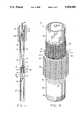
- FIG. 2is a perspective view, partially broken away, of a dual screen prepack assembly constructed according to the teachings of the present invention
- FIG. 3is an elevational view, partially broken away, of the dual screen prepack assembly shown in FIG. 2;
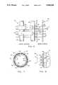
- FIG. 4is a sectional view of the dual screen prepack assembly taken along the lines 4--4 of FIG. 3;
- FIG. 5is an enlarged sectional view of a portion of the dual screen prepack assembly taken along the lines 5--5 of FIG. 4;
- FIG. 6is an enlarged perspective view of the outer screen and inner screen, partially broken away, of the dual screen prepack assembly shown in FIG. 2;
- FIG. 7is a sectional view of an alternative embodiment of the dual screen prepack assembly.
- FIG. 8is an enlarged perspective view of the outer screen and inner screen, partially broken away, of the dual screen prepack assembly shown in FIG. 7.
- FIG. 1 and FIG. 2a dual screen prepack assembly 10 is shown incorporated in a conventional oil well completion.
- a well bore 12has been reinforced by tubular casing 14 and sealed with cement 16.
- a production tubing 18has been run inside the casing 14.
- the casing 14is perforated by openings 20 at the depth where production fluids are to flow from the producing zone of the well into the production tubing 18.
- the sand screen 10is located opposite the perforations 20 in the casing as the production tubing 18 is run into the well, or it may be run directly opposite an open formation.
- the annulus between the production tubing and the casing 14is sealed off by an upper packer 22 and a lower packer 24 to produce formation fluids from the producing zone only.
- Flow ports 26are provided in the tubing string 18 below the upper packer 22 and above the sand screen 10 through which gravel mixed with water or gel is injected or circulated by a service seal unit (SSU) into the annulus 28 between the casing 14 and the sand screen 10.
- SSUservice seal unit
- a wash pipe 30is run inside the tubing string 18 to spot the gravel slurry of water and/or gel below the sand screen 10 or around a telltale screen 32 which is mounted below the primary sand screen 10.
- a polished bore nipple 34is run between the primary screen 10 and the telltale screen 32 in which the wash pipe 30 is landed in sealing engagement in order to circulate the slurry to the telltale screen 32. In this way, any premature spotting of gravel is prevented.
- the surface pumpswill indicate a pressure jump, which serves to squeeze the remaining water and/or gel from the annulus into the formation. The slurry of gel and gravel is then dehydrated by the oil or gas bearing formation. At the same time, the perforations 20 are filled with gravel. A greater jump in pressure indicates the conclusion of the gravel pack operation.
- the wash pipe 30is pulled out of the polished nipple 34 and the service seal unit SSU is pulled out of engagement with the packer 22 by retraction of a work string 36.
- the primary sand screen 10is illustrated in detail in FIG. 2.
- the primary sand screen 10is a dual screen prepacked assembly which includes a perforated tubular mandrel 38 of a predetermined length, for example, 20 feet.
- the tubular mandrel 38is perforated by radial bore flow passages 40 which follow parallel spiral paths along the length of the mandrel 38.
- the bore flow passages 40provide for fluid flow through the mandrel to the extent permitted by an external screen 42 and an internal screen 44.
- the bore flow passages 40may be arranged in any desired pattern and may vary in number in accordance with the area needed to accommodate the expected formation fluid flow through the production tubing 18.
- the perforated mandrel 38preferably is fitted with a threaded pin connection 46 at its opposite ends for threaded coupling with the polished nipple 34 and the production tubing 18.
- the outer wire screen 42is attached onto the mandrel 38 at opposite end portions thereof by annular end welds 48.
- the outer screen 42is a fluid-porous, particulate-restricting member which is formed separately from the mandrel 38.
- the outer screen 42has an outer screen wire 50 which is wrapped in multiple turns onto longitudinally extending outer ribs 52, preferably in a helical wrap.
- the turns of the outer screen wire 50are longitudinally spaced apart from each other thereby defining rectangular fluid flow apertures Z therebetween for conducting formation fluid flow while excluding sand and other unconsolidated formation material.
- the outer screen wire 50is typically 90 mils wide by 140 mils tall in a generally trapezoidal cross section.
- the maximum longitudinal spacing A between adjacent turns of the outer wire wrapis determined by the maximum diameter of the fines which are to be excluded.
- the aperture spacing A between adjacent wire turnsis 20 mils. This provides approximately 20 square inches of inlet flow area per linear foot in a screen 10 having an outside diameter of 2.97 inches.
- the outer screen wire 50 and the outer ribs 52are formed of stainless steel or other weldable material and are joined together by resistance welds W at each crossing point of the outer screen wire 50 onto the outer ribs 52 so that the screen 42 is a unitary assembly which is self-supporting prior to being mounted onto the mandrel 38.
- the outer ribs 52are circumferentially spaced with respect to each other and have a predetermined diameter for establishing a gravel prepack annulus 54 of an appropriate size for receiving a volume of gravel 56.
- the longitudinal ribs 52serve as spacers between the inner screen 44 and the outer screen 42.
- the prepacked gravel 56 and the surrounding screenmust be capable of withstanding rough run-in handling as well as extreme downhole well production conditions, such as a temperature range of from about 50° C. to about 300° C., a formation fluid pH of from about 6 to about 12, high formation pressure up to about 2,000 psi, and contact with corrosive formation fluids containing sulfurous compounds such as hydrogen sulfide or sulphur dioxide in concentrations up to about 20 g by weight.
- extreme downhole well production conditionssuch as a temperature range of from about 50° C. to about 300° C., a formation fluid pH of from about 6 to about 12, high formation pressure up to about 2,000 psi, and contact with corrosive formation fluids containing sulfurous compounds such as hydrogen sulfide or sulphur dioxide in concentrations up to about 20 g by weight.
- the prepack gravel 56preferably comprise gravel particles which are generally spherical in shape to provide high permeability within the prepack annulus 54.
- the prepacked gravel 56is sized appropriately to exclude the sand fines which accompany the formation fluid during initial production.
- the gravel 56can be coarse sand, glass or ceramic beads, solid polymeric granules, composite particles having a metal core surrounded by a corrosion resistant metal coating, and the like, which are sized appropriately to permit passage of formation fluid through the consolidated gravel particles while substantially preventing flow of sand and other unconsolidated formation materials therethrough.
- the inner screen 44is concentrically disposed about the tubular mandrel 38, and is concentrically disposed within the outer screen 42.
- the inner retention screen 44is thus stabilized by engagement against the outer longitudinal ribs 52.
- the prepack annulus 54is defined between the inner wire screen 44 and the outer wire screen 42.
- the fines which are initially produced following a gravel pack operationhave a fairly small grain diameter, for example, 20-40 mesh sand. Accordingly, the spacing dimension A (FIG. 5) between adjacent turns of the outer screen wire 50 is selected to exclude sand fines which exceed 20 mesh.
- the inner screen 44is separately formed from the mandrel 38 and from the outer screen 42 by a narrow gauge stainless steel wire 60 which is wrapped onto longitudinally extending inner ribs 62, preferably in a helical wrap.
- the turns of the inner screen wire 60are axially spaced apart from each other by the same spacing distance A as the outer screen wire turns 50, thereby providing rectangular fluid flow passages Q for conducting formation fluid while excluding sand fines
- the inner screen wire 60 and the inner ribs 62are formed of stainless steel or other weldable material and are joined together by resistance welds W at each crossing point of the inner screen wire 60 onto the inner ribs 62 so that the inner screen 44 is a unitary assembly which is self-supporting prior to being mounted onto the outer screen 42.
- the inner screen 44After the inner screen 44 has been separately assembled, it is mounted onto the perforated mandrel 38. That is, the mandrel 38 is inserted into the bore of the inner screen 44.
- the separately assembled outer screen 42is mounted onto the inner screen/mandrel subassembly.
- the outer ribs 52, the inner ribs 62, the inner wrapping wire 60 and the outer wrapping wire 50are welded together onto the lower end of the mandrel 38 by the annular weld 48.
- the gravel 56is then loaded into the open prepack annulus 54 at the opposite open end. The gravel 56 is retained within the prepack annulus by the annular weld 48, the outer screen 42 and the inner screen 44.
- the dual prepack screen 10becomes a unitary part of the mandrel 38 and is ready for service.
- the inner screen 44serves two purposes. First, it is a retention screen which retains the gravel 56 within the prepack annulus 54. Moreover, the longitudinal inner ribs 62 stabilize the inner screen wire turns 60 while also serving as a standoff for spacing the inner screen wire turns 60 radially with respect to the external surface of the mandrel 38. According to this arrangement, bypass flow passages are established across the entire interface zone between the gravel prepack 56 and the flow passages 40. That is, localized deposits of sand fines on the inner screen 44 are effectively bypassed by the remaining rectangular flow passages g formed across the inner screen 44.
- the outer screen 42also retains the gravel 56 within the prepack annulus 54.
- the outer longitudinal ribs 52provide radial spacing between the inner screen 44 and outer screen 42, thereby centering the inner screen concentrically within the outer screen.
- production flowis not limited or blocked by such localized accumulation of fines on the inner screen 44 for the reason that the effective inlet flow area of the inner retention screen 44 is substantially greater than the effective inlet flow area of the outer screen 42.
- Thisis made possible by selecting the size of the screen wire 60 and the longitudinal rib 62 of the inner screen to be substantially smaller than the corresponding screen wire 50 and longitudinal rib 52 of the outer screen.
- a limitation on the inner screen wire sizeis the minimum diameter of the rib 62 and the circumferential spacing of the ribs 62 to provide standoff clearance of the inner wire 60 with respect to the external surface of the perforated mandrel 38, and also the minimum size required whereby the inner wire 60 can be reliably joined to the rib 62 by resistance welding techniques.
- the diameters of both the inner rib 62 and the inner screen wire 60are preferably in the range of from about 0.016 inch to about 0.055 inch.
- the effective inlet flow area of the inner retention screen 44is substantially greater than the inlet flow area of the outer screen 42.
- the longitudinal spacing distance (A) between adjacent turnsis equal.
- the outer screen wireis substantially greater in the longitudinal dimension L than the diameter D of the inner retention screen wire 60.
- the outer screen wire 50has a generally trapezoidal cross section, and is joined by a resistance weld W onto the underlying rib 52.
- the longitudinal width dimension L of the outer wire 50 in this exampleis 90 mils.
- the corresponding longitudinal diameter dimension D of the inner wire 60is 20 mils. Accordingly, the effective inlet flow area through the inner retention screen 44 is more than twice the effective inlet flow area through the outer screen 42 in any selected zone of sand screen interface area.
- FIG. 6Another advantage of the radially offset inner screen arrangement as shown in FIG. 6 is that bridging or plugging of the inner rectangular flow passages is unlikely to occur because the surface area of the inner wire turns 60 and the inner longitudinal ribs 62 which frame the rectangular flow passages Q are relatively narrow and provide only minimum subjacent support for a sand bridge or plug.
- the wire meshis wrapped directly onto the mandrel, with the mandrel providing subjacent support on which a sand bridge or plug can more readily be established.
- an alternative dual screen prepack assembly 10'is illustrated.
- the inner screen wire 60is wrapped directly onto the mandrel 38 with adjacent turns being spaced by a longitudinal distance A. That is, the longitudinally extending rib wires 62 are not utilized in this alternative embodiment. Instead, the inner screen wire 60 is wrapped directly onto the perforated mandrel 38, for example, by the method as disclosed in U.S. Pat. No. 3,785,409; U.S. Pat. No. 3,958,634; and U.S. Pat. No. 3,908,256, all assigned to the assignee of the present invention, Howard Smith Screen Company of Houston, Tex.
- the longitudinal spacing distance A between adjacent inner screen wire turns 60is preferably equal to the longitudinal spacing distance A between the outer screen wire turns 50.
- the alternative dual screen embodiment 10'is identical to the preferred dual screen embodiment 10, except that the longitudinally extending inner rib wires 62 are not utilized, and the inner screen wire 60 is wrapped directly onto the perforated mandrel 38. Fluid flow through the flow apertures Q of the inner screen 44' occurs only through the area of the inner screen 44' which overlaps the mandrel flow apertures 40. However, it will be appreciated that the effective inlet flow area through the inner retention screen 44' is substantially greater than the effective inlet flow area through the outer screen 42 in any selected zone of the sand screen interface area.
- the effective inlet flow area through the inner retention screen 44'is more than twice the effective inlet flow area through the outer screen 42 in any selected zone of sand screen interface area.
Landscapes
- Chemical & Material Sciences (AREA)
- Mining & Mineral Resources (AREA)
- Geology (AREA)
- Life Sciences & Earth Sciences (AREA)
- Engineering & Computer Science (AREA)
- Fluid Mechanics (AREA)
- Environmental & Geological Engineering (AREA)
- Physics & Mathematics (AREA)
- Dispersion Chemistry (AREA)
- General Life Sciences & Earth Sciences (AREA)
- Geochemistry & Mineralogy (AREA)
- Chemical Kinetics & Catalysis (AREA)
- Filtering Materials (AREA)
Abstract
Description
This invention relates generally to apparatus for completing downhole wells, and in particular to well screens for filtering unconsolidated material out of inflowing well fluid in water, oil, gas and recovery wells.
1. Background of the Invention
In the course of completing an oil and/or gas well, it is common practice to run a string of casing into the well bore and then to run the actual production tubing inside the casing. At the well site, the casing is perforated across one or more production zones to allow production fluids to enter the casing bore. During production of the formation fluid, formation sand is also swept into the flow path. The formation sand is relatively fine sand that erodes production components in the flow path.
In some completions, the well bore is uncased, and an open face is established across the oil or gas bearing zone. Such open bore hole (uncased) arrangements are utilized, for example, in water wells, test wells and horizontal well completions.
One or more sand screens are installed in the flow path between the production tubing and the perforated casing (cased) or the open well bore face (uncased). A packer is customarily set above the sand screen to seal off the annulus in the zone where production fluids flow into the production tubing. The annulus around the screen is packed with a relatively coarse sand or gravel which acts as a filter to reduce the amount of fine formation sand reaching the screen. A work string and service seal unit (SSU) is used to spot the gravel around the screen. During well completion, gravel is also pumped and squeezed into the producing formation around the screen for filtering unconsolidated material out of the infilling well fluid. The gravel is pumped down the work string in a slurry of water or gel and is spotted directly under the packer or above the sand screen. The gravel also fills the annulus between the sand screen and the well casing. In well installations in which the screen is suspended in an uncased open bore, the gravel pack supports the surrounding unconsolidated formation.
2. Description of the Prior Art
Conventional sand screens employ a perforated mandrel which is surrounded by longitudinally extending spacer bars, rods or ribs and over which a continuous wire is wrapped in a carefully spaced spiral configuration to provide a predetermined axial gap between the wire turns. See, for example, U.S. Pat. No. 3,784,409; U.S. Pat. No. 3,958,634; and U.S. Pat. No. 3,908,256, all assigned to Howard Smith Screen Company of Houston, Texas, and each being incorporated herein by reference. The aperture between turns permits formation fluids to flow through the screen, while the closely spaced wire turns exclude fine particulate material such as sand or gravel which may penetrate the gravel pack.
A problem which arises during initial production following the gravel packing operation is that fine sand may be carried through the gravel pack before the gravel pack bridge stabilizes It is not unusual to produce a substantial amount of such fin sands before the gravel pack finally consolidates and yields clean production During the early stages of producing the well after gravel packing, those fines tend to migrate through the gravel pack and screen and lodge within the inner annulus between the outer wire wrap and the perforated mandrel In some instances, this can cause severe erosion of the screen and ultimate failure of the screen to reduce sand invasion In other situations, the sand fines may include plugging materials which are carbonaceous, siliceous or organic solids which can completely plug the mandrel flow passages and terminate production shortly after completion. In deep wells, when the screen becomes plugged and the pressure in the production tubing is reduced, the formation pressure can collapse the screen and production tubing. Moreover, when a substantial amount of sand has been lost from the surrounding formation, the formation may collapse with resultant damage to the well casing or liner and consequent reduction or termination of production.
One attempt to overcome the foregoing problem is to interpose a prepack of gravel within the annulus between the inner mandrel and the outer wire screen. The prepacked gravel is sized appropriately to exclude the fines which accompany the formation fluid during initial production. Raw gravel, as well as epoxy resin coated gravel, have been used extensively in prepacked well screens. Most prepacked well screens are subject to retrieval problems due to their outer diameter being larger than that of a conventional well screen. In order to make prepacked well screens more easily retrievable, the inner mandrel is usually downsized, therefore creating restrictions in both production and completion tool string sizing.
Some prior art well screens have utilized an inner wirecloth or steel woven fabric filter media in order to achieve maximum annular placement and retention of prepacked filter materials. See, for example, U.S. Pat. No. 4,858,691, and U.S. Pat. No. 4,856,591. Such woven wire cloth retainers do not provide free flow comparable to the conventional rib-channel design which is characteristic of resistance welded well screens. The wire-cloth retainer which is wrapped directly onto the perforated mandrel only permits free flow to occur where it overlaps flow passages on the mandrel. Even in this instance, flow through the perforations is further restricted where the wire cloth retainer overlaps itself.
The prior art sand screens which utilize fine wire woven cloth retainers can result in plugging due to the fact that the openings in the wire cloth are typically considerably smaller than the flow openings in the outer screen member. In U.S. Pat. No. 4,858,691, for example, the wire-cloth fabric mesh is stated to have a mesh size of from about 40 to about 200, which can have a substantially smaller inlet flow area than the inlet flow area of the outer particulate restricting cylinder It will be seen that sand plugging can interfere with the initial development phase of production in wells which are completed by wire cloth fabric mesh screens of the type described in U.S. Pat. No. 4,858,691.
The principal object of the invention is to provide a prepack sand screen which can exclude sand fines from inflowing formation fluid during the initial production phase following a gravel pack operation, without limiting production of formation fluid.
A related object of the present invention is to maximize the annular placement and retention of aggregate gravel materials in a sand screen having a maximum inner diameter and a minimum outer diameter.
Another object of this invention is to provide an improved prepacked well screen which maximizes the radial thickness of prepack gravel material without imposing a flow restriction or a strength compromise on the inner mandrel.
The foregoing objects are provided according to a preferred embodiment of the present invention by a prepack well screen assembly having inner and outer screens concentrically mounted in radially spaced relation onto an inner mandrel. The outer screen is radially spaced with respect to the inner screen, thereby defining a prepack annulus for receiving prepack gravel. In both screens, the longitudinal spacing distance between adjacent turns selectively excludes sand fines of a predetermined minimum size. The outer screen wire is substantially greater in size than the corresponding dimension of the inner retention screen wire. Accordingly, the effective inlet flow area through the inner retention screen is more than twice the effective inlet flow area through the outer screen in any selected zone of sand screen interface area. In one embodiment, the inner screen is radially spaced with respect to the mandrel, thereby defining a flow bypass annulus.
Bypass flow passages are established across the entire interface zone between the gravel prepack and flow passages formed in the mandrel. Localized deposits of sand fines on the inner screen are effectively bypassed by the remaining rectangular flow passages formed across the inner screen.
Operational features and advantages of the present invention will be understood by those skilled in the art upon reading the detailed description which follows with reference to the attached drawings.
FIG. 1 is an elevational view, partially in section and partially broken away, of an oil well completion at a producing zone, with a work string performing a gravel pack operation;
FIG. 2 is a perspective view, partially broken away, of a dual screen prepack assembly constructed according to the teachings of the present invention;
FIG. 3 is an elevational view, partially broken away, of the dual screen prepack assembly shown in FIG. 2;
FIG. 4 is a sectional view of the dual screen prepack assembly taken along thelines 4--4 of FIG. 3;
FIG. 5 is an enlarged sectional view of a portion of the dual screen prepack assembly taken along thelines 5--5 of FIG. 4;
FIG. 6 is an enlarged perspective view of the outer screen and inner screen, partially broken away, of the dual screen prepack assembly shown in FIG. 2;
FIG. 7 is a sectional view of an alternative embodiment of the dual screen prepack assembly; and,
FIG. 8 is an enlarged perspective view of the outer screen and inner screen, partially broken away, of the dual screen prepack assembly shown in FIG. 7.
In the description which follows, like parts are indicated throughout the specification and drawings with the same reference numerals, respectively. The drawings are not necessarily to scale and the proportions of certain parts have been exaggerated to better illustrate details of the invention.
Referring now to FIG. 1 and FIG. 2, a dualscreen prepack assembly 10 is shown incorporated in a conventional oil well completion. A well bore 12 has been reinforced bytubular casing 14 and sealed withcement 16. Aproduction tubing 18 has been run inside thecasing 14. Thecasing 14 is perforated byopenings 20 at the depth where production fluids are to flow from the producing zone of the well into theproduction tubing 18.
Thesand screen 10 is located opposite theperforations 20 in the casing as theproduction tubing 18 is run into the well, or it may be run directly opposite an open formation. The annulus between the production tubing and thecasing 14 is sealed off by anupper packer 22 and alower packer 24 to produce formation fluids from the producing zone only.
Apolished bore nipple 34 is run between theprimary screen 10 and thetelltale screen 32 in which thewash pipe 30 is landed in sealing engagement in order to circulate the slurry to thetelltale screen 32. In this way, any premature spotting of gravel is prevented When theannulus 28 between thecasing 14 and thescreen 10 is fully packed, the surface pumps will indicate a pressure jump, which serves to squeeze the remaining water and/or gel from the annulus into the formation. The slurry of gel and gravel is then dehydrated by the oil or gas bearing formation. At the same time, theperforations 20 are filled with gravel. A greater jump in pressure indicates the conclusion of the gravel pack operation. Finally, thewash pipe 30 is pulled out of thepolished nipple 34 and the service seal unit SSU is pulled out of engagement with thepacker 22 by retraction of awork string 36.
Theprimary sand screen 10 is illustrated in detail in FIG. 2. Theprimary sand screen 10 is a dual screen prepacked assembly which includes a perforatedtubular mandrel 38 of a predetermined length, for example, 20 feet. Thetubular mandrel 38 is perforated by radial bore flowpassages 40 which follow parallel spiral paths along the length of themandrel 38. The bore flowpassages 40 provide for fluid flow through the mandrel to the extent permitted by anexternal screen 42 and aninternal screen 44. The bore flowpassages 40 may be arranged in any desired pattern and may vary in number in accordance with the area needed to accommodate the expected formation fluid flow through theproduction tubing 18.
Theperforated mandrel 38 preferably is fitted with a threadedpin connection 46 at its opposite ends for threaded coupling with thepolished nipple 34 and theproduction tubing 18. Theouter wire screen 42 is attached onto themandrel 38 at opposite end portions thereof by annular end welds 48.
Theouter screen 42 is a fluid-porous, particulate-restricting member which is formed separately from themandrel 38. In the preferred embodiment, theouter screen 42 has anouter screen wire 50 which is wrapped in multiple turns onto longitudinally extendingouter ribs 52, preferably in a helical wrap. The turns of theouter screen wire 50 are longitudinally spaced apart from each other thereby defining rectangular fluid flow apertures Z therebetween for conducting formation fluid flow while excluding sand and other unconsolidated formation material.
As shown in FIG. 5, theouter screen wire 50 is typically 90 mils wide by 140 mils tall in a generally trapezoidal cross section. The maximum longitudinal spacing A between adjacent turns of the outer wire wrap is determined by the maximum diameter of the fines which are to be excluded. Typically, the aperture spacing A between adjacent wire turns is 20 mils. This provides approximately 20 square inches of inlet flow area per linear foot in ascreen 10 having an outside diameter of 2.97 inches.
Theouter screen wire 50 and theouter ribs 52 are formed of stainless steel or other weldable material and are joined together by resistance welds W at each crossing point of theouter screen wire 50 onto theouter ribs 52 so that thescreen 42 is a unitary assembly which is self-supporting prior to being mounted onto themandrel 38. Theouter ribs 52 are circumferentially spaced with respect to each other and have a predetermined diameter for establishing agravel prepack annulus 54 of an appropriate size for receiving a volume ofgravel 56. Thelongitudinal ribs 52 serve as spacers between theinner screen 44 and theouter screen 42.
Theprepacked gravel 56 and the surrounding screen must be capable of withstanding rough run-in handling as well as extreme downhole well production conditions, such as a temperature range of from about 50° C. to about 300° C., a formation fluid pH of from about 6 to about 12, high formation pressure up to about 2,000 psi, and contact with corrosive formation fluids containing sulfurous compounds such as hydrogen sulfide or sulphur dioxide in concentrations up to about 20 g by weight.
Theprepack gravel 56 preferably comprise gravel particles which are generally spherical in shape to provide high permeability within theprepack annulus 54. Theprepacked gravel 56 is sized appropriately to exclude the sand fines which accompany the formation fluid during initial production. Thegravel 56 can be coarse sand, glass or ceramic beads, solid polymeric granules, composite particles having a metal core surrounded by a corrosion resistant metal coating, and the like, which are sized appropriately to permit passage of formation fluid through the consolidated gravel particles while substantially preventing flow of sand and other unconsolidated formation materials therethrough.
In the preferred embodiment, theinner screen 44 is concentrically disposed about thetubular mandrel 38, and is concentrically disposed within theouter screen 42. Theinner retention screen 44 is thus stabilized by engagement against the outerlongitudinal ribs 52. Theprepack annulus 54 is defined between theinner wire screen 44 and theouter wire screen 42.
The fines which are initially produced following a gravel pack operation have a fairly small grain diameter, for example, 20-40 mesh sand. Accordingly, the spacing dimension A (FIG. 5) between adjacent turns of theouter screen wire 50 is selected to exclude sand fines which exceed 20 mesh.
Theinner screen 44 is separately formed from themandrel 38 and from theouter screen 42 by a narrow gaugestainless steel wire 60 which is wrapped onto longitudinally extendinginner ribs 62, preferably in a helical wrap. The turns of theinner screen wire 60 are axially spaced apart from each other by the same spacing distance A as the outer screen wire turns 50, thereby providing rectangular fluid flow passages Q for conducting formation fluid while excluding sand fines Theinner screen wire 60 and theinner ribs 62 are formed of stainless steel or other weldable material and are joined together by resistance welds W at each crossing point of theinner screen wire 60 onto theinner ribs 62 so that theinner screen 44 is a unitary assembly which is self-supporting prior to being mounted onto theouter screen 42.
After theinner screen 44 has been separately assembled, it is mounted onto theperforated mandrel 38. That is, themandrel 38 is inserted into the bore of theinner screen 44. Next, the separately assembledouter screen 42 is mounted onto the inner screen/mandrel subassembly. Theouter ribs 52, theinner ribs 62, theinner wrapping wire 60 and theouter wrapping wire 50 are welded together onto the lower end of themandrel 38 by theannular weld 48. Thegravel 56 is then loaded into theopen prepack annulus 54 at the opposite open end. Thegravel 56 is retained within the prepack annulus by theannular weld 48, theouter screen 42 and theinner screen 44. After thegravel 56 has been loaded into theprepack annulus 54, the opposite end portions of the outerlongitudinal ribs 54, the innerlongitudinal ribs 62, the outer screen wire turns 50 and theinner screen wire 60 are joined together and secured to the upper end of themandrel 38 by anannular weld 48. According to this arrangement, thedual prepack screen 10 becomes a unitary part of themandrel 38 and is ready for service.
Theinner screen 44 serves two purposes. First, it is a retention screen which retains thegravel 56 within theprepack annulus 54. Moreover, the longitudinalinner ribs 62 stabilize the inner screen wire turns 60 while also serving as a standoff for spacing the inner screen wire turns 60 radially with respect to the external surface of themandrel 38. According to this arrangement, bypass flow passages are established across the entire interface zone between thegravel prepack 56 and theflow passages 40. That is, localized deposits of sand fines on theinner screen 44 are effectively bypassed by the remaining rectangular flow passages g formed across theinner screen 44.
Theouter screen 42 also retains thegravel 56 within theprepack annulus 54. The outerlongitudinal ribs 52 provide radial spacing between theinner screen 44 andouter screen 42, thereby centering the inner screen concentrically within the outer screen.
According to an important feature of the invention, production flow is not limited or blocked by such localized accumulation of fines on theinner screen 44 for the reason that the effective inlet flow area of theinner retention screen 44 is substantially greater than the effective inlet flow area of theouter screen 42. This is made possible by selecting the size of thescreen wire 60 and thelongitudinal rib 62 of the inner screen to be substantially smaller than thecorresponding screen wire 50 andlongitudinal rib 52 of the outer screen. A limitation on the inner screen wire size is the minimum diameter of therib 62 and the circumferential spacing of theribs 62 to provide standoff clearance of theinner wire 60 with respect to the external surface of theperforated mandrel 38, and also the minimum size required whereby theinner wire 60 can be reliably joined to therib 62 by resistance welding techniques. The diameters of both theinner rib 62 and theinner screen wire 60 are preferably in the range of from about 0.016 inch to about 0.055 inch.
Referring now to FIG. 6, it is obvious by inspection that the effective inlet flow area of theinner retention screen 44 is substantially greater than the inlet flow area of theouter screen 42. In both screens, the longitudinal spacing distance (A) between adjacent turns is equal. However, the outer screen wire is substantially greater in the longitudinal dimension L than the diameter D of the innerretention screen wire 60. In the exemplary embodiment of FIGURE 6, theouter screen wire 50 has a generally trapezoidal cross section, and is joined by a resistance weld W onto theunderlying rib 52. In the exemplary embodiment. The longitudinal width dimension L of theouter wire 50 in this example is 90 mils. The corresponding longitudinal diameter dimension D of theinner wire 60 is 20 mils. Accordingly, the effective inlet flow area through theinner retention screen 44 is more than twice the effective inlet flow area through theouter screen 42 in any selected zone of sand screen interface area.
Another advantage of the radially offset inner screen arrangement as shown in FIG. 6 is that bridging or plugging of the inner rectangular flow passages is unlikely to occur because the surface area of the inner wire turns 60 and the innerlongitudinal ribs 62 which frame the rectangular flow passages Q are relatively narrow and provide only minimum subjacent support for a sand bridge or plug. In the woven wire mesh arrangement disclosed in U.S. Pat. No. 4,858,691, the wire mesh is wrapped directly onto the mandrel, with the mandrel providing subjacent support on which a sand bridge or plug can more readily be established.
Referring now to FIGS. 7 and 8, an alternative dual screen prepack assembly 10' is illustrated. In this alternative embodiment, theinner screen wire 60 is wrapped directly onto themandrel 38 with adjacent turns being spaced by a longitudinal distance A. That is, the longitudinally extendingrib wires 62 are not utilized in this alternative embodiment. Instead, theinner screen wire 60 is wrapped directly onto theperforated mandrel 38, for example, by the method as disclosed in U.S. Pat. No. 3,785,409; U.S. Pat. No. 3,958,634; and U.S. Pat. No. 3,908,256, all assigned to the assignee of the present invention, Howard Smith Screen Company of Houston, Tex.
In this alternative embodiment, the longitudinal spacing distance A between adjacent inner screen wire turns 60 is preferably equal to the longitudinal spacing distance A between the outer screen wire turns 50. The alternative dual screen embodiment 10' is identical to the preferreddual screen embodiment 10, except that the longitudinally extendinginner rib wires 62 are not utilized, and theinner screen wire 60 is wrapped directly onto theperforated mandrel 38. Fluid flow through the flow apertures Q of the inner screen 44' occurs only through the area of the inner screen 44' which overlaps themandrel flow apertures 40. However, it will be appreciated that the effective inlet flow area through the inner retention screen 44' is substantially greater than the effective inlet flow area through theouter screen 42 in any selected zone of the sand screen interface area. This is achieved by making theinner screen wire 60 substantially smaller in diameter than the longitudinal dimension L of theouter screen wire 50, while maintaining the adjacent turn spacing distances A substantially equal. In this particular embodiment, the effective inlet flow area through the inner retention screen 44' is more than twice the effective inlet flow area through theouter screen 42 in any selected zone of sand screen interface area.
Although the invention has been described with reference to an oil well completion, and with reference to a particular preferred embodiment, the foregoing description is not intended to be construed in a limiting sense. Various modifications of the disclosed embodiment as well as alternative applications, for example, filtering unconsolidated material out of inflowing well fluid in water, gas and oil wells, and environmental wells, including monitoring wells, recovery wells and disposal wells, will be suggested to persons skilled in the art by the foregoing specification and illustrations. It is therefore contemplated that the appended claims will cover any such modifications or embodiments that fall within the true scope of the invention.
Claims (11)
1. A sand screen assembly for separating particulated material from formation fluid comprising, in combination:
a perforated mandrel;
an inner wire screen mounted onto said perforated mandrel, said inner wire screen having circumferentially spaced, longitudinally extending inner rib wires engaging said mandrel and an inner screen wire wrapped externally about said inner rib wires in a longitudinally spaced pattern, said inner screen wire being welded to said inner rib wires at substantially all points of contact therewith, thereby defining longitudinally spaced inner screen apertures for conducting fluids through said inner screen;
a fluid-porous, particulate-restricting member mounted onto said mandrel in radially spaced relation with respect to said inner wire screen, thereby defining a prepack annulus therebetween said fluid-porous, particulate-restricting member including circumferentially spaced, longitudinally extending outer rib wires and a screen wire wrapped externally about said outer rib wires in a longitudinally spaced pattern thereby defining longitudinally spaced screen apertures for conducting formation fluids through said outer screen, said longitudinally extending outer rib wires being disposed in said prepack annulus; and,
a permeable gravel deposit disposed within said prepack annulus.
2. A sand screen assembly as defined in claim 1, wherein the diameter of said inner screen wire is substantially smaller than the diameter of said outer screen wire.
3. A sand screen assembly as defined in claim 1, wherein the longitudinal spacing between adjacent outer screen wires being substantially equal to the longitudinal spacing between adjacent inner screen wires.
4. A sand screen assembly as defined in claim 1, wherein the diameter of the inner screen wire is in the range of from about 0.016 inch to about 0.055 inch.
5. A sand screen assembly as defined in claim 1, wherein the diameter of the inner rib wires is in the range of from about 0.016 inch to about 0.055 inch.
6. A sand screen for placement within a well bore comprising, in combination:
an elongated tubular mandrel having a plurality of longitudinally spaced apertures formed radially therethrough;
an inner wire screen mounted onto said mandrel, said inner wire screen having circumferentially spaced, longitudinally extending inner rib wires and a screen wire wrapped externally about said inner rib wires in a longitudinally spaced pattern, said inner screen wire being welded to said inner rib wires at substantially all points of contact therewith, thereby defining longitudinally spaced inner screen apertures for conducting fluids through said inner screen;
an outer wire screen mounted onto said mandrel in substantially concentric alignment with said inner screen, said outer wire screen having circumferentially spaced, longitudinally extending outer rib wires and an outer screen wire wrapped externally about said outer rib wires and welded thereto at substantially all points of contact therewith, thereby defining longitudinally spaced outer screen apertures for conducting formation fluids through said outer screen;
an annular weld formed on said mandrel and connecting the end portions of said inner and outer screen wires and said inner and outer rib wires together for centering said inner screen in radially spaced relation within said outer screen, thereby defining a prepack annulus; and,
a permeable gravel deposit disposed within said prepack annulus.
7. A sand screen assembly for separating particulated material from formation fluid comprising, in combination:
a perforated mandrel;
an inner wire screen mounted onto said perforated mandrel, said inner wire screen having inner screen wire turns wrapped directly onto said perforated mandrel in a longitudinally spaced pattern, thereby defining longitudinally spaced inner screen apertures which are coincident with the flow apertures of said perforated mandrel;
a fluid-porous, particulate-restricting member mounted onto said mandrel in radially spaced relation with respect to said inner wire screen, thereby defining a prepack annulus therebetween, said fluid-porous, particulate-restricting member including circumferentially spaced, longitudinally extending outer rib wires mounted onto said inner wire screen and having an outer screen wire wrapped externally about said outer rib wires in a longitudinally spaced pattern thereby defining longitudinally spaced screen apertures for conducting formation fluid through said outer screen, said longitudinally extending outer rib wires being disposed in said prepack annulus; and,
a fluid, permeable gravel deposit disposed within said prepack annulus.
8. A sand screen assembly as defined in claim 7, diameter of said inner screen wire is substantially smaller than the diameter of said outer screen wire.
9. A sand screen assembly as defined in claim 7, wherein the longitudinal spacing between adjacent outer screen wires being substantially equal to the longitudinal spacing between adjacent inner screen wires.
10. A sand screen assembly as defined in claim 7, wherein the diameter of the inner screen wire is in the range of from about 0.016 inch to about 0.055 inch.
11. A sand screen assembly as defined in claim 7, wherein the diameter of the inner rib wires in the range of from about 0.016 inch to about 0.055 inch.
Priority Applications (1)
| Application Number | Priority Date | Filing Date | Title |
|---|---|---|---|
| US07/470,177US5004049A (en) | 1990-01-25 | 1990-01-25 | Low profile dual screen prepack |
Applications Claiming Priority (1)
| Application Number | Priority Date | Filing Date | Title |
|---|---|---|---|
| US07/470,177US5004049A (en) | 1990-01-25 | 1990-01-25 | Low profile dual screen prepack |
Publications (1)
| Publication Number | Publication Date |
|---|---|
| US5004049Atrue US5004049A (en) | 1991-04-02 |
Family
ID=23866577
Family Applications (1)
| Application Number | Title | Priority Date | Filing Date |
|---|---|---|---|
| US07/470,177Expired - LifetimeUS5004049A (en) | 1990-01-25 | 1990-01-25 | Low profile dual screen prepack |
Country Status (1)
| Country | Link |
|---|---|
| US (1) | US5004049A (en) |
Cited By (100)
| Publication number | Priority date | Publication date | Assignee | Title |
|---|---|---|---|---|
| US5107927A (en)* | 1991-04-29 | 1992-04-28 | Otis Engineering Corporation | Orienting tool for slant/horizontal completions |
| EP0527426A1 (en)* | 1991-08-09 | 1993-02-17 | Nagaoka International Corporation | Well screen having a protective frame for a horizontal or high-angle well |
| EP0547865A3 (en)* | 1991-12-16 | 1993-09-22 | Otis Engineering Corporation | Well screen with prepacked screen element |
| US5256292A (en)* | 1992-04-16 | 1993-10-26 | Cagle William S | Screen for filtering undesirable particles from a liquid |
| US5256291A (en)* | 1992-04-16 | 1993-10-26 | Cagle William S | Screen for filtering undesirable particles from a liquid |
| US5279362A (en)* | 1992-04-28 | 1994-01-18 | Pool James R | Well screen and completion device having an attached gravel pack |
| US5293935A (en)* | 1990-10-22 | 1994-03-15 | Halliburton Company | Sintered metal substitute for prepack screen aggregate |
| US5310000A (en)* | 1992-09-28 | 1994-05-10 | Halliburton Company | Foil wrapped base pipe for sand control |
| US5318119A (en)* | 1992-08-03 | 1994-06-07 | Halliburton Company | Method and apparatus for attaching well screens to base pipe |
| US5339895A (en)* | 1993-03-22 | 1994-08-23 | Halliburton Company | Sintered spherical plastic bead prepack screen aggregate |
| US5341880A (en)* | 1993-07-16 | 1994-08-30 | Halliburton Company | Sand screen structure with quick connection section joints therein |
| US5355956A (en)* | 1992-09-28 | 1994-10-18 | Halliburton Company | Plugged base pipe for sand control |
| US5377750A (en)* | 1992-07-29 | 1995-01-03 | Halliburton Company | Sand screen completion |
| WO1995008045A1 (en)* | 1993-09-14 | 1995-03-23 | Overseas Water Services Limited | Well filter with prepacked filter element |
| US5411084A (en)* | 1994-06-13 | 1995-05-02 | Purolator Products N.A., Inc. | Sand filter system for use in a well |
| US5476143A (en)* | 1994-04-28 | 1995-12-19 | Nagaoka International Corporation | Well screen having slurry flow paths |
| US5500174A (en)* | 1994-09-23 | 1996-03-19 | Scott; Gregory D. | Method of manufacture of a prepacked resin bonded well liner |
| US5515915A (en)* | 1995-04-10 | 1996-05-14 | Mobil Oil Corporation | Well screen having internal shunt tubes |
| WO1997015748A1 (en)* | 1995-10-23 | 1997-05-01 | Baker Hughes Incorporated | Completion assembly for wellbores |
| GB2306894A (en)* | 1995-11-04 | 1997-05-14 | Mixalloy Ltd | Wire mesh well filters |
| US5642781A (en)* | 1994-10-07 | 1997-07-01 | Baker Hughes Incorporated | Multi-passage sand control screen |
| US5664628A (en)* | 1993-05-25 | 1997-09-09 | Pall Corporation | Filter for subterranean wells |
| EP0819831A1 (en)* | 1996-07-18 | 1998-01-21 | Halliburton Energy Services, Inc. | Screen for use in a well |
| US5738170A (en)* | 1996-09-03 | 1998-04-14 | United States Filter Corporation | Compact double screen assembly |
| US5746274A (en)* | 1995-02-14 | 1998-05-05 | Baker Hughes Incorporated | One trip cement and gravel pack system |
| US5762137A (en)* | 1996-04-29 | 1998-06-09 | Halliburton Energy Services, Inc. | Retrievable screen apparatus and methods of using same |
| US5849188A (en)* | 1995-04-07 | 1998-12-15 | Baker Hughes Incorporated | Wire mesh filter |
| US5855242A (en)* | 1997-02-12 | 1999-01-05 | Ameron International Corporation | Prepacked flush joint well screen |
| US6092604A (en)* | 1998-05-04 | 2000-07-25 | Halliburton Energy Services, Inc. | Sand control screen assembly having a sacrificial anode |
| US6390192B2 (en) | 1998-03-31 | 2002-05-21 | Well, Well, Well, Inc. | Integral well filter and screen and method for making and using same |
| WO2002042604A1 (en)* | 2000-11-22 | 2002-05-30 | Weatherford/Lamb, Inc. | Filter apparatus for use in water wells |
| WO2003014521A1 (en)* | 2001-08-10 | 2003-02-20 | Bj Services Company, U.S.A. | Gravel packing apparatus and method with dual-wall screen |
| RU2209299C2 (en)* | 2001-08-29 | 2003-07-27 | Открытое акционерное общество "Северо-Кавказский научно-исследовательский проектный институт природных газов" Открытого акционерного общества "Газпром" | Well strainer and method of its formation |
| US6672385B2 (en)* | 2000-07-21 | 2004-01-06 | Sinvent As | Combined liner and matrix system |
| US6715544B2 (en) | 2000-09-29 | 2004-04-06 | Weatherford/Lamb, Inc. | Well screen |
| US20040084176A1 (en)* | 2001-01-24 | 2004-05-06 | Hackworth Matthew R. | Apparatus comprising expandable bistable tubulars and methods for their use in wellbores |
| US20040099412A1 (en)* | 2002-11-07 | 2004-05-27 | Broome John T. | Alternate path auger screen |
| US6786285B2 (en) | 2001-06-12 | 2004-09-07 | Schlumberger Technology Corporation | Flow control regulation method and apparatus |
| US6857475B2 (en) | 2001-10-09 | 2005-02-22 | Schlumberger Technology Corporation | Apparatus and methods for flow control gravel pack |
| US7059401B2 (en)* | 2001-04-25 | 2006-06-13 | Weatherford/Lamb, Inc. | Flow control apparatus for use in a wellbore |
| US20060237197A1 (en)* | 2003-03-31 | 2006-10-26 | Dale Bruce A | Wellbore apparatus and method for completion, production and injection |
| US20070199889A1 (en)* | 2006-02-27 | 2007-08-30 | Ruediger Tueshaus | Tubular filter material assemblies and methods |
| US20070199973A1 (en)* | 2006-02-27 | 2007-08-30 | Ruediger Tueshaus | Tubular filter material machine and methods |
| US20080078701A1 (en)* | 2006-09-29 | 2008-04-03 | M-I Llc | Peripheral sealing system for pre-tensioned screens |
| WO2008021922A3 (en)* | 2006-08-10 | 2008-07-17 | Halliburton Energy Serv Inc | Well screen apparatus and method of manufacture |
| US20090101354A1 (en)* | 2007-10-19 | 2009-04-23 | Baker Hughes Incorporated | Water Sensing Devices and Methods Utilizing Same to Control Flow of Subsurface Fluids |
| US20090101344A1 (en)* | 2007-10-22 | 2009-04-23 | Baker Hughes Incorporated | Water Dissolvable Released Material Used as Inflow Control Device |
| US20090101329A1 (en)* | 2007-10-19 | 2009-04-23 | Baker Hughes Incorporated | Water Sensing Adaptable Inflow Control Device Using a Powered System |
| US20090101355A1 (en)* | 2007-10-19 | 2009-04-23 | Baker Hughes Incorporated | Water Sensing Adaptable In-Flow Control Device and Method of Use |
| US20090101349A1 (en)* | 2007-10-19 | 2009-04-23 | Baker Hughes Incorporated | Device and system for well completion and control and method for completing and controlling a well |
| US20090101356A1 (en)* | 2007-10-19 | 2009-04-23 | Baker Hughes Incorporated | Device and system for well completion and control and method for completing and controlling a well |
| US20090101330A1 (en)* | 2007-10-19 | 2009-04-23 | Baker Hughes Incorporated | Device and system for well completion and control and method for completing and controlling a well |
| US20090101341A1 (en)* | 2007-10-19 | 2009-04-23 | Baker Hughes Incorporated | Water Control Device Using Electromagnetics |
| US20090101335A1 (en)* | 2007-10-19 | 2009-04-23 | Baker Hughes Incorporated | Device and system for well completion and control and method for completing and controlling a well |
| US20090120641A1 (en)* | 2003-03-31 | 2009-05-14 | Yeh Charles S | Well Flow Control Systems and Methods |
| US20090133869A1 (en)* | 2007-11-27 | 2009-05-28 | Baker Hughes Incorporated | Water Sensitive Adaptive Inflow Control Using Couette Flow To Actuate A Valve |
| US20090205834A1 (en)* | 2007-10-19 | 2009-08-20 | Baker Hughes Incorporated | Adjustable Flow Control Devices For Use In Hydrocarbon Production |
| US20090283270A1 (en)* | 2008-05-13 | 2009-11-19 | Baker Hughes Incoporated | Plug protection system and method |
| US20090283271A1 (en)* | 2008-05-13 | 2009-11-19 | Baker Hughes, Incorporated | Plug protection system and method |
| US20090283256A1 (en)* | 2008-05-13 | 2009-11-19 | Baker Hughes Incorporated | Downhole tubular length compensating system and method |
| US20090283278A1 (en)* | 2008-05-13 | 2009-11-19 | Baker Hughes Incorporated | Strokable liner hanger |
| RU2374431C2 (en)* | 2007-02-19 | 2009-11-27 | Открытое акционерное общество "Газпром" | Method of gravel filter construction |
| US20090301726A1 (en)* | 2007-10-12 | 2009-12-10 | Baker Hughes Incorporated | Apparatus and Method for Controlling Water In-Flow Into Wellbores |
| RU2378494C1 (en)* | 2008-04-28 | 2010-01-10 | Эдуард Федорович Соловьев | Slotted filter with wired filtrating element |
| RU2381350C1 (en)* | 2008-09-30 | 2010-02-10 | Шлюмберже Текнолоджи Б.В. | Method of well sending prevention with use of gravel filling |
| US7762341B2 (en) | 2008-05-13 | 2010-07-27 | Baker Hughes Incorporated | Flow control device utilizing a reactive media |
| US7775277B2 (en) | 2007-10-19 | 2010-08-17 | Baker Hughes Incorporated | Device and system for well completion and control and method for completing and controlling a well |
| US7784543B2 (en) | 2007-10-19 | 2010-08-31 | Baker Hughes Incorporated | Device and system for well completion and control and method for completing and controlling a well |
| US7823645B2 (en) | 2004-07-30 | 2010-11-02 | Baker Hughes Incorporated | Downhole inflow control device with shut-off feature |
| US20110011585A1 (en)* | 2009-07-15 | 2011-01-20 | Baker Hughes Incorporated | Apparatus and Method for Controlling Flow of Solids Into Wellbores Using Filter Media Containing an Array of Three-Dimensional Elements |
| US7913765B2 (en) | 2007-10-19 | 2011-03-29 | Baker Hughes Incorporated | Water absorbing or dissolving materials used as an in-flow control device and method of use |
| US20110073309A1 (en)* | 2009-09-30 | 2011-03-31 | Schlumberger Technology Corporation | Method of proppant oil or gas formation fracture |
| US7918272B2 (en) | 2007-10-19 | 2011-04-05 | Baker Hughes Incorporated | Permeable medium flow control devices for use in hydrocarbon production |
| US7942206B2 (en) | 2007-10-12 | 2011-05-17 | Baker Hughes Incorporated | In-flow control device utilizing a water sensitive media |
| US7992637B2 (en) | 2008-04-02 | 2011-08-09 | Baker Hughes Incorporated | Reverse flow in-flow control device |
| US20110192602A1 (en)* | 2008-11-03 | 2011-08-11 | Yeh Charles S | Well Flow Control Systems and Methods |
| RU2433251C1 (en)* | 2010-04-13 | 2011-11-10 | Открытое акционерное общество "Газпром" | Well screen |
| US8056627B2 (en) | 2009-06-02 | 2011-11-15 | Baker Hughes Incorporated | Permeability flow balancing within integral screen joints and method |
| US8132624B2 (en) | 2009-06-02 | 2012-03-13 | Baker Hughes Incorporated | Permeability flow balancing within integral screen joints and method |
| US8151881B2 (en) | 2009-06-02 | 2012-04-10 | Baker Hughes Incorporated | Permeability flow balancing within integral screen joints |
| US8312931B2 (en) | 2007-10-12 | 2012-11-20 | Baker Hughes Incorporated | Flow restriction device |
| WO2013055639A1 (en) | 2011-10-12 | 2013-04-18 | Schlumberger Canada Limited | System and method for controlling flow through a sand screen |
| US8544548B2 (en) | 2007-10-19 | 2013-10-01 | Baker Hughes Incorporated | Water dissolvable materials for activating inflow control devices that control flow of subsurface fluids |
| US8555958B2 (en) | 2008-05-13 | 2013-10-15 | Baker Hughes Incorporated | Pipeless steam assisted gravity drainage system and method |
| US20140072369A1 (en)* | 2011-03-30 | 2014-03-13 | Tokyo Gas Co., Ltd. | Retention device for retained substance and retention method |
| CN103821704A (en)* | 2014-03-17 | 2014-05-28 | 铁岭一达石油机械制造有限公司 | Anti-corrosion sand-preventing wear-resistant oil well pump |
| US8839849B2 (en) | 2008-03-18 | 2014-09-23 | Baker Hughes Incorporated | Water sensitive variable counterweight device driven by osmosis |
| US8851171B2 (en) | 2010-10-19 | 2014-10-07 | Schlumberger Technology Corporation | Screen assembly |
| US8931570B2 (en) | 2008-05-08 | 2015-01-13 | Baker Hughes Incorporated | Reactive in-flow control device for subterranean wellbores |
| CN104471182A (en)* | 2012-06-11 | 2015-03-25 | 哈里伯顿能源服务公司 | Jumper tube locking assembly and method |
| US9254454B2 (en)* | 2013-03-06 | 2016-02-09 | Halliburton Energy Services, Inc. | Method of assembly for sand screen |
| US9593559B2 (en) | 2011-10-12 | 2017-03-14 | Exxonmobil Upstream Research Company | Fluid filtering device for a wellbore and method for completing a wellbore |
| US9638013B2 (en) | 2013-03-15 | 2017-05-02 | Exxonmobil Upstream Research Company | Apparatus and methods for well control |
| US9725989B2 (en) | 2013-03-15 | 2017-08-08 | Exxonmobil Upstream Research Company | Sand control screen having improved reliability |
| RU2725984C1 (en)* | 2020-02-06 | 2020-07-08 | Николай Борисович Болотин | Downhole filter |
| RU2726678C1 (en)* | 2020-02-06 | 2020-07-15 | Николай Борисович Болотин | Downhole filter |
| RU2729577C1 (en)* | 2020-02-06 | 2020-08-10 | Николай Борисович Болотин | Downhole filter |
| US11391125B2 (en) | 2020-08-20 | 2022-07-19 | Saudi Arabian Oil Company | Method and system of self-contained replaceable filtration screen with high performance for oil and gas wells |
| US11428079B2 (en) | 2019-05-29 | 2022-08-30 | Exxonmobil Upstream Research Company | Material control to prevent well plugging |
| RU229021U1 (en)* | 2024-05-22 | 2024-09-19 | Общество с ограниченной ответственностью "Альфа Горизонт" | WELL ANTISAND FILTER |
Citations (18)
| Publication number | Priority date | Publication date | Assignee | Title |
|---|---|---|---|---|
| US1256830A (en)* | 1916-11-02 | 1918-02-19 | Henry Rodrigo Sr | Well-screen. |
| US1992718A (en)* | 1934-12-31 | 1935-02-26 | Chester E Records | Well screen |
| US2905251A (en)* | 1955-11-14 | 1959-09-22 | Walter L Church | Gravel packed screen |
| US2973814A (en)* | 1958-06-25 | 1961-03-07 | George F Adams | Well screen assembly |
| US3133595A (en)* | 1961-04-20 | 1964-05-19 | Griffin Wellpoint Corp | Presanded wellpoints |
| US3768557A (en)* | 1971-04-23 | 1973-10-30 | Amoco Prod Co | Prepacked multi-graded sand screen |
| US3785409A (en)* | 1972-10-31 | 1974-01-15 | Smith Co Howard | Clamping apparatus for resistance welding of multiple wires forming a well screen |
| US3908256A (en)* | 1972-10-31 | 1975-09-30 | Smith Co Howard | Method of making a deep well screen |
| US3958634A (en)* | 1972-10-31 | 1976-05-25 | Howard Smith Company | Welded wire well screen on perforated casing |
| US4284138A (en)* | 1980-05-27 | 1981-08-18 | Uop Inc. | Coated screen jacket and coated pipe base assembly and method of making same |
| US4314129A (en)* | 1979-02-12 | 1982-02-02 | Houston Well Screen Company | Method and apparatus for making well screen |
| US4416331A (en)* | 1982-02-11 | 1983-11-22 | Uop Inc. | Bimetallic well screen for use in injection wells and method of making same |
| US4434054A (en)* | 1982-12-20 | 1984-02-28 | Texaco Canada Resources Ltd. | Filter for separating discrete solid elements from a fluid stream |
| US4487259A (en)* | 1983-03-17 | 1984-12-11 | Uop Inc. | Prepacked well screen and casing assembly |
| US4526230A (en)* | 1981-08-04 | 1985-07-02 | Seminole Energy Tools, Inc. | Double walled screen-filter with perforated joints |
| US4821800A (en)* | 1986-12-10 | 1989-04-18 | Sherritt Gordon Mines Limited | Filtering media for controlling the flow of sand during oil well operations |
| US4856591A (en)* | 1988-03-23 | 1989-08-15 | Baker Hughes Incorporated | Method and apparatus for completing a non-vertical portion of a subterranean well bore |
| US4858691A (en)* | 1988-06-13 | 1989-08-22 | Baker Hughes Incorporated | Gravel packing apparatus and method |
- 1990
- 1990-01-25USUS07/470,177patent/US5004049A/ennot_activeExpired - Lifetime
Patent Citations (18)
| Publication number | Priority date | Publication date | Assignee | Title |
|---|---|---|---|---|
| US1256830A (en)* | 1916-11-02 | 1918-02-19 | Henry Rodrigo Sr | Well-screen. |
| US1992718A (en)* | 1934-12-31 | 1935-02-26 | Chester E Records | Well screen |
| US2905251A (en)* | 1955-11-14 | 1959-09-22 | Walter L Church | Gravel packed screen |
| US2973814A (en)* | 1958-06-25 | 1961-03-07 | George F Adams | Well screen assembly |
| US3133595A (en)* | 1961-04-20 | 1964-05-19 | Griffin Wellpoint Corp | Presanded wellpoints |
| US3768557A (en)* | 1971-04-23 | 1973-10-30 | Amoco Prod Co | Prepacked multi-graded sand screen |
| US3958634A (en)* | 1972-10-31 | 1976-05-25 | Howard Smith Company | Welded wire well screen on perforated casing |
| US3908256A (en)* | 1972-10-31 | 1975-09-30 | Smith Co Howard | Method of making a deep well screen |
| US3785409A (en)* | 1972-10-31 | 1974-01-15 | Smith Co Howard | Clamping apparatus for resistance welding of multiple wires forming a well screen |
| US4314129A (en)* | 1979-02-12 | 1982-02-02 | Houston Well Screen Company | Method and apparatus for making well screen |
| US4284138A (en)* | 1980-05-27 | 1981-08-18 | Uop Inc. | Coated screen jacket and coated pipe base assembly and method of making same |
| US4526230A (en)* | 1981-08-04 | 1985-07-02 | Seminole Energy Tools, Inc. | Double walled screen-filter with perforated joints |
| US4416331A (en)* | 1982-02-11 | 1983-11-22 | Uop Inc. | Bimetallic well screen for use in injection wells and method of making same |
| US4434054A (en)* | 1982-12-20 | 1984-02-28 | Texaco Canada Resources Ltd. | Filter for separating discrete solid elements from a fluid stream |
| US4487259A (en)* | 1983-03-17 | 1984-12-11 | Uop Inc. | Prepacked well screen and casing assembly |
| US4821800A (en)* | 1986-12-10 | 1989-04-18 | Sherritt Gordon Mines Limited | Filtering media for controlling the flow of sand during oil well operations |
| US4856591A (en)* | 1988-03-23 | 1989-08-15 | Baker Hughes Incorporated | Method and apparatus for completing a non-vertical portion of a subterranean well bore |
| US4858691A (en)* | 1988-06-13 | 1989-08-22 | Baker Hughes Incorporated | Gravel packing apparatus and method |
Cited By (154)
| Publication number | Priority date | Publication date | Assignee | Title |
|---|---|---|---|---|
| US5293935A (en)* | 1990-10-22 | 1994-03-15 | Halliburton Company | Sintered metal substitute for prepack screen aggregate |
| US5107927A (en)* | 1991-04-29 | 1992-04-28 | Otis Engineering Corporation | Orienting tool for slant/horizontal completions |
| EP0527426A1 (en)* | 1991-08-09 | 1993-02-17 | Nagaoka International Corporation | Well screen having a protective frame for a horizontal or high-angle well |
| US5311942A (en)* | 1991-08-09 | 1994-05-17 | Nagaoka International Corporation | Well screen having a protective frame for a horizontal or high-angle well |
| EP0547865A3 (en)* | 1991-12-16 | 1993-09-22 | Otis Engineering Corporation | Well screen with prepacked screen element |
| US5256291A (en)* | 1992-04-16 | 1993-10-26 | Cagle William S | Screen for filtering undesirable particles from a liquid |
| US5256292A (en)* | 1992-04-16 | 1993-10-26 | Cagle William S | Screen for filtering undesirable particles from a liquid |
| US5279362A (en)* | 1992-04-28 | 1994-01-18 | Pool James R | Well screen and completion device having an attached gravel pack |
| US5377750A (en)* | 1992-07-29 | 1995-01-03 | Halliburton Company | Sand screen completion |
| US5318119A (en)* | 1992-08-03 | 1994-06-07 | Halliburton Company | Method and apparatus for attaching well screens to base pipe |
| US5310000A (en)* | 1992-09-28 | 1994-05-10 | Halliburton Company | Foil wrapped base pipe for sand control |
| US5355956A (en)* | 1992-09-28 | 1994-10-18 | Halliburton Company | Plugged base pipe for sand control |
| WO1994019578A1 (en)* | 1993-02-23 | 1994-09-01 | Halliburton Company | Well screen apparatus |
| EP0617194A3 (en)* | 1993-03-22 | 1995-07-05 | Halliburton Co | A well screen. |
| US5339895A (en)* | 1993-03-22 | 1994-08-23 | Halliburton Company | Sintered spherical plastic bead prepack screen aggregate |
| EP0617195A3 (en)* | 1993-03-22 | 1995-07-05 | Halliburton Co | Well completion apparatus. |
| US5909773A (en)* | 1993-05-25 | 1999-06-08 | Pall Corporation | Method of repairing a damaged well |
| US5664628A (en)* | 1993-05-25 | 1997-09-09 | Pall Corporation | Filter for subterranean wells |
| US5341880A (en)* | 1993-07-16 | 1994-08-30 | Halliburton Company | Sand screen structure with quick connection section joints therein |
| WO1995008045A1 (en)* | 1993-09-14 | 1995-03-23 | Overseas Water Services Limited | Well filter with prepacked filter element |
| US5476143A (en)* | 1994-04-28 | 1995-12-19 | Nagaoka International Corporation | Well screen having slurry flow paths |
| US5411084A (en)* | 1994-06-13 | 1995-05-02 | Purolator Products N.A., Inc. | Sand filter system for use in a well |
| US5656176A (en)* | 1994-09-23 | 1997-08-12 | Scott; Gregory D. | Method of filtering a subterranean fluid from a well bore using a resin bonded well liner |
| US5500174A (en)* | 1994-09-23 | 1996-03-19 | Scott; Gregory D. | Method of manufacture of a prepacked resin bonded well liner |
| US5980745A (en)* | 1994-10-07 | 1999-11-09 | Baker Hughes Incorporated | Wire mesh filter |
| US5642781A (en)* | 1994-10-07 | 1997-07-01 | Baker Hughes Incorporated | Multi-passage sand control screen |
| US5746274A (en)* | 1995-02-14 | 1998-05-05 | Baker Hughes Incorporated | One trip cement and gravel pack system |
| US5849188A (en)* | 1995-04-07 | 1998-12-15 | Baker Hughes Incorporated | Wire mesh filter |
| US5515915A (en)* | 1995-04-10 | 1996-05-14 | Mobil Oil Corporation | Well screen having internal shunt tubes |
| WO1997015748A1 (en)* | 1995-10-23 | 1997-05-01 | Baker Hughes Incorporated | Completion assembly for wellbores |
| GB2306894A (en)* | 1995-11-04 | 1997-05-14 | Mixalloy Ltd | Wire mesh well filters |
| GB2306894B (en)* | 1995-11-04 | 1999-06-02 | Mixalloy Ltd | Deep well filters |
| US5762137A (en)* | 1996-04-29 | 1998-06-09 | Halliburton Energy Services, Inc. | Retrievable screen apparatus and methods of using same |
| US5857521A (en)* | 1996-04-29 | 1999-01-12 | Halliburton Energy Services, Inc. | Method of using a retrievable screen apparatus |
| US5829522A (en)* | 1996-07-18 | 1998-11-03 | Halliburton Energy Services, Inc. | Sand control screen having increased erosion and collapse resistance |
| EP0819831A1 (en)* | 1996-07-18 | 1998-01-21 | Halliburton Energy Services, Inc. | Screen for use in a well |
| WO1999053171A1 (en)* | 1996-09-03 | 1999-10-21 | United States Filter Corporation | Compact double screen assembly |
| US5738170A (en)* | 1996-09-03 | 1998-04-14 | United States Filter Corporation | Compact double screen assembly |
| US5855242A (en)* | 1997-02-12 | 1999-01-05 | Ameron International Corporation | Prepacked flush joint well screen |
| US6390192B2 (en) | 1998-03-31 | 2002-05-21 | Well, Well, Well, Inc. | Integral well filter and screen and method for making and using same |
| US6092604A (en)* | 1998-05-04 | 2000-07-25 | Halliburton Energy Services, Inc. | Sand control screen assembly having a sacrificial anode |
| US6672385B2 (en)* | 2000-07-21 | 2004-01-06 | Sinvent As | Combined liner and matrix system |
| US6715544B2 (en) | 2000-09-29 | 2004-04-06 | Weatherford/Lamb, Inc. | Well screen |
| WO2002042604A1 (en)* | 2000-11-22 | 2002-05-30 | Weatherford/Lamb, Inc. | Filter apparatus for use in water wells |
| US7168486B2 (en)* | 2001-01-24 | 2007-01-30 | Schlumberger Technology Corporation | Apparatus comprising expandable bistable tubulars and methods for their use in wellbores |
| US20040084176A1 (en)* | 2001-01-24 | 2004-05-06 | Hackworth Matthew R. | Apparatus comprising expandable bistable tubulars and methods for their use in wellbores |
| US7059401B2 (en)* | 2001-04-25 | 2006-06-13 | Weatherford/Lamb, Inc. | Flow control apparatus for use in a wellbore |
| US6786285B2 (en) | 2001-06-12 | 2004-09-07 | Schlumberger Technology Corporation | Flow control regulation method and apparatus |
| US6837308B2 (en) | 2001-08-10 | 2005-01-04 | Bj Services Company | Apparatus and method for gravel packing |
| US7377320B2 (en) | 2001-08-10 | 2008-05-27 | Bj Services Company, U.S.A. | Apparatus and method for gravel packing |
| WO2003014521A1 (en)* | 2001-08-10 | 2003-02-20 | Bj Services Company, U.S.A. | Gravel packing apparatus and method with dual-wall screen |
| US20070119590A1 (en)* | 2001-08-10 | 2007-05-31 | Bj Services Company, U.S.A | Apparatus and method for gravel packing |
| US20050178547A1 (en)* | 2001-08-10 | 2005-08-18 | Osca, Inc. | Apparatus and method for gravel packing |
| US7178595B2 (en) | 2001-08-10 | 2007-02-20 | Bj Services Company, U.S.A. | Apparatus and method for gravel packing |
| RU2209299C2 (en)* | 2001-08-29 | 2003-07-27 | Открытое акционерное общество "Северо-Кавказский научно-исследовательский проектный институт природных газов" Открытого акционерного общества "Газпром" | Well strainer and method of its formation |
| US6857475B2 (en) | 2001-10-09 | 2005-02-22 | Schlumberger Technology Corporation | Apparatus and methods for flow control gravel pack |
| US20040099412A1 (en)* | 2002-11-07 | 2004-05-27 | Broome John T. | Alternate path auger screen |
| US6923262B2 (en) | 2002-11-07 | 2005-08-02 | Baker Hughes Incorporated | Alternate path auger screen |
| US20060237197A1 (en)* | 2003-03-31 | 2006-10-26 | Dale Bruce A | Wellbore apparatus and method for completion, production and injection |
| US20090120641A1 (en)* | 2003-03-31 | 2009-05-14 | Yeh Charles S | Well Flow Control Systems and Methods |
| US7870898B2 (en) | 2003-03-31 | 2011-01-18 | Exxonmobil Upstream Research Company | Well flow control systems and methods |
| US7464752B2 (en) | 2003-03-31 | 2008-12-16 | Exxonmobil Upstream Research Company | Wellbore apparatus and method for completion, production and injection |
| US7823645B2 (en) | 2004-07-30 | 2010-11-02 | Baker Hughes Incorporated | Downhole inflow control device with shut-off feature |
| US20070199973A1 (en)* | 2006-02-27 | 2007-08-30 | Ruediger Tueshaus | Tubular filter material machine and methods |
| US20070199889A1 (en)* | 2006-02-27 | 2007-08-30 | Ruediger Tueshaus | Tubular filter material assemblies and methods |
| WO2008021922A3 (en)* | 2006-08-10 | 2008-07-17 | Halliburton Energy Serv Inc | Well screen apparatus and method of manufacture |
| WO2008042794A1 (en)* | 2006-09-29 | 2008-04-10 | M-I Llc | Peripheral sealing system for pre-tensioned screens |
| US7891497B2 (en) | 2006-09-29 | 2011-02-22 | M-I L.L.C. | Peripheral sealing system for pre-tensioned screens |
| US20080078701A1 (en)* | 2006-09-29 | 2008-04-03 | M-I Llc | Peripheral sealing system for pre-tensioned screens |
| USRE45746E1 (en) | 2006-09-29 | 2015-10-13 | M-I L.L.C. | Peripheral sealing system for pre-tensioned screens |
| RU2374431C2 (en)* | 2007-02-19 | 2009-11-27 | Открытое акционерное общество "Газпром" | Method of gravel filter construction |
| US7942206B2 (en) | 2007-10-12 | 2011-05-17 | Baker Hughes Incorporated | In-flow control device utilizing a water sensitive media |
| US20090301726A1 (en)* | 2007-10-12 | 2009-12-10 | Baker Hughes Incorporated | Apparatus and Method for Controlling Water In-Flow Into Wellbores |
| US8312931B2 (en) | 2007-10-12 | 2012-11-20 | Baker Hughes Incorporated | Flow restriction device |
| US8646535B2 (en) | 2007-10-12 | 2014-02-11 | Baker Hughes Incorporated | Flow restriction devices |
| US20090101341A1 (en)* | 2007-10-19 | 2009-04-23 | Baker Hughes Incorporated | Water Control Device Using Electromagnetics |
| US20090101355A1 (en)* | 2007-10-19 | 2009-04-23 | Baker Hughes Incorporated | Water Sensing Adaptable In-Flow Control Device and Method of Use |
| US20090101335A1 (en)* | 2007-10-19 | 2009-04-23 | Baker Hughes Incorporated | Device and system for well completion and control and method for completing and controlling a well |
| US7891430B2 (en) | 2007-10-19 | 2011-02-22 | Baker Hughes Incorporated | Water control device using electromagnetics |
| US8544548B2 (en) | 2007-10-19 | 2013-10-01 | Baker Hughes Incorporated | Water dissolvable materials for activating inflow control devices that control flow of subsurface fluids |
| US20090101330A1 (en)* | 2007-10-19 | 2009-04-23 | Baker Hughes Incorporated | Device and system for well completion and control and method for completing and controlling a well |
| US8151875B2 (en) | 2007-10-19 | 2012-04-10 | Baker Hughes Incorporated | Device and system for well completion and control and method for completing and controlling a well |
| US20090101356A1 (en)* | 2007-10-19 | 2009-04-23 | Baker Hughes Incorporated | Device and system for well completion and control and method for completing and controlling a well |
| US20090101349A1 (en)* | 2007-10-19 | 2009-04-23 | Baker Hughes Incorporated | Device and system for well completion and control and method for completing and controlling a well |
| US8096351B2 (en) | 2007-10-19 | 2012-01-17 | Baker Hughes Incorporated | Water sensing adaptable in-flow control device and method of use |
| US8069921B2 (en) | 2007-10-19 | 2011-12-06 | Baker Hughes Incorporated | Adjustable flow control devices for use in hydrocarbon production |
| US20090205834A1 (en)* | 2007-10-19 | 2009-08-20 | Baker Hughes Incorporated | Adjustable Flow Control Devices For Use In Hydrocarbon Production |
| US7775277B2 (en) | 2007-10-19 | 2010-08-17 | Baker Hughes Incorporated | Device and system for well completion and control and method for completing and controlling a well |
| US7775271B2 (en) | 2007-10-19 | 2010-08-17 | Baker Hughes Incorporated | Device and system for well completion and control and method for completing and controlling a well |
| US7784543B2 (en) | 2007-10-19 | 2010-08-31 | Baker Hughes Incorporated | Device and system for well completion and control and method for completing and controlling a well |
| US7789139B2 (en) | 2007-10-19 | 2010-09-07 | Baker Hughes Incorporated | Device and system for well completion and control and method for completing and controlling a well |
| US7918272B2 (en) | 2007-10-19 | 2011-04-05 | Baker Hughes Incorporated | Permeable medium flow control devices for use in hydrocarbon production |
| US7913765B2 (en) | 2007-10-19 | 2011-03-29 | Baker Hughes Incorporated | Water absorbing or dissolving materials used as an in-flow control device and method of use |
| US7793714B2 (en) | 2007-10-19 | 2010-09-14 | Baker Hughes Incorporated | Device and system for well completion and control and method for completing and controlling a well |
| US7913755B2 (en) | 2007-10-19 | 2011-03-29 | Baker Hughes Incorporated | Device and system for well completion and control and method for completing and controlling a well |
| US20110056688A1 (en)* | 2007-10-19 | 2011-03-10 | Baker Hughes Incorporated | Device and system for well completion and control and method for completing and controlling a well |
| US20090101329A1 (en)* | 2007-10-19 | 2009-04-23 | Baker Hughes Incorporated | Water Sensing Adaptable Inflow Control Device Using a Powered System |
| US20090101354A1 (en)* | 2007-10-19 | 2009-04-23 | Baker Hughes Incorporated | Water Sensing Devices and Methods Utilizing Same to Control Flow of Subsurface Fluids |
| US20090101344A1 (en)* | 2007-10-22 | 2009-04-23 | Baker Hughes Incorporated | Water Dissolvable Released Material Used as Inflow Control Device |
| US20090133869A1 (en)* | 2007-11-27 | 2009-05-28 | Baker Hughes Incorporated | Water Sensitive Adaptive Inflow Control Using Couette Flow To Actuate A Valve |
| US7918275B2 (en) | 2007-11-27 | 2011-04-05 | Baker Hughes Incorporated | Water sensitive adaptive inflow control using couette flow to actuate a valve |
| US8839849B2 (en) | 2008-03-18 | 2014-09-23 | Baker Hughes Incorporated | Water sensitive variable counterweight device driven by osmosis |
| US7992637B2 (en) | 2008-04-02 | 2011-08-09 | Baker Hughes Incorporated | Reverse flow in-flow control device |
| RU2378494C1 (en)* | 2008-04-28 | 2010-01-10 | Эдуард Федорович Соловьев | Slotted filter with wired filtrating element |
| US8931570B2 (en) | 2008-05-08 | 2015-01-13 | Baker Hughes Incorporated | Reactive in-flow control device for subterranean wellbores |
| US7789151B2 (en) | 2008-05-13 | 2010-09-07 | Baker Hughes Incorporated | Plug protection system and method |
| US8776881B2 (en) | 2008-05-13 | 2014-07-15 | Baker Hughes Incorporated | Systems, methods and apparatuses for monitoring and recovery of petroleum from earth formations |
| US20090283270A1 (en)* | 2008-05-13 | 2009-11-19 | Baker Hughes Incoporated | Plug protection system and method |
| US7931081B2 (en) | 2008-05-13 | 2011-04-26 | Baker Hughes Incorporated | Systems, methods and apparatuses for monitoring and recovery of petroleum from earth formations |
| US7762341B2 (en) | 2008-05-13 | 2010-07-27 | Baker Hughes Incorporated | Flow control device utilizing a reactive media |
| US7789152B2 (en) | 2008-05-13 | 2010-09-07 | Baker Hughes Incorporated | Plug protection system and method |
| US9085953B2 (en) | 2008-05-13 | 2015-07-21 | Baker Hughes Incorporated | Downhole flow control device and method |
| US7814974B2 (en) | 2008-05-13 | 2010-10-19 | Baker Hughes Incorporated | Systems, methods and apparatuses for monitoring and recovery of petroleum from earth formations |
| US20110056680A1 (en)* | 2008-05-13 | 2011-03-10 | Baker Hughes Incorporated | Systems, methods and apparatuses for monitoring and recovery of petroleum from earth formations |
| US8555958B2 (en) | 2008-05-13 | 2013-10-15 | Baker Hughes Incorporated | Pipeless steam assisted gravity drainage system and method |
| US8069919B2 (en) | 2008-05-13 | 2011-12-06 | Baker Hughes Incorporated | Systems, methods and apparatuses for monitoring and recovery of petroleum from earth formations |
| US7819190B2 (en) | 2008-05-13 | 2010-10-26 | Baker Hughes Incorporated | Systems, methods and apparatuses for monitoring and recovery of petroleum from earth formations |
| US8113292B2 (en) | 2008-05-13 | 2012-02-14 | Baker Hughes Incorporated | Strokable liner hanger and method |
| US20090283268A1 (en)* | 2008-05-13 | 2009-11-19 | Baker Hughes Incorporated | Systems, methods and apparatuses for monitoring and recovery of petroleum from earth formations |
| US20090283271A1 (en)* | 2008-05-13 | 2009-11-19 | Baker Hughes, Incorporated | Plug protection system and method |
| US20090283278A1 (en)* | 2008-05-13 | 2009-11-19 | Baker Hughes Incorporated | Strokable liner hanger |
| US8159226B2 (en) | 2008-05-13 | 2012-04-17 | Baker Hughes Incorporated | Systems, methods and apparatuses for monitoring and recovery of petroleum from earth formations |
| US8171999B2 (en) | 2008-05-13 | 2012-05-08 | Baker Huges Incorporated | Downhole flow control device and method |
| US20090283256A1 (en)* | 2008-05-13 | 2009-11-19 | Baker Hughes Incorporated | Downhole tubular length compensating system and method |
| RU2381350C1 (en)* | 2008-09-30 | 2010-02-10 | Шлюмберже Текнолоджи Б.В. | Method of well sending prevention with use of gravel filling |
| US8522867B2 (en) | 2008-11-03 | 2013-09-03 | Exxonmobil Upstream Research Company | Well flow control systems and methods |
| US20110192602A1 (en)* | 2008-11-03 | 2011-08-11 | Yeh Charles S | Well Flow Control Systems and Methods |
| US8151881B2 (en) | 2009-06-02 | 2012-04-10 | Baker Hughes Incorporated | Permeability flow balancing within integral screen joints |
| US8132624B2 (en) | 2009-06-02 | 2012-03-13 | Baker Hughes Incorporated | Permeability flow balancing within integral screen joints and method |
| US8056627B2 (en) | 2009-06-02 | 2011-11-15 | Baker Hughes Incorporated | Permeability flow balancing within integral screen joints and method |
| US8550157B2 (en)* | 2009-07-15 | 2013-10-08 | Baker Hughes Incorporated | Apparatus and method for controlling flow of solids into wellbores using filter media containing an array of three dimensional elements |
| US20110011585A1 (en)* | 2009-07-15 | 2011-01-20 | Baker Hughes Incorporated | Apparatus and Method for Controlling Flow of Solids Into Wellbores Using Filter Media Containing an Array of Three-Dimensional Elements |
| US20110073309A1 (en)* | 2009-09-30 | 2011-03-31 | Schlumberger Technology Corporation | Method of proppant oil or gas formation fracture |
| RU2433251C1 (en)* | 2010-04-13 | 2011-11-10 | Открытое акционерное общество "Газпром" | Well screen |
| US8851171B2 (en) | 2010-10-19 | 2014-10-07 | Schlumberger Technology Corporation | Screen assembly |
| US8998532B2 (en)* | 2011-03-30 | 2015-04-07 | Tokyo Gas Co., Ltd. | Retention device for retained substance and retention method |
| US20140072369A1 (en)* | 2011-03-30 | 2014-03-13 | Tokyo Gas Co., Ltd. | Retention device for retained substance and retention method |
| US9593559B2 (en) | 2011-10-12 | 2017-03-14 | Exxonmobil Upstream Research Company | Fluid filtering device for a wellbore and method for completing a wellbore |
| WO2013055639A1 (en) | 2011-10-12 | 2013-04-18 | Schlumberger Canada Limited | System and method for controlling flow through a sand screen |
| EP2748425A4 (en)* | 2011-10-12 | 2016-11-02 | Services Petroliers Schlumberger | SYSTEM AND METHOD FOR FLOW CONTROL THROUGH SAND SIEVE |
| CN104471182A (en)* | 2012-06-11 | 2015-03-25 | 哈里伯顿能源服务公司 | Jumper tube locking assembly and method |
| US10280696B2 (en) | 2012-06-11 | 2019-05-07 | Halliburton Energy Services, Inc. | Jumper tube locking assembly and method |
| US9366115B2 (en) | 2012-06-11 | 2016-06-14 | Halliburton Energy Services, Inc. | Jumper tube locking assembly and method |
| US9254454B2 (en)* | 2013-03-06 | 2016-02-09 | Halliburton Energy Services, Inc. | Method of assembly for sand screen |
| US9638013B2 (en) | 2013-03-15 | 2017-05-02 | Exxonmobil Upstream Research Company | Apparatus and methods for well control |
| US9725989B2 (en) | 2013-03-15 | 2017-08-08 | Exxonmobil Upstream Research Company | Sand control screen having improved reliability |
| CN103821704A (en)* | 2014-03-17 | 2014-05-28 | 铁岭一达石油机械制造有限公司 | Anti-corrosion sand-preventing wear-resistant oil well pump |
| US11428079B2 (en) | 2019-05-29 | 2022-08-30 | Exxonmobil Upstream Research Company | Material control to prevent well plugging |
| RU2725984C1 (en)* | 2020-02-06 | 2020-07-08 | Николай Борисович Болотин | Downhole filter |
| RU2726678C1 (en)* | 2020-02-06 | 2020-07-15 | Николай Борисович Болотин | Downhole filter |
| RU2729577C1 (en)* | 2020-02-06 | 2020-08-10 | Николай Борисович Болотин | Downhole filter |
| US11391125B2 (en) | 2020-08-20 | 2022-07-19 | Saudi Arabian Oil Company | Method and system of self-contained replaceable filtration screen with high performance for oil and gas wells |
| RU229021U1 (en)* | 2024-05-22 | 2024-09-19 | Общество с ограниченной ответственностью "Альфа Горизонт" | WELL ANTISAND FILTER |
| RU2834823C1 (en)* | 2024-05-22 | 2025-02-14 | Общество с ограниченной ответственностью "Альфа Горизонт" | Downhole anti-sand filter |
Similar Documents
| Publication | Publication Date | Title |
|---|---|---|
| US5004049A (en) | Low profile dual screen prepack | |
| US5339895A (en) | Sintered spherical plastic bead prepack screen aggregate | |
| US5318119A (en) | Method and apparatus for attaching well screens to base pipe | |
| US5190102A (en) | Sintered metal substitute for prepack screen aggregate | |
| US5293935A (en) | Sintered metal substitute for prepack screen aggregate | |
| AU737031B2 (en) | Alternate-path well tool having an internal shunt tube | |
| US5588487A (en) | Tool for blocking axial flow in gravel-packed well annulus | |
| US5377750A (en) | Sand screen completion | |
| US6581689B2 (en) | Screen assembly and method for gravel packing an interval of a wellbore | |
| AU2004233191B2 (en) | A wellbore apparatus and method for completion, production and injection | |
| US6516881B2 (en) | Apparatus and method for gravel packing an interval of a wellbore | |
| US5476143A (en) | Well screen having slurry flow paths | |
| CA2817581C (en) | Sand control screen assembly having a compliant drainage layer | |
| US5642781A (en) | Multi-passage sand control screen | |
| US5938925A (en) | Progressive gap sand control screen and process for manufacturing the same | |
| CA2757165C (en) | Well screen assembly with multi-gage wire wrapped layer | |
| US6125932A (en) | Tortuous path sand control screen and method for use of same | |
| US5083614A (en) | Flexible gravel prepack production system for wells having high dog-leg severity | |
| EP0622523A2 (en) | Well screen having a slurry flow path | |
| AU2004304246B2 (en) | Wellbore gravel packing apparatus and method |
Legal Events
| Date | Code | Title | Description |
|---|---|---|---|
| AS | Assignment | Owner name:OTIS ENGINEERING CORPORATION, CARROLLTON, TX., A C Free format text:ASSIGNMENT OF ASSIGNORS INTEREST.;ASSIGNOR:ARTERBURY, BRYANT A.;REEL/FRAME:005258/0745 Effective date:19900321 | |
| STCF | Information on status: patent grant | Free format text:PATENTED CASE | |
| AS | Assignment | Owner name:HALLIBURTON COMPANY, TEXAS Free format text:MERGER;ASSIGNOR:OTIS ENGINEERING CORPORATION;REEL/FRAME:006779/0356 Effective date:19930624 | |
| FEPP | Fee payment procedure | Free format text:PAYOR NUMBER ASSIGNED (ORIGINAL EVENT CODE: ASPN); ENTITY STATUS OF PATENT OWNER: LARGE ENTITY | |
| FPAY | Fee payment | Year of fee payment:4 | |
| FPAY | Fee payment | Year of fee payment:8 | |
| SULP | Surcharge for late payment | ||
| FPAY | Fee payment | Year of fee payment:12 |