US5003991A - Hyperthermia apparatus - Google Patents
Hyperthermia apparatusDownload PDFInfo
- Publication number
- US5003991A US5003991AUS07/172,554US17255488AUS5003991AUS 5003991 AUS5003991 AUS 5003991AUS 17255488 AUS17255488 AUS 17255488AUS 5003991 AUS5003991 AUS 5003991A
- Authority
- US
- United States
- Prior art keywords
- electrodes
- outside
- electrode
- high frequency
- balloon
- Prior art date
- Legal status (The legal status is an assumption and is not a legal conclusion. Google has not performed a legal analysis and makes no representation as to the accuracy of the status listed.)
- Expired - Lifetime
Links
- 206010020843HyperthermiaDiseases0.000titleclaimsabstractdescription62
- 230000036031hyperthermiaEffects0.000titleclaimsabstractdescription62
- 239000007788liquidSubstances0.000claimsabstractdescription22
- 238000010438heat treatmentMethods0.000claimsabstractdescription14
- 238000001816coolingMethods0.000claimsdescription34
- 238000003780insertionMethods0.000claimsdescription11
- 230000037431insertionEffects0.000claimsdescription11
- 239000012530fluidSubstances0.000claimsdescription5
- 230000000977initiatory effectEffects0.000claims1
- 206010028980NeoplasmDiseases0.000abstractdescription37
- 201000011510cancerDiseases0.000abstractdescription35
- 238000000015thermotherapyMethods0.000abstractdescription7
- 230000005684electric fieldEffects0.000description19
- 238000010276constructionMethods0.000description12
- FAPWRFPIFSIZLT-UHFFFAOYSA-MSodium chlorideChemical compound[Na+].[Cl-]FAPWRFPIFSIZLT-UHFFFAOYSA-M0.000description8
- XLYOFNOQVPJJNP-UHFFFAOYSA-NwaterSubstancesOXLYOFNOQVPJJNP-UHFFFAOYSA-N0.000description8
- 239000004020conductorSubstances0.000description7
- 239000012777electrically insulating materialSubstances0.000description7
- 230000003211malignant effectEffects0.000description7
- 239000000243solutionSubstances0.000description6
- 239000002826coolantSubstances0.000description5
- 239000011780sodium chlorideSubstances0.000description4
- 230000003247decreasing effectEffects0.000description3
- 210000003238esophagusAnatomy0.000description3
- 238000010586diagramMethods0.000description2
- 230000005674electromagnetic inductionEffects0.000description2
- 239000002504physiological saline solutionSubstances0.000description2
- 239000000126substanceSubstances0.000description2
- 230000003321amplificationEffects0.000description1
- 230000005540biological transmissionEffects0.000description1
- 239000000498cooling waterSubstances0.000description1
- 230000000694effectsEffects0.000description1
- 230000002401inhibitory effectEffects0.000description1
- 238000003199nucleic acid amplification methodMethods0.000description1
- 230000010363phase shiftEffects0.000description1
- 239000004065semiconductorSubstances0.000description1
- 230000035939shockEffects0.000description1
- 239000003643water by typeSubstances0.000description1
Images


Classifications
- A—HUMAN NECESSITIES
- A61—MEDICAL OR VETERINARY SCIENCE; HYGIENE
- A61N—ELECTROTHERAPY; MAGNETOTHERAPY; RADIATION THERAPY; ULTRASOUND THERAPY
- A61N1/00—Electrotherapy; Circuits therefor
- A61N1/18—Applying electric currents by contact electrodes
- A61N1/32—Applying electric currents by contact electrodes alternating or intermittent currents
- A61N1/36—Applying electric currents by contact electrodes alternating or intermittent currents for stimulation
- A61N1/3605—Implantable neurostimulators for stimulating central or peripheral nerve system
- A61N1/36128—Control systems
- A61N1/36146—Control systems specified by the stimulation parameters
- A61N1/36182—Direction of the electrical field, e.g. with sleeve around stimulating electrode
- A61N1/36185—Selection of the electrode configuration
- A—HUMAN NECESSITIES
- A61—MEDICAL OR VETERINARY SCIENCE; HYGIENE
- A61N—ELECTROTHERAPY; MAGNETOTHERAPY; RADIATION THERAPY; ULTRASOUND THERAPY
- A61N1/00—Electrotherapy; Circuits therefor
- A61N1/02—Details
- A61N1/04—Electrodes
- A61N1/06—Electrodes for high-frequency therapy
- A—HUMAN NECESSITIES
- A61—MEDICAL OR VETERINARY SCIENCE; HYGIENE
- A61N—ELECTROTHERAPY; MAGNETOTHERAPY; RADIATION THERAPY; ULTRASOUND THERAPY
- A61N1/00—Electrotherapy; Circuits therefor
- A61N1/40—Applying electric fields by inductive or capacitive coupling ; Applying radio-frequency signals
- A—HUMAN NECESSITIES
- A61—MEDICAL OR VETERINARY SCIENCE; HYGIENE
- A61B—DIAGNOSIS; SURGERY; IDENTIFICATION
- A61B18/00—Surgical instruments, devices or methods for transferring non-mechanical forms of energy to or from the body
- A61B2018/00005—Cooling or heating of the probe or tissue immediately surrounding the probe
- A61B2018/00011—Cooling or heating of the probe or tissue immediately surrounding the probe with fluids
- A61B2018/00023—Cooling or heating of the probe or tissue immediately surrounding the probe with fluids closed, i.e. without wound contact by the fluid
- A—HUMAN NECESSITIES
- A61—MEDICAL OR VETERINARY SCIENCE; HYGIENE
- A61B—DIAGNOSIS; SURGERY; IDENTIFICATION
- A61B18/00—Surgical instruments, devices or methods for transferring non-mechanical forms of energy to or from the body
- A61B2018/00053—Mechanical features of the instrument of device
- A61B2018/00214—Expandable means emitting energy, e.g. by elements carried thereon
- A61B2018/0022—Balloons
- A—HUMAN NECESSITIES
- A61—MEDICAL OR VETERINARY SCIENCE; HYGIENE
- A61B—DIAGNOSIS; SURGERY; IDENTIFICATION
- A61B18/00—Surgical instruments, devices or methods for transferring non-mechanical forms of energy to or from the body
- A61B2018/00315—Surgical instruments, devices or methods for transferring non-mechanical forms of energy to or from the body for treatment of particular body parts
- A61B2018/00482—Digestive system
- A61B2018/00494—Stomach, intestines or bowel
- A—HUMAN NECESSITIES
- A61—MEDICAL OR VETERINARY SCIENCE; HYGIENE
- A61B—DIAGNOSIS; SURGERY; IDENTIFICATION
- A61B18/00—Surgical instruments, devices or methods for transferring non-mechanical forms of energy to or from the body
- A61B2018/00315—Surgical instruments, devices or methods for transferring non-mechanical forms of energy to or from the body for treatment of particular body parts
- A61B2018/00553—Sphincter
Definitions
- the present inventionrelates to a hyperthermia apparatus for use in a thermotherapy in which malignant body tissues, particularly cancer tissues are necrosed by selectively heating them with electric fields at high frequencies.
- the hyperthermia apparatushas been developed to necrose cancer tissues by heating them above a temperature higher than 45° ⁇ 43° C. due to the fact that the cancer tissues are liable to be damaged by heat rather than normal tissues.
- a hyperthermia devicecomprising a single inside-body electrode and a single outside-body electrode.
- This type of hyperthermia apparatushas been manufactured and sold by Kureha Kagaku Kogyo Co., Ltd. in Japan under the trade name of Endoradiotherm 100A.
- U.S. Pat. No. 1,350,168 and Japanese Utility Model Publication No. 58-8,254there is described another type of hyperthermia apparatus comprising a plurality of outside-body electrodes which are arranged around the patient's body and a switching means for selectively using a pair of electrodes which are faced to each other via the body of the patient.
- FIG. 1is a schematic view illustrating the known hyperthermia apparatus disclosed in said Japanese Patent Publication Kokai No. 59-135,066.
- this known hyperthermia apparatusan inside-body electrode 4 is inserted into a cavity 2 of a patient's body 1 and an outside-body electrode 5 is placed on the outer surface of the body such that these electrodes are faced to each other via a cancer 3.
- an RF electric power from an RF oscillator 6to generate an electric field at a high frequency within the patient's body 1, and then a portion of the body 1 between these electrodes is heated by the electromagnetic induction.
- the electrode 4is inserted into the cavity 2, so that its surface area is much smaller than that of the electrode 5. Therefore, the density of the high frequency electric field becomes higher toward the inside-body electrode 4.
- FIG. 2is a schematic view illustrating another known hyperthermia apparatus including a plurality of outside-body electrodes.
- This type of apparatusis disclosed in the above mentioned Japanese Utility Model Publication No. 58-8,254.
- this known hyperthermia apparatuson an outer surface of a patient's body 1, there are arranged outside-body electrodes 7 and 8 such that a cancer 3 is sandwiched by these electrodes. Then, an RF electric power is applied across the electrodes 7 and 8 from an RF oscillator 9 to generate an electric field of high frequency so that a portion of the body 1 between the electrodes 7 and 8 is selectively heated by the electromagnetic induction.
- the bodyis preferably heated locally.
- this local heatinghas a demerit in some applications and a part of the cancer 3 may not be heated due to an error in the positioning of the electrodes or due to the size of the cancer 3.
- a part of the cancermay not be heated due to an error in the positioning of the electrodes or due to the size of the cancer 3.
- the outside-body electrodes 7 and 8may have a relatively large surface area, so that the cancer 3 having a large area can be heated to the effective temperature.
- the high frequency electric fieldis spread widely between the large electrodes, and thus the normal tissues surrounding the cancer tissues might be heated to a higher temperature. Therefore, the hyperthermia apparatus could not be used for a long time period.
- the effect of the thermotherapydepends on not only the temperatures to which the tissues are heated, but also upon the time period for which the tissues are held at such temperatures.
- a cooling means of a large scale at the electrodeThis results in the whole electrode becoming complicated in construction and large in size.
- a cooling means beside an electrodein order to cool the patient body near the electrode.
- the coolimg meansincludes a balloon and a device for circulating cooling water through the balloon.
- inside-body and outside-body applicatorseach including an electrode, a balloon surrounding the electrode and a device for circulating a cooling medium through the balloon.
- the cooling medium circulating deviceis commonly used for the balloons of both the inside-body and outside-body applicators.
- the cooling mediumhas to be made of an electrically insulating substance.
- an electrically conductive substancehas to be used as the cooling medium, and thus there are provided separate devices for circulating the cooling mediums through respective balloons in order to avoid the short-circuiting.
- these devicesare not completely isolated from each other.
- the cooling mediumsmight be electrically connected to each other by means of the power supply line, and the patient may not be protected against danger.
- Japanese Patent Publication No. 56-38,230there is described still another known hyperthermia apparatus.
- this known apparatusthere is arranged an automatic impedance matching circuit for matching an output impedance of a high frequency oscillator and an input impedance of a load circuit including electrodes to which is supplied high frequency electric power from the oscillator and the living body, so that the high frequency electric field can be generated efficiently in the living body.
- the high frequency electric poweris adjusted to have a desired amplitude and then is applied to the electrodes.
- the impedance of the load including the selected electrodesmight vary due to various factors such as condition of the living body, contact condition of the electrodes to the body and connecting condition of the electrodes to connectors. Therefore, the impedance mismatching might be produced and the instrument might be damaged by the reflected high power. Further, the patient might be subjected to an electrical shock.
- a primary object of the present inventionis to provide a novel and useful hyperthermia apparatus in which malignant tissues can be wholly heated to a desired temperature for a desired time period, while normal tissues can be effectively prevented from being heated excessively.
- a hyperthermia apparatuscomprises
- inside-body electrode meansincluding at least one inside-body electrode to be inserted into a cavity of a living body
- outside-body electrode meansincluding at least two outside-body electrodes to be applied on an outer surface of the living body
- selection meansfor selecting two electrodes including at least one outside-body electrode among said outside-body and inside-body electrodes;
- power source meansfor applying a high frequency electric power across the two electrodes selected by said selection means to heat a cancer in the living body to a desired temperature.
- each of said electrodesis formed as an applicator including a balloon which surrounds the electrode, and there are provided devices for circulating cooling mediums through respective balloons, said devices are electrically isolated from each other in a complete fashion.
- devices for circulating cooling mediums through respective balloonssaid devices are electrically isolated from each other in a complete fashion.
- any accident of short-circuitingcan be removed to improve safety.
- various electrical instruments of the cooling meansmay be connected commonly to the same power supply line without causing any trouble, so that the consturction becomes much simpler.
- inside-body electrodes and/or outside-body electrodesare divided into plurality of sections and a high frequency electric power is successively supplied to these electrode sections at a given period. Then the electrode sections can be effectively prevented from being locally heated to a high temperature and the heat can be efficiently radiated or diffused, so that normal tissues are effectively protected against the damage.
- an automatic impedance matching circuitfor matching an output impedance of the high frequency electric power supply means with respect to an impedance of a load, and a control circuit for controlling the high frequency electric power supplying means such that the output power of the supplying means is set to a low level at the start of the power supply and is changed to a desired high level after the impedance matching has been substantially attained by said automatic impedance matching circuit.
- the output level of the power supplying meansis changed to a low or zero level, and after the impedance matching is performed by the impedance matching circuit, the output level of the power supplying means is changed to the desired high level.
- FIG. 1is a schematic view showing a known hyperthermia apparatus including an outside-body electrode and an inside-body electrode;
- FIG. 2is a schematic view illustrating a known hyperthermia apparatus comprising two outside-body electrodes
- FIG. 3is a schematic view depicting the construction of an embodiment of the hyperthermia apparatus according to the invention.
- FIG. 4is a schematic view explaining the heating operation with the aid of the apparatus shown in FIG. 3;
- FIG. 5is a schematic view showing the construction of another embodiment of the hyperthermia apparatus according to the invention.
- FIG. 6is a circuit diagram depicting the detailed construction of an RF electric power generating device of the hyperthermia apparatus according to the invention.
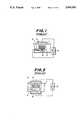
- FIG. 7is a schematic view illustrating the construction of another embodiment of the hyperthermia apparatus according to the invention.
- FIG. 8is a schematic view showing the detailed construction of the apparatus shown in FIG. 7;
- FIGS. 9 and 10are cross sectional views showing two embodiments of a heat exchanger of the apparatus shown in FIG. 8;
- FIG. 11is a schematic view illustrating still another embodiment of the hyperthermia apparatus according to the invention in which an electrode is divided into a plurality of sections;
- FIG. 12is a schematic view depicting a modified embodiment of the hyperthermia apparatus of FIG. 11.
- FIG. 3is a schematic view showing an embodiment of the hyperthermia apparatus according to the invention.
- a single inside-body electrode 11hereinafter referred to as first electrode
- two outside-body electrodes 12 and 13referred to as second and third electrodes, respectively
- the selection switch 14serves to connect a first combination of the first and second electrodes 11 and 12 or a second combination of the second and third electrodes 12 and 13 to a high frequency power supply source 15 so that an electric field of a Radio Frequency can be applied across the electrodes 11 and 12 or the electrodes 12 and 13.
- the first electrode 11is arranged at a distal end of a flexible thin tube 19 and is inserted into a cavity 2 of a patient's body 1 at such a position that the first electrode is faced to a cancer 3.
- the apparatusis utilized to destroy the cancer 3 formed in an esophagus 2a.
- the first electrode 11is surrounded by a balloon 16.
- an electrically conductive liquid mediumsuch as physiological saline solution is circulated via tubes 20a inserted into the insertion tube 19 and a heat exchanger (not shown to) heat or cool a cavity wall against which the balloon 16 is urged.
- the second electrode 12is placed on a front surface of the body 1 such that it is faced to the first electrode 11 via the cancer 3. Further, the third electrode 13 is arranged on a rear surface of the body 1 at such a position that it is faced to the second electrode 12. Similar to the first electrode 11, the second and third electrodes 12 and 13 are surrounded by balloons 17 and 18, respectively. An electrically conductive liquid medium such as physiological saline solution is circulated through the balloons 17 and 18 by means of tubes 20b and 20c and a heat exchanger (not shown), so that parts of the body 1 contacting the balloons 17 and 18 are cooled. It should be noted that the heating or cooling system for the first electrode 11 and the cooling systems for the second and third electrodes 12 and 13 are electrically isolated from each other as will be explained later.
- the RF power supply device 15has two output termianls, one of which is directly connected to the second electrode 12 and the other of which is connected to a switching contact 14a of the selection switch 14 whose fixed contacts 14b and 14c are connected to the first and third electrodes 11 and 13, respectively. Therefore, in the present embodiment, the second outside-body electrode 12 is always connected to the RF power supply device 15.
- the switching arm of the switch 14When a switching arm of the switch 14 is connected to the fixed contact 14b, the first and second electrodes 11 and 12 are selected and the RF electric field is selectively generated across these electrodes. When the switching arm of the switch 14 is changed to the fixed contact 14c, the second and third electrodes 12 and 13 are selected and the RF electric field is produced thereacross. Therefore, by changing the switching arm periodically, the first pair of electrodes 11, 12 and the second pair of electrodes 12, 13 are alternatively selected.
- the switching arm of the switch 14may be driven manually or automatically in accordance with a program which has been set on the basis of the dimension and position of the cancer 3.
- the application of the RF electric power to the electrodescan be automatically controlled by means of temperature sensors such as thermo-couples arranged on the outer surfaces of the balloons 16 to 18 in such a manner that when sensed temperatures exceed predetermined temperatures, the application of the RF power is interrupted until the sensed temperatures become lower than the predetermined temperatures. In this manner, the cancer 3 can be maintained substantially at the desired temperature.
- the cancer 3can be wholly heated substantially uniformly to a desired temperature at which the malignant tissues are selectively necrosed substantially regardless of the size and position of the cancer and any error in positioning the electrodes.
- the hyperthermia apparatuscan be continuously utilized for a long time period necessary for an optimum thermotherapy.
- FIG. 5is a schematic view illustrating another embodiment of the hyperthermia apparatus according to the invention.
- portions similar to those of the previous embodimentare denoted by the same reference numerals as those used in FIG. 3.
- the present embodimentdiffers from the previous embodiment only in the point that a first inside-body electrode 11 is directly connected to one output of an RF power supply device 15, and second and third outside-body electrodes 12 and 13 are connected to fixed contacts 14b and 14c of a switch 14, whose switching contact is connected to the other output of the power supply device 15.
- the cancer 3 which is formed around the cavity 2can be efficiently heated to a desired temperature. It should be noted that if cancers are existent in cavity wall portions opposing each other, it would be preferable to constitute a mode in which the second and third electrodes are selected.
- two electrodes including at least one outside-body electrodeare selectively connected to the RF power supply device and the high frequency electric field is applied across the selected electrodes, so that the malignant tissues of the cancer can be wholly heated to the desired temperature, while the normal tissues can be effectively prevented from being heated to excessively high temperatures.
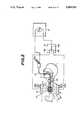
- FIG. 6is a block diagram showing the detailed construction of an embodiment of the RF power supply device 15.
- an RF signal generated from an RF oscillator 21is supplied via high frequency amplifier 22 and impedance matching (IM) circuit 23 to a co-axial cable 24.
- the impedance matching circuit 23serves to attain the impedance matching with respect to the co-axial cable 24 and an output end of the co-axial cable is connected to an interface 25 which is arranged near the patient.
- the interface 25comprises variable impedance matching (VIM) circuit 26, selection switch 14 and connectors 31, 32 and 33 to which connectors the first, second and third electrodes 11, 12 and 13 are connected via condutors, respectively.
- VIPvariable impedance matching
- the electrode selecting operation of the switch 14is controlled by a main controller 34 in accordance with a predetermined program.
- the interface 25further comprises connectors 35, 36 and 37 to which temperature sensors arranged near respective electrodes 11, 12 and 13 are connected via conductors, respectively. Output signals supplied from the temperature sensors via the connectors 35, 36 and 37 are sent to the main controller 34.
- the switch 14may be controlled in accordance with a program which uses the sensed temperatures as parameters.
- phase detector 38for detecting a phase shift of the RF signal and wattmeter 39 of transmission type for measuring incident power and reflected power.
- Outputs of the phase detector 38 and wattmeter 39are supplied to the main controller 34 as well as to an automatic impedance matching controller 40.
- This controller 40supplies a control signal to the variable impedance matching circuit 26 such that the input impedance of the load circuit including two electrodes selected by the switch 14 is matched to the output impedance of the RF power supply device 15 including the co-axial cable 24.
- the high frequency amplifier 22is energized by a power source 41.
- the power source 41is controlled by an ON/OFF controller 42 under the control of the main controller 34 such that the output power from the amplifier 22 is returned ON and OFF. For instance, when the electrodes are switched into or out of the circuit by the switch 14, the RF power is decreased to zero, and when the sensed temperatures increase or above decrease blow the predetermined values, the RF power is switched OFF or ON.
- the reflected power measured by the wattmeter 39is supplied also to an excessive reflection monitor 43.
- the measured reflection poweris compared with a given freference value, and when the reflection power exceeds the reference value, a signal is supplied to an over-reflection display 44 to display the excessive reflection of the RF power.
- the monitor 43supplies the signal also to the main controller 34 and a forcedly OFF controller 45, and the output power of the high frequency amplifier 22 is made OFF via the ON/OFF controller 42 and power source 41. Therefore, even if there occurs sudden impedance mismatching due to the disconnection of one or more electrodes from relevant connectors 31, 32 and 33, the excessive large reflection power which might damage the apparatus could never be produced.
- the amplification factor of the high frequency amplifier 22is adjusted by the main controller 34 such that the output power of the amplifier 22 is decreased to a safe low level when the impedance matching becomes worse at a time of switching the electrodes and during the application of the RF power to the electrodes. Then, the automatic impedance matching is carried out at said safe low level, and after the impedance matching has been attained, the output power of the high frequency amplifier 22 is increased to the desired high level. In this manner, the apparatus can be protected against damage due to the impedance mismatching at the start time and during the application of the RF power to the electrodes, and at the same time, the patient is effectively prevented from being subjected to the dangerous electric shock.
- the switching operation of electrodesis effected, but it is also possible to make the output power OFF from the low level or directly from the desired high level without interleaving the low level, and after the electrodes have been switched, the output power is slightly increased to the low level and the impedance matching is effected under this low level. Further, the switching of electrodes may be carried out manually instead of automatically. In this case, it is preferable to provide a manual switch for changing the output power of the high frequency amplifier 22 among the desired high level, safe low level and zero level, and prior to the selection of electrodes, the output power is manually set to the low level or zero level.
- the impedance matchingis carried out automatically or manually under the low output power.
- an indicatorsuch as meter, lamp or buzzer
- the output poweris increased to the high level by operating the manual switch.
- the manual selection switch 14there may be provided a lock mechanism for inhibiting the operation of the switch as long as the high level power is generated from the high frequency amplifier 22.
- a photosensor or contact sensorfor detecting the operation of the manual switch 14, and an alarm for producing an alarm sound or light when the switch is to be operated under the high output condition.
- the output poweris switched into the low or zero level prior to the switching of electrodes, and after the electrodes have been switched, the impedance matching is carried out under the low level power and then the output power is increased to the high level for heating the body. Therefore, the apparatus is effectively protected against damage due to the impedance mismatching and further the patient can be prevented from being subjected to the electric shock, so that the thermotherapy can be performed safely.
- inside-body electrode and two outside-body electrodesthere are arranged one inside-body electrode and two outside-body electrodes, but the present invention is not restricted to such a construction.
- a plurality of inside-body electrodesmay be inserted into the cavity of a patient's body extending in the longitudinal direction thereof and a corresponding number of outside-body electrodes may be arranged on the outer surface of the patient's body.
- the microwave powercan be effectively used instead of the RF power.
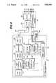
- FIG. 7is a schematic view illustrating the construction of another embodiment of the hyperthermia apparatus according to the invention
- FIG. 8is a view showing its fluid system in detail.
- the hyperthermia apparatuscomprises an RF supply unit 51 and a cooling unit 52.
- the RF power supply unit 51is coupled with an electrode of an inside-body applicator 54 by means of an RF cable 53 as well as to electrodes of two outside-body applicators 56a and 56b via RF cables 55a and 55b, respectively.
- the cooling unit 52is connected to a balloon of the inside-body applicator 54 through water supply and discharge pipes 57 and 58 as well as to balloons of the outside-body applicators 56a and 56b by means of water supply and discharge pipes 59a, 59b, 59c and 60a, 60b, 60c.
- the inside-body applicator 54has a suitable size, shape and construction for easy insertion into the cavity of the body 61.
- the inside-body applicator 54comprises a flexible rod 62 made of electrically insulating material, an inside-body electrode 63 arranged on a distal end of the rod and a balloon 64 made of electrically insulating material, the electrode being wholly surrounded by the balloon.
- a duct 65which is connected to the electrically insulating water supply pipe 57 and a duct 66 which is coupled with the water discharge pipe 58 made of electrically insulating material, these ducts being open within the balloon 64.
- a conductive strip 67which is connected to the RF cable 53 and extends up to the electrode 63.
- TMtemperature measuring device
- the two outside-body applicators 56a and 56bhave the same construction and comprise outside-body electrodes 71a and 71b connected the RF cables 55a and 55b, and balloons 72a, 72b made of electrically insulating material, the electrodes being separated from the body 61 by the balloons.
- To the balloon 72aare connected water supply and discharge pipes 59b and 60b, and to the balloon 72b are coupled water supply and discharge pipes 59c and 60c, said pipes being made of electrically insulating material.
- thermocouples 73a and 73bwhich are connected via conductors 74a and 74b to a temperature measuring circuit 75 provided in the RF power supply unit 51.
- the temperature measuring circuits 70 and 75detect temperatures at positions of the applicators 54, 56a and 56b, and supply signals to a power source controller 76 which then supplies a control signal to an RF signal source 77a.
- the output power of the RF signal generator 77ais supplied to electrodes via a selection switch 77b.
- the cooling unit 52comprises a heating/cooling device 78 and a heat exchanger 79 connected thereto, so that a liquid medium 80, for instance, water heated or cooled by the heating/cooling device is circulated through the heat exchanger 79.
- a liquid medium 80for instance, water heated or cooled by the heating/cooling device is circulated through the heat exchanger 79.
- the heat exchanger 79there is arranged a coiled pipe 81 which is connected to the supply and discharge pipes 57 and 58.
- the coiled pipe 81is made of electrically insulating material.
- a roller pump 82for circulating an electrically conductive medium, i.e.
- the heat exchanger 79the heat exchange is carried out between the water 80 and the medium 83 flowing through the coiled pipe 81, and thus the temperature of the medium 83 is controlled.
- the liquid medium 83 circulated through the balloon 64 of the inside-body applicator 54serves not only to cool the living body, but also to heat the body. In the thermotherapy, it is necessary to heat the malignant tissues of cancer to a high temperature higher than 42° to 43° C.
- thermotherapyit is preferable to heat the body with the aid of the medium 83.
- the medium 83In order to avoid the death or damage of normal tissues, it is necessary to keep the normal tissues at temperatures below 43° to 44° C., so that the medium 83 must have the function to cool the body. In this manner, the temperature of the medium 83 has to be controlled in accordance with temperatures of the part of the body at which the applicator 54 is arranged.
- the outside-body applicators 56a and 56bmust have the function for cooling the body, so that a cooling device 84 and a heat exchanger 85 coupled therewith are provided in the cooling unit 52.
- a cooling device 84 and a heat exchanger 85coupled therewith are provided in the cooling unit 52.
- the heat exchanger 85there is arranged a coiled pipe 86 connected to the pipes 59a and 60a made of electrically insulating material.
- a roller pump 87for circulating a cooling medium 88 made of saline solution through pump 87--pipes 59a, 59b--balloon 72a--pipes 60b, 60a--coiled pipe 86--pipe 59a--pump 87 as well as pump 87--pipes 59a, 59c--balloon 72b--pipes 60c, 60a--coiled pipe 86--pipe 59--pump 87.
- the cooling device 84is controlled by the temperature measuring circuit 75 to adjust the temperature of the saline solution 88.
- the saline solutions 83 and 88circulate through the balloons 64 and 72a, 72b and the waters 80 and 89 circulate via the heating/cooling devices 78 and 84 such that these devices are electrically isolated from each other, and therefore the saline solutions 83 and 88 are never short-circuited although the heating/cooling devices 78 and 84 are connected to the common power supply line.
- the roller pumps 82 and 87do not contact the saline solutions 83 and 88 and feed the solutions by squeezing the flexible tubes, so that although motors for rotating rollers of the roller pumps are commonly connected to the same power supply line, the solutions are not short-circuited at all through the roller pumps.
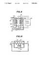
- FIG. 9is a partially cross sectional schematic view showing another embodiment of the cooling unit for controlling the temperature of the liquid mediums.
- the cooling unitcomprises a cooling device 84 and a heat exchanger 85 coupled therewith.
- the heat exchanger 85there are arranged two coiled pipes 86a and 86b, one being coupled with one outside-body applicator via pipes 90a, 91a and the other being connected to the other outside-body applicator by means of pipes 90b and 91b.
- the saline solutions circulating through the outside-body applicator balloonscan be completely isolated.
- FIG. 10shows another embodiment of the cooling unit according to the invention.
- a Peltier element 93is provided on an outer surface of a housing of a heat exchanger 92 and temperature inside the housing is adjusted by supplying the electric power to the Peltier element.
- a coiled pipe 94which is communicated to the balloon of the applicator by means of pipes 95 and 96.
- the liquid mediums which are circulated through the balloons of the applicatorsare completely isolated from each other, and thus any accidental short-circuit can be effectively protected and the apparatus can be used safely.
- the mediumcan be formed by the electrically conductive liquid such as the saline solution, it is possible to apply the high frequency field to the body efficiently and only the malignant tissues can be locally heated to the desired temperature.
- FIG. 11is a schematic view showing still another embodiment of the hyperthermia apparatus according to the invention.
- the apparatuscomprises an outside-body electrode 102 arranged on an outer surface of a patient body 101, and an inside-body electrode 103 inserted into a cavity 104 of the body 101.
- the inside-body electrode 103is arranged at a distal end of a flexible insertion member 105 which can be easily inserted into the cavity 104 of the body.
- the electrodes 102 and 103are divided into a corresponding number of electrode sections a ⁇ i which are arranged along lines. That is to say, the electrode sections a ⁇ i of the inside-body electrode 103 are aligned in the longitudinal direction of the insertion member 105.
- each electrode section of the inside-body electrode 103is connected respective conductors 106 which are connected to selection contacts 115 (a ⁇ i) of a first rotary switch 107 whose switching arm 112 is connected to an impedance matching circuit 108.
- each electrode section of the outside-body electrode 102is connected via conductors 109 to respective selection contacts 116 (a ⁇ i) of a second rotary switch 110 whose switching arm 113 is also connected to the impedance matching circuit 108.
- the impedance matching circuit 108is connected to a high frequency oscillator 117.
- the switching arms 112 and 113 of the first and second rotary switches 107 and 110are rotated by a switch driver 114 in conjunction with each other at a given speed. Therefore, the corresponding electrode sections a ⁇ i of the electrodes 102 and 103 are successively energized with the high frequency power supplied from the oscillator 111 at a given repetition period.
- the insertion member 105is inserted into the cavity 104 of the body 101 such that the inside-body electrode 103 is positioned to face to a cancer 117.
- the outside-body electrode 102is arranged and fixed on the outer surface of the body 101 such that the cancer is sandwiched between the electrodes 102 and 103. That is to say, the electrode sections a ⁇ i of the outside-body electrode 102 are faced to corresponding electrode sections a ⁇ i of the inside-body electrode 103 in a symmetrical manner, while the center point of symmetry is positioned at a center of the cancer 117.
- the switching arms 112 and 113 of the first and second rotary switches 107 and 110are rotated in conjunction with each other by means of the switch driver 114 so that corresponding switching contacts a ⁇ i are successively connected to the switching arms at the constant period.
- a first pair of electrode sections a, a; a second pair of electrode sections b, b; a third pair of electrode sections c, c; . . . of the outside-body and inside-body electrodes 102 and 103are successively energized with the high frequency power supplied from the high frequency oscillator 111. Therefore, across electrode sections of successive pairs are generated the high frequency electric fields as shown by broken lines in FIG. 11, and the cancer 117 is locally heated to a desired high temperature.
- portions of the body 101 near the electrodes 102 and 103are not continuously subjected to the strong electric field so that these portions are not heated to higher temperatures, while the cancer 117 is always exposed to the electric fields and is heated to the high temperature. Therefore, it is no longer necessary to provide a larger cooling unit for cooling the electrode sections, so that the electrode sections a ⁇ i can be simple in construction and small in size. Further, the inside-body electrode 103 to be inserted into the cavity 104 of the body 101 can be made very small and the patient can be protected from pain.
- FIG. 12is a schematic view illustrating still another embodiment of the hyperthermia apparatus according to the invention. Similar to the previous embodiment illustrated in FIG. 12, an outside-body electrode 102 is divided into a plurality of electrode sections a ⁇ i, but an inside-body electrode 125 is arranged movably in an insertion member 105 in its longitudinal direction. In the insertion member 105 is also inserted a wire 126 whose one end is connected to the inside-body electrode 125. The other end of the wire 126 is wound around a pulley 127 which is connected to a stepping motor 128.
- a ⁇ i of the outside-body electrode 102are connected via respective conductors 129 to switching contacts of a rotary switch 130 whose switching arm 132 is connected to a high frequency oscillator 131.
- the switching arm 132 of the rotary switch 130is coupled with a second stepping motor 133.
- the first and second stepping motors 128 and 133are driven by a motor driver 134 in conjunction with each other.
- the wire 136 inserted into the insertion member 105serves also as an electric conductor for supplying the high frequency power from the oscillator 131 to the inside-body electrode 125.
- the high frequency power from the oscillator 131is supplied by means of the wire 126 and rotary switch 130 to the outside-body electrode 102 and inside-body electrode 125.
- the high frequency poweris successively supplied for a given period by means of the rotary switch 130 which is driven by the second stepping motor 133.
- the pulley 127is rotated by the first stepping motor 128 to wind or rewind the wire 126, so that the inside-body electrode 125 is moved along the insertion member 105 in such a manner that lines connecting the inside-body electrode 125 and successively energized electrode sections a ⁇ i of the outside-body electrode 102 cross each other at a point within the cancer 117 of the patient 101. Therefore, the high frequency electric field is always applied to the cancer 117 and the cancer is locally heated to the desired temperature, while temperatures of portions of the body near the electrodes can be effectively prevented from being heated excessively.
- the single inside-body electrode 125is moved such that it situates at positions which are point-symmetrical with respect to the electrode sections a ⁇ i of the outside-body electrode 102, and thus the single inside-body electrode 125 serves substantially as a plurality of electrode sections.
- the outside-body electrodeis divided into a plurality of electrode sections and the inside-body electrode is also divided into a plurality of electrode-sections or is moved along the insertion member, and the high frequency power is supplied across the successive electrode sections of the outside-body electrode and inside-body electrode or across the successive electrode sections of the outside-body electrode and the movable inside-body electrode such that the high frequency electric fields are concentrated at the cancer, and therefore the malignant tissues can be locally heated to the desired high temperature.
- the electric power of high frequencyis selectively supplied to two electrodes by means of the two contact switches and rotary switch, but according to the invention, the electrode selecting means may be constructed by semiconductor switches. Further, there may be arranged a plurality of high frequency power supply sources each corresponding to respective electrodes and the operation of these power supply sources may be switched. Moreover, in the embodiment illustrated in FIG. 11, the number of electrode sections of the inside-body electrode may be smaller than that of the outside-body electrode.
Landscapes
- Health & Medical Sciences (AREA)
- Radiology & Medical Imaging (AREA)
- Engineering & Computer Science (AREA)
- Biomedical Technology (AREA)
- Nuclear Medicine, Radiotherapy & Molecular Imaging (AREA)
- Life Sciences & Earth Sciences (AREA)
- Animal Behavior & Ethology (AREA)
- General Health & Medical Sciences (AREA)
- Public Health (AREA)
- Veterinary Medicine (AREA)
- Neurosurgery (AREA)
- Neurology (AREA)
- Electrotherapy Devices (AREA)
Abstract
Description
Claims (11)
Applications Claiming Priority (10)
| Application Number | Priority Date | Filing Date | Title |
|---|---|---|---|
| JP7646187AJPS63242275A (en) | 1987-03-31 | 1987-03-31 | Hyperthermia apparatus |
| JP62-76460 | 1987-03-31 | ||
| JP62-76463 | 1987-03-31 | ||
| JP7646387AJPH078298B2 (en) | 1987-03-31 | 1987-03-31 | Hyperthermia device |
| JP7646087AJPS63242274A (en) | 1987-03-31 | 1987-03-31 | Hyperthermia apparatus |
| JP62-76461 | 1987-03-31 | ||
| JP8466787AJPH0728926B2 (en) | 1987-04-08 | 1987-04-08 | Hyperthermia device |
| JP62-84667 | 1987-04-08 | ||
| JP62-94482 | 1987-04-17 | ||
| JP9448287AJPH0698195B2 (en) | 1987-04-17 | 1987-04-17 | Hyperthermia device |
Publications (1)
| Publication Number | Publication Date |
|---|---|
| US5003991Atrue US5003991A (en) | 1991-04-02 |
Family
ID=27524624
Family Applications (1)
| Application Number | Title | Priority Date | Filing Date |
|---|---|---|---|
| US07/172,554Expired - LifetimeUS5003991A (en) | 1987-03-31 | 1988-03-24 | Hyperthermia apparatus |
Country Status (1)
| Country | Link |
|---|---|
| US (1) | US5003991A (en) |
Cited By (142)
| Publication number | Priority date | Publication date | Assignee | Title |
|---|---|---|---|---|
| WO1992007621A1 (en)* | 1990-11-05 | 1992-05-14 | Bsd Medical Corporation | Urethral inserted applicator for prostate hyperthermia |
| US5249585A (en)* | 1988-07-28 | 1993-10-05 | Bsd Medical Corporation | Urethral inserted applicator for prostate hyperthermia |
| US5277201A (en)* | 1992-05-01 | 1994-01-11 | Vesta Medical, Inc. | Endometrial ablation apparatus and method |
| US5330518A (en)* | 1992-03-06 | 1994-07-19 | Urologix, Inc. | Method for treating interstitial tissue associated with microwave thermal therapy |
| US5413588A (en)* | 1992-03-06 | 1995-05-09 | Urologix, Inc. | Device and method for asymmetrical thermal therapy with helical dipole microwave antenna |
| US5417713A (en)* | 1993-02-09 | 1995-05-23 | Leonard Bloom | Transesophageal defibrillating system |
| US5421819A (en) | 1992-08-12 | 1995-06-06 | Vidamed, Inc. | Medical probe device |
| US5433740A (en)* | 1991-04-25 | 1995-07-18 | Olympus Optical Co., Ltd. | Method and apparatus for thermotherapy |
| US5435805A (en) | 1992-08-12 | 1995-07-25 | Vidamed, Inc. | Medical probe device with optical viewing capability |
| US5443470A (en)* | 1992-05-01 | 1995-08-22 | Vesta Medical, Inc. | Method and apparatus for endometrial ablation |
| US5456662A (en) | 1993-02-02 | 1995-10-10 | Edwards; Stuart D. | Method for reducing snoring by RF ablation of the uvula |
| US5464437A (en)* | 1993-07-08 | 1995-11-07 | Urologix, Inc. | Benign prostatic hyperplasia treatment catheter with urethral cooling |
| US5470308A (en) | 1992-08-12 | 1995-11-28 | Vidamed, Inc. | Medical probe with biopsy stylet |
| US5474071A (en)* | 1991-03-05 | 1995-12-12 | Technomed Medical Systems | Therapeutic endo-rectal probe and apparatus constituting an application thereof for destroying cancer tissue, in particular of the prostate, and preferably in combination with an imaging endo-cavitary-probe |
| US5514131A (en) | 1992-08-12 | 1996-05-07 | Stuart D. Edwards | Method for the ablation treatment of the uvula |
| WO1996016606A1 (en)* | 1994-12-01 | 1996-06-06 | Vidamed, Inc. | Transurethral needle delivery device with cystoscope and method for treatment of urinary incontinence |
| US5536240A (en)* | 1992-08-12 | 1996-07-16 | Vidamed, Inc. | Medical probe device and method |
| US5540654A (en)* | 1994-09-02 | 1996-07-30 | North Carolina State University | Iontophoretic electrode |
| US5542915A (en) | 1992-08-12 | 1996-08-06 | Vidamed, Inc. | Thermal mapping catheter with ultrasound probe |
| US5556377A (en) | 1992-08-12 | 1996-09-17 | Vidamed, Inc. | Medical probe apparatus with laser and/or microwave monolithic integrated circuit probe |
| US5562720A (en)* | 1992-05-01 | 1996-10-08 | Vesta Medical, Inc. | Bipolar/monopolar endometrial ablation device and method |
| US5599346A (en)* | 1993-11-08 | 1997-02-04 | Zomed International, Inc. | RF treatment system |
| US5599295A (en) | 1992-08-12 | 1997-02-04 | Vidamed, Inc. | Medical probe apparatus with enhanced RF, resistance heating, and microwave ablation capabilities |
| US5630794A (en) | 1992-08-12 | 1997-05-20 | Vidamed, Inc. | Catheter tip and method of manufacturing |
| US5634470A (en)* | 1994-06-29 | 1997-06-03 | Baxter International Inc. | System and method for monitoring and controlling the temperature of a catheter-mounted heater |
| US5672153A (en) | 1992-08-12 | 1997-09-30 | Vidamed, Inc. | Medical probe device and method |
| US5672174A (en)* | 1995-08-15 | 1997-09-30 | Rita Medical Systems, Inc. | Multiple antenna ablation apparatus and method |
| US5672173A (en)* | 1995-08-15 | 1997-09-30 | Rita Medical Systems, Inc. | Multiple antenna ablation apparatus and method |
| WO1997035639A1 (en)* | 1996-03-26 | 1997-10-02 | Urologix, Inc. | Voltage controlled variable tuning antenna |
| US5683384A (en)* | 1993-11-08 | 1997-11-04 | Zomed | Multiple antenna ablation apparatus |
| US5720719A (en) | 1992-08-12 | 1998-02-24 | Vidamed, Inc. | Ablative catheter with conformable body |
| US5728143A (en)* | 1995-08-15 | 1998-03-17 | Rita Medical Systems, Inc. | Multiple antenna ablation apparatus and method |
| US5735847A (en)* | 1995-08-15 | 1998-04-07 | Zomed International, Inc. | Multiple antenna ablation apparatus and method with cooling element |
| US5782827A (en)* | 1995-08-15 | 1998-07-21 | Rita Medical Systems, Inc. | Multiple antenna ablation apparatus and method with multiple sensor feedback |
| US5800486A (en)* | 1996-06-17 | 1998-09-01 | Urologix, Inc. | Device for transurethral thermal therapy with cooling balloon |
| US5810804A (en)* | 1995-08-15 | 1998-09-22 | Rita Medical Systems | Multiple antenna ablation apparatus and method with cooling element |
| US5843144A (en)* | 1995-06-26 | 1998-12-01 | Urologix, Inc. | Method for treating benign prostatic hyperplasia with thermal therapy |
| US5861021A (en)* | 1996-06-17 | 1999-01-19 | Urologix Inc | Microwave thermal therapy of cardiac tissue |
| US5863290A (en)* | 1995-08-15 | 1999-01-26 | Rita Medical Systems | Multiple antenna ablation apparatus and method |
| US5871524A (en)* | 1995-05-05 | 1999-02-16 | Thermage, Inc. | Apparatus for controlled contraction of collagen tissue |
| US5886576A (en)* | 1996-10-16 | 1999-03-23 | Baxter International Inc. | Electrical power amplifier for continuous cardiac output monitoring |
| US5913855A (en)* | 1995-08-15 | 1999-06-22 | Rita Medical Systems, Inc. | Multiple antenna ablation apparatus and method |
| US5919219A (en)* | 1995-05-05 | 1999-07-06 | Thermage, Inc. | Method for controlled contraction of collagen tissue using RF energy |
| US5925042A (en)* | 1995-08-15 | 1999-07-20 | Rita Medical Systems, Inc. | Multiple antenna ablation apparatus and method |
| US5928229A (en)* | 1993-11-08 | 1999-07-27 | Rita Medical Systems, Inc. | Tumor ablation apparatus |
| US5948011A (en)* | 1995-05-05 | 1999-09-07 | Thermage, Inc. | Method for controlled contraction of collagen tissue via non-continuous energy delivery |
| US5951547A (en)* | 1995-08-15 | 1999-09-14 | Rita Medical Systems, Inc. | Multiple antenna ablation apparatus and method |
| US5980517A (en)* | 1995-08-15 | 1999-11-09 | Rita Medical Systems, Inc. | Cell necrosis apparatus |
| US6035238A (en)* | 1997-08-13 | 2000-03-07 | Surx, Inc. | Noninvasive devices, methods, and systems for shrinking of tissues |
| US6059780A (en)* | 1995-08-15 | 2000-05-09 | Rita Medical Systems, Inc. | Multiple antenna ablation apparatus and method with cooling element |
| US6071280A (en)* | 1993-11-08 | 2000-06-06 | Rita Medical Systems, Inc. | Multiple electrode ablation apparatus |
| US6080150A (en)* | 1995-08-15 | 2000-06-27 | Rita Medical Systems, Inc. | Cell necrosis apparatus |
| US6086581A (en)* | 1992-09-29 | 2000-07-11 | Ep Technologies, Inc. | Large surface cardiac ablation catheter that assumes a low profile during introduction into the heart |
| US6090105A (en)* | 1995-08-15 | 2000-07-18 | Rita Medical Systems, Inc. | Multiple electrode ablation apparatus and method |
| US6132425A (en)* | 1995-08-15 | 2000-10-17 | Gough; Edward J. | Cell necrosis apparatus |
| US6216704B1 (en) | 1997-08-13 | 2001-04-17 | Surx, Inc. | Noninvasive devices, methods, and systems for shrinking of tissues |
| US6350276B1 (en) | 1996-01-05 | 2002-02-26 | Thermage, Inc. | Tissue remodeling apparatus containing cooling fluid |
| US6383162B1 (en) | 1999-11-12 | 2002-05-07 | Paul H. Sugarbaker | Apparatus and method for abdomino-pelvic chemotherapy perfusion and lavage |
| US6425912B1 (en) | 1995-05-05 | 2002-07-30 | Thermage, Inc. | Method and apparatus for modifying skin surface and soft tissue structure |
| US6430446B1 (en) | 1995-05-05 | 2002-08-06 | Thermage, Inc. | Apparatus for tissue remodeling |
| US6475213B1 (en) | 1996-01-19 | 2002-11-05 | Ep Technologies, Inc. | Method of ablating body tissue |
| US6480746B1 (en) | 1997-08-13 | 2002-11-12 | Surx, Inc. | Noninvasive devices, methods, and systems for shrinking of tissues |
| US20020198570A1 (en)* | 1997-08-26 | 2002-12-26 | Puskas John D. | Apparatus for indirectly stimulating the vagus nerve with an electrical field |
| US20030178032A1 (en)* | 1997-08-13 | 2003-09-25 | Surx, Inc. | Noninvasive devices, methods, and systems for shrinking of tissues |
| US20030199866A1 (en)* | 1996-01-05 | 2003-10-23 | Stern Roger A. | Method and kit for treatment of tissue |
| US6640138B1 (en) | 2000-08-04 | 2003-10-28 | Thermatrx, Inc. | Apparatus and method for heat treatment of tissue |
| US20030212393A1 (en)* | 1996-01-05 | 2003-11-13 | Knowlton Edward W. | Handpiece with RF electrode and non-volatile memory |
| EP0837712A4 (en)* | 1995-06-07 | 2003-11-26 | Heartport Inc | Devices and methods for port-access multivessel coronary artery bypass surgery |
| US20030220635A1 (en)* | 1996-01-05 | 2003-11-27 | Knowlton Edward W. | Method for treating skin and underlying tissue |
| US20040000316A1 (en)* | 1996-01-05 | 2004-01-01 | Knowlton Edward W. | Methods for creating tissue effect utilizing electromagnetic energy and a reverse thermal gradient |
| US20040002705A1 (en)* | 1996-01-05 | 2004-01-01 | Knowlton Edward W. | Methods for creating tissue effect utilizing electromagnetic energy and a reverse thermal gradient |
| US20040002704A1 (en)* | 1996-01-05 | 2004-01-01 | Knowlton Edward W. | Treatment apparatus with electromagnetic energy delivery device and non-volatile memory |
| US20040024422A1 (en)* | 2000-09-26 | 2004-02-05 | Hill Michael R.S. | Method and system for sensing cardiac contractions during a medical procedure |
| US6689127B1 (en) | 1995-08-15 | 2004-02-10 | Rita Medical Systems | Multiple antenna ablation apparatus and method with multiple sensor feedback |
| US20040030332A1 (en)* | 1996-01-05 | 2004-02-12 | Knowlton Edward W. | Handpiece with electrode and non-volatile memory |
| US20040034346A1 (en)* | 1996-01-05 | 2004-02-19 | Stern Roger A. | RF device with thermo-electric cooler |
| US20040111118A1 (en)* | 2000-09-26 | 2004-06-10 | Hill Michael R.S. | Method and system for spinal cord stimulation prior to and during a medical procedure |
| US20040172075A1 (en)* | 1996-04-30 | 2004-09-02 | Shafer Lisa L. | Method and system for vagal nerve stimulation with multi-site cardiac pacing |
| US20040186517A1 (en)* | 1996-04-30 | 2004-09-23 | Hill Michael R.S. | Method and system for nerve stimulation prior to and during a medical procedure |
| US20040199209A1 (en)* | 2003-04-07 | 2004-10-07 | Hill Michael R.S. | Method and system for delivery of vasoactive drugs to the heart prior to and during a medical procedure |
| US20040206365A1 (en)* | 2003-03-31 | 2004-10-21 | Knowlton Edward Wells | Method for treatment of tissue |
| WO2004089466A1 (en)* | 2003-04-10 | 2004-10-21 | Bonsegna, Pier, Luigi, Maria | Apparatus for non-destructive hyperthermia therapy |
| US20050096707A1 (en)* | 2000-09-26 | 2005-05-05 | Medtronic, Inc. | Method and system for monitoring and controlling systemic and pulmonary circulation during a medical procedure |
| US20050131469A1 (en)* | 2003-12-16 | 2005-06-16 | Leonard Bloom | Hemodynamic optimization system for biventricular implants |
| US20050149013A1 (en)* | 2000-08-09 | 2005-07-07 | Lee Bruce B. | Gynecological ablation procedure and system |
| US6939346B2 (en) | 1999-04-21 | 2005-09-06 | Oratec Interventions, Inc. | Method and apparatus for controlling a temperature-controlled probe |
| US6958062B1 (en) | 1993-11-08 | 2005-10-25 | Rita Medical Systems, Inc. | Multiple antenna ablation apparatus and method |
| US20050288662A1 (en)* | 2004-06-23 | 2005-12-29 | Uchida Andy H | Electrosurgical generator |
| US7004942B2 (en) | 1998-01-14 | 2006-02-28 | Solarant Medical, Inc. | Ribbed electrodes and methods for their use |
| EP1487534A4 (en)* | 2002-02-27 | 2006-03-22 | Medivance Inc | Temperature control pads with integral electrodes |
| US7022121B2 (en) | 1999-03-09 | 2006-04-04 | Thermage, Inc. | Handpiece for treatment of tissue |
| US20060167533A1 (en)* | 2005-01-21 | 2006-07-27 | Solarant Medical, Inc. | Endo-pelvic fascia penetrating heating systems and methods for incontinence treatment |
| US7089064B2 (en) | 1998-05-08 | 2006-08-08 | Ams Research Corporation | Therapeutic prostatic thermotherapy |
| US7141049B2 (en) | 1999-03-09 | 2006-11-28 | Thermage, Inc. | Handpiece for treatment of tissue |
| US20060293649A1 (en)* | 2005-06-22 | 2006-12-28 | Lorang Douglas M | Electrosurgical power control |
| US20070006215A1 (en)* | 2005-07-01 | 2007-01-04 | Gordon Epstein | Anchored RF ablation device for the destruction of tissue masses |
| US20070016183A1 (en)* | 2005-07-01 | 2007-01-18 | Bruce Lee | Radio frequency ablation device for the destruction of tissue masses |
| US7225019B2 (en) | 1996-04-30 | 2007-05-29 | Medtronic, Inc. | Method and system for nerve stimulation and cardiac sensing prior to and during a medical procedure |
| US20080045939A1 (en)* | 2000-08-09 | 2008-02-21 | Halt Medical, Inc. | Gynecological ablation system with insufflation assisted imaging |
| US7452358B2 (en) | 1996-01-05 | 2008-11-18 | Thermage, Inc. | RF electrode assembly for handpiece |
| US20090054892A1 (en)* | 2004-02-02 | 2009-02-26 | Rioux Robert F | System and method for performing ablation using an expandable member |
| US7510555B2 (en) | 2004-05-07 | 2009-03-31 | Therm Med, Llc | Enhanced systems and methods for RF-induced hyperthermia |
| US20090138011A1 (en)* | 2007-03-13 | 2009-05-28 | Gordon Epstein | Intermittent ablation rf driving for moderating return electrode temperature |
| US20090157067A1 (en)* | 2007-12-17 | 2009-06-18 | Thermage, Inc. | Method and apparatus for digital signal processing for radio frequency surgery measurements |
| US20090187183A1 (en)* | 2007-03-13 | 2009-07-23 | Gordon Epstein | Temperature responsive ablation rf driving for moderating return electrode temperature |
| US20090187182A1 (en)* | 2007-11-14 | 2009-07-23 | Gordon Epstein | Rf ablation device with jam-preventing electrical coupling member |
| US20090259274A1 (en)* | 2008-04-10 | 2009-10-15 | Electrocore, Inc. | Methods And Apparatus For Electrical Treatment Using Balloon And Electrode |
| US7627381B2 (en) | 2004-05-07 | 2009-12-01 | Therm Med, Llc | Systems and methods for combined RF-induced hyperthermia and radioimmunotherapy |
| US20090294300A1 (en)* | 2006-11-13 | 2009-12-03 | Kc Energy, Llc | Rf systems and methods for processing salt water |
| US20100004708A1 (en)* | 1996-04-30 | 2010-01-07 | Medtronic, Inc. | Method and system for nerve stimulation and cardiac sensing prior to and during a medical procedure |
| US20100160996A1 (en)* | 2008-12-18 | 2010-06-24 | Electrocore, Inc. | Methods and apparatus for electrical stimulation treatment using esophageal balloon and electrode |
| US7840278B1 (en) | 1999-06-25 | 2010-11-23 | Puskas John D | Devices and methods for vagus nerve stimulation |
| ITFI20100102A1 (en)* | 2010-05-12 | 2011-11-13 | Easytech S R L | ELECTRODE COOLED FOR APPLIANCES WITH CAPACITIVE / RESISTIVE ELECTROMAGNETIC HEATING. |
| US8251991B2 (en) | 2007-11-14 | 2012-08-28 | Halt Medical Inc. | Anchored RF ablation device for the destruction of tissue masses |
| US8406868B2 (en) | 2010-04-29 | 2013-03-26 | Medtronic, Inc. | Therapy using perturbation and effect of physiological systems |
| WO2013106036A3 (en)* | 2011-04-08 | 2013-10-17 | Domain Surgical, Inc. | Impedance matching circuit |
| US8620425B2 (en) | 2010-04-29 | 2013-12-31 | Medtronic, Inc. | Nerve signal differentiation in cardiac therapy |
| US8617151B2 (en) | 2009-04-17 | 2013-12-31 | Domain Surgical, Inc. | System and method of controlling power delivery to a surgical instrument |
| US8639327B2 (en) | 2010-04-29 | 2014-01-28 | Medtronic, Inc. | Nerve signal differentiation in cardiac therapy |
| US8682449B2 (en) | 2008-04-10 | 2014-03-25 | ElectroCore, LLC | Methods and apparatus for transcranial stimulation |
| US8706223B2 (en) | 2011-01-19 | 2014-04-22 | Medtronic, Inc. | Preventative vagal stimulation |
| US8718763B2 (en) | 2011-01-19 | 2014-05-06 | Medtronic, Inc. | Vagal stimulation |
| US8725259B2 (en) | 2011-01-19 | 2014-05-13 | Medtronic, Inc. | Vagal stimulation |
| US8781582B2 (en) | 2011-01-19 | 2014-07-15 | Medtronic, Inc. | Vagal stimulation |
| US8781583B2 (en) | 2011-01-19 | 2014-07-15 | Medtronic, Inc. | Vagal stimulation |
| US8858544B2 (en) | 2011-05-16 | 2014-10-14 | Domain Surgical, Inc. | Surgical instrument guide |
| US20140350538A1 (en)* | 2013-05-24 | 2014-11-27 | National Cheng Kung University | Coil-integrated pad assembly and an electromagnetic hyperthermia system including the same |
| US20140378962A1 (en)* | 2013-06-25 | 2014-12-25 | Boston Scientific Scimed, Inc. | Devices and methods for nerve modulation using localized indifferent electrodes |
| US8932279B2 (en) | 2011-04-08 | 2015-01-13 | Domain Surgical, Inc. | System and method for cooling of a heated surgical instrument and/or surgical site and treating tissue |
| US8968284B2 (en) | 2000-10-02 | 2015-03-03 | Verathon Inc. | Apparatus and methods for treating female urinary incontinence |
| US9023031B2 (en) | 1997-08-13 | 2015-05-05 | Verathon Inc. | Noninvasive devices, methods, and systems for modifying tissues |
| US9078655B2 (en) | 2009-04-17 | 2015-07-14 | Domain Surgical, Inc. | Heated balloon catheter |
| US9107666B2 (en) | 2009-04-17 | 2015-08-18 | Domain Surgical, Inc. | Thermal resecting loop |
| US9131977B2 (en) | 2009-04-17 | 2015-09-15 | Domain Surgical, Inc. | Layered ferromagnetic coated conductor thermal surgical tool |
| US9220557B2 (en) | 2009-04-17 | 2015-12-29 | Domain Surgical, Inc. | Thermal surgical tool |
| US9265556B2 (en) | 2009-04-17 | 2016-02-23 | Domain Surgical, Inc. | Thermally adjustable surgical tool, balloon catheters and sculpting of biologic materials |
| US9526558B2 (en) | 2011-09-13 | 2016-12-27 | Domain Surgical, Inc. | Sealing and/or cutting instrument |
| US9572695B2 (en) | 2009-08-24 | 2017-02-21 | New Phase Ltd | Phase-change and shape-change materials |
| US9872902B2 (en) | 2014-11-25 | 2018-01-23 | New Phase Ltd. | Phase-change nanoparticle |
| US20190117991A1 (en)* | 2017-10-19 | 2019-04-25 | Robert Der-Yang Tien | System and method for treating cancer |
| US10357306B2 (en) | 2014-05-14 | 2019-07-23 | Domain Surgical, Inc. | Planar ferromagnetic coated surgical tip and method for making |
| US20250276150A1 (en)* | 2024-01-19 | 2025-09-04 | Robert Sabin | Inhaled internal heat/thermal conduction therapy for esophageal cancer and related esophageal pre-cancerous diseases |
Citations (4)
| Publication number | Priority date | Publication date | Assignee | Title |
|---|---|---|---|---|
| US4140130A (en)* | 1977-05-31 | 1979-02-20 | Storm Iii Frederick K | Electrode structure for radio frequency localized heating of tumor bearing tissue |
| US4285346A (en)* | 1979-03-14 | 1981-08-25 | Harry V. LeVeen | Electrode system |
| US4676258A (en)* | 1983-01-24 | 1987-06-30 | Kureha Kagaku Kogyo Kabushiki Kaisha | Device for hyperthermia |
| US4846196A (en)* | 1986-01-29 | 1989-07-11 | Wiksell Hans O T | Method and device for the hyperthermic treatment of tumors |
- 1988
- 1988-03-24USUS07/172,554patent/US5003991A/ennot_activeExpired - Lifetime
Patent Citations (4)
| Publication number | Priority date | Publication date | Assignee | Title |
|---|---|---|---|---|
| US4140130A (en)* | 1977-05-31 | 1979-02-20 | Storm Iii Frederick K | Electrode structure for radio frequency localized heating of tumor bearing tissue |
| US4285346A (en)* | 1979-03-14 | 1981-08-25 | Harry V. LeVeen | Electrode system |
| US4676258A (en)* | 1983-01-24 | 1987-06-30 | Kureha Kagaku Kogyo Kabushiki Kaisha | Device for hyperthermia |
| US4846196A (en)* | 1986-01-29 | 1989-07-11 | Wiksell Hans O T | Method and device for the hyperthermic treatment of tumors |
Cited By (264)
| Publication number | Priority date | Publication date | Assignee | Title |
|---|---|---|---|---|
| US5249585A (en)* | 1988-07-28 | 1993-10-05 | Bsd Medical Corporation | Urethral inserted applicator for prostate hyperthermia |
| WO1992007621A1 (en)* | 1990-11-05 | 1992-05-14 | Bsd Medical Corporation | Urethral inserted applicator for prostate hyperthermia |
| US5474071A (en)* | 1991-03-05 | 1995-12-12 | Technomed Medical Systems | Therapeutic endo-rectal probe and apparatus constituting an application thereof for destroying cancer tissue, in particular of the prostate, and preferably in combination with an imaging endo-cavitary-probe |
| US5666954A (en)* | 1991-03-05 | 1997-09-16 | Technomed Medical Systems Inserm-Institut National De La Sante Et De La Recherche Medicale | Therapeutic endo-rectal probe, and apparatus constituting an application thereof for destroying cancer tissue, in particular of the prostate, and preferably in combination with an imaging endo-cavitary-probe |
| US5433740A (en)* | 1991-04-25 | 1995-07-18 | Olympus Optical Co., Ltd. | Method and apparatus for thermotherapy |
| US5916241A (en)* | 1992-03-06 | 1999-06-29 | Urologix, Inc. | Device and method for asymmetrical thermal therapy with helical dipole microwave antenna |
| US5916240A (en)* | 1992-03-06 | 1999-06-29 | Urologix, Inc. | Device and method for asymmetrical thermal therapy with helical dipole microwave antenna |
| US5545137A (en)* | 1992-03-06 | 1996-08-13 | Urologix, Inc. | Device for asymmetrical thermal therapy with helical dipole microwave antenna |
| US5755754A (en)* | 1992-03-06 | 1998-05-26 | Urologix, Inc. | Device and method for asymmetrical thermal therapy with helical dipole microwave antenna |
| US5464445A (en)* | 1992-03-06 | 1995-11-07 | Urologix, Inc. | Device and method for asymmetrical thermal therapy with helical dipole microwave antenna |
| US5413588A (en)* | 1992-03-06 | 1995-05-09 | Urologix, Inc. | Device and method for asymmetrical thermal therapy with helical dipole microwave antenna |
| US5330518A (en)* | 1992-03-06 | 1994-07-19 | Urologix, Inc. | Method for treating interstitial tissue associated with microwave thermal therapy |
| US5620480A (en)* | 1992-03-06 | 1997-04-15 | Urologix, Inc. | Method for treating benign prostatic hyperplasia with thermal therapy |
| US6041260A (en)* | 1992-05-01 | 2000-03-21 | Vesta Medical, Inc. | Method and apparatus for endometrial ablation |
| US5443470A (en)* | 1992-05-01 | 1995-08-22 | Vesta Medical, Inc. | Method and apparatus for endometrial ablation |
| US5713942A (en)* | 1992-05-01 | 1998-02-03 | Vesta Medical, Inc. | Body cavity ablation apparatus and model |
| US5277201A (en)* | 1992-05-01 | 1994-01-11 | Vesta Medical, Inc. | Endometrial ablation apparatus and method |
| US5562720A (en)* | 1992-05-01 | 1996-10-08 | Vesta Medical, Inc. | Bipolar/monopolar endometrial ablation device and method |
| US5672153A (en) | 1992-08-12 | 1997-09-30 | Vidamed, Inc. | Medical probe device and method |
| US5421819A (en) | 1992-08-12 | 1995-06-06 | Vidamed, Inc. | Medical probe device |
| US5542915A (en) | 1992-08-12 | 1996-08-06 | Vidamed, Inc. | Thermal mapping catheter with ultrasound probe |
| US5536240A (en)* | 1992-08-12 | 1996-07-16 | Vidamed, Inc. | Medical probe device and method |
| US5554110A (en) | 1992-08-12 | 1996-09-10 | Vidamed, Inc. | Medical ablation apparatus |
| US5556377A (en) | 1992-08-12 | 1996-09-17 | Vidamed, Inc. | Medical probe apparatus with laser and/or microwave monolithic integrated circuit probe |
| US6206847B1 (en) | 1992-08-12 | 2001-03-27 | Vidamed, Inc. | Medical probe device |
| US5435805A (en) | 1992-08-12 | 1995-07-25 | Vidamed, Inc. | Medical probe device with optical viewing capability |
| US5582589A (en)* | 1992-08-12 | 1996-12-10 | Vidamed, Inc. | Medical probe with stylets |
| US5895370A (en) | 1992-08-12 | 1999-04-20 | Vidamed, Inc. | Medical probe (with stylets) device |
| US5591125A (en)* | 1992-08-12 | 1997-01-07 | Vidamed, Inc. | Medical probe with stylets |
| US5599294A (en) | 1992-08-12 | 1997-02-04 | Vidamed, Inc. | Microwave probe device and method |
| US6464661B2 (en) | 1992-08-12 | 2002-10-15 | Vidamed, Inc. | Medical probe with stylets |
| US5599295A (en) | 1992-08-12 | 1997-02-04 | Vidamed, Inc. | Medical probe apparatus with enhanced RF, resistance heating, and microwave ablation capabilities |
| US5720718A (en) | 1992-08-12 | 1998-02-24 | Vidamed, Inc. | Medical probe apparatus with enhanced RF, resistance heating, and microwave ablation capabilities |
| US5607389A (en) | 1992-08-12 | 1997-03-04 | Vidamed, Inc. | Medical probe with biopsy stylet |
| US5514131A (en) | 1992-08-12 | 1996-05-07 | Stuart D. Edwards | Method for the ablation treatment of the uvula |
| US5630794A (en) | 1992-08-12 | 1997-05-20 | Vidamed, Inc. | Catheter tip and method of manufacturing |
| US5720719A (en) | 1992-08-12 | 1998-02-24 | Vidamed, Inc. | Ablative catheter with conformable body |
| US5470308A (en) | 1992-08-12 | 1995-11-28 | Vidamed, Inc. | Medical probe with biopsy stylet |
| US5470309A (en) | 1992-08-12 | 1995-11-28 | Vidamed, Inc. | Medical ablation apparatus utilizing a heated stylet |
| US6086581A (en)* | 1992-09-29 | 2000-07-11 | Ep Technologies, Inc. | Large surface cardiac ablation catheter that assumes a low profile during introduction into the heart |
| US6379352B1 (en) | 1992-09-29 | 2002-04-30 | Ep Technologies, Inc. | Large surface cardiac ablation catherter that assumes a low profile during introduction into the heart |
| US5456662A (en) | 1993-02-02 | 1995-10-10 | Edwards; Stuart D. | Method for reducing snoring by RF ablation of the uvula |
| US5417713A (en)* | 1993-02-09 | 1995-05-23 | Leonard Bloom | Transesophageal defibrillating system |
| US5643335A (en)* | 1993-07-08 | 1997-07-01 | Urologix, Inc. | Benign prostatic hyperplasia treatment catheter with urethral cooling |
| US5931860A (en)* | 1993-07-08 | 1999-08-03 | Urologix, Inc. | Benign prostatic hyperplasia treatment catheter with urethral cooling |
| US5575811A (en)* | 1993-07-08 | 1996-11-19 | Urologix, Inc. | Benign prostatic hyperplasia treatment catheter with urethral cooling |
| US5464437A (en)* | 1993-07-08 | 1995-11-07 | Urologix, Inc. | Benign prostatic hyperplasia treatment catheter with urethral cooling |
| US5935123A (en)* | 1993-11-08 | 1999-08-10 | Rita Medical Systems, Inc. | RF treatment apparatus |
| US5683384A (en)* | 1993-11-08 | 1997-11-04 | Zomed | Multiple antenna ablation apparatus |
| US20050033279A1 (en)* | 1993-11-08 | 2005-02-10 | Rita Medical Systems, Inc. | RF treatment apparatus |
| US6660002B1 (en) | 1993-11-08 | 2003-12-09 | Rita Medical Systems, Inc. | RF treatment apparatus |
| US5928229A (en)* | 1993-11-08 | 1999-07-27 | Rita Medical Systems, Inc. | Tumor ablation apparatus |
| US6958062B1 (en) | 1993-11-08 | 2005-10-25 | Rita Medical Systems, Inc. | Multiple antenna ablation apparatus and method |
| US5599345A (en)* | 1993-11-08 | 1997-02-04 | Zomed International, Inc. | RF treatment apparatus |
| US6071280A (en)* | 1993-11-08 | 2000-06-06 | Rita Medical Systems, Inc. | Multiple electrode ablation apparatus |
| US5599346A (en)* | 1993-11-08 | 1997-02-04 | Zomed International, Inc. | RF treatment system |
| US20060247616A1 (en)* | 1993-11-08 | 2006-11-02 | Rita Medical Systems, Inc. | Ablation treatment apparatus |
| US5797964A (en)* | 1994-06-29 | 1998-08-25 | Baxter International Inc. | Selectively programmable variable-voltage direct-current voltage source |
| US5636638A (en)* | 1994-06-29 | 1997-06-10 | Baxter International Inc. | Electrical power amplifier for continuous cardiac output monitoring |
| US5634470A (en)* | 1994-06-29 | 1997-06-03 | Baxter International Inc. | System and method for monitoring and controlling the temperature of a catheter-mounted heater |
| US5701908A (en)* | 1994-06-29 | 1997-12-30 | Baxter International Inc. | System and method for monitoring and controlling the temperature of a catheter-mounted heater |
| US5540654A (en)* | 1994-09-02 | 1996-07-30 | North Carolina State University | Iontophoretic electrode |
| WO1996016606A1 (en)* | 1994-12-01 | 1996-06-06 | Vidamed, Inc. | Transurethral needle delivery device with cystoscope and method for treatment of urinary incontinence |
| US5588960A (en)* | 1994-12-01 | 1996-12-31 | Vidamed, Inc. | Transurethral needle delivery device with cystoscope and method for treatment of urinary incontinence |
| US6381498B1 (en) | 1995-05-05 | 2002-04-30 | Thermage, Inc. | Method and apparatus for controlled contraction of collagen tissue |
| US5948011A (en)* | 1995-05-05 | 1999-09-07 | Thermage, Inc. | Method for controlled contraction of collagen tissue via non-continuous energy delivery |
| US6425912B1 (en) | 1995-05-05 | 2002-07-30 | Thermage, Inc. | Method and apparatus for modifying skin surface and soft tissue structure |
| US6430446B1 (en) | 1995-05-05 | 2002-08-06 | Thermage, Inc. | Apparatus for tissue remodeling |
| US6438424B1 (en) | 1995-05-05 | 2002-08-20 | Thermage, Inc. | Apparatus for tissue remodeling |
| US5871524A (en)* | 1995-05-05 | 1999-02-16 | Thermage, Inc. | Apparatus for controlled contraction of collagen tissue |
| US6453202B1 (en) | 1995-05-05 | 2002-09-17 | Thermage, Inc. | Method and apparatus for controlled contraction of collagen tissue |
| US5919219A (en)* | 1995-05-05 | 1999-07-06 | Thermage, Inc. | Method for controlled contraction of collagen tissue using RF energy |
| US6461378B1 (en) | 1995-05-05 | 2002-10-08 | Thermage, Inc. | Apparatus for smoothing contour irregularities of skin surface |
| US6381497B1 (en) | 1995-05-05 | 2002-04-30 | Thermage, Inc. | Method for smoothing contour irregularity of skin surface by controlled contraction of collagen tissue |
| US6377854B1 (en) | 1995-05-05 | 2002-04-23 | Thermage, Inc. | Method for controlled contraction of collagen in fibrous septae in subcutaneous fat layers |
| US6377855B1 (en) | 1995-05-05 | 2002-04-23 | Thermage, Inc. | Method and apparatus for controlled contraction of collagen tissue |
| US6470216B1 (en) | 1995-05-05 | 2002-10-22 | Thermage, Inc. | Method for smoothing contour irregularities of skin surface |
| US6241753B1 (en) | 1995-05-05 | 2001-06-05 | Thermage, Inc. | Method for scar collagen formation and contraction |
| EP0837712A4 (en)* | 1995-06-07 | 2003-11-26 | Heartport Inc | Devices and methods for port-access multivessel coronary artery bypass surgery |
| US5843144A (en)* | 1995-06-26 | 1998-12-01 | Urologix, Inc. | Method for treating benign prostatic hyperplasia with thermal therapy |
| US6080150A (en)* | 1995-08-15 | 2000-06-27 | Rita Medical Systems, Inc. | Cell necrosis apparatus |
| US5782827A (en)* | 1995-08-15 | 1998-07-21 | Rita Medical Systems, Inc. | Multiple antenna ablation apparatus and method with multiple sensor feedback |
| US6132425A (en)* | 1995-08-15 | 2000-10-17 | Gough; Edward J. | Cell necrosis apparatus |
| US5672174A (en)* | 1995-08-15 | 1997-09-30 | Rita Medical Systems, Inc. | Multiple antenna ablation apparatus and method |
| US20080154259A1 (en)* | 1995-08-15 | 2008-06-26 | Angiodynamics, Inc. | Ablation apparatus and method |
| US6059780A (en)* | 1995-08-15 | 2000-05-09 | Rita Medical Systems, Inc. | Multiple antenna ablation apparatus and method with cooling element |
| US6090105A (en)* | 1995-08-15 | 2000-07-18 | Rita Medical Systems, Inc. | Multiple electrode ablation apparatus and method |
| US5672173A (en)* | 1995-08-15 | 1997-09-30 | Rita Medical Systems, Inc. | Multiple antenna ablation apparatus and method |
| US5728143A (en)* | 1995-08-15 | 1998-03-17 | Rita Medical Systems, Inc. | Multiple antenna ablation apparatus and method |
| US5980517A (en)* | 1995-08-15 | 1999-11-09 | Rita Medical Systems, Inc. | Cell necrosis apparatus |
| US5951547A (en)* | 1995-08-15 | 1999-09-14 | Rita Medical Systems, Inc. | Multiple antenna ablation apparatus and method |
| US20040260282A1 (en)* | 1995-08-15 | 2004-12-23 | Rita Medical Systems, Inc. | Multiple antenna ablation apparatus and method with multiple sensor feedback |
| US8734439B2 (en) | 1995-08-15 | 2014-05-27 | Angiodynamics, Inc | Ablation apparatus and method |
| US5925042A (en)* | 1995-08-15 | 1999-07-20 | Rita Medical Systems, Inc. | Multiple antenna ablation apparatus and method |
| US5913855A (en)* | 1995-08-15 | 1999-06-22 | Rita Medical Systems, Inc. | Multiple antenna ablation apparatus and method |
| US6689127B1 (en) | 1995-08-15 | 2004-02-10 | Rita Medical Systems | Multiple antenna ablation apparatus and method with multiple sensor feedback |
| US5863290A (en)* | 1995-08-15 | 1999-01-26 | Rita Medical Systems | Multiple antenna ablation apparatus and method |
| US5735847A (en)* | 1995-08-15 | 1998-04-07 | Zomed International, Inc. | Multiple antenna ablation apparatus and method with cooling element |
| US5810804A (en)* | 1995-08-15 | 1998-09-22 | Rita Medical Systems | Multiple antenna ablation apparatus and method with cooling element |
| US20060025837A1 (en)* | 1996-01-05 | 2006-02-02 | Stern Roger A | Handpiece with RF electrode and non-volatile memory |
| US7452358B2 (en) | 1996-01-05 | 2008-11-18 | Thermage, Inc. | RF electrode assembly for handpiece |
| US7229436B2 (en) | 1996-01-05 | 2007-06-12 | Thermage, Inc. | Method and kit for treatment of tissue |
| US7189230B2 (en) | 1996-01-05 | 2007-03-13 | Thermage, Inc. | Method for treating skin and underlying tissue |
| US7267675B2 (en) | 1996-01-05 | 2007-09-11 | Thermage, Inc. | RF device with thermo-electric cooler |
| US7115123B2 (en) | 1996-01-05 | 2006-10-03 | Thermage, Inc. | Handpiece with electrode and non-volatile memory |
| US7473251B2 (en) | 1996-01-05 | 2009-01-06 | Thermage, Inc. | Methods for creating tissue effect utilizing electromagnetic energy and a reverse thermal gradient |
| US7006874B2 (en) | 1996-01-05 | 2006-02-28 | Thermage, Inc. | Treatment apparatus with electromagnetic energy delivery device and non-volatile memory |
| US6350276B1 (en) | 1996-01-05 | 2002-02-26 | Thermage, Inc. | Tissue remodeling apparatus containing cooling fluid |
| US20030199866A1 (en)* | 1996-01-05 | 2003-10-23 | Stern Roger A. | Method and kit for treatment of tissue |
| US7481809B2 (en) | 1996-01-05 | 2009-01-27 | Thermage, Inc. | Handpiece with RF electrode and non-volatile memory |
| US20030212393A1 (en)* | 1996-01-05 | 2003-11-13 | Knowlton Edward W. | Handpiece with RF electrode and non-volatile memory |
| US6749624B2 (en) | 1996-01-05 | 2004-06-15 | Edward W. Knowlton | Fluid delivery apparatus |
| US20030220635A1 (en)* | 1996-01-05 | 2003-11-27 | Knowlton Edward W. | Method for treating skin and underlying tissue |
| US20040034346A1 (en)* | 1996-01-05 | 2004-02-19 | Stern Roger A. | RF device with thermo-electric cooler |
| US20040000316A1 (en)* | 1996-01-05 | 2004-01-01 | Knowlton Edward W. | Methods for creating tissue effect utilizing electromagnetic energy and a reverse thermal gradient |
| US20040002705A1 (en)* | 1996-01-05 | 2004-01-01 | Knowlton Edward W. | Methods for creating tissue effect utilizing electromagnetic energy and a reverse thermal gradient |
| US20040002704A1 (en)* | 1996-01-05 | 2004-01-01 | Knowlton Edward W. | Treatment apparatus with electromagnetic energy delivery device and non-volatile memory |
| US20040030332A1 (en)* | 1996-01-05 | 2004-02-12 | Knowlton Edward W. | Handpiece with electrode and non-volatile memory |
| US6475213B1 (en) | 1996-01-19 | 2002-11-05 | Ep Technologies, Inc. | Method of ablating body tissue |
| WO1997035639A1 (en)* | 1996-03-26 | 1997-10-02 | Urologix, Inc. | Voltage controlled variable tuning antenna |
| US6032078A (en)* | 1996-03-26 | 2000-02-29 | Urologix, Inc. | Voltage controlled variable tuning antenna |
| US5938692A (en)* | 1996-03-26 | 1999-08-17 | Urologix, Inc. | Voltage controlled variable tuning antenna |
| US20040172075A1 (en)* | 1996-04-30 | 2004-09-02 | Shafer Lisa L. | Method and system for vagal nerve stimulation with multi-site cardiac pacing |
| US7184829B2 (en) | 1996-04-30 | 2007-02-27 | Medtronic, Inc. | Method and system for nerve stimulation prior to and during a medical procedure |
| US20040186517A1 (en)* | 1996-04-30 | 2004-09-23 | Hill Michael R.S. | Method and system for nerve stimulation prior to and during a medical procedure |
| US8036741B2 (en) | 1996-04-30 | 2011-10-11 | Medtronic, Inc. | Method and system for nerve stimulation and cardiac sensing prior to and during a medical procedure |
| US7225019B2 (en) | 1996-04-30 | 2007-05-29 | Medtronic, Inc. | Method and system for nerve stimulation and cardiac sensing prior to and during a medical procedure |
| US7269457B2 (en) | 1996-04-30 | 2007-09-11 | Medtronic, Inc. | Method and system for vagal nerve stimulation with multi-site cardiac pacing |
| US20100004708A1 (en)* | 1996-04-30 | 2010-01-07 | Medtronic, Inc. | Method and system for nerve stimulation and cardiac sensing prior to and during a medical procedure |
| US5800486A (en)* | 1996-06-17 | 1998-09-01 | Urologix, Inc. | Device for transurethral thermal therapy with cooling balloon |
| US5861021A (en)* | 1996-06-17 | 1999-01-19 | Urologix Inc | Microwave thermal therapy of cardiac tissue |
| US5886576A (en)* | 1996-10-16 | 1999-03-23 | Baxter International Inc. | Electrical power amplifier for continuous cardiac output monitoring |
| US6546934B1 (en) | 1996-11-08 | 2003-04-15 | Surx, Inc. | Noninvasive devices and methods for shrinking of tissues |
| US20030178032A1 (en)* | 1997-08-13 | 2003-09-25 | Surx, Inc. | Noninvasive devices, methods, and systems for shrinking of tissues |
| US6558381B2 (en) | 1997-08-13 | 2003-05-06 | Surx, Inc. | Noninvasive devices, methods, and systems for shrinking of tissues |
| US6480746B1 (en) | 1997-08-13 | 2002-11-12 | Surx, Inc. | Noninvasive devices, methods, and systems for shrinking of tissues |
| US9023031B2 (en) | 1997-08-13 | 2015-05-05 | Verathon Inc. | Noninvasive devices, methods, and systems for modifying tissues |
| US6216704B1 (en) | 1997-08-13 | 2001-04-17 | Surx, Inc. | Noninvasive devices, methods, and systems for shrinking of tissues |
| US6035238A (en)* | 1997-08-13 | 2000-03-07 | Surx, Inc. | Noninvasive devices, methods, and systems for shrinking of tissues |
| US6976492B2 (en) | 1997-08-13 | 2005-12-20 | Solarant Medical, Inc. | Noninvasive devices, methods, and systems for shrinking of tissues |
| US20030139790A1 (en)* | 1997-08-13 | 2003-07-24 | Surx, Inc. | Noninvasive devices, methods, and systems for shrinking of tissues |
| US6629535B2 (en) | 1997-08-13 | 2003-10-07 | Surx, Inc. | Noninvasive devices, methods, and systems for shrinking of tissues |
| US20040059383A1 (en)* | 1997-08-26 | 2004-03-25 | Puskas John D. | Methods of indirectly stimulating the vagus nerve with an electrical field |
| US20020198570A1 (en)* | 1997-08-26 | 2002-12-26 | Puskas John D. | Apparatus for indirectly stimulating the vagus nerve with an electrical field |
| US7310552B2 (en) | 1997-08-26 | 2007-12-18 | Puskas John D | Apparatus for indirectly stimulating the vagus nerve with an electrical field |
| US7340299B2 (en) | 1997-08-26 | 2008-03-04 | Puskas John D | Methods of indirectly stimulating the vagus nerve to achieve controlled asystole |
| US7142910B2 (en) | 1997-08-26 | 2006-11-28 | Emory University | Methods of indirectly stimulating the vagus nerve with an electrical field |
| US20050143412A1 (en)* | 1997-08-26 | 2005-06-30 | Puskas John D. | Methods of indirectly stimulating the vagus nerve with an electrical field |
| US7004942B2 (en) | 1998-01-14 | 2006-02-28 | Solarant Medical, Inc. | Ribbed electrodes and methods for their use |
| US7089064B2 (en) | 1998-05-08 | 2006-08-08 | Ams Research Corporation | Therapeutic prostatic thermotherapy |
| US7093601B2 (en) | 1998-05-08 | 2006-08-22 | Ams Research Corporation | Therapeutic prostatic thermotherapy |
| US7022121B2 (en) | 1999-03-09 | 2006-04-04 | Thermage, Inc. | Handpiece for treatment of tissue |
| US7141049B2 (en) | 1999-03-09 | 2006-11-28 | Thermage, Inc. | Handpiece for treatment of tissue |
| US6939346B2 (en) | 1999-04-21 | 2005-09-06 | Oratec Interventions, Inc. | Method and apparatus for controlling a temperature-controlled probe |
| US7840278B1 (en) | 1999-06-25 | 2010-11-23 | Puskas John D | Devices and methods for vagus nerve stimulation |
| US6383162B1 (en) | 1999-11-12 | 2002-05-07 | Paul H. Sugarbaker | Apparatus and method for abdomino-pelvic chemotherapy perfusion and lavage |
| US6640138B1 (en) | 2000-08-04 | 2003-10-28 | Thermatrx, Inc. | Apparatus and method for heat treatment of tissue |
| AU2001277134C1 (en)* | 2000-08-04 | 2005-10-06 | Thermatrx, Inc. | Apparatus and method for heat treatment of tissue |
| AU2001277134B2 (en)* | 2000-08-04 | 2005-02-10 | Thermatrx, Inc. | Apparatus and method for heat treatment of tissue |
| US20080045939A1 (en)* | 2000-08-09 | 2008-02-21 | Halt Medical, Inc. | Gynecological ablation system with insufflation assisted imaging |
| US20080045940A1 (en)* | 2000-08-09 | 2008-02-21 | Halt Medical, Inc. | Gynecological ablation system with laparoscopic and ultrasound imaging |
| US7678106B2 (en) | 2000-08-09 | 2010-03-16 | Halt Medical, Inc. | Gynecological ablation procedure and system |
| US20050149013A1 (en)* | 2000-08-09 | 2005-07-07 | Lee Bruce B. | Gynecological ablation procedure and system |
| US20050096707A1 (en)* | 2000-09-26 | 2005-05-05 | Medtronic, Inc. | Method and system for monitoring and controlling systemic and pulmonary circulation during a medical procedure |
| US7184828B2 (en) | 2000-09-26 | 2007-02-27 | Medtronic, Inc. | Method and system for spinal cord stimulation prior to and during a medical procedure |
| US20040111118A1 (en)* | 2000-09-26 | 2004-06-10 | Hill Michael R.S. | Method and system for spinal cord stimulation prior to and during a medical procedure |
| US20070208381A1 (en)* | 2000-09-26 | 2007-09-06 | Medtronic, Inc. | Method and system for spinal cord stimulation prior to and during a medical procedure |
| US20040024422A1 (en)* | 2000-09-26 | 2004-02-05 | Hill Michael R.S. | Method and system for sensing cardiac contractions during a medical procedure |
| US8968284B2 (en) | 2000-10-02 | 2015-03-03 | Verathon Inc. | Apparatus and methods for treating female urinary incontinence |
| EP1487534A4 (en)* | 2002-02-27 | 2006-03-22 | Medivance Inc | Temperature control pads with integral electrodes |
| US20040206365A1 (en)* | 2003-03-31 | 2004-10-21 | Knowlton Edward Wells | Method for treatment of tissue |
| US20040199209A1 (en)* | 2003-04-07 | 2004-10-07 | Hill Michael R.S. | Method and system for delivery of vasoactive drugs to the heart prior to and during a medical procedure |
| WO2004089466A1 (en)* | 2003-04-10 | 2004-10-21 | Bonsegna, Pier, Luigi, Maria | Apparatus for non-destructive hyperthermia therapy |
| US20060206180A1 (en)* | 2003-04-10 | 2006-09-14 | Luciano Alcidi | Apparatus for non-destructive hyperthermia therapy |
| US7239915B2 (en) | 2003-12-16 | 2007-07-03 | Medtronic, Inc. | Hemodynamic optimization system for biventricular implants |
| US20050131469A1 (en)* | 2003-12-16 | 2005-06-16 | Leonard Bloom | Hemodynamic optimization system for biventricular implants |
| US8827994B2 (en)* | 2004-02-02 | 2014-09-09 | Boston Scientific Scimed, Inc. | System and method for performing ablation using an expandable member |
| US20090054892A1 (en)* | 2004-02-02 | 2009-02-26 | Rioux Robert F | System and method for performing ablation using an expandable member |
| US8398624B2 (en)* | 2004-02-02 | 2013-03-19 | Boston Scientific Scimed, Inc. | System and method for performing ablation using an expandable member |
| US20150005766A1 (en)* | 2004-02-02 | 2015-01-01 | Boston Scientific Scimed, Inc. | System and method for performing ablation using an expandable member |
| US7510555B2 (en) | 2004-05-07 | 2009-03-31 | Therm Med, Llc | Enhanced systems and methods for RF-induced hyperthermia |
| US7627381B2 (en) | 2004-05-07 | 2009-12-01 | Therm Med, Llc | Systems and methods for combined RF-induced hyperthermia and radioimmunotherapy |
| US20050288662A1 (en)* | 2004-06-23 | 2005-12-29 | Uchida Andy H | Electrosurgical generator |
| US7226447B2 (en) | 2004-06-23 | 2007-06-05 | Smith & Nephew, Inc. | Electrosurgical generator |
| US7536225B2 (en) | 2005-01-21 | 2009-05-19 | Ams Research Corporation | Endo-pelvic fascia penetrating heating systems and methods for incontinence treatment |
| US20060167533A1 (en)* | 2005-01-21 | 2006-07-27 | Solarant Medical, Inc. | Endo-pelvic fascia penetrating heating systems and methods for incontinence treatment |
| US7655003B2 (en) | 2005-06-22 | 2010-02-02 | Smith & Nephew, Inc. | Electrosurgical power control |
| US8052675B2 (en) | 2005-06-22 | 2011-11-08 | Smith & Nephew, Inc. | Electrosurgical power control |
| US20100121317A1 (en)* | 2005-06-22 | 2010-05-13 | Smith & Nephew, Inc. | Electrosurgical Power Control |
| US20060293649A1 (en)* | 2005-06-22 | 2006-12-28 | Lorang Douglas M | Electrosurgical power control |
| US8603082B2 (en) | 2005-06-22 | 2013-12-10 | Smith & Nephew, Inc. | Electrosurgical power control |
| US8348934B2 (en) | 2005-06-22 | 2013-01-08 | Smith & Nephew, Inc. | Electrosurgical power control |
| US10828088B2 (en) | 2005-07-01 | 2020-11-10 | Acessa Health Inc. | Radio frequency ablation device for the destruction of tissue masses |
| US8080009B2 (en) | 2005-07-01 | 2011-12-20 | Halt Medical Inc. | Radio frequency ablation device for the destruction of tissue masses |
| US20070016183A1 (en)* | 2005-07-01 | 2007-01-18 | Bruce Lee | Radio frequency ablation device for the destruction of tissue masses |
| US20070006215A1 (en)* | 2005-07-01 | 2007-01-04 | Gordon Epstein | Anchored RF ablation device for the destruction of tissue masses |
| US8512333B2 (en) | 2005-07-01 | 2013-08-20 | Halt Medical Inc. | Anchored RF ablation device for the destruction of tissue masses |
| US20090294300A1 (en)* | 2006-11-13 | 2009-12-03 | Kc Energy, Llc | Rf systems and methods for processing salt water |
| US20090187183A1 (en)* | 2007-03-13 | 2009-07-23 | Gordon Epstein | Temperature responsive ablation rf driving for moderating return electrode temperature |
| US20090138011A1 (en)* | 2007-03-13 | 2009-05-28 | Gordon Epstein | Intermittent ablation rf driving for moderating return electrode temperature |
| US8241276B2 (en) | 2007-11-14 | 2012-08-14 | Halt Medical Inc. | RF ablation device with jam-preventing electrical coupling member |
| US20090187182A1 (en)* | 2007-11-14 | 2009-07-23 | Gordon Epstein | Rf ablation device with jam-preventing electrical coupling member |
| US8251991B2 (en) | 2007-11-14 | 2012-08-28 | Halt Medical Inc. | Anchored RF ablation device for the destruction of tissue masses |
| US20090157067A1 (en)* | 2007-12-17 | 2009-06-18 | Thermage, Inc. | Method and apparatus for digital signal processing for radio frequency surgery measurements |
| US8180458B2 (en)* | 2007-12-17 | 2012-05-15 | Thermage, Inc. | Method and apparatus for digital signal processing for radio frequency surgery measurements |
| US8401650B2 (en) | 2008-04-10 | 2013-03-19 | Electrocore Llc | Methods and apparatus for electrical treatment using balloon and electrode |
| US20090259274A1 (en)* | 2008-04-10 | 2009-10-15 | Electrocore, Inc. | Methods And Apparatus For Electrical Treatment Using Balloon And Electrode |
| US8682449B2 (en) | 2008-04-10 | 2014-03-25 | ElectroCore, LLC | Methods and apparatus for transcranial stimulation |
| US8666496B2 (en) | 2008-04-10 | 2014-03-04 | ElectroCore, LLC | Methods and apparatus for electrical treatment using balloon and electrode |
| US20100160996A1 (en)* | 2008-12-18 | 2010-06-24 | Electrocore, Inc. | Methods and apparatus for electrical stimulation treatment using esophageal balloon and electrode |
| US8209034B2 (en) | 2008-12-18 | 2012-06-26 | Electrocore Llc | Methods and apparatus for electrical stimulation treatment using esophageal balloon and electrode |
| US9320560B2 (en) | 2009-04-17 | 2016-04-26 | Domain Surgical, Inc. | Method for treating tissue with a ferromagnetic thermal surgical tool |
| US9265555B2 (en) | 2009-04-17 | 2016-02-23 | Domain Surgical, Inc. | Multi-mode surgical tool |
| US9730749B2 (en) | 2009-04-17 | 2017-08-15 | Domain Surgical, Inc. | Surgical scalpel with inductively heated regions |
| US10213247B2 (en) | 2009-04-17 | 2019-02-26 | Domain Surgical, Inc. | Thermal resecting loop |
| US9549774B2 (en) | 2009-04-17 | 2017-01-24 | Domain Surgical, Inc. | System and method of controlling power delivery to a surgical instrument |
| US10405914B2 (en) | 2009-04-17 | 2019-09-10 | Domain Surgical, Inc. | Thermally adjustable surgical system and method |
| US9265554B2 (en) | 2009-04-17 | 2016-02-23 | Domain Surgical, Inc. | Thermally adjustable surgical system and method |
| US8617151B2 (en) | 2009-04-17 | 2013-12-31 | Domain Surgical, Inc. | System and method of controlling power delivery to a surgical instrument |
| US9265553B2 (en) | 2009-04-17 | 2016-02-23 | Domain Surgical, Inc. | Inductively heated multi-mode surgical tool |
| US10149712B2 (en) | 2009-04-17 | 2018-12-11 | Domain Surgical, Inc. | Layered ferromagnetic coated conductor thermal surgical tool |
| US11123127B2 (en) | 2009-04-17 | 2021-09-21 | Domain Surgical, Inc. | System and method of controlling power delivery to a surgical instrument |
| US9265556B2 (en) | 2009-04-17 | 2016-02-23 | Domain Surgical, Inc. | Thermally adjustable surgical tool, balloon catheters and sculpting of biologic materials |
| US10639089B2 (en) | 2009-04-17 | 2020-05-05 | Domain Surgical, Inc. | Thermal surgical tool |
| US9220557B2 (en) | 2009-04-17 | 2015-12-29 | Domain Surgical, Inc. | Thermal surgical tool |
| US10441342B2 (en) | 2009-04-17 | 2019-10-15 | Domain Surgical, Inc. | Multi-mode surgical tool |
| US9131977B2 (en) | 2009-04-17 | 2015-09-15 | Domain Surgical, Inc. | Layered ferromagnetic coated conductor thermal surgical tool |
| US9107666B2 (en) | 2009-04-17 | 2015-08-18 | Domain Surgical, Inc. | Thermal resecting loop |
| US9078655B2 (en) | 2009-04-17 | 2015-07-14 | Domain Surgical, Inc. | Heated balloon catheter |
| US10492935B2 (en) | 2009-08-24 | 2019-12-03 | New Phase Ltd | Phase-change materials |
| US9572695B2 (en) | 2009-08-24 | 2017-02-21 | New Phase Ltd | Phase-change and shape-change materials |
| US9468764B2 (en) | 2010-04-29 | 2016-10-18 | Medtronic, Inc. | Nerve signal differentiation in cardiac therapy |
| US10207112B2 (en) | 2010-04-29 | 2019-02-19 | Medtronic, Inc. | Cardiac therapy including vagal stimulation |
| US8423134B2 (en) | 2010-04-29 | 2013-04-16 | Medtronic, Inc. | Therapy using perturbation and effect of physiological systems |
| US8620425B2 (en) | 2010-04-29 | 2013-12-31 | Medtronic, Inc. | Nerve signal differentiation in cardiac therapy |
| US8888699B2 (en) | 2010-04-29 | 2014-11-18 | Medtronic, Inc. | Therapy using perturbation and effect of physiological systems |
| US11129988B2 (en) | 2010-04-29 | 2021-09-28 | Medtronic, Inc. | Nerve signal differentiation in cardiac therapy |
| US8639327B2 (en) | 2010-04-29 | 2014-01-28 | Medtronic, Inc. | Nerve signal differentiation in cardiac therapy |
| US8406868B2 (en) | 2010-04-29 | 2013-03-26 | Medtronic, Inc. | Therapy using perturbation and effect of physiological systems |
| ITFI20100102A1 (en)* | 2010-05-12 | 2011-11-13 | Easytech S R L | ELECTRODE COOLED FOR APPLIANCES WITH CAPACITIVE / RESISTIVE ELECTROMAGNETIC HEATING. |
| US9211413B2 (en) | 2011-01-19 | 2015-12-15 | Medtronic, Inc. | Preventing use of vagal stimulation parameters |
| US8781582B2 (en) | 2011-01-19 | 2014-07-15 | Medtronic, Inc. | Vagal stimulation |
| US8781583B2 (en) | 2011-01-19 | 2014-07-15 | Medtronic, Inc. | Vagal stimulation |
| US9155893B2 (en) | 2011-01-19 | 2015-10-13 | Medtronic, Inc. | Use of preventative vagal stimulation in treatment of acute myocardial infarction or ischemia |
| US8725259B2 (en) | 2011-01-19 | 2014-05-13 | Medtronic, Inc. | Vagal stimulation |
| US8718763B2 (en) | 2011-01-19 | 2014-05-06 | Medtronic, Inc. | Vagal stimulation |
| US8706223B2 (en) | 2011-01-19 | 2014-04-22 | Medtronic, Inc. | Preventative vagal stimulation |
| US8932279B2 (en) | 2011-04-08 | 2015-01-13 | Domain Surgical, Inc. | System and method for cooling of a heated surgical instrument and/or surgical site and treating tissue |
| WO2013106036A3 (en)* | 2011-04-08 | 2013-10-17 | Domain Surgical, Inc. | Impedance matching circuit |
| US8915909B2 (en) | 2011-04-08 | 2014-12-23 | Domain Surgical, Inc. | Impedance matching circuit |
| US9149321B2 (en) | 2011-04-08 | 2015-10-06 | Domain Surgical, Inc. | System and method for cooling of a heated surgical instrument and/or surgical site and treating tissue |
| US8858544B2 (en) | 2011-05-16 | 2014-10-14 | Domain Surgical, Inc. | Surgical instrument guide |
| US11266459B2 (en) | 2011-09-13 | 2022-03-08 | Domain Surgical, Inc. | Sealing and/or cutting instrument |
| US9526558B2 (en) | 2011-09-13 | 2016-12-27 | Domain Surgical, Inc. | Sealing and/or cutting instrument |
| US20140350538A1 (en)* | 2013-05-24 | 2014-11-27 | National Cheng Kung University | Coil-integrated pad assembly and an electromagnetic hyperthermia system including the same |
| US20140378962A1 (en)* | 2013-06-25 | 2014-12-25 | Boston Scientific Scimed, Inc. | Devices and methods for nerve modulation using localized indifferent electrodes |
| US9707036B2 (en)* | 2013-06-25 | 2017-07-18 | Boston Scientific Scimed, Inc. | Devices and methods for nerve modulation using localized indifferent electrodes |
| US10357306B2 (en) | 2014-05-14 | 2019-07-23 | Domain Surgical, Inc. | Planar ferromagnetic coated surgical tip and method for making |
| US11701160B2 (en) | 2014-05-14 | 2023-07-18 | Domain Surgical, Inc. | Planar ferromagnetic coated surgical tip and method for making |
| US10172939B2 (en) | 2014-11-25 | 2019-01-08 | New Phase Ltd. | Phase-change nanoparticle |
| US9872902B2 (en) | 2014-11-25 | 2018-01-23 | New Phase Ltd. | Phase-change nanoparticle |
| US20190117991A1 (en)* | 2017-10-19 | 2019-04-25 | Robert Der-Yang Tien | System and method for treating cancer |
| US12220594B2 (en)* | 2017-10-19 | 2025-02-11 | Robert Der-Yang Tien | System and method for treating cancer |
| US20250276150A1 (en)* | 2024-01-19 | 2025-09-04 | Robert Sabin | Inhaled internal heat/thermal conduction therapy for esophageal cancer and related esophageal pre-cancerous diseases |
Similar Documents
| Publication | Publication Date | Title |
|---|---|---|
| US5003991A (en) | Hyperthermia apparatus | |
| US10987001B2 (en) | Heating/sensing catheter apparatus for minimally invasive applications | |
| US5964755A (en) | Thin layer ablation apparatus | |
| JP4001210B2 (en) | Multi-antenna ablation device with cooling element | |
| JP3587848B2 (en) | Transurethral RF resection device | |
| US5372603A (en) | Hollow core coaxial catheter | |
| JP3348216B2 (en) | Special body internal heat treatment system | |
| EP1076519B1 (en) | Thermal sensor positioning in a microwave waveguide | |
| US4691703A (en) | Thermal cautery system | |
| US6181970B1 (en) | Microwave devices for medical hyperthermia, thermotherapy and diagnosis | |
| EP1172070B1 (en) | Ablation catheter with electrode temperature monitoring | |
| EP0139607A1 (en) | Hyperthermia apparatus | |
| US20070055223A1 (en) | Methods and apparatus for hemostasis following arterial catheterization | |
| US20130190749A1 (en) | Optical detection of interrupted fluid flow to ablation probe | |
| US4311144A (en) | Electrical surgical knife device | |
| JPH06501411A (en) | Urethral insertion applicator for prostate hyperthermia | |
| WO2014160931A1 (en) | Step-down coaxial microwave ablation applicators and methods for manufacturing same | |
| WO2000047283A2 (en) | Microwave systems for medical hyperthermia, thermotherapy and diagnosis | |
| DK162817B (en) | HYPERTERMY DEVICE AND ENDOTRACHT ELECTRODE FOR APPLICATION IN THE DEVICE | |
| EP1210147A1 (en) | Microwave devices for medical hyperthermia, thermotherapy and diagnosis | |
| JP7319719B2 (en) | Systems and methods for measuring microwave ablation and temperature during ablation | |
| JPH0241971B2 (en) | ||
| JPH0728926B2 (en) | Hyperthermia device | |
| JPH10118092A (en) | Thermocautery hemostatic device | |
| JPH078298B2 (en) | Hyperthermia device |
Legal Events
| Date | Code | Title | Description |
|---|---|---|---|
| AS | Assignment | Owner name:OLYMPUS OPTICAL CO., LTD., 43-2, HATAGAYA 2-CHOME, Free format text:ASSIGNMENT OF ASSIGNORS INTEREST.;ASSIGNORS:TAKAYAMA, SYUICHI;TSUKAYA, TAKASHI;UEDA, YASUHIRO;AND OTHERS;REEL/FRAME:004849/0563 Effective date:19880317 Owner name:OLYMPUS OPTICAL CO., LTD.,JAPAN Free format text:ASSIGNMENT OF ASSIGNORS INTEREST;ASSIGNORS:TAKAYAMA, SYUICHI;TSUKAYA, TAKASHI;UEDA, YASUHIRO;AND OTHERS;REEL/FRAME:004849/0563 Effective date:19880317 | |
| STCF | Information on status: patent grant | Free format text:PATENTED CASE | |
| FEPP | Fee payment procedure | Free format text:PAYER NUMBER DE-ASSIGNED (ORIGINAL EVENT CODE: RMPN); ENTITY STATUS OF PATENT OWNER: LARGE ENTITY Free format text:PAYOR NUMBER ASSIGNED (ORIGINAL EVENT CODE: ASPN); ENTITY STATUS OF PATENT OWNER: LARGE ENTITY | |
| FEPP | Fee payment procedure | Free format text:PAYER NUMBER DE-ASSIGNED (ORIGINAL EVENT CODE: RMPN); ENTITY STATUS OF PATENT OWNER: LARGE ENTITY Free format text:PAYOR NUMBER ASSIGNED (ORIGINAL EVENT CODE: ASPN); ENTITY STATUS OF PATENT OWNER: LARGE ENTITY | |
| FPAY | Fee payment | Year of fee payment:4 | |
| FPAY | Fee payment | Year of fee payment:8 | |
| FPAY | Fee payment | Year of fee payment:12 |