US5003318A - Dual frequency microstrip patch antenna with capacitively coupled feed pins - Google Patents
Dual frequency microstrip patch antenna with capacitively coupled feed pinsDownload PDFInfo
- Publication number
- US5003318A US5003318AUS07/261,262US26126288AUS5003318AUS 5003318 AUS5003318 AUS 5003318AUS 26126288 AUS26126288 AUS 26126288AUS 5003318 AUS5003318 AUS 5003318A
- Authority
- US
- United States
- Prior art keywords
- holes
- feed
- patch
- patches
- antenna
- Prior art date
- Legal status (The legal status is an assumption and is not a legal conclusion. Google has not performed a legal analysis and makes no representation as to the accuracy of the status listed.)
- Expired - Lifetime
Links
Images


Classifications
- H—ELECTRICITY
- H01—ELECTRIC ELEMENTS
- H01Q—ANTENNAS, i.e. RADIO AERIALS
- H01Q9/00—Electrically-short antennas having dimensions not more than twice the operating wavelength and consisting of conductive active radiating elements
- H01Q9/04—Resonant antennas
- H01Q9/0407—Substantially flat resonant element parallel to ground plane, e.g. patch antenna
- H01Q9/0428—Substantially flat resonant element parallel to ground plane, e.g. patch antenna radiating a circular polarised wave
- H01Q9/0435—Substantially flat resonant element parallel to ground plane, e.g. patch antenna radiating a circular polarised wave using two feed points
- H—ELECTRICITY
- H01—ELECTRIC ELEMENTS
- H01Q—ANTENNAS, i.e. RADIO AERIALS
- H01Q5/00—Arrangements for simultaneous operation of antennas on two or more different wavebands, e.g. dual-band or multi-band arrangements
- H01Q5/30—Arrangements for providing operation on different wavebands
- H01Q5/378—Combination of fed elements with parasitic elements
- H—ELECTRICITY
- H01—ELECTRIC ELEMENTS
- H01Q—ANTENNAS, i.e. RADIO AERIALS
- H01Q5/00—Arrangements for simultaneous operation of antennas on two or more different wavebands, e.g. dual-band or multi-band arrangements
- H01Q5/40—Imbricated or interleaved structures; Combined or electromagnetically coupled arrangements, e.g. comprising two or more non-connected fed radiating elements
- H—ELECTRICITY
- H01—ELECTRIC ELEMENTS
- H01Q—ANTENNAS, i.e. RADIO AERIALS
- H01Q9/00—Electrically-short antennas having dimensions not more than twice the operating wavelength and consisting of conductive active radiating elements
- H01Q9/04—Resonant antennas
- H01Q9/0407—Substantially flat resonant element parallel to ground plane, e.g. patch antenna
- H01Q9/0414—Substantially flat resonant element parallel to ground plane, e.g. patch antenna in a stacked or folded configuration
Definitions
- Circular patch microstrip antennasare well known in the art and have many advantages which make them particularly adapted for certain applications.
- a stacked microstrip patch antennais relatively inexpensive and easily manufactured, rugged, readily conformed to surface mount to an irregular shape, has a broad reception pattern, and can be adapted to receive multiple frequencies through proper configuration of the patches.
- One particular applicationincludes utilizing a stacked microstrip patch antenna on an air frame for receiving signals transmitted by the Global Positioning System (GPS) satellites.
- GPSGlobal Positioning System
- the antennamust operate at dual frequencies and be physically small enough to be utilized in an array.
- the antennashould provide approximately hemispherical coverage and have its pattern roll-off sharply between 80° and 90° from broadside to reject signals from emitters on the horizon.
- the antennais uniquely adapted for mounting to the host vehicle which could be double curved, and its characteristics provide a minimum impact on radar signature.
- the antennamust provide at least a 1.6% frequency bandwidth and circular polarization at both GPS frequencies.
- the antennais ideal for use in a multi-element array for adaptive processing; a method of automatically steering nulls toward interfering signals. For this application, the antenna must provide at least 5% frequency bandwidth for good performance.
- Some of the stacked microstrip antennas which are available in the prior artinclude the antenna disclosed in U.S. Pat. No. 4,070,676 which has square shaped microstrip patches stacked for dual frequency. However, based on the inventors' experience, this antenna does not exhibit the necessary frequency bandwidth for utilization as a GPS adaptive antenna. Still another microstrip patch antenna is disclosed at p. 255 of the 1984 IEEE Antennas and Propagation Digest which utilizes a triple frequency stacked microstrip element. However, once again the antenna bandwidth is not large enough to enable its use in a GPS adaptive antenna application. Still another stacked microstrip patch antenna is disclosed at p.
- this antennahas a pair of circular disks stacked one atop the other with a single feed extending through a hole in the lower disk and physically connected to the upper disk.
- this antennadoes not exhibit the necessary frequency bandwidth to be utilized in a GPS adaptive antenna application.
- the inventors hereinhave succeeded in developing an improved feed incorporating feed pins which are coupled to one of the patches for a dual frequency stacked circular microstrip patch antenna which increases the bandwidth including a wider frequency operating range within a prescribed VSWR, and a wider operating range for a prescribed antenna gain which permits its use with a GPS system, and especially with an adaptive nulling processor for interference rejection.
- the wider bandwidthpermits the processor to develop deep nulls over a wide frequency range as is necessary for this system.
- the improved, wider bandwidthalso minimizes the deleterious effects caused by manufacturing tolerances and environmental conditions which would otherwise shift a narrower band antenna out of the desired frequency range.
- the dual frequency microstrip patch antennaincludes two circular microstrip patches stacked concentrically, one over the other, with each patch resonating at a different frequency.
- the feed through hole size and shapedirectly affect the frequency bandwidth of each patch while operating at their separate frequencies typical for a GPS antenna. With many of these holes, considerable bandwidth improvements were realized over using a standard, prior art, round feed through holes. In analyzing the results, four separable characteristics of the holes were identified for purposes of interpreting the resulting increased bandwidths.
- a holewas considered “elongated” if its length along the patch radius was longer than the circumferential length.
- a holewas considered “tapered” if its width narrowed more as the hole approached the patch outer edge compared to the opposite direction.
- the holewas considered “rounded” if the end toward the patch outer edge had a radius instead of converging to a sharp point.
- the hole shapewas considered “smooth” if there were no sharp corners anywhere over the hole circumference. In the final analysis, it was apparent that all four characteristics were important for an increased bandwidth. As explained in greater detail below, elongated, rounded, and smooth characteristics were common to the two shapes giving the best lower frequency bandwidth.
- the antenna of the present inventionis comprised of eight boards, some of which have a copper layering on one or both sides thereof, and others of which have no copper and are used as spacers. Furthermore, the boards themselves may be of varying thicknesses although in the preferred embodiment the top five boards are substantially the same thickness and the bottom three boards are smaller than the top five boards. From top to bottom, the eight boards can be generally described as follows:
- Board No. 1has an upper layer of copper configured in a circle to form the upper patch.
- Board No. 2is a layer of dielectric with no copper on either side.
- Board No. 3has an upper layer of copper to form the lower patch and has a pair of feed through holes which can be shaped in accordance with one of the several embodiments disclosed herein to accommodate insertion of feed pins.
- Board No. 4is a layer of dielectric with no copper on either side.
- Board No. 5is a layer of dielectric with no copper on either side.
- Board No. 6is a dielectric with a layer of copper along its upper surface with a pair of circles cut out on its upper side for the feed pins to pass through.
- Board No. 7is a dielectric of greatly reduced thickness having a copper trace on the upper and lower sides forming the backward wave coupler.
- Board No. 8is a dielectric of reduced thickness with copper layering on the bottom except for two circular patches to accommodate termination and feed connections for the backward wave coupler.
- a number of cavity pinsextend between the ground planes surrounding the two feed connections. Also, two pins connect the upper patch to the backward wave coupler.
- FIG. 1is a perspective of the antenna partially broken away to detail the various layers of the antenna
- FIG. 2is a cross-sectional view of the antenna which gives further detail on the various layers used to form the antenna;
- FIG. 3is a top view of board 1 as shown in FIG. 2;
- FIG. 4is a top view of board 2 as shown in FIG. 2;
- FIG. 5is a top view of board 3 as shown in FIG. 2;
- FIG. 6is a top view of board 4 as shown in FIG. 2;
- FIG. 7is a top view of board 5 as shown in FIG. 2;
- FIG. 8is a top view of board 6 as shown in FIG. 2;
- FIG. 9is a top view of board 7 as shown in FIG. 2;
- FIG. 10is a top view of board 8 as shown in FIG. 2;
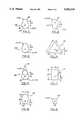
- FIG. 11is an enlarged view of the pearshaped feed through hole
- FIG. 12is an enlarged view of the tangent line feed through hole
- FIG. 13is an enlarged view of the snow cone feed through hole
- FIG. 14is an enlarged view of the ellipse feed through hole
- FIG. 15is an enlarged view of the reverse pear feed through hole
- FIG. 16is an enlarged view of the equilateral triangle feed through hole
- FIG. 17is an enlarged view of the rectangle feed through hole.
- FIG. 18is an enlarged view of a circular feed through hole.
- the principal elements of the present inventioninclude an upper microstrip radiating patch 22 separated by dielectric spacers from a lower microstrip radiating patch 26.
- a second set of dielectric spacersseparate the lower patch 26 from an upper ground plane 30 and a lower ground plane 32.
- a modal shorting pin 34interconnects and extends between each of the upper patch 22, lower patch 26, upper ground plane 30, and lower ground plane 32.
- a backward wave feed network 36feeds the patches 22, 26 through a pair of feed pins 38, 40 which extend through feed through holes 42 (the second hole not being shown in FIG. 1) in lower patch 26.
- One port 46provides the connection for signal transmission and another port 48 provides a termination point for a dummy load (not shown).
- the antenna 20can be constructed from eight boards with copper layering thereon, the copper layering being etched off during manufacture as desired to form the proper board.
- the top five boardsall have a nominal thickness of .0625 inches and can be made from R. T. Duroid with a relative dielectric constant of 2.33. Other values of dielectric constant may be used to vary pattern shape.
- the boardshave been numbered 1-8 starting with the upper board.
- Board No. 1has an upper copper patch of approximately 1.45 inch radius with a center hole 50 and two feed pin holes 52 located at a nominal .59 inch radius. Board No.
- Board No. 2has no copper layering and has a center hole 54 and two feed pin holes 56 located at a nominal .59 inch radius.
- Board No. 3has an upper circular patch of copper layering to form the lower patch 26 with a nominal 1.73 inch radius, a center hole 58 and two feed through holes 42 having any one of the shapes shown in FIGS. 11-18.
- Board No. 4has no copper layering, with a center hole 62 and two feed pin holes 64.
- Board No. 5has no copper layering with a center hole 66 and a pair of feed pin holes 68. Board No.
- Board No. 7has an upper Z-like shape copper trace 76 along its upper surface and an offset copper trace 78 along its lower surface to form the backward wave feed network 36. Each trace 76, 78 has a line width of approximately .025 inches, the traces, 76, 78 having an overlap length of 1.32 inches. Also, a center pin hole 80 extends through Board No. 7. Board No.
- FIG. 8includes a lower copper layer which forms the lower ground plane 32 with a pair of circular cutouts 82, 84 to accommodate the two connections 46, 48 for backward wave feed network 36 as best shown in FIG. 1. Additionally, a trio of cavity pins 86 are representationally shown on Board No. 8 in FIG. 10 surrounding each circular hole cutout 82, 84 and which extend between ground planes 30, 32 to help isolate these connections.
- FIGS. 11-18The various feed through hole shapes are best shown in FIGS. 11-18.
- a pear-shaped hole 100was tested which comprises a pair of overlapping circles, one circle 102 being .1 inch diameter, the other circle 104 being .15 inch diameter, the centers being spaced by .075 inches with the feed pin 38 oriented in this, and all other feed through holes, as shown.
- FIG. 12depicts a tangent line feed through hole 106 which is the same as the pear-shaped hole 102 except with an additional area cut out along tangent lines drawn on both sides between the two holes 102, 104.
- the next hole shapeis shown in FIG.
- the next shapeis the ellipse shape 112 shown in FIG. 14 and is generally comprised of an ellipse having a width of .15 inches and a length of .225 inches with the feed through pin 38 oriented .075 inches from the lower end of the ellipse.
- the next hole shapeis the reverse pear-shape 114 shown in FIG. 15 which is essentially the same as that shown in FIG. 11 as the pear-shaped hole 102 except flip-flopped to have the smaller end closest to the center of the patch 26.
- the next shaped holeis the equilateral triangle 116 shown in FIG. 16 measuring .3 inches per side with the feed pin 38 centered .075 inches outboard from the lower edge thereof.
- the next holeis the rectangularshaped hole 118 shown in FIG. 17 which is a rectangle having a shorter side of .15 inches and a longer side of .225 inches with the feed pin 38 spaced .075 inches outboard from the lower edge thereof.
- the last holeis the circular hole 120 shown in FIG. 18 and is generally comprised of a .1 inch diameter hole with a feed pin 38 extending through its center. This circular hole shape is the typical prior art feed through hole utilized in an antenna of this nature.
- the pear-shaped holegave the widest bandwidth at the upper frequency
- the tangent line shapegave the widest bandwidth at the lower frequency
- the tangent line shapegave the best overall combination of bandwidths for both frequencies in that the high frequency bandwidth for the tangent line shape ranked third.
- a characterization of the hole shapes by four qualitiesinclude the characteristic of whether the hole is elongated, tapered, rounded, or smooth.
- a holewas considered elongated if its length along the patch radius was longer than the circumferential length.
- the holewas considered tapered if its width narrowed more as the hole approached the patch outer edge compared to the opposite direction.
- the holewas considered rounded if the end toward the patch outer edge had a radius instead of converging to a sharp point.
- the holewas considered smooth if there were no sharp corners anywhere in the hole circumference.
- the antenna of the present inventionoperates as a circular microstrip patch radiator.
- a shorting or modal pin in the center of each patchforces the element into the TM 01 mode.
- This modal pinconnects the center of each radiating patch to the ground plane.
- the upper patchis resonant it uses the lower patch as a ground plane.
- the lower patchoperates against the upper ground plane and acts nearly independently of the upper element.
- the antennais fed through two feed pins which are oriented at right angles to each other to excite orthogonal modes and are 90° out of phase to achieve circular polarization.
- the bandwidth of the antennais increased by increasing the thickness of the dielectric material between the radiating patches.
- the input impedanceis controlled by placement of the feed pins along the radius of each circular patch. Feeding at a larger radius from the center of each patch causes a higher input impedance. As the upper patch has a smaller radius than the lower patch, and the feed pins are parallel to each other and perpendicular to each of the two patches, ordinarily different input impedances would be obtained for the patches. As the widest bandwidth match for both frequencies in a GPS system occurs when the input impedance circles 50 ohms within an acceptable VSWR at each resonance, and a 50 ohm input impedance corresponds to approximately one-third of the patch radius, it is desired to locate the feed pins near one-third of the radius.
- the backward wave coupler networkwhich forms the feed connection between the feed pins and signal connection greatly extends the frequency bandwidth defined by allowable input in VSWR.
- the backward wave couplerprovides an equal power split and a 90° phase shift between the output ports. These signals, when fed to the patches by pins separated by 90° , cause the antenna to radiate circular polarization.
- the backward wave coupleralso routes reflected signals due to impedance mismatch into an isolated port where a dummy load such as a resistor can dissipate the reflected power to minimize interference with the radiated signal. For the backward wave coupler to dissipate all reflected power, its two output ports must drive identical impedances.
Landscapes
- Physics & Mathematics (AREA)
- Electromagnetism (AREA)
- Waveguide Aerials (AREA)
Abstract
Description
This application is a continuation-in-part of Ser. No. 06/934,478 filed Nov. 24, 1986 now U.S. Pat. No. 4,827,271.
Circular patch microstrip antennas are well known in the art and have many advantages which make them particularly adapted for certain applications. In particular, a stacked microstrip patch antenna is relatively inexpensive and easily manufactured, rugged, readily conformed to surface mount to an irregular shape, has a broad reception pattern, and can be adapted to receive multiple frequencies through proper configuration of the patches.
One particular application includes utilizing a stacked microstrip patch antenna on an air frame for receiving signals transmitted by the Global Positioning System (GPS) satellites. In this application, the antenna must operate at dual frequencies and be physically small enough to be utilized in an array. Furthermore, the antenna should provide approximately hemispherical coverage and have its pattern roll-off sharply between 80° and 90° from broadside to reject signals from emitters on the horizon. Because of its conformability, the antenna is uniquely adapted for mounting to the host vehicle which could be double curved, and its characteristics provide a minimum impact on radar signature. The antenna must provide at least a 1.6% frequency bandwidth and circular polarization at both GPS frequencies. The antenna is ideal for use in a multi-element array for adaptive processing; a method of automatically steering nulls toward interfering signals. For this application, the antenna must provide at least 5% frequency bandwidth for good performance.
Some of the stacked microstrip antennas which are available in the prior art include the antenna disclosed in U.S. Pat. No. 4,070,676 which has square shaped microstrip patches stacked for dual frequency. However, based on the inventors' experience, this antenna does not exhibit the necessary frequency bandwidth for utilization as a GPS adaptive antenna. Still another microstrip patch antenna is disclosed at p. 255 of the 1984 IEEE Antennas and Propagation Digest which utilizes a triple frequency stacked microstrip element. However, once again the antenna bandwidth is not large enough to enable its use in a GPS adaptive antenna application. Still another stacked microstrip patch antenna is disclosed at p. 260 of the 1978 IEEE Antennas and Propagation Digest and this antenna has a pair of circular disks stacked one atop the other with a single feed extending through a hole in the lower disk and physically connected to the upper disk. However, as with the other antennas, this antenna does not exhibit the necessary frequency bandwidth to be utilized in a GPS adaptive antenna application.
The inventors herein have succeeded in developing an improved feed incorporating feed pins which are coupled to one of the patches for a dual frequency stacked circular microstrip patch antenna which increases the bandwidth including a wider frequency operating range within a prescribed VSWR, and a wider operating range for a prescribed antenna gain which permits its use with a GPS system, and especially with an adaptive nulling processor for interference rejection. The wider bandwidth permits the processor to develop deep nulls over a wide frequency range as is necessary for this system. The improved, wider bandwidth also minimizes the deleterious effects caused by manufacturing tolerances and environmental conditions which would otherwise shift a narrower band antenna out of the desired frequency range.
The dual frequency microstrip patch antenna includes two circular microstrip patches stacked concentrically, one over the other, with each patch resonating at a different frequency. In this improved design, only the upper patch has a direct connection with the feed network by way of two vertical feed through pins while the lower patch receives its excitation by capacitive coupling. The inventors herein have discovered that the feed through hole size and shape directly affect the frequency bandwidth of each patch while operating at their separate frequencies typical for a GPS antenna. With many of these holes, considerable bandwidth improvements were realized over using a standard, prior art, round feed through holes. In analyzing the results, four separable characteristics of the holes were identified for purposes of interpreting the resulting increased bandwidths. A hole was considered "elongated" if its length along the patch radius was longer than the circumferential length. A hole was considered "tapered" if its width narrowed more as the hole approached the patch outer edge compared to the opposite direction. The hole was considered "rounded" if the end toward the patch outer edge had a radius instead of converging to a sharp point. Lastly, the hole shape was considered "smooth" if there were no sharp corners anywhere over the hole circumference. In the final analysis, it was apparent that all four characteristics were important for an increased bandwidth. As explained in greater detail below, elongated, rounded, and smooth characteristics were common to the two shapes giving the best lower frequency bandwidth. On the other hand, elongated and tapered characteristics were common to the three hole shapes giving the widest upper frequency bandwidth. The one hole shape which included all four characteristics appeared to be the best compromise in that it provided the largest bandwidth at the lower frequency and the third largest bandwidth at the upper frequency.
The antenna of the present invention is comprised of eight boards, some of which have a copper layering on one or both sides thereof, and others of which have no copper and are used as spacers. Furthermore, the boards themselves may be of varying thicknesses although in the preferred embodiment the top five boards are substantially the same thickness and the bottom three boards are smaller than the top five boards. From top to bottom, the eight boards can be generally described as follows:
Board No. 1 has an upper layer of copper configured in a circle to form the upper patch.
Board No. 2 is a layer of dielectric with no copper on either side.
Board No. 3 has an upper layer of copper to form the lower patch and has a pair of feed through holes which can be shaped in accordance with one of the several embodiments disclosed herein to accommodate insertion of feed pins.
Board No. 4 is a layer of dielectric with no copper on either side.
Board No. 5 is a layer of dielectric with no copper on either side.
Board No. 6 is a dielectric with a layer of copper along its upper surface with a pair of circles cut out on its upper side for the feed pins to pass through.
Board No. 7 is a dielectric of greatly reduced thickness having a copper trace on the upper and lower sides forming the backward wave coupler.
Board No. 8 is a dielectric of reduced thickness with copper layering on the bottom except for two circular patches to accommodate termination and feed connections for the backward wave coupler.
In addition to the modal pin which interconnects both the upper and lower patches to the two ground planes, a number of cavity pins extend between the ground planes surrounding the two feed connections. Also, two pins connect the upper patch to the backward wave coupler.
By bonding these boards together, a rigid structure is formed which can be conformed to fit the surface on which the antenna is to be mounted and yet provide a low profile. Furthermore, with the feed through hole design of the present invention, an increased bandwidth is achieved which enables the antenna to be used in a GPS system.
While the principal advantages and features of the present invention have been briefly described, a more complete understanding of the invention may be obtained by referring to the drawings and the Detailed Description of the Preferred Embodiment which follows.
FIG. 1 is a perspective of the antenna partially broken away to detail the various layers of the antenna;
FIG. 2 is a cross-sectional view of the antenna which gives further detail on the various layers used to form the antenna;
FIG. 3 is a top view of board 1 as shown in FIG. 2;
FIG. 4 is a top view ofboard 2 as shown in FIG. 2;
FIG. 5 is a top view ofboard 3 as shown in FIG. 2;
FIG. 6 is a top view ofboard 4 as shown in FIG. 2;
FIG. 7 is a top view ofboard 5 as shown in FIG. 2;
FIG. 8 is a top view ofboard 6 as shown in FIG. 2;
FIG. 9 is a top view of board 7 as shown in FIG. 2;
FIG. 10 is a top view ofboard 8 as shown in FIG. 2;
FIG. 11 is an enlarged view of the pearshaped feed through hole;
FIG. 12 is an enlarged view of the tangent line feed through hole;
FIG. 13 is an enlarged view of the snow cone feed through hole;
FIG. 14 is an enlarged view of the ellipse feed through hole;
FIG. 15 is an enlarged view of the reverse pear feed through hole;
FIG. 16 is an enlarged view of the equilateral triangle feed through hole;
FIG. 17 is an enlarged view of the rectangle feed through hole; and
FIG. 18 is an enlarged view of a circular feed through hole.
As shown in FIG. 1, the principal elements of the present invention include an uppermicrostrip radiating patch 22 separated by dielectric spacers from a lowermicrostrip radiating patch 26. A second set of dielectric spacers separate thelower patch 26 from anupper ground plane 30 and alower ground plane 32. Amodal shorting pin 34 interconnects and extends between each of theupper patch 22,lower patch 26,upper ground plane 30, andlower ground plane 32. A backwardwave feed network 36 feeds thepatches lower patch 26. Oneport 46 provides the connection for signal transmission and anotherport 48 provides a termination point for a dummy load (not shown).
As shown in greater detail in FIGS. 2 and 3, theantenna 20 can be constructed from eight boards with copper layering thereon, the copper layering being etched off during manufacture as desired to form the proper board. In the preferred embodiment, the top five boards all have a nominal thickness of .0625 inches and can be made from R. T. Duroid with a relative dielectric constant of 2.33. Other values of dielectric constant may be used to vary pattern shape. For convenience, the boards have been numbered 1-8 starting with the upper board. As shown in FIGS. 2 and 3, Board No. 1 has an upper copper patch of approximately 1.45 inch radius with acenter hole 50 and two feed pin holes 52 located at a nominal .59 inch radius. Board No. 2 has no copper layering and has a center hole 54 and two feed pin holes 56 located at a nominal .59 inch radius. Board No. 3 has an upper circular patch of copper layering to form thelower patch 26 with a nominal 1.73 inch radius, acenter hole 58 and two feed throughholes 42 having any one of the shapes shown in FIGS. 11-18. Board No. 4 has no copper layering, with acenter hole 62 and two feed pin holes 64. Board No. 5 has no copper layering with acenter hole 66 and a pair of feed pin holes 68. Board No. 6 has an upper side with copper layering covering almost the entire upper surface to form theupper ground plane 30, with a center hole 70 and a pair ofcircular holes 72 cut from the copper layering to avoid contact with feed pins 38, 40, and a pair of feed pin holes 74. Board No. 7 has an upper Z-likeshape copper trace 76 along its upper surface and an offsetcopper trace 78 along its lower surface to form the backwardwave feed network 36. Eachtrace center pin hole 80 extends through Board No. 7. Board No. 8 includes a lower copper layer which forms thelower ground plane 32 with a pair ofcircular cutouts connections wave feed network 36 as best shown in FIG. 1. Additionally, a trio of cavity pins 86 are representationally shown on Board No. 8 in FIG. 10 surrounding eachcircular hole cutout
The various feed through hole shapes are best shown in FIGS. 11-18. As shown in FIG. 11, a pear-shapedhole 100 was tested which comprises a pair of overlapping circles, onecircle 102 being .1 inch diameter, the other circle 104 being .15 inch diameter, the centers being spaced by .075 inches with thefeed pin 38 oriented in this, and all other feed through holes, as shown. FIG. 12 depicts a tangent line feed throughhole 106 which is the same as the pear-shapedhole 102 except with an additional area cut out along tangent lines drawn on both sides between the twoholes 102, 104. The next hole shape is shown in FIG. 13 as thesnow cone shape 108 and is essentially the same as thetangent line hole 106 except the tangent lines along each side of the holes extended to apoint 110. The next shape is theellipse shape 112 shown in FIG. 14 and is generally comprised of an ellipse having a width of .15 inches and a length of .225 inches with the feed throughpin 38 oriented .075 inches from the lower end of the ellipse. The next hole shape is the reverse pear-shape 114 shown in FIG. 15 which is essentially the same as that shown in FIG. 11 as the pear-shapedhole 102 except flip-flopped to have the smaller end closest to the center of thepatch 26. The next shaped hole is theequilateral triangle 116 shown in FIG. 16 measuring .3 inches per side with thefeed pin 38 centered .075 inches outboard from the lower edge thereof. The next hole is therectangularshaped hole 118 shown in FIG. 17 which is a rectangle having a shorter side of .15 inches and a longer side of .225 inches with thefeed pin 38 spaced .075 inches outboard from the lower edge thereof. The last hole is thecircular hole 120 shown in FIG. 18 and is generally comprised of a .1 inch diameter hole with afeed pin 38 extending through its center. This circular hole shape is the typical prior art feed through hole utilized in an antenna of this nature.
These various hole shapes were individually tested, each hole being oriented so that the centroid of the hole area was between the feed through pin and the outer edge of the microstrip patch, except for the reverse pear hole of FIG. 15. For example, the point of the snow cone hole pointed away from the center of the microstrip patch. The bandwidths of VSWR less than 1.7:1 that were measured for each hole shape are summarized in the following table for the low (BL) and the high (BH) GPS frequencies. Because the antenna was fed through a backward wave coupler to produce circular polarization, there were two connector ports available to measure. Input A caused left-hand circular polarization to be radiated and input B caused right-hand circular polarization to be radiated. Measurements were taken at both ports and averaged to reduce the influence of the feed network. Relative rankings of the bandwidths at the lower and upper frequencies for each hole shape are indicated in the following table.
TABLE ______________________________________ MEASUREMENT RESULTS Bandwith Hole Shape Description MHz Elon- Hole Shape BL BH gated Tapered Rounded Smooth ______________________________________ Pear 18 55 X X X Shaped Tangent 28 49 X X X X Line Snow Cone 18 ○54 X X Ellipse ○24 48 X X X Reverse 16 46 X Pear Equilateral 17 47 X X Triangle Rectangle 19 41 X Circular 14 46 X X ______________________________________ Largest Bandwidth ○ 2nd Largest 3rd Largest
The pear-shaped hole gave the widest bandwidth at the upper frequency, the tangent line shape gave the widest bandwidth at the lower frequency, and the tangent line shape gave the best overall combination of bandwidths for both frequencies in that the high frequency bandwidth for the tangent line shape ranked third.
Also shown in the table is a characterization of the hole shapes by four qualities. These include the characteristic of whether the hole is elongated, tapered, rounded, or smooth. A hole was considered elongated if its length along the patch radius was longer than the circumferential length. The hole was considered tapered if its width narrowed more as the hole approached the patch outer edge compared to the opposite direction. The hole was considered rounded if the end toward the patch outer edge had a radius instead of converging to a sharp point. The hole was considered smooth if there were no sharp corners anywhere in the hole circumference.
As can be seen from the measurements, all four characteristics are important in achieving a wide bandwidth. Elongated, rounded, and smooth characteristics are common to the two shapes giving the best lower frequency bandwidth while elongated and tapered shapes were common to the three hole shapes giving the widest upper frequency bandwidth.
The antenna of the present invention operates as a circular microstrip patch radiator. A shorting or modal pin in the center of each patch forces the element into the TM01 mode. This modal pin connects the center of each radiating patch to the ground plane. When the upper patch is resonant it uses the lower patch as a ground plane. The lower patch operates against the upper ground plane and acts nearly independently of the upper element. The antenna is fed through two feed pins which are oriented at right angles to each other to excite orthogonal modes and are 90° out of phase to achieve circular polarization. The bandwidth of the antenna is increased by increasing the thickness of the dielectric material between the radiating patches.
The input impedance is controlled by placement of the feed pins along the radius of each circular patch. Feeding at a larger radius from the center of each patch causes a higher input impedance. As the upper patch has a smaller radius than the lower patch, and the feed pins are parallel to each other and perpendicular to each of the two patches, ordinarily different input impedances would be obtained for the patches. As the widest bandwidth match for both frequencies in a GPS system occurs when theinput impedance circles 50 ohms within an acceptable VSWR at each resonance, and a 50 ohm input impedance corresponds to approximately one-third of the patch radius, it is desired to locate the feed pins near one-third of the radius. This is achieved by physically connecting the upper ends of the feed pins at the one-third radius point to the upper patch, and by utilizing modified feed through holes in accordance with one of the shapes shown in FIG. 11-18 and capacitively coupling the feed pins to the lower patch to simulate connection of the feed pins further from the center than actual. There is also capacitive coupling between the upper and lower patch that excites the lower patch. By utilizing these modified feed pin holes, an increase in bandwidth at each resonance may be achieved as detailed in the table.
The backward wave coupler network which forms the feed connection between the feed pins and signal connection greatly extends the frequency bandwidth defined by allowable input in VSWR. The backward wave coupler provides an equal power split and a 90° phase shift between the output ports. These signals, when fed to the patches by pins separated by 90° , cause the antenna to radiate circular polarization. Furthermore, the backward wave coupler also routes reflected signals due to impedance mismatch into an isolated port where a dummy load such as a resistor can dissipate the reflected power to minimize interference with the radiated signal. For the backward wave coupler to dissipate all reflected power, its two output ports must drive identical impedances. This condition exists because the two feed points on the patch are orthogonal and isolated from each other, forming equal and independent impedances. The backward wave coupler when combined with the dual feed pin feed for circular polarization results in an input VSWR of 1.5:1 or less over a nearly octave bandwidth of 1.2:2 GHz. A VSWR of 1.7:1 or lower is usually very acceptable.
There are various changes and modifications which may be made to the invention as would be apparent to those skilled in the art. However, these changes or modifications are included in the teaching of the disclosure, and it is intended that the invention be limited only by the scope of the claims appended hereto.
Claims (5)
1. In a multiple frequency stacked microstrip patch antenna, said antenna including at least two spaced apart radiating patches which are shaped to resonate at one of the GPS frequencies, and a ground plane, one of said patches being stacked substantially vertically above the other and the ground plane, said patches being sized and spaced to resonate at different frequencies, a feed means comprising a pair of feed pins extending through holes in the lower patch at a point approximately 0.075 inches along their respective longitudinal axes from the inner most edge of said holes for capacitive coupling thereto and terminating in a physical electrical connection to the upper patch, the longitudinal axes of the holes being substantially radially aligned with the center of the lower patch, the improvement comprising means to match the input impedances to each of the patches at their respective bandwidths comprising a modified shape for said feed-through holes, each of the holes having an arcuate portion substantially defined by a circle having a radius of approximately 0.075 inches, said feed pins extending through said holes at substantially the center of the circles, and each of said holes having a second arcuate portion substantially defined by a circle having a radius of approximately 0.05 inches, said first and second circles at least partially overlapping.
2. The antenna of claim 1 further comprising a pair of tangent lines interconnecting said first and second circles and forming apart of the circumference of said holes, said holes being each solely comprising of the first and second arcuate portions and the pair of tangent lines.
3. In a multiple frequency stacked microstrip patch antenna, said antenna including at least two spaced apart radiating patches and a ground plane, one of said patches being stacked substantially vertically above the other and the ground plane, said patches being sized and spaced to resonate at different frequencies, a feed means comprising a pair of feed pins extending though holes in the lower patch for capacitive coupling thereto and terminating in a physical electrical connection to the upper patch, the improvement comprising means to match the input impedances to each of the patches at their respective operating frequencies to thereby improve their respective bandwidths comprising a modified shape for said feed-through holes, each of the holes having a first and second arcuate portion substantially defined by a circle where the second circle radius is smaller than the radius of said first circle and the first and second circles are at least partially overlapping, said feed pins extending through said holes at substantially the center of the circles and the longitudinal axes of the holes are substantially radially aligned with the center of the lower patch.
4. The antenna of claim 3 further comprising a pair of tangent lines interconnecting said first and second circles and forming apart of the circumference of said holes, said holes being each solely comprised of the first and second arcuate portions and the pair of tangent lines.
5. The antenna of claim 4 wherein the holes are positioned with the arcuate portion with the largest radius being closest to th center of their associated patch.
Priority Applications (1)
| Application Number | Priority Date | Filing Date | Title |
|---|---|---|---|
| US07/261,262US5003318A (en) | 1986-11-24 | 1988-10-24 | Dual frequency microstrip patch antenna with capacitively coupled feed pins |
Applications Claiming Priority (2)
| Application Number | Priority Date | Filing Date | Title |
|---|---|---|---|
| US06/934,478US4827271A (en) | 1986-11-24 | 1986-11-24 | Dual frequency microstrip patch antenna with improved feed and increased bandwidth |
| US07/261,262US5003318A (en) | 1986-11-24 | 1988-10-24 | Dual frequency microstrip patch antenna with capacitively coupled feed pins |
Related Parent Applications (1)
| Application Number | Title | Priority Date | Filing Date |
|---|---|---|---|
| US06/934,478Continuation-In-PartUS4827271A (en) | 1986-11-24 | 1986-11-24 | Dual frequency microstrip patch antenna with improved feed and increased bandwidth |
Publications (1)
| Publication Number | Publication Date |
|---|---|
| US5003318Atrue US5003318A (en) | 1991-03-26 |
Family
ID=26948492
Family Applications (1)
| Application Number | Title | Priority Date | Filing Date |
|---|---|---|---|
| US07/261,262Expired - LifetimeUS5003318A (en) | 1986-11-24 | 1988-10-24 | Dual frequency microstrip patch antenna with capacitively coupled feed pins |
Country Status (1)
| Country | Link |
|---|---|
| US (1) | US5003318A (en) |
Cited By (195)
| Publication number | Priority date | Publication date | Assignee | Title |
|---|---|---|---|---|
| USH1460H (en)* | 1992-04-02 | 1995-07-04 | The United States Of America As Represented By The Secretary Of The Air Force | Spiral-mode or sinuous microscrip antenna with variable ground plane spacing |
| US5652595A (en)* | 1995-05-04 | 1997-07-29 | Motorola, Inc. | Patch antenna including reactive loading |
| FR2785451A1 (en)* | 1998-11-04 | 2000-05-05 | Thomson Csf | MULTIFUNCTIONAL PRINTED ANTENNA |
| US6069589A (en)* | 1999-07-08 | 2000-05-30 | Scientific-Atlanta, Inc. | Low profile dual frequency magnetic radiator for little low earth orbit satellite communication system |
| US6114998A (en)* | 1997-10-01 | 2000-09-05 | Telefonaktiebolaget Lm Ericsson (Publ) | Antenna unit having electrically steerable transmit and receive beams |
| US6121931A (en)* | 1996-07-04 | 2000-09-19 | Skygate International Technology Nv | Planar dual-frequency array antenna |
| US6166692A (en)* | 1999-03-29 | 2000-12-26 | The United States Of America As Represented By The Secretary Of The Army | Planar single feed circularly polarized microstrip antenna with enhanced bandwidth |
| US6211823B1 (en)* | 1998-04-27 | 2001-04-03 | Atx Research, Inc. | Left-hand circular polarized antenna for use with GPS systems |
| US6222503B1 (en)* | 1997-01-10 | 2001-04-24 | William Gietema | System and method of integrating and concealing antennas, antenna subsystems and communications subsystems |
| US6239750B1 (en)* | 1998-08-28 | 2001-05-29 | Telefonaltiebolaget Lm Ericsson (Publ) | Antenna arrangement |
| US6252553B1 (en) | 2000-01-05 | 2001-06-26 | The Mitre Corporation | Multi-mode patch antenna system and method of forming and steering a spatial null |
| EP1069646A3 (en)* | 1999-07-10 | 2001-07-04 | ALAN DICK & COMPANY LIMITED | Patch antenna |
| US6369761B1 (en)* | 2000-04-17 | 2002-04-09 | Receptec L.L.C. | Dual-band antenna |
| US6470174B1 (en) | 1997-10-01 | 2002-10-22 | Telefonaktiebolaget Lm Ericsson (Publ) | Radio unit casing including a high-gain antenna |
| EP1162687A3 (en)* | 2000-06-09 | 2003-05-14 | Sony Corporation | Antenna element, adaptive antenna apparatus, and radio communication apparatus |
| US6597316B2 (en) | 2001-09-17 | 2003-07-22 | The Mitre Corporation | Spatial null steering microstrip antenna array |
| US20030214443A1 (en)* | 2002-03-15 | 2003-11-20 | Bauregger Frank N. | Dual-element microstrip patch antenna for mitigating radio frequency interference |
| WO2004019450A1 (en)* | 2002-08-22 | 2004-03-04 | Skycross, Inc. | Apparatus and method for forming a monolithic surface-mountable antenna |
| US20040117118A1 (en)* | 2002-12-12 | 2004-06-17 | Collins Anthony L. | System and method for determining downhole clock drift |
| US20040212536A1 (en)* | 2003-02-05 | 2004-10-28 | Fujitsu Limited | Antenna, method and construction of mounting thereof, and electronic device having antenna |
| US20050093746A1 (en)* | 2001-08-31 | 2005-05-05 | Paul Diament | Systems and methods for providing optimized patch antenna excitation for mutually coupled patches |
| US6930260B2 (en) | 2001-02-28 | 2005-08-16 | Vip Investments Ltd. | Switch matrix |
| US20060055603A1 (en)* | 2004-09-10 | 2006-03-16 | Joseph Jesson | Concealed planar antenna |
| US20060273969A1 (en)* | 2004-07-20 | 2006-12-07 | Mehran Aminzadeh | Antenna module |
| US20070085741A1 (en)* | 2005-10-17 | 2007-04-19 | Rafi Gholamreza Z | Multi-band antenna |
| US20070183449A1 (en)* | 2005-09-07 | 2007-08-09 | Vantage Controls, Inc. | Radio frequency multiple protocol bridge |
| US7307542B1 (en) | 2003-09-03 | 2007-12-11 | Vantage Controls, Inc. | System and method for commissioning addressable lighting systems |
| US7394451B1 (en) | 2003-09-03 | 2008-07-01 | Vantage Controls, Inc. | Backlit display with motion sensor |
| US20080309578A1 (en)* | 2006-02-01 | 2008-12-18 | Electronics And Telecommunications Research Institute | Antenna Using Proximity-Coupling Between Radiation Patch and Short-Ended Feed Line, Rfid Tag Employing the Same, and Antenna Impedance Matching Method Thereof |
| US20080309572A1 (en)* | 2007-06-14 | 2008-12-18 | Harris Corporation | Broadband planar dipole antenna structure and associated methods |
| US20080316112A1 (en)* | 2006-01-17 | 2008-12-25 | Yue Ping Zhang | Antennas |
| US20090289852A1 (en)* | 2008-05-23 | 2009-11-26 | Agc Automotive Americas R&D, Inc. | Multi-layer offset patch antenna |
| US7755506B1 (en) | 2003-09-03 | 2010-07-13 | Legrand Home Systems, Inc. | Automation and theater control system |
| US20140125541A1 (en)* | 2012-11-08 | 2014-05-08 | Samsung Electronics Co., Ltd. | End fire antenna apparatus and electronic apparatus having the same |
| CN104051856A (en)* | 2013-03-15 | 2014-09-17 | 香港城市大学 | patch antenna |
| US20140266918A1 (en)* | 2013-03-14 | 2014-09-18 | Hemisphere Gnss Inc. | Low profile, wideband gnss dual frequency antenna structure |
| US20150236424A1 (en)* | 2012-04-05 | 2015-08-20 | Tallysman Wireless Inc. | Capacitively coupled patch antenna |
| US9608740B2 (en) | 2015-07-15 | 2017-03-28 | At&T Intellectual Property I, L.P. | Method and apparatus for launching a wave mode that mitigates interference |
| US9615269B2 (en) | 2014-10-02 | 2017-04-04 | At&T Intellectual Property I, L.P. | Method and apparatus that provides fault tolerance in a communication network |
| US9628116B2 (en) | 2015-07-14 | 2017-04-18 | At&T Intellectual Property I, L.P. | Apparatus and methods for transmitting wireless signals |
| US9640850B2 (en) | 2015-06-25 | 2017-05-02 | At&T Intellectual Property I, L.P. | Methods and apparatus for inducing a non-fundamental wave mode on a transmission medium |
| US9667317B2 (en) | 2015-06-15 | 2017-05-30 | At&T Intellectual Property I, L.P. | Method and apparatus for providing security using network traffic adjustments |
| US9674711B2 (en) | 2013-11-06 | 2017-06-06 | At&T Intellectual Property I, L.P. | Surface-wave communications and methods thereof |
| US9685992B2 (en) | 2014-10-03 | 2017-06-20 | At&T Intellectual Property I, L.P. | Circuit panel network and methods thereof |
| US9692101B2 (en) | 2014-08-26 | 2017-06-27 | At&T Intellectual Property I, L.P. | Guided wave couplers for coupling electromagnetic waves between a waveguide surface and a surface of a wire |
| US9699785B2 (en) | 2012-12-05 | 2017-07-04 | At&T Intellectual Property I, L.P. | Backhaul link for distributed antenna system |
| US9705610B2 (en) | 2014-10-21 | 2017-07-11 | At&T Intellectual Property I, L.P. | Transmission device with impairment compensation and methods for use therewith |
| US9705561B2 (en) | 2015-04-24 | 2017-07-11 | At&T Intellectual Property I, L.P. | Directional coupling device and methods for use therewith |
| US9722318B2 (en) | 2015-07-14 | 2017-08-01 | At&T Intellectual Property I, L.P. | Method and apparatus for coupling an antenna to a device |
| US9729197B2 (en) | 2015-10-01 | 2017-08-08 | At&T Intellectual Property I, L.P. | Method and apparatus for communicating network management traffic over a network |
| US9735833B2 (en) | 2015-07-31 | 2017-08-15 | At&T Intellectual Property I, L.P. | Method and apparatus for communications management in a neighborhood network |
| US9742462B2 (en) | 2014-12-04 | 2017-08-22 | At&T Intellectual Property I, L.P. | Transmission medium and communication interfaces and methods for use therewith |
| US9742521B2 (en) | 2014-11-20 | 2017-08-22 | At&T Intellectual Property I, L.P. | Transmission device with mode division multiplexing and methods for use therewith |
| US9749013B2 (en) | 2015-03-17 | 2017-08-29 | At&T Intellectual Property I, L.P. | Method and apparatus for reducing attenuation of electromagnetic waves guided by a transmission medium |
| US9749053B2 (en) | 2015-07-23 | 2017-08-29 | At&T Intellectual Property I, L.P. | Node device, repeater and methods for use therewith |
| US9748626B2 (en) | 2015-05-14 | 2017-08-29 | At&T Intellectual Property I, L.P. | Plurality of cables having different cross-sectional shapes which are bundled together to form a transmission medium |
| US9762289B2 (en) | 2014-10-14 | 2017-09-12 | At&T Intellectual Property I, L.P. | Method and apparatus for transmitting or receiving signals in a transportation system |
| US9769128B2 (en) | 2015-09-28 | 2017-09-19 | At&T Intellectual Property I, L.P. | Method and apparatus for encryption of communications over a network |
| US9768833B2 (en) | 2014-09-15 | 2017-09-19 | At&T Intellectual Property I, L.P. | Method and apparatus for sensing a condition in a transmission medium of electromagnetic waves |
| US9769020B2 (en) | 2014-10-21 | 2017-09-19 | At&T Intellectual Property I, L.P. | Method and apparatus for responding to events affecting communications in a communication network |
| US9780834B2 (en) | 2014-10-21 | 2017-10-03 | At&T Intellectual Property I, L.P. | Method and apparatus for transmitting electromagnetic waves |
| US9787412B2 (en) | 2015-06-25 | 2017-10-10 | At&T Intellectual Property I, L.P. | Methods and apparatus for inducing a fundamental wave mode on a transmission medium |
| US9793954B2 (en) | 2015-04-28 | 2017-10-17 | At&T Intellectual Property I, L.P. | Magnetic coupling device and methods for use therewith |
| US9793955B2 (en) | 2015-04-24 | 2017-10-17 | At&T Intellectual Property I, Lp | Passive electrical coupling device and methods for use therewith |
| US9793951B2 (en) | 2015-07-15 | 2017-10-17 | At&T Intellectual Property I, L.P. | Method and apparatus for launching a wave mode that mitigates interference |
| US9800327B2 (en) | 2014-11-20 | 2017-10-24 | At&T Intellectual Property I, L.P. | Apparatus for controlling operations of a communication device and methods thereof |
| US9820146B2 (en) | 2015-06-12 | 2017-11-14 | At&T Intellectual Property I, L.P. | Method and apparatus for authentication and identity management of communicating devices |
| US9838896B1 (en) | 2016-12-09 | 2017-12-05 | At&T Intellectual Property I, L.P. | Method and apparatus for assessing network coverage |
| US9838078B2 (en) | 2015-07-31 | 2017-12-05 | At&T Intellectual Property I, L.P. | Method and apparatus for exchanging communication signals |
| US9847850B2 (en) | 2014-10-14 | 2017-12-19 | At&T Intellectual Property I, L.P. | Method and apparatus for adjusting a mode of communication in a communication network |
| US9847566B2 (en) | 2015-07-14 | 2017-12-19 | At&T Intellectual Property I, L.P. | Method and apparatus for adjusting a field of a signal to mitigate interference |
| US9853342B2 (en) | 2015-07-14 | 2017-12-26 | At&T Intellectual Property I, L.P. | Dielectric transmission medium connector and methods for use therewith |
| KR101803208B1 (en) | 2016-10-19 | 2017-12-28 | 홍익대학교 산학협력단 | Beamfoaming anttena using single radiator multi port |
| US9860075B1 (en) | 2016-08-26 | 2018-01-02 | At&T Intellectual Property I, L.P. | Method and communication node for broadband distribution |
| US9865911B2 (en) | 2015-06-25 | 2018-01-09 | At&T Intellectual Property I, L.P. | Waveguide system for slot radiating first electromagnetic waves that are combined into a non-fundamental wave mode second electromagnetic wave on a transmission medium |
| US9866276B2 (en) | 2014-10-10 | 2018-01-09 | At&T Intellectual Property I, L.P. | Method and apparatus for arranging communication sessions in a communication system |
| US9866309B2 (en) | 2015-06-03 | 2018-01-09 | At&T Intellectual Property I, Lp | Host node device and methods for use therewith |
| US9871282B2 (en) | 2015-05-14 | 2018-01-16 | At&T Intellectual Property I, L.P. | At least one transmission medium having a dielectric surface that is covered at least in part by a second dielectric |
| US9871558B2 (en) | 2014-10-21 | 2018-01-16 | At&T Intellectual Property I, L.P. | Guided-wave transmission device and methods for use therewith |
| US9871283B2 (en) | 2015-07-23 | 2018-01-16 | At&T Intellectual Property I, Lp | Transmission medium having a dielectric core comprised of plural members connected by a ball and socket configuration |
| US9876264B2 (en) | 2015-10-02 | 2018-01-23 | At&T Intellectual Property I, Lp | Communication system, guided wave switch and methods for use therewith |
| US9876570B2 (en) | 2015-02-20 | 2018-01-23 | At&T Intellectual Property I, Lp | Guided-wave transmission device with non-fundamental mode propagation and methods for use therewith |
| US9876605B1 (en) | 2016-10-21 | 2018-01-23 | At&T Intellectual Property I, L.P. | Launcher and coupling system to support desired guided wave mode |
| US9882257B2 (en) | 2015-07-14 | 2018-01-30 | At&T Intellectual Property I, L.P. | Method and apparatus for launching a wave mode that mitigates interference |
| US9887447B2 (en) | 2015-05-14 | 2018-02-06 | At&T Intellectual Property I, L.P. | Transmission medium having multiple cores and methods for use therewith |
| US9893795B1 (en) | 2016-12-07 | 2018-02-13 | At&T Intellectual Property I, Lp | Method and repeater for broadband distribution |
| US9904535B2 (en) | 2015-09-14 | 2018-02-27 | At&T Intellectual Property I, L.P. | Method and apparatus for distributing software |
| US9906269B2 (en) | 2014-09-17 | 2018-02-27 | At&T Intellectual Property I, L.P. | Monitoring and mitigating conditions in a communication network |
| US9912381B2 (en) | 2015-06-03 | 2018-03-06 | At&T Intellectual Property I, Lp | Network termination and methods for use therewith |
| US9911020B1 (en) | 2016-12-08 | 2018-03-06 | At&T Intellectual Property I, L.P. | Method and apparatus for tracking via a radio frequency identification device |
| US9912027B2 (en) | 2015-07-23 | 2018-03-06 | At&T Intellectual Property I, L.P. | Method and apparatus for exchanging communication signals |
| US9913139B2 (en) | 2015-06-09 | 2018-03-06 | At&T Intellectual Property I, L.P. | Signal fingerprinting for authentication of communicating devices |
| US9912419B1 (en) | 2016-08-24 | 2018-03-06 | At&T Intellectual Property I, L.P. | Method and apparatus for managing a fault in a distributed antenna system |
| US9912033B2 (en) | 2014-10-21 | 2018-03-06 | At&T Intellectual Property I, Lp | Guided wave coupler, coupling module and methods for use therewith |
| US9917341B2 (en) | 2015-05-27 | 2018-03-13 | At&T Intellectual Property I, L.P. | Apparatus and method for launching electromagnetic waves and for modifying radial dimensions of the propagating electromagnetic waves |
| US9930668B2 (en) | 2013-05-31 | 2018-03-27 | At&T Intellectual Property I, L.P. | Remote distributed antenna system |
| US9927517B1 (en) | 2016-12-06 | 2018-03-27 | At&T Intellectual Property I, L.P. | Apparatus and methods for sensing rainfall |
| US9948354B2 (en) | 2015-04-28 | 2018-04-17 | At&T Intellectual Property I, L.P. | Magnetic coupling device with reflective plate and methods for use therewith |
| US9948355B2 (en) | 2014-10-21 | 2018-04-17 | At&T Intellectual Property I, L.P. | Apparatus for providing communication services and methods thereof |
| US9948333B2 (en) | 2015-07-23 | 2018-04-17 | At&T Intellectual Property I, L.P. | Method and apparatus for wireless communications to mitigate interference |
| US9954287B2 (en) | 2014-11-20 | 2018-04-24 | At&T Intellectual Property I, L.P. | Apparatus for converting wireless signals and electromagnetic waves and methods thereof |
| US9954286B2 (en) | 2014-10-21 | 2018-04-24 | At&T Intellectual Property I, L.P. | Guided-wave transmission device with non-fundamental mode propagation and methods for use therewith |
| US9967173B2 (en) | 2015-07-31 | 2018-05-08 | At&T Intellectual Property I, L.P. | Method and apparatus for authentication and identity management of communicating devices |
| US9973940B1 (en) | 2017-02-27 | 2018-05-15 | At&T Intellectual Property I, L.P. | Apparatus and methods for dynamic impedance matching of a guided wave launcher |
| US9991580B2 (en) | 2016-10-21 | 2018-06-05 | At&T Intellectual Property I, L.P. | Launcher and coupling system for guided wave mode cancellation |
| US9997819B2 (en) | 2015-06-09 | 2018-06-12 | At&T Intellectual Property I, L.P. | Transmission medium and method for facilitating propagation of electromagnetic waves via a core |
| US9998870B1 (en) | 2016-12-08 | 2018-06-12 | At&T Intellectual Property I, L.P. | Method and apparatus for proximity sensing |
| US9999038B2 (en) | 2013-05-31 | 2018-06-12 | At&T Intellectual Property I, L.P. | Remote distributed antenna system |
| US10009065B2 (en) | 2012-12-05 | 2018-06-26 | At&T Intellectual Property I, L.P. | Backhaul link for distributed antenna system |
| US10009067B2 (en) | 2014-12-04 | 2018-06-26 | At&T Intellectual Property I, L.P. | Method and apparatus for configuring a communication interface |
| US10009063B2 (en) | 2015-09-16 | 2018-06-26 | At&T Intellectual Property I, L.P. | Method and apparatus for use with a radio distributed antenna system having an out-of-band reference signal |
| US10020844B2 (en) | 2016-12-06 | 2018-07-10 | T&T Intellectual Property I, L.P. | Method and apparatus for broadcast communication via guided waves |
| US10027398B2 (en) | 2015-06-11 | 2018-07-17 | At&T Intellectual Property I, Lp | Repeater and methods for use therewith |
| US10027397B2 (en) | 2016-12-07 | 2018-07-17 | At&T Intellectual Property I, L.P. | Distributed antenna system and methods for use therewith |
| US10033108B2 (en) | 2015-07-14 | 2018-07-24 | At&T Intellectual Property I, L.P. | Apparatus and methods for generating an electromagnetic wave having a wave mode that mitigates interference |
| US10033107B2 (en) | 2015-07-14 | 2018-07-24 | At&T Intellectual Property I, L.P. | Method and apparatus for coupling an antenna to a device |
| US10044409B2 (en) | 2015-07-14 | 2018-08-07 | At&T Intellectual Property I, L.P. | Transmission medium and methods for use therewith |
| US10069535B2 (en) | 2016-12-08 | 2018-09-04 | At&T Intellectual Property I, L.P. | Apparatus and methods for launching electromagnetic waves having a certain electric field structure |
| US10079661B2 (en) | 2015-09-16 | 2018-09-18 | At&T Intellectual Property I, L.P. | Method and apparatus for use with a radio distributed antenna system having a clock reference |
| US10090606B2 (en) | 2015-07-15 | 2018-10-02 | At&T Intellectual Property I, L.P. | Antenna system with dielectric array and methods for use therewith |
| US10090594B2 (en) | 2016-11-23 | 2018-10-02 | At&T Intellectual Property I, L.P. | Antenna system having structural configurations for assembly |
| US10103422B2 (en) | 2016-12-08 | 2018-10-16 | At&T Intellectual Property I, L.P. | Method and apparatus for mounting network devices |
| US10103801B2 (en) | 2015-06-03 | 2018-10-16 | At&T Intellectual Property I, L.P. | Host node device and methods for use therewith |
| US10135146B2 (en) | 2016-10-18 | 2018-11-20 | At&T Intellectual Property I, L.P. | Apparatus and methods for launching guided waves via circuits |
| US10136434B2 (en) | 2015-09-16 | 2018-11-20 | At&T Intellectual Property I, L.P. | Method and apparatus for use with a radio distributed antenna system having an ultra-wideband control channel |
| US10135147B2 (en) | 2016-10-18 | 2018-11-20 | At&T Intellectual Property I, L.P. | Apparatus and methods for launching guided waves via an antenna |
| US10135145B2 (en) | 2016-12-06 | 2018-11-20 | At&T Intellectual Property I, L.P. | Apparatus and methods for generating an electromagnetic wave along a transmission medium |
| US10139820B2 (en) | 2016-12-07 | 2018-11-27 | At&T Intellectual Property I, L.P. | Method and apparatus for deploying equipment of a communication system |
| US10142086B2 (en) | 2015-06-11 | 2018-11-27 | At&T Intellectual Property I, L.P. | Repeater and methods for use therewith |
| US10144036B2 (en) | 2015-01-30 | 2018-12-04 | At&T Intellectual Property I, L.P. | Method and apparatus for mitigating interference affecting a propagation of electromagnetic waves guided by a transmission medium |
| US10148016B2 (en) | 2015-07-14 | 2018-12-04 | At&T Intellectual Property I, L.P. | Apparatus and methods for communicating utilizing an antenna array |
| US10170840B2 (en) | 2015-07-14 | 2019-01-01 | At&T Intellectual Property I, L.P. | Apparatus and methods for sending or receiving electromagnetic signals |
| US10168695B2 (en) | 2016-12-07 | 2019-01-01 | At&T Intellectual Property I, L.P. | Method and apparatus for controlling an unmanned aircraft |
| US10178445B2 (en) | 2016-11-23 | 2019-01-08 | At&T Intellectual Property I, L.P. | Methods, devices, and systems for load balancing between a plurality of waveguides |
| US10205655B2 (en) | 2015-07-14 | 2019-02-12 | At&T Intellectual Property I, L.P. | Apparatus and methods for communicating utilizing an antenna array and multiple communication paths |
| CN109390696A (en)* | 2017-08-10 | 2019-02-26 | 佳邦科技股份有限公司 | Portable electronic device and stacked antenna module thereof |
| US10224634B2 (en) | 2016-11-03 | 2019-03-05 | At&T Intellectual Property I, L.P. | Methods and apparatus for adjusting an operational characteristic of an antenna |
| US10225025B2 (en) | 2016-11-03 | 2019-03-05 | At&T Intellectual Property I, L.P. | Method and apparatus for detecting a fault in a communication system |
| US10243784B2 (en) | 2014-11-20 | 2019-03-26 | At&T Intellectual Property I, L.P. | System for generating topology information and methods thereof |
| US10243270B2 (en) | 2016-12-07 | 2019-03-26 | At&T Intellectual Property I, L.P. | Beam adaptive multi-feed dielectric antenna system and methods for use therewith |
| US10263327B1 (en)* | 2018-06-11 | 2019-04-16 | Gaodi ZOU | Anti-interference microwave antenna |
| US10264586B2 (en) | 2016-12-09 | 2019-04-16 | At&T Mobility Ii Llc | Cloud-based packet controller and methods for use therewith |
| US10291334B2 (en) | 2016-11-03 | 2019-05-14 | At&T Intellectual Property I, L.P. | System for detecting a fault in a communication system |
| US10291311B2 (en) | 2016-09-09 | 2019-05-14 | At&T Intellectual Property I, L.P. | Method and apparatus for mitigating a fault in a distributed antenna system |
| US20190146094A1 (en)* | 2015-11-30 | 2019-05-16 | Trimble Inc. | Hardware front-end for a gnss receiver |
| US10298293B2 (en) | 2017-03-13 | 2019-05-21 | At&T Intellectual Property I, L.P. | Apparatus of communication utilizing wireless network devices |
| US10305190B2 (en) | 2016-12-01 | 2019-05-28 | At&T Intellectual Property I, L.P. | Reflecting dielectric antenna system and methods for use therewith |
| US10312567B2 (en) | 2016-10-26 | 2019-06-04 | At&T Intellectual Property I, L.P. | Launcher with planar strip antenna and methods for use therewith |
| US10320586B2 (en) | 2015-07-14 | 2019-06-11 | At&T Intellectual Property I, L.P. | Apparatus and methods for generating non-interfering electromagnetic waves on an insulated transmission medium |
| US10326494B2 (en) | 2016-12-06 | 2019-06-18 | At&T Intellectual Property I, L.P. | Apparatus for measurement de-embedding and methods for use therewith |
| US10326689B2 (en) | 2016-12-08 | 2019-06-18 | At&T Intellectual Property I, L.P. | Method and system for providing alternative communication paths |
| US10340600B2 (en) | 2016-10-18 | 2019-07-02 | At&T Intellectual Property I, L.P. | Apparatus and methods for launching guided waves via plural waveguide systems |
| US10340601B2 (en) | 2016-11-23 | 2019-07-02 | At&T Intellectual Property I, L.P. | Multi-antenna system and methods for use therewith |
| US10340573B2 (en) | 2016-10-26 | 2019-07-02 | At&T Intellectual Property I, L.P. | Launcher with cylindrical coupling device and methods for use therewith |
| US10340983B2 (en) | 2016-12-09 | 2019-07-02 | At&T Intellectual Property I, L.P. | Method and apparatus for surveying remote sites via guided wave communications |
| US10341142B2 (en) | 2015-07-14 | 2019-07-02 | At&T Intellectual Property I, L.P. | Apparatus and methods for generating non-interfering electromagnetic waves on an uninsulated conductor |
| US10340603B2 (en) | 2016-11-23 | 2019-07-02 | At&T Intellectual Property I, L.P. | Antenna system having shielded structural configurations for assembly |
| US10355367B2 (en) | 2015-10-16 | 2019-07-16 | At&T Intellectual Property I, L.P. | Antenna structure for exchanging wireless signals |
| US10361489B2 (en) | 2016-12-01 | 2019-07-23 | At&T Intellectual Property I, L.P. | Dielectric dish antenna system and methods for use therewith |
| US10359749B2 (en) | 2016-12-07 | 2019-07-23 | At&T Intellectual Property I, L.P. | Method and apparatus for utilities management via guided wave communication |
| US10374316B2 (en) | 2016-10-21 | 2019-08-06 | At&T Intellectual Property I, L.P. | System and dielectric antenna with non-uniform dielectric |
| US10382976B2 (en) | 2016-12-06 | 2019-08-13 | At&T Intellectual Property I, L.P. | Method and apparatus for managing wireless communications based on communication paths and network device positions |
| US10389029B2 (en) | 2016-12-07 | 2019-08-20 | At&T Intellectual Property I, L.P. | Multi-feed dielectric antenna system with core selection and methods for use therewith |
| US10389037B2 (en) | 2016-12-08 | 2019-08-20 | At&T Intellectual Property I, L.P. | Apparatus and methods for selecting sections of an antenna array and use therewith |
| US10411356B2 (en) | 2016-12-08 | 2019-09-10 | At&T Intellectual Property I, L.P. | Apparatus and methods for selectively targeting communication devices with an antenna array |
| CN110233338A (en)* | 2019-05-22 | 2019-09-13 | 成都海澳科技有限公司 | The Miniaturized Microstrip Antennas of slot-coupled ground connection |
| CN110265782A (en)* | 2019-05-22 | 2019-09-20 | 成都海澳科技有限公司 | Double coupled microstrip antennas and aerial array |
| US10439675B2 (en) | 2016-12-06 | 2019-10-08 | At&T Intellectual Property I, L.P. | Method and apparatus for repeating guided wave communication signals |
| US10446936B2 (en) | 2016-12-07 | 2019-10-15 | At&T Intellectual Property I, L.P. | Multi-feed dielectric antenna system and methods for use therewith |
| US10498044B2 (en) | 2016-11-03 | 2019-12-03 | At&T Intellectual Property I, L.P. | Apparatus for configuring a surface of an antenna |
| US10530505B2 (en) | 2016-12-08 | 2020-01-07 | At&T Intellectual Property I, L.P. | Apparatus and methods for launching electromagnetic waves along a transmission medium |
| US10535928B2 (en) | 2016-11-23 | 2020-01-14 | At&T Intellectual Property I, L.P. | Antenna system and methods for use therewith |
| US10547348B2 (en) | 2016-12-07 | 2020-01-28 | At&T Intellectual Property I, L.P. | Method and apparatus for switching transmission mediums in a communication system |
| US10601494B2 (en) | 2016-12-08 | 2020-03-24 | At&T Intellectual Property I, L.P. | Dual-band communication device and method for use therewith |
| US10637149B2 (en) | 2016-12-06 | 2020-04-28 | At&T Intellectual Property I, L.P. | Injection molded dielectric antenna and methods for use therewith |
| US10650940B2 (en) | 2015-05-15 | 2020-05-12 | At&T Intellectual Property I, L.P. | Transmission medium having a conductive material and methods for use therewith |
| US10665942B2 (en) | 2015-10-16 | 2020-05-26 | At&T Intellectual Property I, L.P. | Method and apparatus for adjusting wireless communications |
| US10694379B2 (en) | 2016-12-06 | 2020-06-23 | At&T Intellectual Property I, L.P. | Waveguide system with device-based authentication and methods for use therewith |
| US10727599B2 (en) | 2016-12-06 | 2020-07-28 | At&T Intellectual Property I, L.P. | Launcher with slot antenna and methods for use therewith |
| US10755542B2 (en) | 2016-12-06 | 2020-08-25 | At&T Intellectual Property I, L.P. | Method and apparatus for surveillance via guided wave communication |
| US10777873B2 (en) | 2016-12-08 | 2020-09-15 | At&T Intellectual Property I, L.P. | Method and apparatus for mounting network devices |
| US10797781B2 (en) | 2015-06-03 | 2020-10-06 | At&T Intellectual Property I, L.P. | Client node device and methods for use therewith |
| US10811767B2 (en) | 2016-10-21 | 2020-10-20 | At&T Intellectual Property I, L.P. | System and dielectric antenna with convex dielectric radome |
| US10819035B2 (en) | 2016-12-06 | 2020-10-27 | At&T Intellectual Property I, L.P. | Launcher with helical antenna and methods for use therewith |
| US10916969B2 (en) | 2016-12-08 | 2021-02-09 | At&T Intellectual Property I, L.P. | Method and apparatus for providing power using an inductive coupling |
| US10923824B2 (en)* | 2012-04-05 | 2021-02-16 | Tallysman Wireless Inc. | Capacitively coupled patch antenna |
| US10938108B2 (en) | 2016-12-08 | 2021-03-02 | At&T Intellectual Property I, L.P. | Frequency selective multi-feed dielectric antenna system and methods for use therewith |
| US11032819B2 (en) | 2016-09-15 | 2021-06-08 | At&T Intellectual Property I, L.P. | Method and apparatus for use with a radio distributed antenna system having a control channel reference signal |
| US11417959B2 (en) | 2019-04-11 | 2022-08-16 | Samsung Electro-Mechanics Co., Ltd. | Chip antenna module and electronic device |
| US11431110B2 (en) | 2019-09-30 | 2022-08-30 | Qualcomm Incorporated | Multi-band antenna system |
| US11431107B2 (en)* | 2019-04-11 | 2022-08-30 | Samsung Electro-Mechanics Co., Ltd. | Chip antenna module and method of manufacturing chip antenna module |
| US20220376397A1 (en)* | 2021-03-26 | 2022-11-24 | Sony Group Corporation | Antenna device |
| US20230094039A1 (en)* | 2020-06-05 | 2023-03-30 | Samsung Electronics Co., Ltd. | Electronic device comprising antenna |
| EP4224283A3 (en)* | 2008-08-04 | 2023-08-30 | Ignion, S.L. | Antennaless wireless device capable of operation in multiple frequency regions |
| US20240429612A1 (en)* | 2021-09-21 | 2024-12-26 | Taoglas Group Holdings Limited | Circular patch antenna with integrated arc slots |
Citations (4)
| Publication number | Priority date | Publication date | Assignee | Title |
|---|---|---|---|---|
| US4089003A (en)* | 1977-02-07 | 1978-05-09 | Motorola, Inc. | Multifrequency microstrip antenna |
| GB2005922A (en)* | 1977-10-01 | 1979-04-25 | Secr Defence | Improvements in or relating to radio antennas |
| US4329689A (en)* | 1978-10-10 | 1982-05-11 | The Boeing Company | Microstrip antenna structure having stacked microstrip elements |
| US4827271A (en)* | 1986-11-24 | 1989-05-02 | Mcdonnell Douglas Corporation | Dual frequency microstrip patch antenna with improved feed and increased bandwidth |
- 1988
- 1988-10-24USUS07/261,262patent/US5003318A/ennot_activeExpired - Lifetime
Patent Citations (4)
| Publication number | Priority date | Publication date | Assignee | Title |
|---|---|---|---|---|
| US4089003A (en)* | 1977-02-07 | 1978-05-09 | Motorola, Inc. | Multifrequency microstrip antenna |
| GB2005922A (en)* | 1977-10-01 | 1979-04-25 | Secr Defence | Improvements in or relating to radio antennas |
| US4329689A (en)* | 1978-10-10 | 1982-05-11 | The Boeing Company | Microstrip antenna structure having stacked microstrip elements |
| US4827271A (en)* | 1986-11-24 | 1989-05-02 | Mcdonnell Douglas Corporation | Dual frequency microstrip patch antenna with improved feed and increased bandwidth |
Cited By (256)
| Publication number | Priority date | Publication date | Assignee | Title |
|---|---|---|---|---|
| USH1460H (en)* | 1992-04-02 | 1995-07-04 | The United States Of America As Represented By The Secretary Of The Air Force | Spiral-mode or sinuous microscrip antenna with variable ground plane spacing |
| US5652595A (en)* | 1995-05-04 | 1997-07-29 | Motorola, Inc. | Patch antenna including reactive loading |
| US6121931A (en)* | 1996-07-04 | 2000-09-19 | Skygate International Technology Nv | Planar dual-frequency array antenna |
| US6222503B1 (en)* | 1997-01-10 | 2001-04-24 | William Gietema | System and method of integrating and concealing antennas, antenna subsystems and communications subsystems |
| US6470174B1 (en) | 1997-10-01 | 2002-10-22 | Telefonaktiebolaget Lm Ericsson (Publ) | Radio unit casing including a high-gain antenna |
| US6114998A (en)* | 1997-10-01 | 2000-09-05 | Telefonaktiebolaget Lm Ericsson (Publ) | Antenna unit having electrically steerable transmit and receive beams |
| US6211823B1 (en)* | 1998-04-27 | 2001-04-03 | Atx Research, Inc. | Left-hand circular polarized antenna for use with GPS systems |
| US6239750B1 (en)* | 1998-08-28 | 2001-05-29 | Telefonaltiebolaget Lm Ericsson (Publ) | Antenna arrangement |
| FR2785451A1 (en)* | 1998-11-04 | 2000-05-05 | Thomson Csf | MULTIFUNCTIONAL PRINTED ANTENNA |
| EP0999608A1 (en)* | 1998-11-04 | 2000-05-10 | Thomson-Csf | Multifunctional printed antenna |
| US6198439B1 (en) | 1998-11-04 | 2001-03-06 | Thomson-Csf | Multifunction printed-circuit antenna |
| US6166692A (en)* | 1999-03-29 | 2000-12-26 | The United States Of America As Represented By The Secretary Of The Army | Planar single feed circularly polarized microstrip antenna with enhanced bandwidth |
| US6069589A (en)* | 1999-07-08 | 2000-05-30 | Scientific-Atlanta, Inc. | Low profile dual frequency magnetic radiator for little low earth orbit satellite communication system |
| US7227506B1 (en) | 1999-07-08 | 2007-06-05 | Lewis Jr Donald Ray | Low profile dual frequency magnetic radiator for little low earth orbit satellite communication system |
| EP1069646A3 (en)* | 1999-07-10 | 2001-07-04 | ALAN DICK & COMPANY LIMITED | Patch antenna |
| US6252553B1 (en) | 2000-01-05 | 2001-06-26 | The Mitre Corporation | Multi-mode patch antenna system and method of forming and steering a spatial null |
| US6369761B1 (en)* | 2000-04-17 | 2002-04-09 | Receptec L.L.C. | Dual-band antenna |
| EP1162687A3 (en)* | 2000-06-09 | 2003-05-14 | Sony Corporation | Antenna element, adaptive antenna apparatus, and radio communication apparatus |
| US6633257B2 (en) | 2000-06-09 | 2003-10-14 | Sony Corporation | Antenna element, adaptive antenna apparatus, and radio communication apparatus |
| US20070209916A1 (en)* | 2001-02-28 | 2007-09-13 | Clegg Paul T | Button assembly with status indicator and programmable backlighting |
| US7432463B2 (en) | 2001-02-28 | 2008-10-07 | Vantage Controls, Inc. | Button assembly with status indicator and programmable backlighting |
| US7361853B2 (en) | 2001-02-28 | 2008-04-22 | Vantage Controls, Inc. | Button assembly with status indicator and programmable backlighting |
| US7414210B2 (en) | 2001-02-28 | 2008-08-19 | Vantage Controls, Inc. | Button assembly with status indicator and programmable backlighting |
| US20070209913A1 (en)* | 2001-02-28 | 2007-09-13 | Clegg Paul T | Button assembly with status indicator and programmable backlighting |
| US7432460B2 (en) | 2001-02-28 | 2008-10-07 | Vantage Controls, Inc. | Button assembly with status indicator and programmable backlighting |
| US6930260B2 (en) | 2001-02-28 | 2005-08-16 | Vip Investments Ltd. | Switch matrix |
| US20070209912A1 (en)* | 2001-02-28 | 2007-09-13 | Clegg Paul T | Button assembly with status indicator and programmable backlighting |
| US7298329B2 (en)* | 2001-08-31 | 2007-11-20 | The Trustees Of Columbia University In The City Of New York | Systems and methods for providing optimized patch antenna excitation for mutually coupled patches |
| US20050093746A1 (en)* | 2001-08-31 | 2005-05-05 | Paul Diament | Systems and methods for providing optimized patch antenna excitation for mutually coupled patches |
| US6597316B2 (en) | 2001-09-17 | 2003-07-22 | The Mitre Corporation | Spatial null steering microstrip antenna array |
| US6930639B2 (en)* | 2002-03-15 | 2005-08-16 | The Board Of Trustees Of The Leland Stanford Junior University | Dual-element microstrip patch antenna for mitigating radio frequency interference |
| US20030214443A1 (en)* | 2002-03-15 | 2003-11-20 | Bauregger Frank N. | Dual-element microstrip patch antenna for mitigating radio frequency interference |
| WO2004019450A1 (en)* | 2002-08-22 | 2004-03-04 | Skycross, Inc. | Apparatus and method for forming a monolithic surface-mountable antenna |
| US6950066B2 (en) | 2002-08-22 | 2005-09-27 | Skycross, Inc. | Apparatus and method for forming a monolithic surface-mountable antenna |
| US20040080465A1 (en)* | 2002-08-22 | 2004-04-29 | Hendler Jason M. | Apparatus and method for forming a monolithic surface-mountable antenna |
| US20040117118A1 (en)* | 2002-12-12 | 2004-06-17 | Collins Anthony L. | System and method for determining downhole clock drift |
| US7009563B2 (en)* | 2003-02-05 | 2006-03-07 | Fujitsu Limited | Antenna, method and construction of mounting thereof, and electronic device having antenna |
| US20040212536A1 (en)* | 2003-02-05 | 2004-10-28 | Fujitsu Limited | Antenna, method and construction of mounting thereof, and electronic device having antenna |
| US7755506B1 (en) | 2003-09-03 | 2010-07-13 | Legrand Home Systems, Inc. | Automation and theater control system |
| US7394451B1 (en) | 2003-09-03 | 2008-07-01 | Vantage Controls, Inc. | Backlit display with motion sensor |
| US7307542B1 (en) | 2003-09-03 | 2007-12-11 | Vantage Controls, Inc. | System and method for commissioning addressable lighting systems |
| US20070210967A1 (en)* | 2004-07-20 | 2007-09-13 | Mehran Aminzadeh | Antenna module |
| US20060273969A1 (en)* | 2004-07-20 | 2006-12-07 | Mehran Aminzadeh | Antenna module |
| US7295167B2 (en) | 2004-07-20 | 2007-11-13 | Receptec Gmbh | Antenna module |
| US7489280B2 (en) | 2004-07-20 | 2009-02-10 | Receptec Gmbh | Antenna module |
| US20060055603A1 (en)* | 2004-09-10 | 2006-03-16 | Joseph Jesson | Concealed planar antenna |
| US20070183449A1 (en)* | 2005-09-07 | 2007-08-09 | Vantage Controls, Inc. | Radio frequency multiple protocol bridge |
| US7778262B2 (en) | 2005-09-07 | 2010-08-17 | Vantage Controls, Inc. | Radio frequency multiple protocol bridge |
| US20070085741A1 (en)* | 2005-10-17 | 2007-04-19 | Rafi Gholamreza Z | Multi-band antenna |
| US7463197B2 (en)* | 2005-10-17 | 2008-12-09 | Mark Iv Industries Corp. | Multi-band antenna |
| US20080316112A1 (en)* | 2006-01-17 | 2008-12-25 | Yue Ping Zhang | Antennas |
| US7907091B2 (en)* | 2006-01-17 | 2011-03-15 | Nanyang Technological University | Antennas |
| US20080309578A1 (en)* | 2006-02-01 | 2008-12-18 | Electronics And Telecommunications Research Institute | Antenna Using Proximity-Coupling Between Radiation Patch and Short-Ended Feed Line, Rfid Tag Employing the Same, and Antenna Impedance Matching Method Thereof |
| US20080309572A1 (en)* | 2007-06-14 | 2008-12-18 | Harris Corporation | Broadband planar dipole antenna structure and associated methods |
| US7495627B2 (en) | 2007-06-14 | 2009-02-24 | Harris Corporation | Broadband planar dipole antenna structure and associated methods |
| US20090289852A1 (en)* | 2008-05-23 | 2009-11-26 | Agc Automotive Americas R&D, Inc. | Multi-layer offset patch antenna |
| US7800542B2 (en) | 2008-05-23 | 2010-09-21 | Agc Automotive Americas R&D, Inc. | Multi-layer offset patch antenna |
| EP4224283A3 (en)* | 2008-08-04 | 2023-08-30 | Ignion, S.L. | Antennaless wireless device capable of operation in multiple frequency regions |
| US12249755B2 (en) | 2008-08-04 | 2025-03-11 | Ignion, S.L. | Antennaless wireless device capable of operation in multiple frequency regions |
| US10923824B2 (en)* | 2012-04-05 | 2021-02-16 | Tallysman Wireless Inc. | Capacitively coupled patch antenna |
| US20150236424A1 (en)* | 2012-04-05 | 2015-08-20 | Tallysman Wireless Inc. | Capacitively coupled patch antenna |
| US9806423B2 (en)* | 2012-04-05 | 2017-10-31 | Tallysman Wireless Inc. | Capacitively coupled patch antenna |
| US20140125541A1 (en)* | 2012-11-08 | 2014-05-08 | Samsung Electronics Co., Ltd. | End fire antenna apparatus and electronic apparatus having the same |
| US9699785B2 (en) | 2012-12-05 | 2017-07-04 | At&T Intellectual Property I, L.P. | Backhaul link for distributed antenna system |
| US9788326B2 (en) | 2012-12-05 | 2017-10-10 | At&T Intellectual Property I, L.P. | Backhaul link for distributed antenna system |
| US10009065B2 (en) | 2012-12-05 | 2018-06-26 | At&T Intellectual Property I, L.P. | Backhaul link for distributed antenna system |
| US10194437B2 (en) | 2012-12-05 | 2019-01-29 | At&T Intellectual Property I, L.P. | Backhaul link for distributed antenna system |
| US20140266918A1 (en)* | 2013-03-14 | 2014-09-18 | Hemisphere Gnss Inc. | Low profile, wideband gnss dual frequency antenna structure |
| US9105961B2 (en)* | 2013-03-14 | 2015-08-11 | Hemisphere Gnss Inc. | Low profile, wideband GNSS dual frequency antenna structure |
| CN104051856A (en)* | 2013-03-15 | 2014-09-17 | 香港城市大学 | patch antenna |
| US20140266959A1 (en)* | 2013-03-15 | 2014-09-18 | City University Of Hong Kong | Patch antenna |
| US10091787B2 (en) | 2013-05-31 | 2018-10-02 | At&T Intellectual Property I, L.P. | Remote distributed antenna system |
| US10051630B2 (en) | 2013-05-31 | 2018-08-14 | At&T Intellectual Property I, L.P. | Remote distributed antenna system |
| US9999038B2 (en) | 2013-05-31 | 2018-06-12 | At&T Intellectual Property I, L.P. | Remote distributed antenna system |
| US9930668B2 (en) | 2013-05-31 | 2018-03-27 | At&T Intellectual Property I, L.P. | Remote distributed antenna system |
| US9674711B2 (en) | 2013-11-06 | 2017-06-06 | At&T Intellectual Property I, L.P. | Surface-wave communications and methods thereof |
| US9692101B2 (en) | 2014-08-26 | 2017-06-27 | At&T Intellectual Property I, L.P. | Guided wave couplers for coupling electromagnetic waves between a waveguide surface and a surface of a wire |
| US10096881B2 (en) | 2014-08-26 | 2018-10-09 | At&T Intellectual Property I, L.P. | Guided wave couplers for coupling electromagnetic waves to an outer surface of a transmission medium |
| US9768833B2 (en) | 2014-09-15 | 2017-09-19 | At&T Intellectual Property I, L.P. | Method and apparatus for sensing a condition in a transmission medium of electromagnetic waves |
| US9906269B2 (en) | 2014-09-17 | 2018-02-27 | At&T Intellectual Property I, L.P. | Monitoring and mitigating conditions in a communication network |
| US10063280B2 (en) | 2014-09-17 | 2018-08-28 | At&T Intellectual Property I, L.P. | Monitoring and mitigating conditions in a communication network |
| US9973416B2 (en) | 2014-10-02 | 2018-05-15 | At&T Intellectual Property I, L.P. | Method and apparatus that provides fault tolerance in a communication network |
| US9615269B2 (en) | 2014-10-02 | 2017-04-04 | At&T Intellectual Property I, L.P. | Method and apparatus that provides fault tolerance in a communication network |
| US9998932B2 (en) | 2014-10-02 | 2018-06-12 | At&T Intellectual Property I, L.P. | Method and apparatus that provides fault tolerance in a communication network |
| US9685992B2 (en) | 2014-10-03 | 2017-06-20 | At&T Intellectual Property I, L.P. | Circuit panel network and methods thereof |
| US9866276B2 (en) | 2014-10-10 | 2018-01-09 | At&T Intellectual Property I, L.P. | Method and apparatus for arranging communication sessions in a communication system |
| US9973299B2 (en) | 2014-10-14 | 2018-05-15 | At&T Intellectual Property I, L.P. | Method and apparatus for adjusting a mode of communication in a communication network |
| US9762289B2 (en) | 2014-10-14 | 2017-09-12 | At&T Intellectual Property I, L.P. | Method and apparatus for transmitting or receiving signals in a transportation system |
| US9847850B2 (en) | 2014-10-14 | 2017-12-19 | At&T Intellectual Property I, L.P. | Method and apparatus for adjusting a mode of communication in a communication network |
| US9769020B2 (en) | 2014-10-21 | 2017-09-19 | At&T Intellectual Property I, L.P. | Method and apparatus for responding to events affecting communications in a communication network |
| US9780834B2 (en) | 2014-10-21 | 2017-10-03 | At&T Intellectual Property I, L.P. | Method and apparatus for transmitting electromagnetic waves |
| US9876587B2 (en) | 2014-10-21 | 2018-01-23 | At&T Intellectual Property I, L.P. | Transmission device with impairment compensation and methods for use therewith |
| US9871558B2 (en) | 2014-10-21 | 2018-01-16 | At&T Intellectual Property I, L.P. | Guided-wave transmission device and methods for use therewith |
| US9912033B2 (en) | 2014-10-21 | 2018-03-06 | At&T Intellectual Property I, Lp | Guided wave coupler, coupling module and methods for use therewith |
| US9960808B2 (en) | 2014-10-21 | 2018-05-01 | At&T Intellectual Property I, L.P. | Guided-wave transmission device and methods for use therewith |
| US9954286B2 (en) | 2014-10-21 | 2018-04-24 | At&T Intellectual Property I, L.P. | Guided-wave transmission device with non-fundamental mode propagation and methods for use therewith |
| US9948355B2 (en) | 2014-10-21 | 2018-04-17 | At&T Intellectual Property I, L.P. | Apparatus for providing communication services and methods thereof |
| US9705610B2 (en) | 2014-10-21 | 2017-07-11 | At&T Intellectual Property I, L.P. | Transmission device with impairment compensation and methods for use therewith |
| US9954287B2 (en) | 2014-11-20 | 2018-04-24 | At&T Intellectual Property I, L.P. | Apparatus for converting wireless signals and electromagnetic waves and methods thereof |
| US9742521B2 (en) | 2014-11-20 | 2017-08-22 | At&T Intellectual Property I, L.P. | Transmission device with mode division multiplexing and methods for use therewith |
| US9749083B2 (en) | 2014-11-20 | 2017-08-29 | At&T Intellectual Property I, L.P. | Transmission device with mode division multiplexing and methods for use therewith |
| US9800327B2 (en) | 2014-11-20 | 2017-10-24 | At&T Intellectual Property I, L.P. | Apparatus for controlling operations of a communication device and methods thereof |
| US10243784B2 (en) | 2014-11-20 | 2019-03-26 | At&T Intellectual Property I, L.P. | System for generating topology information and methods thereof |
| US9742462B2 (en) | 2014-12-04 | 2017-08-22 | At&T Intellectual Property I, L.P. | Transmission medium and communication interfaces and methods for use therewith |
| US10009067B2 (en) | 2014-12-04 | 2018-06-26 | At&T Intellectual Property I, L.P. | Method and apparatus for configuring a communication interface |
| US10144036B2 (en) | 2015-01-30 | 2018-12-04 | At&T Intellectual Property I, L.P. | Method and apparatus for mitigating interference affecting a propagation of electromagnetic waves guided by a transmission medium |
| US9876571B2 (en) | 2015-02-20 | 2018-01-23 | At&T Intellectual Property I, Lp | Guided-wave transmission device with non-fundamental mode propagation and methods for use therewith |
| US9876570B2 (en) | 2015-02-20 | 2018-01-23 | At&T Intellectual Property I, Lp | Guided-wave transmission device with non-fundamental mode propagation and methods for use therewith |
| US9749013B2 (en) | 2015-03-17 | 2017-08-29 | At&T Intellectual Property I, L.P. | Method and apparatus for reducing attenuation of electromagnetic waves guided by a transmission medium |
| US9831912B2 (en) | 2015-04-24 | 2017-11-28 | At&T Intellectual Property I, Lp | Directional coupling device and methods for use therewith |
| US10224981B2 (en) | 2015-04-24 | 2019-03-05 | At&T Intellectual Property I, Lp | Passive electrical coupling device and methods for use therewith |
| US9705561B2 (en) | 2015-04-24 | 2017-07-11 | At&T Intellectual Property I, L.P. | Directional coupling device and methods for use therewith |
| US9793955B2 (en) | 2015-04-24 | 2017-10-17 | At&T Intellectual Property I, Lp | Passive electrical coupling device and methods for use therewith |
| US9793954B2 (en) | 2015-04-28 | 2017-10-17 | At&T Intellectual Property I, L.P. | Magnetic coupling device and methods for use therewith |
| US9948354B2 (en) | 2015-04-28 | 2018-04-17 | At&T Intellectual Property I, L.P. | Magnetic coupling device with reflective plate and methods for use therewith |
| US9871282B2 (en) | 2015-05-14 | 2018-01-16 | At&T Intellectual Property I, L.P. | At least one transmission medium having a dielectric surface that is covered at least in part by a second dielectric |
| US9748626B2 (en) | 2015-05-14 | 2017-08-29 | At&T Intellectual Property I, L.P. | Plurality of cables having different cross-sectional shapes which are bundled together to form a transmission medium |
| US9887447B2 (en) | 2015-05-14 | 2018-02-06 | At&T Intellectual Property I, L.P. | Transmission medium having multiple cores and methods for use therewith |
| US10650940B2 (en) | 2015-05-15 | 2020-05-12 | At&T Intellectual Property I, L.P. | Transmission medium having a conductive material and methods for use therewith |
| US9917341B2 (en) | 2015-05-27 | 2018-03-13 | At&T Intellectual Property I, L.P. | Apparatus and method for launching electromagnetic waves and for modifying radial dimensions of the propagating electromagnetic waves |
| US9912382B2 (en) | 2015-06-03 | 2018-03-06 | At&T Intellectual Property I, Lp | Network termination and methods for use therewith |
| US10812174B2 (en) | 2015-06-03 | 2020-10-20 | At&T Intellectual Property I, L.P. | Client node device and methods for use therewith |
| US9912381B2 (en) | 2015-06-03 | 2018-03-06 | At&T Intellectual Property I, Lp | Network termination and methods for use therewith |
| US9866309B2 (en) | 2015-06-03 | 2018-01-09 | At&T Intellectual Property I, Lp | Host node device and methods for use therewith |
| US9935703B2 (en) | 2015-06-03 | 2018-04-03 | At&T Intellectual Property I, L.P. | Host node device and methods for use therewith |
| US10103801B2 (en) | 2015-06-03 | 2018-10-16 | At&T Intellectual Property I, L.P. | Host node device and methods for use therewith |
| US9967002B2 (en) | 2015-06-03 | 2018-05-08 | At&T Intellectual I, Lp | Network termination and methods for use therewith |
| US10797781B2 (en) | 2015-06-03 | 2020-10-06 | At&T Intellectual Property I, L.P. | Client node device and methods for use therewith |
| US10050697B2 (en) | 2015-06-03 | 2018-08-14 | At&T Intellectual Property I, L.P. | Host node device and methods for use therewith |
| US9997819B2 (en) | 2015-06-09 | 2018-06-12 | At&T Intellectual Property I, L.P. | Transmission medium and method for facilitating propagation of electromagnetic waves via a core |
| US9913139B2 (en) | 2015-06-09 | 2018-03-06 | At&T Intellectual Property I, L.P. | Signal fingerprinting for authentication of communicating devices |
| US10027398B2 (en) | 2015-06-11 | 2018-07-17 | At&T Intellectual Property I, Lp | Repeater and methods for use therewith |
| US10142010B2 (en) | 2015-06-11 | 2018-11-27 | At&T Intellectual Property I, L.P. | Repeater and methods for use therewith |
| US10142086B2 (en) | 2015-06-11 | 2018-11-27 | At&T Intellectual Property I, L.P. | Repeater and methods for use therewith |
| US9820146B2 (en) | 2015-06-12 | 2017-11-14 | At&T Intellectual Property I, L.P. | Method and apparatus for authentication and identity management of communicating devices |
| US9667317B2 (en) | 2015-06-15 | 2017-05-30 | At&T Intellectual Property I, L.P. | Method and apparatus for providing security using network traffic adjustments |
| US9640850B2 (en) | 2015-06-25 | 2017-05-02 | At&T Intellectual Property I, L.P. | Methods and apparatus for inducing a non-fundamental wave mode on a transmission medium |
| US9787412B2 (en) | 2015-06-25 | 2017-10-10 | At&T Intellectual Property I, L.P. | Methods and apparatus for inducing a fundamental wave mode on a transmission medium |
| US10069185B2 (en) | 2015-06-25 | 2018-09-04 | At&T Intellectual Property I, L.P. | Methods and apparatus for inducing a non-fundamental wave mode on a transmission medium |
| US9882657B2 (en) | 2015-06-25 | 2018-01-30 | At&T Intellectual Property I, L.P. | Methods and apparatus for inducing a fundamental wave mode on a transmission medium |
| US9865911B2 (en) | 2015-06-25 | 2018-01-09 | At&T Intellectual Property I, L.P. | Waveguide system for slot radiating first electromagnetic waves that are combined into a non-fundamental wave mode second electromagnetic wave on a transmission medium |
| US9628116B2 (en) | 2015-07-14 | 2017-04-18 | At&T Intellectual Property I, L.P. | Apparatus and methods for transmitting wireless signals |
| US9882257B2 (en) | 2015-07-14 | 2018-01-30 | At&T Intellectual Property I, L.P. | Method and apparatus for launching a wave mode that mitigates interference |
| US9853342B2 (en) | 2015-07-14 | 2017-12-26 | At&T Intellectual Property I, L.P. | Dielectric transmission medium connector and methods for use therewith |
| US10341142B2 (en) | 2015-07-14 | 2019-07-02 | At&T Intellectual Property I, L.P. | Apparatus and methods for generating non-interfering electromagnetic waves on an uninsulated conductor |
| US10320586B2 (en) | 2015-07-14 | 2019-06-11 | At&T Intellectual Property I, L.P. | Apparatus and methods for generating non-interfering electromagnetic waves on an insulated transmission medium |
| US10044409B2 (en) | 2015-07-14 | 2018-08-07 | At&T Intellectual Property I, L.P. | Transmission medium and methods for use therewith |
| US9929755B2 (en) | 2015-07-14 | 2018-03-27 | At&T Intellectual Property I, L.P. | Method and apparatus for coupling an antenna to a device |
| US9722318B2 (en) | 2015-07-14 | 2017-08-01 | At&T Intellectual Property I, L.P. | Method and apparatus for coupling an antenna to a device |
| US10170840B2 (en) | 2015-07-14 | 2019-01-01 | At&T Intellectual Property I, L.P. | Apparatus and methods for sending or receiving electromagnetic signals |
| US10033107B2 (en) | 2015-07-14 | 2018-07-24 | At&T Intellectual Property I, L.P. | Method and apparatus for coupling an antenna to a device |
| US10148016B2 (en) | 2015-07-14 | 2018-12-04 | At&T Intellectual Property I, L.P. | Apparatus and methods for communicating utilizing an antenna array |
| US10205655B2 (en) | 2015-07-14 | 2019-02-12 | At&T Intellectual Property I, L.P. | Apparatus and methods for communicating utilizing an antenna array and multiple communication paths |
| US10033108B2 (en) | 2015-07-14 | 2018-07-24 | At&T Intellectual Property I, L.P. | Apparatus and methods for generating an electromagnetic wave having a wave mode that mitigates interference |
| US9847566B2 (en) | 2015-07-14 | 2017-12-19 | At&T Intellectual Property I, L.P. | Method and apparatus for adjusting a field of a signal to mitigate interference |
| US9608740B2 (en) | 2015-07-15 | 2017-03-28 | At&T Intellectual Property I, L.P. | Method and apparatus for launching a wave mode that mitigates interference |
| US10090606B2 (en) | 2015-07-15 | 2018-10-02 | At&T Intellectual Property I, L.P. | Antenna system with dielectric array and methods for use therewith |
| US9793951B2 (en) | 2015-07-15 | 2017-10-17 | At&T Intellectual Property I, L.P. | Method and apparatus for launching a wave mode that mitigates interference |
| US9806818B2 (en) | 2015-07-23 | 2017-10-31 | At&T Intellectual Property I, Lp | Node device, repeater and methods for use therewith |
| US9948333B2 (en) | 2015-07-23 | 2018-04-17 | At&T Intellectual Property I, L.P. | Method and apparatus for wireless communications to mitigate interference |
| US9749053B2 (en) | 2015-07-23 | 2017-08-29 | At&T Intellectual Property I, L.P. | Node device, repeater and methods for use therewith |
| US10074886B2 (en) | 2015-07-23 | 2018-09-11 | At&T Intellectual Property I, L.P. | Dielectric transmission medium comprising a plurality of rigid dielectric members coupled together in a ball and socket configuration |
| US9912027B2 (en) | 2015-07-23 | 2018-03-06 | At&T Intellectual Property I, L.P. | Method and apparatus for exchanging communication signals |
| US9871283B2 (en) | 2015-07-23 | 2018-01-16 | At&T Intellectual Property I, Lp | Transmission medium having a dielectric core comprised of plural members connected by a ball and socket configuration |
| US9735833B2 (en) | 2015-07-31 | 2017-08-15 | At&T Intellectual Property I, L.P. | Method and apparatus for communications management in a neighborhood network |
| US9967173B2 (en) | 2015-07-31 | 2018-05-08 | At&T Intellectual Property I, L.P. | Method and apparatus for authentication and identity management of communicating devices |
| US9838078B2 (en) | 2015-07-31 | 2017-12-05 | At&T Intellectual Property I, L.P. | Method and apparatus for exchanging communication signals |
| US9904535B2 (en) | 2015-09-14 | 2018-02-27 | At&T Intellectual Property I, L.P. | Method and apparatus for distributing software |
| US10009063B2 (en) | 2015-09-16 | 2018-06-26 | At&T Intellectual Property I, L.P. | Method and apparatus for use with a radio distributed antenna system having an out-of-band reference signal |
| US10136434B2 (en) | 2015-09-16 | 2018-11-20 | At&T Intellectual Property I, L.P. | Method and apparatus for use with a radio distributed antenna system having an ultra-wideband control channel |
| US10079661B2 (en) | 2015-09-16 | 2018-09-18 | At&T Intellectual Property I, L.P. | Method and apparatus for use with a radio distributed antenna system having a clock reference |
| US9769128B2 (en) | 2015-09-28 | 2017-09-19 | At&T Intellectual Property I, L.P. | Method and apparatus for encryption of communications over a network |
| US9729197B2 (en) | 2015-10-01 | 2017-08-08 | At&T Intellectual Property I, L.P. | Method and apparatus for communicating network management traffic over a network |
| US9876264B2 (en) | 2015-10-02 | 2018-01-23 | At&T Intellectual Property I, Lp | Communication system, guided wave switch and methods for use therewith |
| US10665942B2 (en) | 2015-10-16 | 2020-05-26 | At&T Intellectual Property I, L.P. | Method and apparatus for adjusting wireless communications |
| US10355367B2 (en) | 2015-10-16 | 2019-07-16 | At&T Intellectual Property I, L.P. | Antenna structure for exchanging wireless signals |
| US10338231B2 (en)* | 2015-11-30 | 2019-07-02 | Trimble Inc. | Hardware front-end for a GNSS receiver |
| US20190146094A1 (en)* | 2015-11-30 | 2019-05-16 | Trimble Inc. | Hardware front-end for a gnss receiver |
| US10509131B2 (en)* | 2015-11-30 | 2019-12-17 | Trimble Inc. | Hardware front-end for a GNSS receiver |
| US9912419B1 (en) | 2016-08-24 | 2018-03-06 | At&T Intellectual Property I, L.P. | Method and apparatus for managing a fault in a distributed antenna system |
| US9860075B1 (en) | 2016-08-26 | 2018-01-02 | At&T Intellectual Property I, L.P. | Method and communication node for broadband distribution |
| US10291311B2 (en) | 2016-09-09 | 2019-05-14 | At&T Intellectual Property I, L.P. | Method and apparatus for mitigating a fault in a distributed antenna system |
| US11032819B2 (en) | 2016-09-15 | 2021-06-08 | At&T Intellectual Property I, L.P. | Method and apparatus for use with a radio distributed antenna system having a control channel reference signal |
| US10135146B2 (en) | 2016-10-18 | 2018-11-20 | At&T Intellectual Property I, L.P. | Apparatus and methods for launching guided waves via circuits |
| US10340600B2 (en) | 2016-10-18 | 2019-07-02 | At&T Intellectual Property I, L.P. | Apparatus and methods for launching guided waves via plural waveguide systems |
| US10135147B2 (en) | 2016-10-18 | 2018-11-20 | At&T Intellectual Property I, L.P. | Apparatus and methods for launching guided waves via an antenna |
| KR101803208B1 (en) | 2016-10-19 | 2017-12-28 | 홍익대학교 산학협력단 | Beamfoaming anttena using single radiator multi port |
| US10374316B2 (en) | 2016-10-21 | 2019-08-06 | At&T Intellectual Property I, L.P. | System and dielectric antenna with non-uniform dielectric |
| US10811767B2 (en) | 2016-10-21 | 2020-10-20 | At&T Intellectual Property I, L.P. | System and dielectric antenna with convex dielectric radome |
| US9876605B1 (en) | 2016-10-21 | 2018-01-23 | At&T Intellectual Property I, L.P. | Launcher and coupling system to support desired guided wave mode |
| US9991580B2 (en) | 2016-10-21 | 2018-06-05 | At&T Intellectual Property I, L.P. | Launcher and coupling system for guided wave mode cancellation |
| US10312567B2 (en) | 2016-10-26 | 2019-06-04 | At&T Intellectual Property I, L.P. | Launcher with planar strip antenna and methods for use therewith |
| US10340573B2 (en) | 2016-10-26 | 2019-07-02 | At&T Intellectual Property I, L.P. | Launcher with cylindrical coupling device and methods for use therewith |
| US10225025B2 (en) | 2016-11-03 | 2019-03-05 | At&T Intellectual Property I, L.P. | Method and apparatus for detecting a fault in a communication system |
| US10291334B2 (en) | 2016-11-03 | 2019-05-14 | At&T Intellectual Property I, L.P. | System for detecting a fault in a communication system |
| US10498044B2 (en) | 2016-11-03 | 2019-12-03 | At&T Intellectual Property I, L.P. | Apparatus for configuring a surface of an antenna |
| US10224634B2 (en) | 2016-11-03 | 2019-03-05 | At&T Intellectual Property I, L.P. | Methods and apparatus for adjusting an operational characteristic of an antenna |
| US10535928B2 (en) | 2016-11-23 | 2020-01-14 | At&T Intellectual Property I, L.P. | Antenna system and methods for use therewith |
| US10340601B2 (en) | 2016-11-23 | 2019-07-02 | At&T Intellectual Property I, L.P. | Multi-antenna system and methods for use therewith |
| US10090594B2 (en) | 2016-11-23 | 2018-10-02 | At&T Intellectual Property I, L.P. | Antenna system having structural configurations for assembly |
| US10340603B2 (en) | 2016-11-23 | 2019-07-02 | At&T Intellectual Property I, L.P. | Antenna system having shielded structural configurations for assembly |
| US10178445B2 (en) | 2016-11-23 | 2019-01-08 | At&T Intellectual Property I, L.P. | Methods, devices, and systems for load balancing between a plurality of waveguides |
| US10305190B2 (en) | 2016-12-01 | 2019-05-28 | At&T Intellectual Property I, L.P. | Reflecting dielectric antenna system and methods for use therewith |
| US10361489B2 (en) | 2016-12-01 | 2019-07-23 | At&T Intellectual Property I, L.P. | Dielectric dish antenna system and methods for use therewith |
| US10694379B2 (en) | 2016-12-06 | 2020-06-23 | At&T Intellectual Property I, L.P. | Waveguide system with device-based authentication and methods for use therewith |
| US10382976B2 (en) | 2016-12-06 | 2019-08-13 | At&T Intellectual Property I, L.P. | Method and apparatus for managing wireless communications based on communication paths and network device positions |
| US10637149B2 (en) | 2016-12-06 | 2020-04-28 | At&T Intellectual Property I, L.P. | Injection molded dielectric antenna and methods for use therewith |
| US10020844B2 (en) | 2016-12-06 | 2018-07-10 | T&T Intellectual Property I, L.P. | Method and apparatus for broadcast communication via guided waves |
| US10819035B2 (en) | 2016-12-06 | 2020-10-27 | At&T Intellectual Property I, L.P. | Launcher with helical antenna and methods for use therewith |
| US10439675B2 (en) | 2016-12-06 | 2019-10-08 | At&T Intellectual Property I, L.P. | Method and apparatus for repeating guided wave communication signals |
| US10755542B2 (en) | 2016-12-06 | 2020-08-25 | At&T Intellectual Property I, L.P. | Method and apparatus for surveillance via guided wave communication |
| US10326494B2 (en) | 2016-12-06 | 2019-06-18 | At&T Intellectual Property I, L.P. | Apparatus for measurement de-embedding and methods for use therewith |
| US10135145B2 (en) | 2016-12-06 | 2018-11-20 | At&T Intellectual Property I, L.P. | Apparatus and methods for generating an electromagnetic wave along a transmission medium |
| US10727599B2 (en) | 2016-12-06 | 2020-07-28 | At&T Intellectual Property I, L.P. | Launcher with slot antenna and methods for use therewith |
| US9927517B1 (en) | 2016-12-06 | 2018-03-27 | At&T Intellectual Property I, L.P. | Apparatus and methods for sensing rainfall |
| US10243270B2 (en) | 2016-12-07 | 2019-03-26 | At&T Intellectual Property I, L.P. | Beam adaptive multi-feed dielectric antenna system and methods for use therewith |
| US10389029B2 (en) | 2016-12-07 | 2019-08-20 | At&T Intellectual Property I, L.P. | Multi-feed dielectric antenna system with core selection and methods for use therewith |
| US9893795B1 (en) | 2016-12-07 | 2018-02-13 | At&T Intellectual Property I, Lp | Method and repeater for broadband distribution |
| US10139820B2 (en) | 2016-12-07 | 2018-11-27 | At&T Intellectual Property I, L.P. | Method and apparatus for deploying equipment of a communication system |
| US10359749B2 (en) | 2016-12-07 | 2019-07-23 | At&T Intellectual Property I, L.P. | Method and apparatus for utilities management via guided wave communication |
| US10027397B2 (en) | 2016-12-07 | 2018-07-17 | At&T Intellectual Property I, L.P. | Distributed antenna system and methods for use therewith |
| US10446936B2 (en) | 2016-12-07 | 2019-10-15 | At&T Intellectual Property I, L.P. | Multi-feed dielectric antenna system and methods for use therewith |
| US10944177B2 (en) | 2016-12-07 | 2021-03-09 | At&T Intellectual Property 1, L.P. | Multi-feed dielectric antenna system and methods for use therewith |
| US10168695B2 (en) | 2016-12-07 | 2019-01-01 | At&T Intellectual Property I, L.P. | Method and apparatus for controlling an unmanned aircraft |
| US10547348B2 (en) | 2016-12-07 | 2020-01-28 | At&T Intellectual Property I, L.P. | Method and apparatus for switching transmission mediums in a communication system |
| US10389037B2 (en) | 2016-12-08 | 2019-08-20 | At&T Intellectual Property I, L.P. | Apparatus and methods for selecting sections of an antenna array and use therewith |
| US10916969B2 (en) | 2016-12-08 | 2021-02-09 | At&T Intellectual Property I, L.P. | Method and apparatus for providing power using an inductive coupling |
| US10601494B2 (en) | 2016-12-08 | 2020-03-24 | At&T Intellectual Property I, L.P. | Dual-band communication device and method for use therewith |
| US9998870B1 (en) | 2016-12-08 | 2018-06-12 | At&T Intellectual Property I, L.P. | Method and apparatus for proximity sensing |
| US9911020B1 (en) | 2016-12-08 | 2018-03-06 | At&T Intellectual Property I, L.P. | Method and apparatus for tracking via a radio frequency identification device |
| US10103422B2 (en) | 2016-12-08 | 2018-10-16 | At&T Intellectual Property I, L.P. | Method and apparatus for mounting network devices |
| US10938108B2 (en) | 2016-12-08 | 2021-03-02 | At&T Intellectual Property I, L.P. | Frequency selective multi-feed dielectric antenna system and methods for use therewith |
| US10411356B2 (en) | 2016-12-08 | 2019-09-10 | At&T Intellectual Property I, L.P. | Apparatus and methods for selectively targeting communication devices with an antenna array |
| US10326689B2 (en) | 2016-12-08 | 2019-06-18 | At&T Intellectual Property I, L.P. | Method and system for providing alternative communication paths |
| US10777873B2 (en) | 2016-12-08 | 2020-09-15 | At&T Intellectual Property I, L.P. | Method and apparatus for mounting network devices |
| US10069535B2 (en) | 2016-12-08 | 2018-09-04 | At&T Intellectual Property I, L.P. | Apparatus and methods for launching electromagnetic waves having a certain electric field structure |
| US10530505B2 (en) | 2016-12-08 | 2020-01-07 | At&T Intellectual Property I, L.P. | Apparatus and methods for launching electromagnetic waves along a transmission medium |
| US10340983B2 (en) | 2016-12-09 | 2019-07-02 | At&T Intellectual Property I, L.P. | Method and apparatus for surveying remote sites via guided wave communications |
| US10264586B2 (en) | 2016-12-09 | 2019-04-16 | At&T Mobility Ii Llc | Cloud-based packet controller and methods for use therewith |
| US9838896B1 (en) | 2016-12-09 | 2017-12-05 | At&T Intellectual Property I, L.P. | Method and apparatus for assessing network coverage |
| US9973940B1 (en) | 2017-02-27 | 2018-05-15 | At&T Intellectual Property I, L.P. | Apparatus and methods for dynamic impedance matching of a guided wave launcher |
| US10298293B2 (en) | 2017-03-13 | 2019-05-21 | At&T Intellectual Property I, L.P. | Apparatus of communication utilizing wireless network devices |
| CN109390696A (en)* | 2017-08-10 | 2019-02-26 | 佳邦科技股份有限公司 | Portable electronic device and stacked antenna module thereof |
| US10263327B1 (en)* | 2018-06-11 | 2019-04-16 | Gaodi ZOU | Anti-interference microwave antenna |
| US11431107B2 (en)* | 2019-04-11 | 2022-08-30 | Samsung Electro-Mechanics Co., Ltd. | Chip antenna module and method of manufacturing chip antenna module |
| US11417959B2 (en) | 2019-04-11 | 2022-08-16 | Samsung Electro-Mechanics Co., Ltd. | Chip antenna module and electronic device |
| CN110265782A (en)* | 2019-05-22 | 2019-09-20 | 成都海澳科技有限公司 | Double coupled microstrip antennas and aerial array |
| CN110233338A (en)* | 2019-05-22 | 2019-09-13 | 成都海澳科技有限公司 | The Miniaturized Microstrip Antennas of slot-coupled ground connection |
| US11431110B2 (en) | 2019-09-30 | 2022-08-30 | Qualcomm Incorporated | Multi-band antenna system |
| US11862857B2 (en) | 2019-09-30 | 2024-01-02 | Qualcomm Incorporated | Multi-band antenna system |
| US20230094039A1 (en)* | 2020-06-05 | 2023-03-30 | Samsung Electronics Co., Ltd. | Electronic device comprising antenna |
| US12424732B2 (en)* | 2020-06-05 | 2025-09-23 | Samsung Electronics Co., Ltd. | Electronic device comprising antenna |
| US20220376397A1 (en)* | 2021-03-26 | 2022-11-24 | Sony Group Corporation | Antenna device |
| US12062863B2 (en)* | 2021-03-26 | 2024-08-13 | Sony Group Corporation | Antenna device |
| US20240429612A1 (en)* | 2021-09-21 | 2024-12-26 | Taoglas Group Holdings Limited | Circular patch antenna with integrated arc slots |
| US12394906B2 (en)* | 2021-09-21 | 2025-08-19 | Taoglas Group Holdings Limited | Circular patch antenna with integrated arc slots |
Similar Documents
| Publication | Publication Date | Title |
|---|---|---|
| US5003318A (en) | Dual frequency microstrip patch antenna with capacitively coupled feed pins | |
| US4827271A (en) | Dual frequency microstrip patch antenna with improved feed and increased bandwidth | |
| US4320402A (en) | Multiple ring microstrip antenna | |
| US10381732B2 (en) | Antennas with improved reception of satellite signals | |
| US3971032A (en) | Dual frequency microstrip antenna structure | |
| US6292153B1 (en) | Antenna comprising two wideband notch regions on one coplanar substrate | |
| US6246377B1 (en) | Antenna comprising two separate wideband notch regions on one coplanar substrate | |
| US4575725A (en) | Double tuned, coupled microstrip antenna | |
| US4749996A (en) | Double tuned, coupled microstrip antenna | |
| US5025264A (en) | Circularly polarized antenna with resonant aperture in ground plane and probe feed | |
| US11799207B2 (en) | Antennas for reception of satellite signals | |
| US20030020656A1 (en) | Dual band planar high-frequency antenna | |
| US5111211A (en) | Broadband patch antenna | |
| US6466177B1 (en) | Controlled radiation pattern array antenna using spiral slot array elements | |
| JP2003037434A (en) | Transmission and reception system of electromagnetic waves radiated in all directions | |
| JP3981008B2 (en) | Patch dipole array antenna and related methods | |
| JPH0259642B2 (en) | ||
| US6249260B1 (en) | T-top antenna for omni-directional horizontally-polarized operation | |
| US5675346A (en) | Annular microstrip antenna element and radial line antenna system employing the same | |
| US6407707B2 (en) | Plane antenna | |
| CA1214545A (en) | Broadband diamond-shaped antenna | |
| US4584582A (en) | Multi-mode direction finding antenna | |
| JP2824384B2 (en) | Dual frequency microstrip antenna | |
| JP3045536B2 (en) | Array antenna for forced excitation | |
| TWI245454B (en) | Low sidelobes dual band and broadband flat endfire antenna |
Legal Events
| Date | Code | Title | Description |
|---|---|---|---|
| AS | Assignment | Owner name:MCDONNELL DOUGLAS CORPORATION, A MD CORP. Free format text:ASSIGNMENT OF ASSIGNORS INTEREST.;ASSIGNORS:BERNEKING, WILLIAM D.;HALL, EDWARD A.;REEL/FRAME:004974/0724 Effective date:19881011 | |
| STCF | Information on status: patent grant | Free format text:PATENTED CASE | |
| FEPP | Fee payment procedure | Free format text:PAYOR NUMBER ASSIGNED (ORIGINAL EVENT CODE: ASPN); ENTITY STATUS OF PATENT OWNER: LARGE ENTITY | |
| FPAY | Fee payment | Year of fee payment:4 | |
| FPAY | Fee payment | Year of fee payment:8 | |
| FEPP | Fee payment procedure | Free format text:PAYOR NUMBER ASSIGNED (ORIGINAL EVENT CODE: ASPN); ENTITY STATUS OF PATENT OWNER: LARGE ENTITY Free format text:PAYER NUMBER DE-ASSIGNED (ORIGINAL EVENT CODE: RMPN); ENTITY STATUS OF PATENT OWNER: LARGE ENTITY | |
| FPAY | Fee payment | Year of fee payment:12 | |
| REMI | Maintenance fee reminder mailed |