US5002841A - Composite end block for a battery - Google Patents
Composite end block for a batteryDownload PDFInfo
- Publication number
- US5002841A US5002841AUS07/463,273US46327390AUS5002841AUS 5002841 AUS5002841 AUS 5002841AUS 46327390 AUS46327390 AUS 46327390AUS 5002841 AUS5002841 AUS 5002841A
- Authority
- US
- United States
- Prior art keywords
- end block
- battery
- base member
- insert
- wall
- Prior art date
- Legal status (The legal status is an assumption and is not a legal conclusion. Google has not performed a legal analysis and makes no representation as to the accuracy of the status listed.)
- Expired - Fee Related
Links
- 239000002131composite materialSubstances0.000titleclaimsdescription8
- 239000000463materialSubstances0.000claimsabstractdescription26
- XAGFODPZIPBFFR-UHFFFAOYSA-NaluminiumChemical compound[Al]XAGFODPZIPBFFR-UHFFFAOYSA-N0.000claimsabstractdescription9
- 229910052782aluminiumInorganic materials0.000claimsabstractdescription9
- -1polyethylenePolymers0.000claimsdescription17
- 239000003792electrolyteSubstances0.000claimsdescription16
- 239000004698PolyethyleneSubstances0.000claimsdescription8
- 229920000573polyethylenePolymers0.000claimsdescription8
- 239000004743PolypropyleneSubstances0.000claimsdescription7
- 238000005452bendingMethods0.000claimsdescription7
- 229920000098polyolefinPolymers0.000claimsdescription7
- 229920001155polypropylenePolymers0.000claimsdescription7
- GWEVSGVZZGPLCZ-UHFFFAOYSA-NTitan oxideChemical compoundO=[Ti]=OGWEVSGVZZGPLCZ-UHFFFAOYSA-N0.000claimsdescription6
- 239000000945fillerSubstances0.000claimsdescription5
- 239000012530fluidSubstances0.000claimsdescription5
- 239000011324beadSubstances0.000claimsdescription4
- OKTJSMMVPCPJKN-UHFFFAOYSA-NCarbonChemical compound[C]OKTJSMMVPCPJKN-UHFFFAOYSA-N0.000claimsdescription3
- 239000000919ceramicSubstances0.000claimsdescription3
- 229920001577copolymerPolymers0.000claimsdescription3
- 239000011521glassSubstances0.000claimsdescription3
- 239000003365glass fiberSubstances0.000claimsdescription3
- 229910002804graphiteInorganic materials0.000claimsdescription3
- 239000010439graphiteSubstances0.000claimsdescription3
- 239000004033plasticSubstances0.000claimsdescription3
- 229920003023plasticPolymers0.000claimsdescription3
- 229920002635polyurethanePolymers0.000claimsdescription3
- 239000004814polyurethaneSubstances0.000claimsdescription3
- 239000004408titanium dioxideSubstances0.000claimsdescription3
- 230000003071parasitic effectEffects0.000claimsdescription2
- 239000012763reinforcing fillerSubstances0.000claims1
- ZRXYMHTYEQQBLN-UHFFFAOYSA-N[Br].[Zn]Chemical compound[Br].[Zn]ZRXYMHTYEQQBLN-UHFFFAOYSA-N0.000description4
- 238000010349cathodic reactionMethods0.000description3
- 238000000034methodMethods0.000description3
- HCHKCACWOHOZIP-UHFFFAOYSA-NZincChemical compound[Zn]HCHKCACWOHOZIP-UHFFFAOYSA-N0.000description2
- 238000006243chemical reactionMethods0.000description2
- 238000009826distributionMethods0.000description2
- 238000012986modificationMethods0.000description2
- 230000004048modificationEffects0.000description2
- 239000011701zincSubstances0.000description2
- 229910052725zincInorganic materials0.000description2
- 206010035148PlagueDiseases0.000description1
- 229910000831SteelInorganic materials0.000description1
- 241000607479Yersinia pestisSpecies0.000description1
- 238000013459approachMethods0.000description1
- 238000004891communicationMethods0.000description1
- 238000000748compression mouldingMethods0.000description1
- 238000001816coolingMethods0.000description1
- 230000000694effectsEffects0.000description1
- 238000005538encapsulationMethods0.000description1
- 238000001746injection mouldingMethods0.000description1
- 238000004519manufacturing processMethods0.000description1
- 238000007747platingMethods0.000description1
- 239000011148porous materialSubstances0.000description1
- 230000001681protective effectEffects0.000description1
- 230000003014reinforcing effectEffects0.000description1
- 239000010959steelSubstances0.000description1
- 239000000126substanceSubstances0.000description1
- 239000000758substrateSubstances0.000description1
- 238000003466weldingMethods0.000description1
Images

Classifications
- H—ELECTRICITY
- H01—ELECTRIC ELEMENTS
- H01M—PROCESSES OR MEANS, e.g. BATTERIES, FOR THE DIRECT CONVERSION OF CHEMICAL ENERGY INTO ELECTRICAL ENERGY
- H01M12/00—Hybrid cells; Manufacture thereof
- H01M12/08—Hybrid cells; Manufacture thereof composed of a half-cell of a fuel-cell type and a half-cell of the secondary-cell type
- H01M12/085—Zinc-halogen cells or batteries
- H—ELECTRICITY
- H01—ELECTRIC ELEMENTS
- H01M—PROCESSES OR MEANS, e.g. BATTERIES, FOR THE DIRECT CONVERSION OF CHEMICAL ENERGY INTO ELECTRICAL ENERGY
- H01M50/00—Constructional details or processes of manufacture of the non-active parts of electrochemical cells other than fuel cells, e.g. hybrid cells
- H01M50/10—Primary casings; Jackets or wrappings
- H01M50/138—Primary casings; Jackets or wrappings adapted for specific cells, e.g. electrochemical cells operating at high temperature
- H—ELECTRICITY
- H01—ELECTRIC ELEMENTS
- H01M—PROCESSES OR MEANS, e.g. BATTERIES, FOR THE DIRECT CONVERSION OF CHEMICAL ENERGY INTO ELECTRICAL ENERGY
- H01M50/00—Constructional details or processes of manufacture of the non-active parts of electrochemical cells other than fuel cells, e.g. hybrid cells
- H01M50/70—Arrangements for stirring or circulating the electrolyte
- H01M50/77—Arrangements for stirring or circulating the electrolyte with external circulating path
- H—ELECTRICITY
- H01—ELECTRIC ELEMENTS
- H01M—PROCESSES OR MEANS, e.g. BATTERIES, FOR THE DIRECT CONVERSION OF CHEMICAL ENERGY INTO ELECTRICAL ENERGY
- H01M8/00—Fuel cells; Manufacture thereof
- H01M8/24—Grouping of fuel cells, e.g. stacking of fuel cells
- H01M8/2465—Details of groupings of fuel cells
- Y—GENERAL TAGGING OF NEW TECHNOLOGICAL DEVELOPMENTS; GENERAL TAGGING OF CROSS-SECTIONAL TECHNOLOGIES SPANNING OVER SEVERAL SECTIONS OF THE IPC; TECHNICAL SUBJECTS COVERED BY FORMER USPC CROSS-REFERENCE ART COLLECTIONS [XRACs] AND DIGESTS
- Y02—TECHNOLOGIES OR APPLICATIONS FOR MITIGATION OR ADAPTATION AGAINST CLIMATE CHANGE
- Y02E—REDUCTION OF GREENHOUSE GAS [GHG] EMISSIONS, RELATED TO ENERGY GENERATION, TRANSMISSION OR DISTRIBUTION
- Y02E60/00—Enabling technologies; Technologies with a potential or indirect contribution to GHG emissions mitigation
- Y02E60/10—Energy storage using batteries
- Y—GENERAL TAGGING OF NEW TECHNOLOGICAL DEVELOPMENTS; GENERAL TAGGING OF CROSS-SECTIONAL TECHNOLOGIES SPANNING OVER SEVERAL SECTIONS OF THE IPC; TECHNICAL SUBJECTS COVERED BY FORMER USPC CROSS-REFERENCE ART COLLECTIONS [XRACs] AND DIGESTS
- Y02—TECHNOLOGIES OR APPLICATIONS FOR MITIGATION OR ADAPTATION AGAINST CLIMATE CHANGE
- Y02E—REDUCTION OF GREENHOUSE GAS [GHG] EMISSIONS, RELATED TO ENERGY GENERATION, TRANSMISSION OR DISTRIBUTION
- Y02E60/00—Enabling technologies; Technologies with a potential or indirect contribution to GHG emissions mitigation
- Y02E60/30—Hydrogen technology
- Y02E60/50—Fuel cells
Definitions
- This inventionrelates generally to an end block for a battery and, more particularly, to an end block with a composite structure having a low density, high strength core enveloped by a light weight inert material.
- Electrochemical cells utilizing bipolar cell designs having reactive electrodesare well known.
- Conventional flowing electrolyte bipolar batteriesare typically comprised of "stack" of cells, an electrolyte pump, an electrolyte reservoir, a cooling element, and external studs in electrical communication with the terminal electrodes.
- Each cellis comprised of an electrode upon which the anodic reaction takes place and an electrode upon which the cathodic reaction takes place.
- each electrodecomprises two "poles", such that the anodic reaction occurs on one side of the electrode and the cathodic reaction occurs on the opposite side of the same electrode.
- a bipolar batteryis comprised of bipolar electrodes upon which both the anodic and cathodic reactions occur.
- the cells in a bipolar batteryare electronically connected in series.
- the cells of a flowing electrolyte bipolar batteryare hydraulically connected in parallel.
- flowing electrolyte bipolar batteriesrequire, in addition to cell stack components, electrolyte manifolds and fluid anolyte/catholyte pumps, and end blocks at each end of the battery which sandwich the cell stack therebetween.
- the end blocksserve as a supporting structure for the cell stack and provide the framework for duct and shunt tunnels to communicate with interiorly disposed elements of the battery. Additionally, the blocks support the various terminal studs which electrically communicate with the end or terminal electrodes of the cell stack.
- end blocksresist bending or bowing caused primarily by the different pressures which exist between the atmosphere and internal operating environments of the battery. For example, in a zinc-bromine battery environment, operating pressures may reach 15 pounds per square inch. Bowing of end plates may result in nonuniform electrolyte distribution in end cells. Nonuniform flow distribution may then cause a significant reduction in voltage and/or discharge capacity during discharge in, those cells relative to other cells.
- a light weight, deflection-resistant end block for a batterycomprising a base member made of a light weight, chemically inert and electrically resistive material which has one or more cavities for housing low density, substantially rigid inserts such as honey-combed aluminum.
- the insertsare encapsulated by a cover welded or otherwise secured to the walls of the base member defining the cavities.
- the base membermay also extend beyond the walls to provide a means for receiving the various ducts carrying the flowing electrolyte to and from the interior of the battery, thereby isolating the inserts from possible exposure to the electrolyte.
- FIG. 1is a perspective view of the various components of a bipolar battery sandwiched between a pair of end blocks in accordance with the present invention
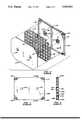
- FIG. 2is an exploded perspective of an end block in accordance with the present invention.
- FIG. 3is a front view of an assembled end block as shown in FIG. 2;
- FIG. 4is a back view of an assembled end block as shown in FIG. 2;
- FIG. 5is a sectional view of an end block taken along line 5--5 of FIG. 3.
- bipolar battery 100comprises a pair of end blocks 130, in accordance with the present invention, disposed exterior to a series of alternating separators 112 and electrodes 114, and sealed together to form a stack 120 of electrochemical cells.
- a pair of terminal electrodes 110are shown separated from end blocks 130 and stack 120.
- anolyte and catholyte inlet ducts 35 and 20, respectively, and respective anolyte and catholyte discharge ducts 45 and 40are positioned to facilitate passage of the aqueous anolyte and catholyte.
- Channels 116are provided on each side of electrodes 114 or separators 112 as desired for the proper flow of the fluid electrolyte.
- Battery 100is further provided with a pair of shunt tunnels 60 and 65 and preferably a removable shunt terminal 70 which helps minimize the effect of parasitic currents which often plague bipolar batteries of the zinc-bromine type.
- Commonly assigned application Ser. No. 241,714 entitled “Removable Protective Electrode in a Bipolar Battery", filed Sept. 8, 1988, now U.S. Pat. No. 4,929,325sets forth in detail such a removable terminal 70 and is therefore incorporated by way of reference herein.
- end block 130is depicted in exploded perspective with the three major parts thereof separated: a base member 132, a pair of end block inserts 134 and 136, and cover 138.
- Base member 132is essentially a thin planar member having a first "major surface” 140, as seen in FIG. 4.
- a second "major surface” 142is seen in FIGS. 2 and 5.
- a “major surface”may be defined as those surfaces on a flat object having the greatest area as opposed to the relatively small areas on the connecting sides.
- Major surface 140is essentially flat while major surface 142 is totally circumscribed by a wall 144 projecting outwardly from surface 142 except for corners 152.
- a dividing wall 146essentially bisects the area on surface 142 within the perimeters of wall 144 such that wall 146, together with wall 144 and surface 142, define a pair of cavities 148 and 150.
- Wall 146which may have a width of about 0.5 inches, acts as a reinforcing rib to provide desired rigidity to base 132 and end block 130.
- Inserts 134 and 136are housed within and have configurations complimentary to the dimensions of respective cavities 148 and 150.
- walls 144 and 146preferably extend outward from major surface 142 a distance equal to or slightly greater than the thickness of inserts 134 and 136.
- Flat cover member 138has a configuration which is preferably substantially identical to that defined by the outside edge of wall 144.
- respective corners 152 of base member 132remain exposed even after cover 138 is positioned on and secured to wall 144, thereby encapsulating inserts 134 and 136.
- corners 152serve as the supporting structure for the various anolyte/catholyte ducts and shunt tunnels.
- inserts 134 and 136are completely isolated from the electrolyte ducts and tunnels. This provides a further safeguard against any contact by the fluid electrolyte with the material comprising the inserts.
- each component of end block 130is provided with a pair of openings through which respective studs 50 and 55 may extend when the components thereof are assembled.
- Base member 132has a pair of rectangular shaped openings 158 and 160 circumscribed by respective rectangular shaped extensions or protrusions 159, 161 extending outward from major surface 142 centrally located within respective cavities 148 and 150.
- Complimentary openings 162 and 164are formed within respective inserts 134, 136 such that protrusions 159 and 161 extend therethrough in a snug fit relationship. Protrusions 159 and 161 thus serve to electrically insulate studs 50 and 55 from inserts 134 and 136.
- the length of the extension of protrusions 159, 161should be about the same or slightly greater than the thickness of inserts 134, 136, i.e. about the same as the extension of wall 144 and 146, such that the top surface of each protrusion abuts cover 138 about complimentary openings 154, 156 formed in cover 138.
- Base member 132 and cover 138are preferably fabricated from polyethylene, although other polyolefins such as polypropylene or polyolefin copolymers may be used as well.
- Various fillers and reinforcersmay be incorporated into the selected material to increase its strength. Fillers may be selected from any compatible materials, such as, for example, glass fibers, glass beads, or titanium dioxide. It has been determined that fillers up to about forty percent by weight of the selected material may be used without detrimentally affecting other desired characteristics of the base and cover.
- Inserts 134 and 136are fabricated from low density materials, for example, less than 8 pounds per cubic foot, having significant resistance to bending over the longest "linear dimension" of the end block.
- the term "linear dimension"is defined herein to mean the length or width measured along major surface 132 of the end block.
- a preferred materialis honey-combed aluminum laminated on either side with aluminum sheet, commercially available under the registered trademark Hexcel, from the Hexcel Company.
- Other materials having a density and weight approaching that of aluminummay also be utilized so long as the combined resistance against bending of the composite comprising end block 130 limits bending to less than about 0.005" under internal pressures within said battery of about 12 to 15 psi.
- certain other materialslike polyurethane, polypropylene, polyethylene, ceramics and graphite may also be employed.
- Both base 132 and cover 138are preferably made through an injection molding process, although compression molding techniques may be employed as well.
- inserts 134, 136may be placed within respective cavities 148, 150.
- Cover 138then is positioned in place and friction welded to the abutting parts of base 132.
- a weld bead(not shown) flanked by two flash traps may be positioned about the circumference of cover 138 or, alternatively, on wall 144 to facilitate friction welding of cover 138 to base 132.
- a weld line(not shown) may extend down wall 146 and a weld seal (not shown) about the cover abutting the top surfaces of protrusions 159, 161 may be used to provide additional support against bending.
- each substrate of the various battery componentsis made from a material such as polethylene, polypropylene, other polyolefins, or copolymers thereof, such that the components may be friction welded together about the entire peripheries thereof thereby forming an integral structure.
- the end blocks of the present inventionmay each be friction welded along the periphery of major surface 140 to an adjacent terminal electrode 110 to again provide the desired integral structural frame.
Landscapes
- Chemical & Material Sciences (AREA)
- Chemical Kinetics & Catalysis (AREA)
- Electrochemistry (AREA)
- General Chemical & Material Sciences (AREA)
- Engineering & Computer Science (AREA)
- Manufacturing & Machinery (AREA)
- Life Sciences & Earth Sciences (AREA)
- Sustainable Development (AREA)
- Sustainable Energy (AREA)
- Hybrid Cells (AREA)
Abstract
Description
Claims (23)
Priority Applications (1)
| Application Number | Priority Date | Filing Date | Title |
|---|---|---|---|
| US07/463,273US5002841A (en) | 1990-01-10 | 1990-01-10 | Composite end block for a battery |
Applications Claiming Priority (1)
| Application Number | Priority Date | Filing Date | Title |
|---|---|---|---|
| US07/463,273US5002841A (en) | 1990-01-10 | 1990-01-10 | Composite end block for a battery |
Publications (1)
| Publication Number | Publication Date |
|---|---|
| US5002841Atrue US5002841A (en) | 1991-03-26 |
Family
ID=23839526
Family Applications (1)
| Application Number | Title | Priority Date | Filing Date |
|---|---|---|---|
| US07/463,273Expired - Fee RelatedUS5002841A (en) | 1990-01-10 | 1990-01-10 | Composite end block for a battery |
Country Status (1)
| Country | Link |
|---|---|
| US (1) | US5002841A (en) |
Cited By (20)
| Publication number | Priority date | Publication date | Assignee | Title |
|---|---|---|---|---|
| US5114807A (en)* | 1990-04-30 | 1992-05-19 | California Institute Of Technology | Lightweight bipolar storage battery |
| US5308718A (en)* | 1993-01-15 | 1994-05-03 | Globe-Union Inc. | End block constructions for batteries |
| US5334464A (en)* | 1991-07-22 | 1994-08-02 | Bipolar Power Corporation | Lightweight battery plates |
| EP0620609A1 (en)* | 1993-03-26 | 1994-10-19 | Daimler-Benz Aktiengesellschaft | Electrochemical multicell-battery |
| US5605771A (en)* | 1995-10-26 | 1997-02-25 | Zbb Technologies, Inc. | Component design for an electric energy storing device |
| US5643696A (en)* | 1991-07-22 | 1997-07-01 | Bipolar Power Corporation | Battery plates with lightweight cores |
| US5645959A (en)* | 1992-08-20 | 1997-07-08 | Bipolar Power Corporation | Battery plates with self-passivating iron cores and mixed acid electrolyte |
| WO2002027818A1 (en)* | 2000-09-28 | 2002-04-04 | Powercell Corporation | Modular battery cell stack positioning system |
| US20080314913A1 (en)* | 2007-06-22 | 2008-12-25 | Apps William P | Container with reinforced base |
| US20090286134A1 (en)* | 2008-05-13 | 2009-11-19 | Hyundai Motor Company | End plate for fuel cell stack and method for manufacturing the same |
| US20110005962A1 (en)* | 2009-05-15 | 2011-01-13 | Dietheim Hirz | Tray or storage/transport-box floor |
| EP2432044A4 (en)* | 2009-05-14 | 2013-10-23 | Gs Yuasa Int Ltd | BATTERY ASSEMBLY |
| US20160204400A1 (en)* | 2015-01-08 | 2016-07-14 | Ford Global Technologies, Llc | Retention Assembly for Traction Battery Cell Array |
| WO2017132348A1 (en) | 2016-01-27 | 2017-08-03 | Ensync, Inc. | Improved electrolyte system for rechargeable flow battery |
| WO2017132346A1 (en) | 2016-01-27 | 2017-08-03 | Ensync, Inc. | Zinc complex compounds for rechargeable flow battery |
| WO2017132357A1 (en) | 2016-01-27 | 2017-08-03 | Ensync, Inc. | Surfactants for improved bromine dispersion in electrolyte flow battery solutions |
| WO2017132352A1 (en) | 2016-01-27 | 2017-08-03 | Ensync, Inc. | Process for joining incompatible materials and materials formed thereby |
| WO2018237381A3 (en)* | 2017-06-23 | 2019-02-21 | Advanced Battery Concepts, LLC | Reinforced bipolar battery assembly |
| US11888106B2 (en) | 2019-05-24 | 2024-01-30 | Advanced Battery Concepts, LLC | Battery assembly with integrated edge seal and methods of forming the seal |
| US12107253B2 (en) | 2018-11-15 | 2024-10-01 | Advanced Battery Concepts, LLC | Active materials useful in balancing power and energy density of a battery assembly |
Citations (4)
| Publication number | Priority date | Publication date | Assignee | Title |
|---|---|---|---|---|
| US3833424A (en)* | 1972-03-28 | 1974-09-03 | Licentia Gmbh | Gas fuel cell battery having bipolar graphite foam electrodes |
| US4689280A (en)* | 1986-02-20 | 1987-08-25 | Energy Research Corporation | Fuel cell stack end plate structure |
| US4818639A (en)* | 1985-04-08 | 1989-04-04 | Gas Research Institute | Molten carbonate electrolyte creepage barrier |
| US4826741A (en)* | 1987-06-02 | 1989-05-02 | Ergenics Power Systems, Inc. | Ion exchange fuel cell assembly with improved water and thermal management |
- 1990
- 1990-01-10USUS07/463,273patent/US5002841A/ennot_activeExpired - Fee Related
Patent Citations (4)
| Publication number | Priority date | Publication date | Assignee | Title |
|---|---|---|---|---|
| US3833424A (en)* | 1972-03-28 | 1974-09-03 | Licentia Gmbh | Gas fuel cell battery having bipolar graphite foam electrodes |
| US4818639A (en)* | 1985-04-08 | 1989-04-04 | Gas Research Institute | Molten carbonate electrolyte creepage barrier |
| US4689280A (en)* | 1986-02-20 | 1987-08-25 | Energy Research Corporation | Fuel cell stack end plate structure |
| US4826741A (en)* | 1987-06-02 | 1989-05-02 | Ergenics Power Systems, Inc. | Ion exchange fuel cell assembly with improved water and thermal management |
Cited By (28)
| Publication number | Priority date | Publication date | Assignee | Title |
|---|---|---|---|---|
| US5114807A (en)* | 1990-04-30 | 1992-05-19 | California Institute Of Technology | Lightweight bipolar storage battery |
| US5643696A (en)* | 1991-07-22 | 1997-07-01 | Bipolar Power Corporation | Battery plates with lightweight cores |
| US5334464A (en)* | 1991-07-22 | 1994-08-02 | Bipolar Power Corporation | Lightweight battery plates |
| US5645959A (en)* | 1992-08-20 | 1997-07-08 | Bipolar Power Corporation | Battery plates with self-passivating iron cores and mixed acid electrolyte |
| US5308718A (en)* | 1993-01-15 | 1994-05-03 | Globe-Union Inc. | End block constructions for batteries |
| EP0620609A1 (en)* | 1993-03-26 | 1994-10-19 | Daimler-Benz Aktiengesellschaft | Electrochemical multicell-battery |
| AU702188B2 (en)* | 1995-10-26 | 1999-02-18 | Zbb Technologies Inc. | Component design for an electric energy storing device |
| WO1997015956A1 (en)* | 1995-10-26 | 1997-05-01 | Zbb Technologies Inc. | Component design for an electric energy storing device |
| US5605771A (en)* | 1995-10-26 | 1997-02-25 | Zbb Technologies, Inc. | Component design for an electric energy storing device |
| WO2002027818A1 (en)* | 2000-09-28 | 2002-04-04 | Powercell Corporation | Modular battery cell stack positioning system |
| US20080314913A1 (en)* | 2007-06-22 | 2008-12-25 | Apps William P | Container with reinforced base |
| US8348088B2 (en) | 2007-06-22 | 2013-01-08 | Rehrig Pacific Company | Container with reinforced base |
| US20090286134A1 (en)* | 2008-05-13 | 2009-11-19 | Hyundai Motor Company | End plate for fuel cell stack and method for manufacturing the same |
| TWI476980B (en)* | 2009-05-14 | 2015-03-11 | Gs Yuasa Int Ltd | Combination battery |
| US9929386B2 (en) | 2009-05-14 | 2018-03-27 | Gs Yuasa International Ltd. | Battery assembly |
| EP2432044A4 (en)* | 2009-05-14 | 2013-10-23 | Gs Yuasa Int Ltd | BATTERY ASSEMBLY |
| US8470225B2 (en)* | 2009-05-15 | 2013-06-25 | Fritz Schaefer Gmbh | Tray or storage/transport-box floor |
| US20110005962A1 (en)* | 2009-05-15 | 2011-01-13 | Dietheim Hirz | Tray or storage/transport-box floor |
| US20160204400A1 (en)* | 2015-01-08 | 2016-07-14 | Ford Global Technologies, Llc | Retention Assembly for Traction Battery Cell Array |
| CN105789507A (en)* | 2015-01-08 | 2016-07-20 | 福特全球技术公司 | Retention Assembly For Traction Battery Cell Array |
| US9583747B2 (en)* | 2015-01-08 | 2017-02-28 | Ford Global Technologies, Llc | Retention assembly for traction battery cell array |
| WO2017132348A1 (en) | 2016-01-27 | 2017-08-03 | Ensync, Inc. | Improved electrolyte system for rechargeable flow battery |
| WO2017132346A1 (en) | 2016-01-27 | 2017-08-03 | Ensync, Inc. | Zinc complex compounds for rechargeable flow battery |
| WO2017132357A1 (en) | 2016-01-27 | 2017-08-03 | Ensync, Inc. | Surfactants for improved bromine dispersion in electrolyte flow battery solutions |
| WO2017132352A1 (en) | 2016-01-27 | 2017-08-03 | Ensync, Inc. | Process for joining incompatible materials and materials formed thereby |
| WO2018237381A3 (en)* | 2017-06-23 | 2019-02-21 | Advanced Battery Concepts, LLC | Reinforced bipolar battery assembly |
| US12107253B2 (en) | 2018-11-15 | 2024-10-01 | Advanced Battery Concepts, LLC | Active materials useful in balancing power and energy density of a battery assembly |
| US11888106B2 (en) | 2019-05-24 | 2024-01-30 | Advanced Battery Concepts, LLC | Battery assembly with integrated edge seal and methods of forming the seal |
Similar Documents
| Publication | Publication Date | Title |
|---|---|---|
| US5002841A (en) | Composite end block for a battery | |
| EP1568089B1 (en) | A bipolar battery and a method for manufacturing a bipolar battery | |
| US7258949B2 (en) | Bipolar battery and a method for manufacturing a bipolar battery | |
| CA2450510C (en) | Cell stack for redox flow battery | |
| JP2898192B2 (en) | Battery plate compression case assembly structure | |
| US5326656A (en) | Bipolar battery electrode | |
| US3941615A (en) | Battery construction | |
| US4022951A (en) | Battery construction | |
| JPH0757768A (en) | Bipolar battery, method of assembling the same, and method of forming housing | |
| KR102513429B1 (en) | Reinforced bipolar battery assembly | |
| CN103959507A (en) | Bipolar battery assembly | |
| JPH1074530A (en) | Fuel cell and separator for fuel cell | |
| US6468318B1 (en) | Case partition design for continuous plate strap batteries | |
| US5344727A (en) | Bipolar battery electrode | |
| WO2021136015A1 (en) | Method for manufacturing bipolar battery, method for manufacturing bipolar plate thereof, and method for manufacturing unipolar plate thereof | |
| US4209575A (en) | Multi-cell batteries | |
| EP3555935B1 (en) | A battery module casing, a battery module and a battery | |
| CA1046138A (en) | Rechargeable battery having a plurality of frames supporting active material and separators | |
| KR102858835B1 (en) | Flow battery | |
| JP2677137B2 (en) | Thin sealed storage battery | |
| JP2853296B2 (en) | Bipolar electrode plate for stacked batteries | |
| JPS6158159A (en) | Secondary battery | |
| HK40016095A (en) | A battery module casing, a battery module and a battery | |
| HK40016095B (en) | A battery module casing, a battery module and a battery | |
| JPS6158161A (en) | Manufacture of frame-mounted barrier membrane for stacked battery |
Legal Events
| Date | Code | Title | Description |
|---|---|---|---|
| AS | Assignment | Owner name:GLOBE-UNION INC., WISCONSIN Free format text:ASSIGNMENT OF ASSIGNORS INTEREST.;ASSIGNORS:BELONGIA, DAVID C.;ZAGRODNIK, JEFFREY P.;BOLSTAD, JAMES J.;AND OTHERS;REEL/FRAME:005215/0097 Effective date:19900102 | |
| FEPP | Fee payment procedure | Free format text:PAYOR NUMBER ASSIGNED (ORIGINAL EVENT CODE: ASPN); ENTITY STATUS OF PATENT OWNER: SMALL ENTITY | |
| FPAY | Fee payment | Year of fee payment:4 | |
| AS | Assignment | Owner name:JOHNSON CONTROLS BATTERY GROUP, INC., WISCONSIN Free format text:ASSIGNMENT OF ASSIGNORS INTEREST;ASSIGNOR:GLOBE UNION, INC.;REEL/FRAME:007147/0326 Effective date:19940930 Owner name:ZBB TECHNOLOGIES, INC., WISCONSIN Free format text:ASSIGNMENT OF ASSIGNORS INTEREST;ASSIGNOR:JOHNSON CONTROLS BATTERY GROUP, INC.;REEL/FRAME:007160/0897 Effective date:19940930 | |
| FEPP | Fee payment procedure | Free format text:PAT HOLDER CLAIMS SMALL ENTITY STATUS - SMALL BUSINESS (ORIGINAL EVENT CODE: SM02); ENTITY STATUS OF PATENT OWNER: SMALL ENTITY | |
| FPAY | Fee payment | Year of fee payment:8 | |
| REMI | Maintenance fee reminder mailed | ||
| FPAY | Fee payment | Year of fee payment:12 | |
| LAPS | Lapse for failure to pay maintenance fees | ||
| SULP | Surcharge for late payment | Year of fee payment:11 | |
| FP | Lapsed due to failure to pay maintenance fee | Effective date:20030326 | |
| AS | Assignment | Owner name:CTI CAPITAL MANAGEMENT AS COLLATERAL AGENT, FLORID Free format text:SECURITY INTEREST;ASSIGNOR:ZBB TECHNOLOGIES, INC.;REEL/FRAME:017996/0326 Effective date:20060614 | |
| AS | Assignment | Owner name:ZBB TECHNOLOGIES, INC., WISCONSIN Free format text:RELEASE OF SECURITY INTERESTS;ASSIGNOR:CTI CAPITAL MANAGEMENT AS COLLATERAL AGENT;REEL/FRAME:020174/0779 Effective date:20071126 | |
| STCH | Information on status: patent discontinuation | Free format text:PATENT EXPIRED DUE TO NONPAYMENT OF MAINTENANCE FEES UNDER 37 CFR 1.362 |