US5002388A - Optical distance measuring apparatus having a measurement error compensating function - Google Patents
Optical distance measuring apparatus having a measurement error compensating functionDownload PDFInfo
- Publication number
- US5002388A US5002388AUS07/323,305US32330589AUS5002388AUS 5002388 AUS5002388 AUS 5002388AUS 32330589 AUS32330589 AUS 32330589AUS 5002388 AUS5002388 AUS 5002388A
- Authority
- US
- United States
- Prior art keywords
- optical path
- amplitude modulated
- distance measuring
- modulated light
- light
- Prior art date
- Legal status (The legal status is an assumption and is not a legal conclusion. Google has not performed a legal analysis and makes no representation as to the accuracy of the status listed.)
- Expired - Lifetime
Links
- 230000003287optical effectEffects0.000titleclaimsabstractdescription135
- 238000005259measurementMethods0.000titleclaimsabstractdescription54
- 238000012935AveragingMethods0.000claims3
- 230000005674electromagnetic inductionEffects0.000abstractdescription13
- 239000013307optical fiberSubstances0.000description11
- 230000004907fluxEffects0.000description5
- 238000007796conventional methodMethods0.000description3
- 230000008859changeEffects0.000description2
- 238000010586diagramMethods0.000description2
- 230000000694effectsEffects0.000description2
- 230000007423decreaseEffects0.000description1
- 239000003989dielectric materialSubstances0.000description1
- 238000002474experimental methodMethods0.000description1
- 239000000835fiberSubstances0.000description1
- 239000011521glassSubstances0.000description1
- 239000011810insulating materialSubstances0.000description1
- 238000013208measuring procedureMethods0.000description1
- 238000000034methodMethods0.000description1
- 238000012986modificationMethods0.000description1
- 230000004048modificationEffects0.000description1
- 239000010453quartzSubstances0.000description1
- VYPSYNLAJGMNEJ-UHFFFAOYSA-Nsilicon dioxideInorganic materialsO=[Si]=OVYPSYNLAJGMNEJ-UHFFFAOYSA-N0.000description1
Images

Classifications
- G—PHYSICS
- G01—MEASURING; TESTING
- G01C—MEASURING DISTANCES, LEVELS OR BEARINGS; SURVEYING; NAVIGATION; GYROSCOPIC INSTRUMENTS; PHOTOGRAMMETRY OR VIDEOGRAMMETRY
- G01C3/00—Measuring distances in line of sight; Optical rangefinders
- G01C3/02—Details
- G01C3/06—Use of electric means to obtain final indication
- G01C3/08—Use of electric radiation detectors
Definitions
- the present inventionrelates to an optical distance measuring apparatus capable of compensating for measurement error due to electromagnetic induction noise which would lower the accuracy in distance measurement by the optical distance measuring apparatus.
- an optical distance measuring apparatusgenerally has an error which periodically increases and decreases in accordance with the distance to be measured. Such an error is generally called “measurement error” since it influences the distance measurement.
- measurement errorhas been compensated by an electric means.
- the conventinal method for error compensationuses an electric means.
- the conventional methodcannot eliminate the drift in electromagnetic induction noise due to, for example, temperature change when such drift arises after completion of adjustment of the apparatus.
- much timeis required for the conventional method to carry out highly accurate compensation for the measurement error.
- an object of the present inventionto provide an optical distance measuring apparatus having a measurement error compensating function which can eliminate the above-mentioned problems inherent in the prior art and can also easily obtain measurement of high-accuracy distance measurement.
- an optical distance measuring apparatushaving a measurement error compensating function comprising: a light emission means for emitting amplitide modulated light toward a target the distance to which is to be measured; a light receiving means for receiving the amplitude modulated light reflected by said target; an internal reference optical path for directly leading said amplitude modulated light from said light emission means to said light receiving means; an external distance measuring optical path for directing said amplitude modulated light from said emission means toward said target and for leading the amplitude modulated light reflected therefrom to said receiving means; an optical path switching means for selecting one or the other of said internal reference optical path and said external distance measuring optical path and for switching so that said amplitude modulated light from said light emission means can pass along the selected optical path; an optical path extension means connected to part of said internal reference optical path and external distance measuring optical path for extending their lengths by a predetermined length; a phase detecting means for detecting the phase of an output signal from said light receiving means; and
- the distance X from the optical distance measuring apparatus to a corner-cube prism(this prism corresponds to an external target) is represented on the x-axis and the measurement error ⁇ L(X) of the measured distance value relative to the real distance value is represented on the y-axis as will be noted, the measurement error appears as a periodically repeated sinusoidal curve.
- the wavelength of 15 MHz amplitude modulated lightis 20 meters. If the corner-cube prism is set 10 meters from the optical distance measuring apparatus (i.e. if the distance to be measured is 10 meters), the round-trip distance of 20 meters between the apparatus and the corner-cube prism coincides with the wavelength of 20 meters of the amplitude modulated light.
- the distance to be measured(1/2 the round-trip distance between the optical distance measuring apparatus and the corner-cube prism) corresponds to 1/2 the wavelength of the amplitude modulated light which causes the error in the distance for measurement.
- the [above-mentioned] measurement error curveis a sinusoidal curve having a period 10 meters. From the nature of sinusoidal functions, the measurement error ⁇ L(g) at a distance "g" meters equals a measurement error ⁇ L (g+10) at a distance (g+10) meters, that is,
- the absolute value of the measurement error ⁇ L (g+5) at a distance (g+5) metersequals the measurement error ⁇ L (g) but has a negative sign(-), that is,
- the distance from the apparatus to the targetis obtained from the difference between the length of the "external optical path" to the corner-cube prism (i.e. the external target) and the length of an "internal reference optical path".
- the inventors found that the measurement error curve giving the change in measurement error relative to the measured distancecan be represented by a sinusoidal curve having a wavelength equal to the wavelength of the modulating frequency of the amplitude modulated light used in the optical distance measuring apparatus for precision measurement. Then by setting the length of the optical path of the optical path extension means to, for example, 1/2 the wavelength of the amplitude modulated light, obtaining the phase difference signals output by the phase detector and representing the differences in the internal and external optical paths between the case in which the optical path extension means is connected and the case in which it is unconnected, and then obtaining the arithmetical means of the phrase difference, it is possible to cancel out the measurement error by the periodicity of the measurement error curve and the predetermined length of the optical path extension means. Thus the measurement error can be compensated for and therefore a measured value measuremnt error can be obtained from the distance measuring means.
- FIG. 1is a diagram showing, as a periodical function of the measured distance, a measurement error due to electromagnetic induction noise, which is one factor lowering the measurement accuracy of the optical distance measuring apparatus;
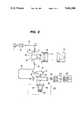
- FIG. 2is a block diagram showing the structure of an optical distance measuring apparatus of the present invention.
- a light emission means 1emits two kinds of light waves, a light wave for accurate measurement having a modulation frequency of 15 MHz (wavelenght of 20 meters) and a light wave for rough measurement having a frequency of 75 KHz (wavelength of 2 km).
- An 15 MHz amplitude modulated lightis used in the preferred embodiment of the present invention.
- the amplitude modulated light emitted from the light emission means 1is converged by a condenser lens 2 to one end of an optical fiber 3 and then arrives at the other end of the optical fiber 3.
- a prism Pis arranged opposite to said other end of the optical fiber 3 and a shutter 4 is positioned therebetween.
- the shutter 4constitutes a first optical path switching means for selectively switching between an external distance measuring light or an internal reference light.
- the amplitude modulated light reflected by the reflecting surface 5 of the prism Ptravels along an optical path 7 for external distance measurement. Then the light passes through an objective lens 8 and enters a corner-cube prism 9 which constitutes as an external target.
- the objective lens 8makes the incident light parallel.
- the light incident on the corner-cube prism 9is reflected by it and then again passes through the objective lens 8 and is reflected by a reflecting surface 6 of the prism P and arrives at a point Q.
- the amplitude modulated light entering the prism Pis r eflected by an internal reflecting surface 10 thereof and travels along an internal reference optical path 11 and then arrives at the point Q.
- an optical path switching prism 17which constitutes second optical path switching means for switching between a standard optical path or an extended optical path, is in the position "a" shown by a solid line in FIG. 2 and does not interrupt the luminous flux between the lenses 13 and 14.
- the optical path switching prism 17When the optical path switching prism 17 is in a position "b" shown by a phantom line, the parallel luminous flux from the lens 13 is reflected by a reflecting surface 21 and then is converged by a lens 15 to form an image on its focal point on which one end of an optical fiber 18 such as a "Gi" (Graded-index) type fiber is disposed. A lens 16 is disposed on the other end of the "Gi" type optical fiber 18. These lenses 15 and 16 and optical fiber 18 constitute an optical path extension means 20.
- the length of the optical path of the optical path extention means 20is determined to be equal to 1/2 the 20 m wavelength of the 15 MHz amplitude modulated light for precision measurement. Specifically, the length of the optical path is determined to be 10 m, and the measured distance to be 5 m.
- the optical path switching prism 17when the optical path switching prism 17 is switched to the position "b", the parallel luminous flux from the lens 13 is reflected by the reflecting surfaces 21 of the prism 17 and the n enters the lens 15. Then the light converged by the lens 15 travels through the optical fiber 18 and the lens 16 and then enters the lens 14 after having been reflected by a reflecting surface 21 of the prism 17.
- the luminous flux emitted from the lens 14is converged on the light receiving means 19 (disposed at the focal point of the lens 14). In such a way, the light travels along a longer optical path while passing through the optical path extension means 20 when the prism 17 is in the position "b". On the other hand, the light travels along a shorter optical path without passing through the optical path extension means 20 when the prism 17 is in the position "a".
- any combination of extended and unextended internal reference optical paths and external distance measuring optical pathcan be freely selected by appropriately switching the shutter 4 constituting the first optical path switching means and/or the optical path switching prism 17 constituting the second optical path switching means.
- a distance measuring means 22 connected to the phase detecting means 23calculated the distance to the corner-cube prism (i.e. the external target) 9 based upon the phase difference detected by the phase detecting means 23 and corresponding to the difference in length between the selected optical paths.
- optical distance measuring apparatus of the present inventionwill now be described. As shown in the following table, four kinds of separate optical paths L can be obtained by appropriately positioning the shutter 4 and the switching prism 17. These four optical paths L also represent respective lengths of the optical path.
- the measured distance from the apparatus to the corner-cube prism (i.e. the external target) 9can generally be obtained by subtracting the measured distance value of the "internal reference optical path" from the measured distance value of the "external optical path”.
- the measured value Lis defined as follows: ##EQU1##
- a value of [L est .+5 -L int . ]is measured.
- the value of thereofcorresponds to a distance longer than the real distance by 5 meters (which corresponds to the increment of optical path in the optical path extension means 20.) That is, the value corresponds to that of a position H situated 5 meters away from the point G. Since the distance measuring error ⁇ L(b) (for a distance "b" meters from the reference point to the position H is for the position H) situated 5 meters (1/2 wavelength) away from the position G, the magnitude thereof is equal to ⁇ L(a) and the sign thereof is inverse. Accordingly the value L' of [L ext .+5 -L int . ] measured by the optical distance measuring apparatus is obtained as follows: ##EQU2## Also
- the cancellation of the error due to electromagnetic induction noisecan also be carried out as following.
- the following matterscan be understood by comparing L ext ., L int ., L ext .+5 and L int .+5 with each other.
- L ext .+5When comparing L ext . with L ext .+5, it will be appreciated that the length of L ext .+5 is longer than L ext . by 5 meters and accordingly L ext .+5 includes electromagnetic induction noise which has a same magnitude as the electromagnetic induction noise included in L ext . and also has a sign inverse thereto.
- equations 8 and 9demonstrate how the distance measuring means 22 averages both the half-wavelength phase-delayed optical lengths and the non-phase-delayed optical lengths.
- the actual measuring procedurecan be carried out by firstly placing the optical path switching prism 17 on the positions "a” and “b” and then detecting at respective positions "a” and “b” the phase difference corresponding to the difference in optical path between the external optical path and internal reference optical path and finally obtaining from the distance measuring means 22 the value of the arithmetical mean of the detected phase difference.
- the length of optical path in the optical path extension means 20is selected as 1/2 the 20 m wavelength of the modulated light for precision measurement in the above-mentioned embodiment, the same effect can be obtained by using a value of the extended length of optical length in the means 20 which is obtained by multiplying 1/2 the wavelength of the amplitude modulated light for precision measurement by an odd number. This is because the measurement error curve can be represented by a sinusoidal curve having a wavelength equal to 1/2 the distance measuring wavelength.
- the compensation for the measurement errorcan be rapidly and easily carried out in an automatic manner as compared with the conventional method using an electric means.
- the optical fiber used as part of the optical system of the present apparatusis made of a dielectric material (i.e. insulating material) such as quartz or glass, the apparatus is not influenced at all by electromagnetic induction noise which would cause measurement error.
- a dielectric materiali.e. insulating material
Landscapes
- Physics & Mathematics (AREA)
- Electromagnetism (AREA)
- Engineering & Computer Science (AREA)
- General Physics & Mathematics (AREA)
- Radar, Positioning & Navigation (AREA)
- Remote Sensing (AREA)
- Optical Radar Systems And Details Thereof (AREA)
Abstract
Description
ΔL(g)=ΔL(g+10) (1)
ΔL(g+5)=-ΔL(g) (2)
______________________________________ position of optical path selected by kind/length ofoptical path prism 17shutter 4 ______________________________________ L.sub.ext. a ext.optical path 7 L.sub.int. a int. ref. optical path 11 L.sub.(ext. +5) b ext.optical path 7 L.sub.(int. +5) b int. ref. optical path 11 ______________________________________
b=a+5 (5)
ΔL(b)=ΔL(a+5)=-ΔL(a) (6)
Claims (3)
Applications Claiming Priority (2)
| Application Number | Priority Date | Filing Date | Title |
|---|---|---|---|
| JP63062822AJP2717408B2 (en) | 1988-03-16 | 1988-03-16 | Lightwave ranging device with linearity error correction function |
| JP63-62822 | 1988-03-16 |
Publications (1)
| Publication Number | Publication Date |
|---|---|
| US5002388Atrue US5002388A (en) | 1991-03-26 |
Family
ID=13211409
Family Applications (1)
| Application Number | Title | Priority Date | Filing Date |
|---|---|---|---|
| US07/323,305Expired - LifetimeUS5002388A (en) | 1988-03-16 | 1989-03-15 | Optical distance measuring apparatus having a measurement error compensating function |
Country Status (2)
| Country | Link |
|---|---|
| US (1) | US5002388A (en) |
| JP (1) | JP2717408B2 (en) |
Cited By (22)
| Publication number | Priority date | Publication date | Assignee | Title |
|---|---|---|---|---|
| US5208642A (en)* | 1992-04-29 | 1993-05-04 | Optec Co. Ltd. | Electro-optical distance meter |
| US5311271A (en)* | 1992-01-21 | 1994-05-10 | Dme/Golf, Inc. | Golf course range finder |
| US5737068A (en)* | 1995-02-08 | 1998-04-07 | Asahi Kogaku Kogyo Kabushiki Kaisha | Electronic distance measuring device using a phase difference detection method |
| US5742379A (en)* | 1995-11-29 | 1998-04-21 | Reifer; Michael H. | Device and method for electronically measuring distances |
| US5921257A (en)* | 1996-04-24 | 1999-07-13 | Steag Microtech Gmbh | Device for treating substrates in a fluid container |
| US20110032509A1 (en)* | 2009-08-07 | 2011-02-10 | Faro Technologies, Inc. | Absolute distance meter with optical switch |
| WO2012154322A1 (en) | 2011-04-15 | 2012-11-15 | Faro Technologies, Inc. | Absolute distance meter that uses a fiber-optic switch to reduce drift |
| USD688577S1 (en) | 2012-02-21 | 2013-08-27 | Faro Technologies, Inc. | Laser tracker |
| US8781780B2 (en) | 2009-01-22 | 2014-07-15 | Kabushiki Kaisha Topcon | Electro-optical distance measuring method and electro-optical distance measuring device |
| US8902408B2 (en) | 2011-02-14 | 2014-12-02 | Faro Technologies Inc. | Laser tracker used with six degree-of-freedom probe having separable spherical retroreflector |
| US9007601B2 (en) | 2010-04-21 | 2015-04-14 | Faro Technologies, Inc. | Automatic measurement of dimensional data with a laser tracker |
| US9041914B2 (en) | 2013-03-15 | 2015-05-26 | Faro Technologies, Inc. | Three-dimensional coordinate scanner and method of operation |
| US9164173B2 (en) | 2011-04-15 | 2015-10-20 | Faro Technologies, Inc. | Laser tracker that uses a fiber-optic coupler and an achromatic launch to align and collimate two wavelengths of light |
| US9377885B2 (en) | 2010-04-21 | 2016-06-28 | Faro Technologies, Inc. | Method and apparatus for locking onto a retroreflector with a laser tracker |
| US9395174B2 (en) | 2014-06-27 | 2016-07-19 | Faro Technologies, Inc. | Determining retroreflector orientation by optimizing spatial fit |
| US9400170B2 (en) | 2010-04-21 | 2016-07-26 | Faro Technologies, Inc. | Automatic measurement of dimensional data within an acceptance region by a laser tracker |
| US9453913B2 (en) | 2008-11-17 | 2016-09-27 | Faro Technologies, Inc. | Target apparatus for three-dimensional measurement system |
| US9482755B2 (en) | 2008-11-17 | 2016-11-01 | Faro Technologies, Inc. | Measurement system having air temperature compensation between a target and a laser tracker |
| US9482529B2 (en) | 2011-04-15 | 2016-11-01 | Faro Technologies, Inc. | Three-dimensional coordinate scanner and method of operation |
| US9638507B2 (en) | 2012-01-27 | 2017-05-02 | Faro Technologies, Inc. | Measurement machine utilizing a barcode to identify an inspection plan for an object |
| US9686532B2 (en) | 2011-04-15 | 2017-06-20 | Faro Technologies, Inc. | System and method of acquiring three-dimensional coordinates using multiple coordinate measurement devices |
| US9772394B2 (en) | 2010-04-21 | 2017-09-26 | Faro Technologies, Inc. | Method and apparatus for following an operator and locking onto a retroreflector with a laser tracker |
Families Citing this family (1)
| Publication number | Priority date | Publication date | Assignee | Title |
|---|---|---|---|---|
| JP2550866B2 (en)* | 1993-06-28 | 1996-11-06 | 日本電気株式会社 | Lightwave ranging device |
Citations (4)
| Publication number | Priority date | Publication date | Assignee | Title |
|---|---|---|---|---|
| US3619058A (en)* | 1969-11-24 | 1971-11-09 | Hewlett Packard Co | Distance measuring apparatus |
| US3740141A (en)* | 1971-09-20 | 1973-06-19 | Laser Systems & Electronics | Timing and measuring methods and means for laser distance measurements |
| US3778159A (en)* | 1970-03-10 | 1973-12-11 | Laser Systems & Electronics | Distance measuring apparatus and method utilizing phase comparison of modulated light beams |
| US4560271A (en)* | 1982-04-08 | 1985-12-24 | Tokyo Kogaku Kikai Kabushiki Kaisha | Optical distance-measuring method and apparatus therefor |
- 1988
- 1988-03-16JPJP63062822Apatent/JP2717408B2/ennot_activeExpired - Lifetime
- 1989
- 1989-03-15USUS07/323,305patent/US5002388A/ennot_activeExpired - Lifetime
Patent Citations (4)
| Publication number | Priority date | Publication date | Assignee | Title |
|---|---|---|---|---|
| US3619058A (en)* | 1969-11-24 | 1971-11-09 | Hewlett Packard Co | Distance measuring apparatus |
| US3778159A (en)* | 1970-03-10 | 1973-12-11 | Laser Systems & Electronics | Distance measuring apparatus and method utilizing phase comparison of modulated light beams |
| US3740141A (en)* | 1971-09-20 | 1973-06-19 | Laser Systems & Electronics | Timing and measuring methods and means for laser distance measurements |
| US4560271A (en)* | 1982-04-08 | 1985-12-24 | Tokyo Kogaku Kikai Kabushiki Kaisha | Optical distance-measuring method and apparatus therefor |
Cited By (48)
| Publication number | Priority date | Publication date | Assignee | Title |
|---|---|---|---|---|
| US5311271A (en)* | 1992-01-21 | 1994-05-10 | Dme/Golf, Inc. | Golf course range finder |
| US5208642A (en)* | 1992-04-29 | 1993-05-04 | Optec Co. Ltd. | Electro-optical distance meter |
| US5737068A (en)* | 1995-02-08 | 1998-04-07 | Asahi Kogaku Kogyo Kabushiki Kaisha | Electronic distance measuring device using a phase difference detection method |
| US5742379A (en)* | 1995-11-29 | 1998-04-21 | Reifer; Michael H. | Device and method for electronically measuring distances |
| US5921257A (en)* | 1996-04-24 | 1999-07-13 | Steag Microtech Gmbh | Device for treating substrates in a fluid container |
| US9482755B2 (en) | 2008-11-17 | 2016-11-01 | Faro Technologies, Inc. | Measurement system having air temperature compensation between a target and a laser tracker |
| US9453913B2 (en) | 2008-11-17 | 2016-09-27 | Faro Technologies, Inc. | Target apparatus for three-dimensional measurement system |
| US8781780B2 (en) | 2009-01-22 | 2014-07-15 | Kabushiki Kaisha Topcon | Electro-optical distance measuring method and electro-optical distance measuring device |
| US20110032509A1 (en)* | 2009-08-07 | 2011-02-10 | Faro Technologies, Inc. | Absolute distance meter with optical switch |
| US8570493B2 (en) | 2009-08-07 | 2013-10-29 | Faro Technologies, Inc. | Absolute distance meter that uses a fiber-optic switch to reduce drift |
| US8659749B2 (en) | 2009-08-07 | 2014-02-25 | Faro Technologies, Inc. | Absolute distance meter with optical switch |
| DE102010038955B4 (en) | 2009-08-07 | 2019-08-01 | Faro Technologies, Inc. | Absolute distance measuring device with optical switch |
| DE102010038955A1 (en) | 2009-08-07 | 2011-02-24 | Faro Technologies, Inc., Lake Mary | Absolute distance measuring device with optical switch |
| US10209059B2 (en) | 2010-04-21 | 2019-02-19 | Faro Technologies, Inc. | Method and apparatus for following an operator and locking onto a retroreflector with a laser tracker |
| US9772394B2 (en) | 2010-04-21 | 2017-09-26 | Faro Technologies, Inc. | Method and apparatus for following an operator and locking onto a retroreflector with a laser tracker |
| US10480929B2 (en) | 2010-04-21 | 2019-11-19 | Faro Technologies, Inc. | Method and apparatus for following an operator and locking onto a retroreflector with a laser tracker |
| US9400170B2 (en) | 2010-04-21 | 2016-07-26 | Faro Technologies, Inc. | Automatic measurement of dimensional data within an acceptance region by a laser tracker |
| US9377885B2 (en) | 2010-04-21 | 2016-06-28 | Faro Technologies, Inc. | Method and apparatus for locking onto a retroreflector with a laser tracker |
| US9146094B2 (en) | 2010-04-21 | 2015-09-29 | Faro Technologies, Inc. | Automatic measurement of dimensional data with a laser tracker |
| US9007601B2 (en) | 2010-04-21 | 2015-04-14 | Faro Technologies, Inc. | Automatic measurement of dimensional data with a laser tracker |
| US8902408B2 (en) | 2011-02-14 | 2014-12-02 | Faro Technologies Inc. | Laser tracker used with six degree-of-freedom probe having separable spherical retroreflector |
| US9157987B2 (en) | 2011-04-15 | 2015-10-13 | Faro Technologies, Inc. | Absolute distance meter based on an undersampling method |
| US9494412B2 (en) | 2011-04-15 | 2016-11-15 | Faro Technologies, Inc. | Diagnosing multipath interference and eliminating multipath interference in 3D scanners using automated repositioning |
| US9151830B2 (en) | 2011-04-15 | 2015-10-06 | Faro Technologies, Inc. | Six degree-of-freedom laser tracker that cooperates with a remote structured-light scanner |
| US8908154B2 (en) | 2011-04-15 | 2014-12-09 | Faro Technologies, Inc. | Laser tracker that combines two different wavelengths with a fiber-optic coupler |
| US9164173B2 (en) | 2011-04-15 | 2015-10-20 | Faro Technologies, Inc. | Laser tracker that uses a fiber-optic coupler and an achromatic launch to align and collimate two wavelengths of light |
| US9207309B2 (en) | 2011-04-15 | 2015-12-08 | Faro Technologies, Inc. | Six degree-of-freedom laser tracker that cooperates with a remote line scanner |
| US8848203B2 (en) | 2011-04-15 | 2014-09-30 | Faro Technologies, Inc. | Six degree-of-freedom laser tracker that cooperates with a remote projector to convey information |
| US10578423B2 (en) | 2011-04-15 | 2020-03-03 | Faro Technologies, Inc. | Diagnosing multipath interference and eliminating multipath interference in 3D scanners using projection patterns |
| US8842259B2 (en) | 2011-04-15 | 2014-09-23 | Faro Technologies, Inc. | Laser tracker with enhanced handling features |
| US9448059B2 (en) | 2011-04-15 | 2016-09-20 | Faro Technologies, Inc. | Three-dimensional scanner with external tactical probe and illuminated guidance |
| US9453717B2 (en) | 2011-04-15 | 2016-09-27 | Faro Technologies, Inc. | Diagnosing multipath interference and eliminating multipath interference in 3D scanners using projection patterns |
| US10302413B2 (en) | 2011-04-15 | 2019-05-28 | Faro Technologies, Inc. | Six degree-of-freedom laser tracker that cooperates with a remote sensor |
| US9482746B2 (en) | 2011-04-15 | 2016-11-01 | Faro Technologies, Inc. | Six degree-of-freedom laser tracker that cooperates with a remote sensor |
| WO2012154322A1 (en) | 2011-04-15 | 2012-11-15 | Faro Technologies, Inc. | Absolute distance meter that uses a fiber-optic switch to reduce drift |
| US8681320B2 (en) | 2011-04-15 | 2014-03-25 | Faro Technologies, Inc. | Gimbal instrument having a prealigned and replaceable optics bench |
| US9482529B2 (en) | 2011-04-15 | 2016-11-01 | Faro Technologies, Inc. | Three-dimensional coordinate scanner and method of operation |
| US10267619B2 (en) | 2011-04-15 | 2019-04-23 | Faro Technologies, Inc. | Three-dimensional coordinate scanner and method of operation |
| US8537376B2 (en) | 2011-04-15 | 2013-09-17 | Faro Technologies, Inc. | Enhanced position detector in laser tracker |
| US9686532B2 (en) | 2011-04-15 | 2017-06-20 | Faro Technologies, Inc. | System and method of acquiring three-dimensional coordinates using multiple coordinate measurement devices |
| US8558992B2 (en) | 2011-04-15 | 2013-10-15 | Faro Technologies, Inc. | Laser tracker with enhanced illumination indicators |
| US10119805B2 (en) | 2011-04-15 | 2018-11-06 | Faro Technologies, Inc. | Three-dimensional coordinate scanner and method of operation |
| US9638507B2 (en) | 2012-01-27 | 2017-05-02 | Faro Technologies, Inc. | Measurement machine utilizing a barcode to identify an inspection plan for an object |
| USD688577S1 (en) | 2012-02-21 | 2013-08-27 | Faro Technologies, Inc. | Laser tracker |
| USD705678S1 (en) | 2012-02-21 | 2014-05-27 | Faro Technologies, Inc. | Laser tracker |
| US9482514B2 (en) | 2013-03-15 | 2016-11-01 | Faro Technologies, Inc. | Diagnosing multipath interference and eliminating multipath interference in 3D scanners by directed probing |
| US9041914B2 (en) | 2013-03-15 | 2015-05-26 | Faro Technologies, Inc. | Three-dimensional coordinate scanner and method of operation |
| US9395174B2 (en) | 2014-06-27 | 2016-07-19 | Faro Technologies, Inc. | Determining retroreflector orientation by optimizing spatial fit |
Also Published As
| Publication number | Publication date |
|---|---|
| JP2717408B2 (en) | 1998-02-18 |
| JPH01235889A (en) | 1989-09-20 |
Similar Documents
| Publication | Publication Date | Title |
|---|---|---|
| US5002388A (en) | Optical distance measuring apparatus having a measurement error compensating function | |
| JPS492565A (en) | ||
| CA1306524C (en) | Optical position sensor | |
| JPH07181007A (en) | Interferometer applied measuring device | |
| US2966090A (en) | Optical distance measuring device | |
| JP3404605B2 (en) | Electric field sensor | |
| US5493395A (en) | Wavelength variation measuring apparatus | |
| US4666304A (en) | Optical measurement apparatus | |
| US4827317A (en) | Time interval measuring device | |
| AU663792B2 (en) | Method and apparatus for measuring meteorological visibility and scattering of light said apparatus utilizing common optics for transmission and reception | |
| JP3132894B2 (en) | Distance measuring device | |
| GB2058346A (en) | Ring Interferometer Rotation Sensors | |
| US2966824A (en) | Distance measuring equipment | |
| US3019690A (en) | Instrument for measuring distances and the like | |
| US5044744A (en) | Method and apparatus for distance measurement using electromagnetic waves | |
| US5430544A (en) | Process and an apparatus for correcting the measuring signals of a fiber optic gyro | |
| JPH068724B2 (en) | Optical detector | |
| US4397548A (en) | Distance measuring system | |
| CA1218867A (en) | Method and apparatus for optical tank gauging | |
| JPH0550710B2 (en) | ||
| JPS573063A (en) | Light wave rangefinder | |
| SU1566870A1 (en) | Method of determining mutual displacement object point | |
| JPH0682552A (en) | Electrooptical distance measurement | |
| KR970003746B1 (en) | Automatic system of laser density | |
| SU1320657A1 (en) | Range fixation device |
Legal Events
| Date | Code | Title | Description |
|---|---|---|---|
| AS | Assignment | Owner name:TOKYO KOGAKU KIKAI KABUSHIKI KAISHA, A CORP. OF Free format text:ASSIGNMENT OF ASSIGNORS INTEREST.;ASSIGNORS:OHISHI, MASAHIRO;OHTOMO, FUMIO;REEL/FRAME:005054/0696 Effective date:19890310 | |
| AS | Assignment | Owner name:KABUSHIKI KAISHA TOPCON, JAPAN Free format text:CHANGE OF NAME;ASSIGNOR:TOKYO KOGAKU KIKAI KABUSHIKI KAISHA;REEL/FRAME:005148/0716 Effective date:19890417 | |
| STCF | Information on status: patent grant | Free format text:PATENTED CASE | |
| FEPP | Fee payment procedure | Free format text:PAYOR NUMBER ASSIGNED (ORIGINAL EVENT CODE: ASPN); ENTITY STATUS OF PATENT OWNER: LARGE ENTITY | |
| FPAY | Fee payment | Year of fee payment:4 | |
| FEPP | Fee payment procedure | Free format text:PAYER NUMBER DE-ASSIGNED (ORIGINAL EVENT CODE: RMPN); ENTITY STATUS OF PATENT OWNER: LARGE ENTITY Free format text:PAYOR NUMBER ASSIGNED (ORIGINAL EVENT CODE: ASPN); ENTITY STATUS OF PATENT OWNER: LARGE ENTITY | |
| FPAY | Fee payment | Year of fee payment:8 | |
| FPAY | Fee payment | Year of fee payment:12 |