US5001473A - Method of controlling a multiplicity of units of video apparatus - Google Patents
Method of controlling a multiplicity of units of video apparatusDownload PDFInfo
- Publication number
- US5001473A US5001473AUS07/517,500US51750090AUS5001473AUS 5001473 AUS5001473 AUS 5001473AUS 51750090 AUS51750090 AUS 51750090AUS 5001473 AUS5001473 AUS 5001473A
- Authority
- US
- United States
- Prior art keywords
- video
- equipments
- control unit
- studio
- address
- Prior art date
- Legal status (The legal status is an assumption and is not a legal conclusion. Google has not performed a legal analysis and makes no representation as to the accuracy of the status listed.)
- Expired - Fee Related
Links
- 238000000034methodMethods0.000titleclaimsdescription14
- 230000004044responseEffects0.000claimsabstractdescription13
- 238000004891communicationMethods0.000claimsabstractdescription11
- 238000012544monitoring processMethods0.000claimsdescription3
- 238000001514detection methodMethods0.000claims1
- 230000008878couplingEffects0.000description10
- 238000010168coupling processMethods0.000description10
- 238000005859coupling reactionMethods0.000description10
- 230000005540biological transmissionEffects0.000description5
- 230000006870functionEffects0.000description4
- 230000003993interactionEffects0.000description4
- 238000012545processingMethods0.000description4
- 238000010586diagramMethods0.000description3
- 230000008901benefitEffects0.000description2
- 230000008859changeEffects0.000description2
- 230000007257malfunctionEffects0.000description2
- 230000004048modificationEffects0.000description2
- 238000012986modificationMethods0.000description2
- 230000009471actionEffects0.000description1
- 238000010276constructionMethods0.000description1
- 125000004122cyclic groupChemical group0.000description1
- 238000002405diagnostic procedureMethods0.000description1
- 238000005516engineering processMethods0.000description1
- 230000000977initiatory effectEffects0.000description1
- 238000009434installationMethods0.000description1
- 230000008569processEffects0.000description1
- 230000001681protective effectEffects0.000description1
- 230000008707rearrangementEffects0.000description1
- 238000006467substitution reactionMethods0.000description1
- 238000012360testing methodMethods0.000description1
Images

Classifications
- H—ELECTRICITY
- H04—ELECTRIC COMMUNICATION TECHNIQUE
- H04N—PICTORIAL COMMUNICATION, e.g. TELEVISION
- H04N5/00—Details of television systems
- H04N5/222—Studio circuitry; Studio devices; Studio equipment
Definitions
- This inventionconcerns control of a considerable number of units of video apparatus from a single control location, as is particularly useful in a television broadcasting or recording studio or center.
- a methodis known from the periodical "Technische Mitteilungen des RFZ", Heft 3/1985, pgs. 49-54, for controlling video technical installations in which control information is passed on over so-called parallel interfaces through branches of a tree structure of communication.
- Control according to this known methodutilizes a great deal of circuitry and switching and requires a multiplicity of control lines or cables. Furthermore, control systems of that type are not easily adaptable to other apparatus configurations with different functions.
- each apparatus unit of the aggregateis provided with a standard interface which is adjustable and is capable of sending and receiving data telegrams, and preferably with a number of such interfaces.
- Each apparatus unit of the clusterhas an intra-cluster address in the form, for example, of a 4-bit designation (up to 16 units of apparatus), or a 5-bit or 6-bit address for a larger cluster. This has the advantage that many apparatus units, for example magnetic recording devices or film scanners selectable within one control group can be operated simultaneously. The transmission of control information takes place over a single communication channel or path. The individual apparatus units will then not interfere with each other's behavior.
- This universal control connectioncan be provided for various tasks outside of an individual apparatus unit, so that a number of apparatus units can be collected together in a closed control system in which access can be obtained to all functions of an individual apparatus.
- an operating or control deskcan be associated with a particular one of a number of magnetic recording equipments by dynamically configuring addresses, after which, leaving that equipment working, it can be associated with another, and so on. It is no longer necessary, then, to make a modification of fixed apparatus addresses conforming to a standard protocol such as that of IEEE Standard 802.3.
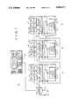
- FIG. 1is a circuit block diagram of three video cassette recorders having a common control system
- FIG. 2is a schematic diagram for illustrating control of two video cassette recorders in an editing operation in the control of a single keyboard, in accordance with the invention.
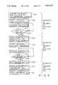
- FIG. 3is a flow diagram illustrating the method of the invention as applied to the editing process illustrated with reference to FIG. 2.
- Each of the video cassette recorders 1, 2 and 3consists of a tape handling unit 1', 2', 3' and a video-audio processor and diagnostic test unit 1", 2", 3" related thereto hereinafter referred to simply as a "processor".
- the three digital video cassette recordersare connected with each other over a serial digital signal bus system 5.
- a coaxial cableconnects the individual handling units and processor units of the digital video cassette recorders 1, 2 and 3.
- Within the tape handling units 1', 2', 3' and the processor units 1", 2", 3"there are a number of coupling elements 6, 7, 8, 9 and 10 for connection with the bus 5.
- the coupling elements 6' to 9'are inserted into the coaxial cable of the bus system 5 within the tape handling unit 1' and the coupling element 10' likewise within the processor unit 1" .
- the coupling elements 6" to 10" and 6"' to 10"'are inserted in the coaxial cable.
- the coupling elements 6-10serve for connecting with computer controlled sending and receiving units further mentioned below.
- Sending and receiving units 11', 12', 13' and 14' which serve for sending and data telegramsare connected respectively to the coupling units 6', 7', 9' and 10'.
- Coupling unit 8'indicates that an additional sending and receiving unit might well be used in a video recording unit.
- the format of the data telegramscan for example correspond to the IEEE-802.3 Standard, whereby the following is prescribed: 8 bytes for a preamble, 6 bytes each for destination and source addresses, 2 bytes for the length, 46-1518 bytes for the actual data information and 4 bytes for a cyclic protective redundance block.
- the transmision rate of the data telegramscan for example be 10 Mbytes per second.
- the method of the present inventioncombines several major apparatus units systematically into a control group (cluster) so that all functions of the individual apparatus units are accessible as further described below. Within that group it is not necessary for the addresses and the telegrams to conform with the IEEE-802.3 standard.
- the coaxial cable of the bus system 5is also connected to an adaptor unit 15 provided for connection to the central operation desk 16.
- This adaptor 15contains, in addition to a coupling element 20 serving the operation desk 16, also an input 21 for supplying operating voltage for the operation control desk.
- Terminating resistor networks 31 and 32are provided at the ends of the bus system 5.
- control unit 16Individual participating major units of the control group according to the invention can also be allocated to the control unit 16 by dynamic address change. With this feature of the invention the single control unit 16 can be allocated to an equipment cluster 4 combining a considerable number of apparatus units.
- the control unit 16can be equipped to control editing operations using two professional video cassette recorder machines, for example. This is illustrated in FIGS. 2 and 3.
- FIG. 2shows only the two recorder machines used in the example, in order to simplify the drawing, and the audio-video processor (and test) units of the recorders shown in FIG. 1 are not shown in FIG. 2 to simplify the drawing.
- FIG. 2shows the video connections between the recorders and with a monitor at the control desk, which are details that were omitted in FIG. 1 to simplify the drawing.
- the monitorcould be built into the control unit 16, but in FIG. 2 it is shown as a separate unit at the control desk.
- the keyboard 116corresponds to the control unit 16 of FIG. 1 and is coupled with the rest of the system shown by the serial data bus 105, which corresponds to the bus 5 of FIG. 1, through the coupler 120, which corresponds to the coupler 20 of FIG. 1, within the adapter 115, which corresponds to the adapter 15 of FIG. 1.
- the bus 105can be referred in the present context to as an internal machine communication system (IMCS) bus.
- IMCSinternal machine communication system
- the bus 105is coupled with the professional type video cassette recorder 101, hereinafter also referred to as machine #1, by the couplers 106, 107 and 109, corresponding to the couplers 6, 7 and 9 of FIG. 1 which are respectively connected to the gateway unit 111, the central processing unit (CPU) 112 and the time-code generator (TG) 113.
- the other connections of the video cassette recorder 101 to the bus 105 which correspond to other couplers shown in FIG. 1are not shown in FIG. 2, in order to simplify the drawing.
- the second professional type video cassette recorder 201similarly has units 211, 212 and 213 shown coupled to the bus 105 respectively through couplers 206, 207 and 209.
- a video monitor 130is provided which is controlled over the bus 105 through a coupler 140.
- the bus 105has a terminating network 131, 132 at each end, in each case symbolized by a resistance connected to ground.
- the video cassette recorders 101 and 201respectively have video inputs 150 and 250 and likewise video outputs 155 and 255. If more than two machines are present in the cluster, as for example in the case of FIG. 1, it would be necessary for each machine to have a plurality of video inputs, in order to make the respective video outputs of other video cassette recorders available for selection, as the active input, by each machine under control of the bus 105.
- the video outputs 155 and 255are connected not only with the video inputs 250 and 150, respectively, but they are also respectively connected to the video inputs 135 and 136 of the video monitor 130. There again, if there were more video cassette recorders in the cluster, additional video inputs would be made available at the monitor.
- the recorders 101 and 201 of the clustermay be physically coupled to other equipment through their respective gateway units 111 and 211, but such other equipment outside the cluster cannot be controlled by the keyboard 116 with the convenience and versatility with which the equipment within the cluster is controlled over the bus 105.
- the destination addresses for the equipment outside of the cluster(coupled through the gateway units in the cluster are not defined in the way that the addresses of the equipments in the cluster) are defined.
- FIG. 2has some dotted lines interconnecting the keyboard 116 with the video cassette recorder 101 and 201, three of them at the left going between the keyboard 116 and the recorder 101 and the three at the right going between the keyboard 116 and the recorder 201. These dotted lines do not represent additional connections but they represent interactions of the keyboard and either the recorder 101 or the recorder 201 which are described in FIG. 3, where recorder 101 is referred to as machine #1 and recorder 201 is referred to as machine #2.
- FIG. 3shows how an editing operation can be performed in accordance with the invention by so-called dynamic addressing by which the keyboard 116 can function as the keyboard exclusively for machine #1 and as the keyboard exclusively for machine #2, in alternation.
- the first stepis to assign the keyboard to machine #1, which is done by setting a return address, by which only machine #1 can reach it for initiating or maintaining interaction, for example the address 8.
- Each message framecontains a destination address and a source addresses.
- the "source address "0 that is transmitted to machine #1will then be the address 8, which will be recognized by machine #1 as the keyboard 16, which thereafter operates as the keyboard control serving exclusively for machine #1. This address 8 is so recognized only by machine #1.
- the next step, shown at 402 in FIG. 3is to start machine #1 in playback. This is identified as command [1] in FIG. 2.
- the next step 403is to monitor the position of the record, command [2], which results in time code data from the unit 113 of machine #1 being displayed on the data display of the keyboard 116 and perhaps also in video output from line 301 being displayed on the video monitor 130 (which would involve a command to the monitor not shown in FIG. 2).
- the next step 404is a decision relating to the tape position data in machine #1.
- the edit pointsmay have been previously determined in terms of time code or by information which was added to the record in a previous running through of the record being played back.
- the video monitoris mainly for showing the operation that a signal is really being recorded: it is too crude to determine the edit point exactly. So long as the edit point is not reached, the return signal from stage 404 ("no") continues the monitoring action specified by stage 403. As soon as the desired position is reached the operation proceeds to stage 405 in which the keyboard is assigned to machine #2 with setting of the appropriate address, now address 9 for access by machine #2 to the keyboard unit 116 and its data display. As in stage 401, that is done simply by the initial message from the keyboard to the selected machine. This address 9 recognized only by machine #2 as the new address of the keyboard 16. Thus any transmissions from machine #1, which is still running, will not be able to reach the keyboard.
- Stage 406starting of machine #2 in recording operation (command [3] in FIG. 2) then takes place immediately. That is followed by a second monitoring stage 407 and a second decision stage 408.
- the second decision stagedepends on information from machine #2, for example time codes from unit 213.
- the keyboardis still assigned to machine #2 and it accordingly then stops machine #2 in stage 409 (command [5] in FIG. 2), followed by stage 410 in which the keyboard is reassigned for machine #1 with setting of appropriate return address (again 8), as before in stage 410.
- machine #1is stopped in state 411, which completes the operation shown in FIG. 3.
- the stored return addressesshould be erased so as to prevent interference with future operations using the same set of return addresses for a different set of equipments which might contain some equipments of a previously used set.
- the keyboard and data display unit 116can be made inaccessible for interaction in either direction by all but one other equipment in the cluster.
- All of the addresses usable by the control unit as a return addressshould have a common feature by which they can be recognized as referring to the control unit.
- the featurewas that they were greater than 7 in an appropriate binary code. It could be that a certain bit place is 1 or 0. It could be an artificial feature: for example the feature that a circuit in the equipment in the control unit designed to respond to any of the predetermined digital addresses will produce a certain prescribed response.
- the common feature of addresses assigned by the control unit as one of its return addresseswill be that the address in question is the source address of a message received by an equipment other than the control unit.
- variable return addressfor a control unit, or its extension to variable addresses for equipment units of a cluster, involves a situation which is normally intolerable within an electronic data processing system.
- conventional data processing systemsit cannot be accepted that the keyboard and display unit at a control desk could by a change of address prevent mutual access between it and all but one (or all but a few) of many equipments of a working group each having a central processing unit (CPU).
- CPUcentral processing unit
Landscapes
- Engineering & Computer Science (AREA)
- Multimedia (AREA)
- Signal Processing (AREA)
- Small-Scale Networks (AREA)
- Management Or Editing Of Information On Record Carriers (AREA)
Abstract
Description
Claims (5)
Applications Claiming Priority (2)
| Application Number | Priority Date | Filing Date | Title |
|---|---|---|---|
| DE3809129 | 1988-03-18 | ||
| DE3809129ADE3809129C2 (en) | 1988-03-18 | 1988-03-18 | Method and device for controlling video-technical devices |
Related Parent Applications (1)
| Application Number | Title | Priority Date | Filing Date |
|---|---|---|---|
| US07316231Continuation-In-Part | 1989-02-27 |
Publications (1)
| Publication Number | Publication Date |
|---|---|
| US5001473Atrue US5001473A (en) | 1991-03-19 |
Family
ID=6350099
Family Applications (1)
| Application Number | Title | Priority Date | Filing Date |
|---|---|---|---|
| US07/517,500Expired - Fee RelatedUS5001473A (en) | 1988-03-18 | 1990-04-30 | Method of controlling a multiplicity of units of video apparatus |
Country Status (2)
| Country | Link |
|---|---|
| US (1) | US5001473A (en) |
| DE (1) | DE3809129C2 (en) |
Cited By (28)
| Publication number | Priority date | Publication date | Assignee | Title |
|---|---|---|---|---|
| US5282038A (en)* | 1990-09-20 | 1994-01-25 | Avs Broadcast, Inc. | Video signal processing system architecture |
| US5305355A (en)* | 1991-04-26 | 1994-04-19 | Pioneer Electronic Corporation | System for data communication on automobile |
| US5475377A (en)* | 1991-10-31 | 1995-12-12 | Lee; Kwang-Sil | Electronic identification system having remote automatic response capability and automatic identification method thereof |
| US5748253A (en)* | 1995-10-12 | 1998-05-05 | Asc Audio Video Corporation | Direct keyboard access to video editing source material |
| US5760698A (en)* | 1994-08-02 | 1998-06-02 | Sony Corporation | Method of selecting an input apparatus |
| US5825411A (en)* | 1996-08-26 | 1998-10-20 | Ultrak, Inc. | Video signal routing system |
| US5870139A (en)* | 1995-08-28 | 1999-02-09 | Ultrak, Inc. | Method and system for video multiplexing |
| US5903308A (en)* | 1996-08-26 | 1999-05-11 | Ultrak, Inc. | Phase compensation for video cameras |
| US5942983A (en)* | 1995-12-07 | 1999-08-24 | Sony Corporation | Assuring data read/write operation in an electronic appliance |
| US5995140A (en)* | 1995-08-28 | 1999-11-30 | Ultrak, Inc. | System and method for synchronization of multiple video cameras |
| US6008867A (en)* | 1996-08-26 | 1999-12-28 | Ultrak, Inc. | Apparatus for control of multiplexed video system |
| US6025874A (en)* | 1995-07-11 | 2000-02-15 | Ultrak, Inc. | Video multiplexer |
| US20020031756A1 (en)* | 2000-04-12 | 2002-03-14 | Alex Holtz | Interactive tutorial method, system, and computer program product for real time media production |
| US20020044764A1 (en)* | 1997-10-22 | 2002-04-18 | Chiyo Akamatsu | Method of using AV devices and AV device system |
| US20020053078A1 (en)* | 2000-01-14 | 2002-05-02 | Alex Holtz | Method, system and computer program product for producing and distributing enhanced media downstreams |
| US20020109710A1 (en)* | 1998-12-18 | 2002-08-15 | Parkervision, Inc. | Real time video production system and method |
| US20020141732A1 (en)* | 2001-03-28 | 2002-10-03 | Koninklijke Philips Electronics N.V. | Multi video device control and expansion method and apparatus |
| US20030001880A1 (en)* | 2001-04-18 | 2003-01-02 | Parkervision, Inc. | Method, system, and computer program product for producing and distributing enhanced media |
| US20030070167A1 (en)* | 2001-04-18 | 2003-04-10 | Alex Holtz | Advertisement management method, system, and computer program product |
| US20030214605A1 (en)* | 1998-12-18 | 2003-11-20 | Snyder Robert J. | Autokeying method, system, and computer program product |
| US20040008220A1 (en)* | 1998-12-18 | 2004-01-15 | Parkervision, Inc. | Director interface for production automation control |
| US20040027368A1 (en)* | 2002-05-09 | 2004-02-12 | Parkervision, Inc. | Time sheet for real time video production system and method |
| US20040070690A1 (en)* | 1998-12-18 | 2004-04-15 | Alex Holtz | Systems, methods, and computer program products for automated real-time execution of live inserts of repurposed stored content distribution, and multiple aspect ratio automated simulcast production |
| US6747706B1 (en)* | 2000-01-11 | 2004-06-08 | International Business Machines Corporation | Workflow process for managing digital broadcast program production |
| US6829783B1 (en)* | 1996-06-28 | 2004-12-07 | Thomson Licensing, S.A. | Arrangement for producing television contributions |
| US6952221B1 (en) | 1998-12-18 | 2005-10-04 | Thomson Licensing S.A. | System and method for real time video production and distribution |
| US7024677B1 (en) | 1998-12-18 | 2006-04-04 | Thomson Licensing | System and method for real time video production and multicasting |
| US8560951B1 (en) | 1998-12-18 | 2013-10-15 | Thomson Licensing | System and method for real time video production and distribution |
Families Citing this family (1)
| Publication number | Priority date | Publication date | Assignee | Title |
|---|---|---|---|---|
| DE19941742A1 (en)* | 1999-09-02 | 2001-03-08 | Vitronic Dr Ing Stein Bildvera | Circuit for generating image data for a PC and corresponding method for data transfer |
Citations (5)
| Publication number | Priority date | Publication date | Assignee | Title |
|---|---|---|---|---|
| US4581645A (en)* | 1983-06-28 | 1986-04-08 | Rca Corporation | Distributed switched component audio/video system |
| US4686698A (en)* | 1985-04-08 | 1987-08-11 | Datapoint Corporation | Workstation for interfacing with a video conferencing network |
| US4689683A (en)* | 1986-03-18 | 1987-08-25 | Edward Efron | Computerized studio for motion picture film and television production |
| US4706081A (en)* | 1984-12-14 | 1987-11-10 | Vitalink Communications Corporation | Method and apparatus for bridging local area networks |
| US4808992A (en)* | 1987-05-08 | 1989-02-28 | Rca Licensing Corporation | Component audio/video system with automatic turn-off of peripheral devices |
- 1988
- 1988-03-18DEDE3809129Apatent/DE3809129C2/ennot_activeExpired - Lifetime
- 1990
- 1990-04-30USUS07/517,500patent/US5001473A/ennot_activeExpired - Fee Related
Patent Citations (6)
| Publication number | Priority date | Publication date | Assignee | Title |
|---|---|---|---|---|
| US4581645A (en)* | 1983-06-28 | 1986-04-08 | Rca Corporation | Distributed switched component audio/video system |
| US4706081A (en)* | 1984-12-14 | 1987-11-10 | Vitalink Communications Corporation | Method and apparatus for bridging local area networks |
| US4686698A (en)* | 1985-04-08 | 1987-08-11 | Datapoint Corporation | Workstation for interfacing with a video conferencing network |
| US4689683A (en)* | 1986-03-18 | 1987-08-25 | Edward Efron | Computerized studio for motion picture film and television production |
| US4689683B1 (en)* | 1986-03-18 | 1996-02-27 | Edward Efron | Computerized studio for motion picture film and television production |
| US4808992A (en)* | 1987-05-08 | 1989-02-28 | Rca Licensing Corporation | Component audio/video system with automatic turn-off of peripheral devices |
Non-Patent Citations (8)
| Title |
|---|
| Anon, "Television Network Automated by Minicomputer-Controlled Channels", Computer Design, vol. 15, No. 11, Nov. 1976, pp. 50, 59, 62, 66, 70. |
| Anon, Television Network Automated by Minicomputer Controlled Channels , Computer Design, vol. 15, No. 11, Nov. 1976, pp. 50, 59, 62, 66, 70.* |
| ANSI/IEEE Std 802.3, Carrier Sense Multiple Access, with Collision Detection, 1985, pp. 13 14, 24 31.* |
| ANSI/IEEE Std 802.3, Carrier Sense Multiple Access, with Collision Detection, 1985, pp. 13-14, 24-31. |
| Cosgrove, "The LDM600 Machine Control System", International Broadcast Engineer, vol. 12, No. 176, pp. 50-55, Mar. 1981. |
| Cosgrove, The LDM600 Machine Control System , International Broadcast Engineer, vol. 12, No. 176, pp. 50 55, Mar. 1981.* |
| Modulares Paralleles Studio Interface Technische Mitteilungen des RFZ , Heft 3/1985, pp. 49 54.* |
| Modulares Paralleles Studio-Interface--"Technische Mitteilungen des RFZ", Heft 3/1985, pp. 49-54. |
Cited By (45)
| Publication number | Priority date | Publication date | Assignee | Title |
|---|---|---|---|---|
| US5282038A (en)* | 1990-09-20 | 1994-01-25 | Avs Broadcast, Inc. | Video signal processing system architecture |
| US5305355A (en)* | 1991-04-26 | 1994-04-19 | Pioneer Electronic Corporation | System for data communication on automobile |
| US5475377A (en)* | 1991-10-31 | 1995-12-12 | Lee; Kwang-Sil | Electronic identification system having remote automatic response capability and automatic identification method thereof |
| US5565857A (en)* | 1991-10-31 | 1996-10-15 | Lee; Kwang-Sil | Electronic indentification system having remote automatic response capability and automatic identification method thereof |
| US5760698A (en)* | 1994-08-02 | 1998-06-02 | Sony Corporation | Method of selecting an input apparatus |
| US6025874A (en)* | 1995-07-11 | 2000-02-15 | Ultrak, Inc. | Video multiplexer |
| US5995140A (en)* | 1995-08-28 | 1999-11-30 | Ultrak, Inc. | System and method for synchronization of multiple video cameras |
| US5870139A (en)* | 1995-08-28 | 1999-02-09 | Ultrak, Inc. | Method and system for video multiplexing |
| US5748253A (en)* | 1995-10-12 | 1998-05-05 | Asc Audio Video Corporation | Direct keyboard access to video editing source material |
| US5942983A (en)* | 1995-12-07 | 1999-08-24 | Sony Corporation | Assuring data read/write operation in an electronic appliance |
| US6829783B1 (en)* | 1996-06-28 | 2004-12-07 | Thomson Licensing, S.A. | Arrangement for producing television contributions |
| US5903308A (en)* | 1996-08-26 | 1999-05-11 | Ultrak, Inc. | Phase compensation for video cameras |
| US6008867A (en)* | 1996-08-26 | 1999-12-28 | Ultrak, Inc. | Apparatus for control of multiplexed video system |
| US5825411A (en)* | 1996-08-26 | 1998-10-20 | Ultrak, Inc. | Video signal routing system |
| US20020044764A1 (en)* | 1997-10-22 | 2002-04-18 | Chiyo Akamatsu | Method of using AV devices and AV device system |
| US7224886B2 (en)* | 1997-10-22 | 2007-05-29 | Hitachi, Ltd. | Method of using AV devices and AV device system |
| US7302644B2 (en) | 1998-12-18 | 2007-11-27 | Thomson Licensing | Real time production system and method |
| US7024677B1 (en) | 1998-12-18 | 2006-04-04 | Thomson Licensing | System and method for real time video production and multicasting |
| US10056111B2 (en) | 1998-12-18 | 2018-08-21 | Gvbb Holdings S.A.R.L. | Systems, methods, and computer program products for multiple aspect ratio automated simulcast production |
| US20020175931A1 (en)* | 1998-12-18 | 2002-11-28 | Alex Holtz | Playlist for real time video production |
| US20020186233A1 (en)* | 1998-12-18 | 2002-12-12 | Alex Holtz | Real time video production system and method |
| US9711180B2 (en) | 1998-12-18 | 2017-07-18 | Gvbb Holdings S.A.R.L. | Systems, methods, and computer program products for automated real-time execution of live inserts of repurposed stored content distribution |
| US9558786B2 (en) | 1998-12-18 | 2017-01-31 | Gvbb Holdings S.A.R.L. | Systems, methods, and computer program products for multiple aspect ratio automated simulcast production |
| US20030214605A1 (en)* | 1998-12-18 | 2003-11-20 | Snyder Robert J. | Autokeying method, system, and computer program product |
| US20040008220A1 (en)* | 1998-12-18 | 2004-01-15 | Parkervision, Inc. | Director interface for production automation control |
| US9123380B2 (en) | 1998-12-18 | 2015-09-01 | Gvbb Holdings S.A.R.L. | Systems, methods, and computer program products for automated real-time execution of live inserts of repurposed stored content distribution, and multiple aspect ratio automated simulcast production |
| US20040070690A1 (en)* | 1998-12-18 | 2004-04-15 | Alex Holtz | Systems, methods, and computer program products for automated real-time execution of live inserts of repurposed stored content distribution, and multiple aspect ratio automated simulcast production |
| US8560951B1 (en) | 1998-12-18 | 2013-10-15 | Thomson Licensing | System and method for real time video production and distribution |
| US20020109710A1 (en)* | 1998-12-18 | 2002-08-15 | Parkervision, Inc. | Real time video production system and method |
| US8006184B2 (en) | 1998-12-18 | 2011-08-23 | Thomson Licensing | Playlist for real time video production |
| US6952221B1 (en) | 1998-12-18 | 2005-10-04 | Thomson Licensing S.A. | System and method for real time video production and distribution |
| US6452612B1 (en) | 1998-12-18 | 2002-09-17 | Parkervision, Inc. | Real time video production system and method |
| US7835920B2 (en) | 1998-12-18 | 2010-11-16 | Thomson Licensing | Director interface for production automation control |
| US6747706B1 (en)* | 2000-01-11 | 2004-06-08 | International Business Machines Corporation | Workflow process for managing digital broadcast program production |
| US20020053078A1 (en)* | 2000-01-14 | 2002-05-02 | Alex Holtz | Method, system and computer program product for producing and distributing enhanced media downstreams |
| US20020031756A1 (en)* | 2000-04-12 | 2002-03-14 | Alex Holtz | Interactive tutorial method, system, and computer program product for real time media production |
| US6909874B2 (en) | 2000-04-12 | 2005-06-21 | Thomson Licensing Sa. | Interactive tutorial method, system, and computer program product for real time media production |
| US7881585B2 (en) | 2001-03-28 | 2011-02-01 | Robert Bosch Gmbh | Multi video device control and expansion method and apparatus |
| US20020141732A1 (en)* | 2001-03-28 | 2002-10-03 | Koninklijke Philips Electronics N.V. | Multi video device control and expansion method and apparatus |
| US20030070167A1 (en)* | 2001-04-18 | 2003-04-10 | Alex Holtz | Advertisement management method, system, and computer program product |
| US20030001880A1 (en)* | 2001-04-18 | 2003-01-02 | Parkervision, Inc. | Method, system, and computer program product for producing and distributing enhanced media |
| US11109114B2 (en) | 2001-04-18 | 2021-08-31 | Grass Valley Canada | Advertisement management method, system, and computer program product |
| US20040027368A1 (en)* | 2002-05-09 | 2004-02-12 | Parkervision, Inc. | Time sheet for real time video production system and method |
| US10360944B2 (en) | 2002-05-09 | 2019-07-23 | Gvbb Holdings S.A.R.L. | Systems, methods, and computer program products for multiple aspect ratio automated simulcast production |
| US10546612B2 (en) | 2002-05-09 | 2020-01-28 | Gvbb Holdings S.A.R.L. | Systems, methods, and computer program products for automated real-time execution of live inserts of repurposed stored content distribution |
Also Published As
| Publication number | Publication date |
|---|---|
| DE3809129A1 (en) | 1989-10-05 |
| DE3809129C2 (en) | 1994-06-09 |
Similar Documents
| Publication | Publication Date | Title |
|---|---|---|
| US5001473A (en) | Method of controlling a multiplicity of units of video apparatus | |
| US5809246A (en) | Selection and retrieval of music from a digital database | |
| US6021308A (en) | On-vehicle data communication system and method | |
| EP1003166B1 (en) | Information data recording/reproducing apparatus and information data processing system | |
| EP0467305B1 (en) | Apparatus for connecting electronic appliances | |
| US5760698A (en) | Method of selecting an input apparatus | |
| US5621659A (en) | Central control device and operation devices | |
| US5539390A (en) | Method for setting addresses for series-connectd apparatuses | |
| US5959539A (en) | Apparatus for the remote control of electronic devices with key allocation | |
| US5563886A (en) | Address assignment and control of a single connection terminal device on a bus | |
| JP3077467B2 (en) | Electronic device, transmission signal reception method, and transmission signal transmission method | |
| US5940398A (en) | Method for common transmission of digital source and control data between data sources and data sinks connected through data lines | |
| US4628442A (en) | Centralized peripheral interface with a numerical control unit | |
| EP0482953B1 (en) | Method of and system for data communication in communication network on automobile | |
| EP0482959A2 (en) | System for data communication | |
| EP0127967A1 (en) | Remote control systems | |
| CN1065385C (en) | Method of controlling signal lines among audio and/or video apparatus | |
| US5157508A (en) | Television signal equipment assignment matrix including passive switching | |
| JPH09130716A (en) | Av system modularized by function | |
| EP0482958A2 (en) | System for data communication | |
| JP3190709B2 (en) | Electronics | |
| US5502436A (en) | Method of identifying a signal path and signal processing apparatus | |
| JPH0241505A (en) | Remote monitoring and control device for NG equipment | |
| JPH0771066B2 (en) | Data transmission equipment | |
| JPH08102983A (en) | Control method for audio visual system |
Legal Events
| Date | Code | Title | Description |
|---|---|---|---|
| AS | Assignment | Owner name:BTS BROADCAST TELEVISION SYSTEMS GMBH, D-6100 DARM Free format text:ASSIGNMENT OF ASSIGNORS INTEREST.;ASSIGNORS:RITTER, UWE;STURM, RAINER;REEL/FRAME:005439/0640 Effective date:19900608 | |
| FEPP | Fee payment procedure | Free format text:PAYOR NUMBER ASSIGNED (ORIGINAL EVENT CODE: ASPN); ENTITY STATUS OF PATENT OWNER: LARGE ENTITY | |
| FPAY | Fee payment | Year of fee payment:4 | |
| FPAY | Fee payment | Year of fee payment:8 | |
| AS | Assignment | Owner name:BTS HOLDING INTERNATIONAL B.V., NETHERLANDS Free format text:ASSIGNMENT OF ASSIGNORS INTEREST;ASSIGNOR:PHILIPS GMBH;REEL/FRAME:013280/0293 Effective date:20020704 | |
| REMI | Maintenance fee reminder mailed | ||
| LAPS | Lapse for failure to pay maintenance fees | ||
| AS | Assignment | Owner name:PHILIPS BROADCAST TELEVISION SYSTEMS GMBH, GERMANY Free format text:A CHANGE IN CORPORATE NAME FROM "BTS BROADCAST TELEVISION SYSTEMS GMBH" TO --PHILIPS BROADCAST TELEVISION SYSTEMS GMBH;ASSIGNOR:BTS BROADCAST TELEVISION SYSTEMS GMBH;REEL/FRAME:013897/0301 Effective date:20020704 Owner name:PHILIPS GMBH, GERMANY Free format text:MERGER;ASSIGNOR:PHILIPS BROADCAST TELEVISION SYSTEMS GMBH;REEL/FRAME:013907/0025 Effective date:20020704 | |
| STCH | Information on status: patent discontinuation | Free format text:PATENT EXPIRED DUE TO NONPAYMENT OF MAINTENANCE FEES UNDER 37 CFR 1.362 | |
| FP | Lapsed due to failure to pay maintenance fee | Effective date:20030319 |