US5000442A - Cross country ski exerciser - Google Patents
Cross country ski exerciserDownload PDFInfo
- Publication number
- US5000442A US5000442AUS07/481,169US48116990AUS5000442AUS 5000442 AUS5000442 AUS 5000442AUS 48116990 AUS48116990 AUS 48116990AUS 5000442 AUS5000442 AUS 5000442A
- Authority
- US
- United States
- Prior art keywords
- track
- trolley
- exercise machine
- main member
- guide
- Prior art date
- Legal status (The legal status is an assumption and is not a legal conclusion. Google has not performed a legal analysis and makes no representation as to the accuracy of the status listed.)
- Expired - Lifetime
Links
Images


Classifications
- A—HUMAN NECESSITIES
- A63—SPORTS; GAMES; AMUSEMENTS
- A63B—APPARATUS FOR PHYSICAL TRAINING, GYMNASTICS, SWIMMING, CLIMBING, OR FENCING; BALL GAMES; TRAINING EQUIPMENT
- A63B69/00—Training appliances or apparatus for special sports
- A63B69/18—Training appliances or apparatus for special sports for skiing
- A63B69/182—Training appliances or apparatus for special sports for skiing for cross-country-skiing
- A—HUMAN NECESSITIES
- A63—SPORTS; GAMES; AMUSEMENTS
- A63B—APPARATUS FOR PHYSICAL TRAINING, GYMNASTICS, SWIMMING, CLIMBING, OR FENCING; BALL GAMES; TRAINING EQUIPMENT
- A63B21/00—Exercising apparatus for developing or strengthening the muscles or joints of the body by working against a counterforce, with or without measuring devices
- A63B21/00058—Mechanical means for varying the resistance
- A63B21/00069—Setting or adjusting the resistance level; Compensating for a preload prior to use, e.g. changing length of resistance or adjusting a valve
- A—HUMAN NECESSITIES
- A63—SPORTS; GAMES; AMUSEMENTS
- A63B—APPARATUS FOR PHYSICAL TRAINING, GYMNASTICS, SWIMMING, CLIMBING, OR FENCING; BALL GAMES; TRAINING EQUIPMENT
- A63B21/00—Exercising apparatus for developing or strengthening the muscles or joints of the body by working against a counterforce, with or without measuring devices
- A63B21/012—Exercising apparatus for developing or strengthening the muscles or joints of the body by working against a counterforce, with or without measuring devices using frictional force-resisters
- A63B21/018—Exercising apparatus for developing or strengthening the muscles or joints of the body by working against a counterforce, with or without measuring devices using frictional force-resisters including a rope or other flexible element moving relative to the surface of elements
- A—HUMAN NECESSITIES
- A63—SPORTS; GAMES; AMUSEMENTS
- A63B—APPARATUS FOR PHYSICAL TRAINING, GYMNASTICS, SWIMMING, CLIMBING, OR FENCING; BALL GAMES; TRAINING EQUIPMENT
- A63B22/00—Exercising apparatus specially adapted for conditioning the cardio-vascular system, for training agility or co-ordination of movements
- A63B22/0002—Exercising apparatus specially adapted for conditioning the cardio-vascular system, for training agility or co-ordination of movements involving an exercising of arms
- A63B22/001—Exercising apparatus specially adapted for conditioning the cardio-vascular system, for training agility or co-ordination of movements involving an exercising of arms by simultaneously exercising arms and legs, e.g. diagonally in anti-phase
- A63B22/0012—Exercising apparatus specially adapted for conditioning the cardio-vascular system, for training agility or co-ordination of movements involving an exercising of arms by simultaneously exercising arms and legs, e.g. diagonally in anti-phase the exercises for arms and legs being functionally independent
- A—HUMAN NECESSITIES
- A63—SPORTS; GAMES; AMUSEMENTS
- A63B—APPARATUS FOR PHYSICAL TRAINING, GYMNASTICS, SWIMMING, CLIMBING, OR FENCING; BALL GAMES; TRAINING EQUIPMENT
- A63B22/00—Exercising apparatus specially adapted for conditioning the cardio-vascular system, for training agility or co-ordination of movements
- A63B22/20—Exercising apparatus specially adapted for conditioning the cardio-vascular system, for training agility or co-ordination of movements using rollers, wheels, castors or the like, e.g. gliding means, to be moved over the floor or other surface, e.g. guide tracks, during exercising
- A63B22/201—Exercising apparatus specially adapted for conditioning the cardio-vascular system, for training agility or co-ordination of movements using rollers, wheels, castors or the like, e.g. gliding means, to be moved over the floor or other surface, e.g. guide tracks, during exercising for moving a support element in reciprocating translation, i.e. for sliding back and forth on a guide track
- A63B22/203—Exercising apparatus specially adapted for conditioning the cardio-vascular system, for training agility or co-ordination of movements using rollers, wheels, castors or the like, e.g. gliding means, to be moved over the floor or other surface, e.g. guide tracks, during exercising for moving a support element in reciprocating translation, i.e. for sliding back and forth on a guide track in a horizontal plane
- A—HUMAN NECESSITIES
- A63—SPORTS; GAMES; AMUSEMENTS
- A63B—APPARATUS FOR PHYSICAL TRAINING, GYMNASTICS, SWIMMING, CLIMBING, OR FENCING; BALL GAMES; TRAINING EQUIPMENT
- A63B22/00—Exercising apparatus specially adapted for conditioning the cardio-vascular system, for training agility or co-ordination of movements
- A63B22/0025—Particular aspects relating to the orientation of movement paths of the limbs relative to the body; Relative relationship between the movements of the limbs
- A63B2022/0041—Particular aspects relating to the orientation of movement paths of the limbs relative to the body; Relative relationship between the movements of the limbs one hand moving independently from the other hand, i.e. there is no link between the movements of the hands
- A—HUMAN NECESSITIES
- A63—SPORTS; GAMES; AMUSEMENTS
- A63B—APPARATUS FOR PHYSICAL TRAINING, GYMNASTICS, SWIMMING, CLIMBING, OR FENCING; BALL GAMES; TRAINING EQUIPMENT
- A63B2210/00—Space saving
- A63B2210/50—Size reducing arrangements for stowing or transport
Definitions
- This applicationrelates to exercise machines and more particularly to the type of exercise machines which are used to perform cross country skiing type exercises.
- Cross country skiing exercise machinestypically involve two spaced-apart tracks with two ski pedals positioned thereon.
- the pedalsare typically, but not necessarily secured to each other to reciprocate relative to each other. That is, as one pedal moves forward on its track, the pedal on the adjacent track moves rearwardly.
- Some cross country ski exercise machinesalso include levers which are operable by the user in a to-and-fro or forward and rearward direction to simulate the use of ski poles in association with actual cross country skiing.
- the leversare typically positioned for operation by each hand of the user standing on the ski pedals.
- cross country skiing machinesinclude cables interconnected between the ski pedal and the corresponding lever to provide for coordinated movement between the pedal and the lever.
- Cross country ski exercise machinesare also known to have an upright member extending from the forward end of the machine rearwardly to a height proximate an adult user's abdomen with an extension member extending away therefrom about which interconnecting cables between the respective pedals and lever arms are trained.
- Such machinesare difficult to store because the upright main member and the extension member of existing or known machines interferes with easy storage or compact storage absent substantial disassembly. Further, such machines may require substantial assembly when purchased.
- cross country ski exercise machineshave structure to resist movement of the ski pedals in a back and forth motion.
- U.S. Pat. No. 4,813,667illustrates a machine with cross country capability in which variable resistance may be imposed to resist the movement of the respective pedals operated by the upright user.
- a simplified and effective resistance systemis desirable for a cross country ski machine which is substantially preassembled and easily placed in a storage condition which is compact and easily restored to an operating configuration from the storage condition.
- An exercise machinehas a first and second track each having forward and rearward end.
- the first trackis spaced from the second track a preselected distance and in substantial alignment.
- the first trolleyis positioned on the first track and the second trolley is positioned on the second track both to move forwardly and rearwardly therealong and to support one foot of an upright user.
- a main memberhas an upper end and a lower end. The lower end is pivotally secured to and between the first and second tracks. The main member is movable between the down position in which it is located proximate the first and second track and an up position in which it extends upwardly from the first and second tracks.
- An extension memberhas an inward and outward end.
- the inward endis pivotally secured to the upper end of the main member.
- the extension memberis movable between an open position in which the extension member extends away from the main member and a closed positioned in which the extension member is positioned proximate the main member.
- First and second lever meansare each pivotally and mechanically associated with the first and second tracks respectively for grasping and movement forwardly and rearwardly by the hands of an upright user.
- Reciprocating meansinterconnect the first and second trolleys to cause each to move relative to the other on their respective first and second tracks.
- First cable meansinterconnects the first lever means and the first trolley to cause the first trolley to move forwardly on the first track upon rearward movement of the first lever.
- second cable meansinterconnects the second lever means with the second trolley to cause the second trolley to move forwardly on the second track upon rearward movement of the second lever.
- the main memberhas a width which is sized less than the preselected distance between the first and second track. In a down position the main member is therefore positioned substantially between the first and second tracks. More preferably, the extension member is in substantial alignment with the main member when the extension member is in the closed position.
- the extension memberhas extension guide means secured at its outward end for guiding the first cable means and the second cable means thereabout. More preferably, the extension member is sized in length to extend forwardly of the first and second trolley means when the first and second trolley means are positioned proximate each other, the main member is positioned in a down position and the extension member is in a closed position.
- the exercise machineincludes resistance means to resist movement of the first trolley and the second trolley.
- the reciprocating meansincludes strap means formed into a continuous loop to which the first and second trolleys are connected.
- the resistance meanspreferably includes a friction means to resist movement of the strap means.
- the friction meansincludes a first post spaced apart from a second post each mounted to a base.
- the strap meansis trained between the first and second posts.
- the baseis rotatable to urge the first post and the second post toward the strap means trained thereinbetween.
- adjustment meansis provided to rotate the base.
- the adjustment meansincludes operation means positioned for operation by an upright user positioned on the first and second trolleys. Connection means interconnect between the operation means and the base to cause the base to rotate upon operation of the operation means to increase or decrease friction imposed on the strap and in turn vary the resistance of the resistance means.
- a first trunnionis secured to the first track at its forward end; and a second trunnion is secured to the second track at its forward end in substantial axial alignment with the first trunnion.
- a shaftis sized to snugly and rotatably extend through the first and second trunnions.
- the first and second lever meansare each pivotally mounted to the shaft.
- the first and second trunnionsare preferably spaced apart.
- the main memberdesirably has a journal at its lower end which is positioned between the first and second trunnions.
- the journalis sized to rotatably receive the shaft therethrough.
- the journalis spaced from the first trunnion and the second trunnion to form the first guide surface and the second guide surface on said shaft.
- the first cable means and the second cable meansare each trained about their respective first guide surface and second guide surface.
- the shafthas a first end and a second end which extend outwardly from the first trunnion and the second trunnion, respectively.
- the first leveris desirably journaled to pivot about the first end and the second lever is journaled to pivot about the second end.
- forward support guide meansare secured proximate the forward end of the first track, and rear guide means are secured proximate the rearward end of said second track.
- the forward support guide and rear guide meansguide the strap means which is trained thereabout.
- support meansinterconnect the first track with the second track.
- the support meansinclude a forward support means and a rear support means.
- the forward guide meansis a pair of spaced apart forward posts positioned transverse to each other and secured to extend downwardly from the forward support means.
- the rear guide meansis a pair of spaced apart rear posts positioned transverse to each other to extend downwardly from the rear support means.
- the pair of forward posts and the pair of rear postsare preferably mounted in a substantial rectilinear pattern.
- Support feet to support the exercise machineare preferably associated with each of the posts to support the machine on an appropriate surface.
- the main memberhas the directional guide means secured proximate its upper end about which the first cable means and the second cable means are trained.
- the main memberincludes securing means to secure the main member in the up position.
- the extension memberalso includes securing means to secure the extension member in the open position.
- the forward support meansis positioned proximate the first and second journal and has a lip extending forwardly and downwardly.
- the journal secured to the downward end of the main memberhas an extension adapted thereto.
- the extensionis preferably secured to the lip to hold the main member in an up position by means operable by the user.
- Such meansmay be an adjustment knob with a threaded screw to interconnect the extension to the lip.
- the lip and the extensionare desirably positioned to orient the main member upwardly and rearwardly in the up position.
- a cushionmay be positioned at the upward end of the main member for contact with the upright user positioned on the first trolley and the second trolley.
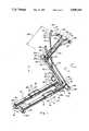
- FIG. 1is a perspective view of an exercise machine of the present invention in a first configuration
- FIG. 2is another perspective view of the invention of FIG. 1 in a first configuration
- FIG. 3is a perspective view of the invention of FIG. 1 in a second configuration
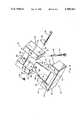
- FIG. 4is an exploded view of the forward end of the exercise machine of FIG. 1;
- FIG. 5is a partial simplified cross-sectional view of the forward end of the exercise machine of FIG. 1;
- FIG. 6is a perspective view of portions of the exercise machine of FIG. 1;
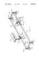
- FIG. 7is a simplified depiction of the reciprocating structure of the exercise machine of FIG. 1;
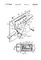
- FIG. 8is a perspective simplified view of the friction structure of the exercise machine of FIG. 1;
- FIG. 9is a cross-sectional view of portions of the resistance structure of the exercise machine of FIG. 1.
- FIG. 1illustrates an exercise machine which is a cross country skiing type exercise machine.
- the depicted machineis generally referred to by the numeral 10. It has a first track 12 having a forward end 14 and rearward end 16. It also has a second track 18 with a forward end 20 and a rearward end 22. As illustrated, the second track 18 is spaced from the first track 12 a preselected distance 24.
- the first track 12 and the second track -8are here shown to be in substantial alignment. Preferably they are essentially parallel.
- a first trolley 26is positioned on the first track 12 to move forwardly 28 and rearwardly 30 therealong and to support one foot of an upright user.
- a second trolley 32is positioned on the second track 18 to move forwardly 34 and rearwardly 36 and to support the other foot of an upright user.
- the machine 10has a main member 38 having an upper end 40 and a lower end 42.
- the lower end 42is pivotally secured to and between the first track 12 and the second track 18 as more fully discussed hereinafter.
- the main member 38is movable between a down position in which the main member is positioned proximate the first and second tracks 12 and 18 as depicted in FIG. 3, and an up position in which the main member 38 extends upwardly from the first and second tracks 12 and 18 as depicted in FIGS. 1 and 2.
- the machine of FIG. 1also has an extension member 44 which has an inward end 46 and an outward end 48.
- the inward endis pivotally secured to the upper end 40 of the main member 38 to move between an open position in which the extension member 44 extends away from the main member 38 and a closed position in which the extension member 44 is positioned proximate the main member 38.
- the extension member 44is oriented normal to the main member 38 which is the preferred open position.
- the main member 44is shown in a preferred closed position.
- the machine 10 of FIG. 1also has first lever means in the form of lever 50 pivotally and mechanically associated with the first track 12 for grasping and movement forwardly 28 and rearwardly 30 by one hand of an upright user.
- a second lever means in the form of 52is pivotally and mechanically associated with the second track 18 for grasping a movement forwardly 34 and rearwardly 36 by one hand of the upright user.
- the machine 10 of FIG. 1also includes reciprocating means which is interconnected between the first trolley 26 and the second trolley 32.
- the reciprocating meansis not shown in FIG. 1, but is discussed and illustrated in more detail hereinafter.
- the reciprocating meanscauses the first trolley 26 and the second trolley 32 to move relative to each other. That is, upon movement of the first trolley 26 forwardly 28, the second trolley 32 moves rearwardly 36. Similarly, when the second trolley 32 moves forwardly 34 the first trolley 26 moves rearwardly.
- the machine 10 of FIG. 1also includes first cable means in the form of cable 54 which interconnects the first lever 50 with the first trolley 26 to cause the trolley 26 to move forwardly 28 upon rearward 30 movement of the first lever 50.
- the machine 10also includes a second cable means in the form of cable 56 interconnected between a second trolley 32 and the second lever 52. The cable 56 causes the second trolley 32 to move forwardly 34 upon rearward 36 movement of the second lever 52.
- the main member 38has a width 58 which is sized to be less than the distance 24 between the first track 12 and the second track 18.
- the distance 24is selected so that the trolleys 26 and 32 are each spaced apart to be comfortable for an adult user. That is, the distance 24 is selected to be comparable to the spacing between the feet of an adult user performing cross country ski exercises.
- the width 58 of the main member 38is selected to be less than distance 24 so the main member 38 can be positioned substantially between the first track 12 and second track 18 when in the down position, as illustrated in FIG. 3.
- a first trunnion 60is secured to the forward end 14 of the first track 12.
- the second trunnion 62is similarly secured to the front end 20 of the second track 18.
- the trunnions 60 and 62are hollow tube-like structures which are sized to receive shaft 64 therethrough. That is, the shaft 64 is sized in diameter 66 to slide through the trunnions 60 and 62 which are positioned to be in axial alignment 68 to receive the shaft 64.
- the shaft 64has a first end 70 and a second end 72.
- first end 70extends outwardly from the first trunnions 60; and the second end 72 extends outwardly from the second trunnion 62.
- the first lever 50is pivotally attached to and secured to pivot about the first end 70 of the shaft 64. It is secured in place with a bushing 74 which inter-fits with a journal 76 connected to the lever 50.
- journal 78is connected to lever 52.
- the journal 78receives a bushing 80 along with an end cap 82. As illustrated in FIG.
- the end cap 82holds the journal 78 to the shaft 64 by use of a spacer 84, a washer 86 and a bolt 88 to interconnect to an interiorly positioned threaded connection 90 in the second end 72 of the shaft 64.
- a similar threaded connectionis positioned inside the first end 70 of the shaft 64 to receive a bolt similar to bolt 88 (not shown) for holding an end cap 92 to the first end 70 of shaft 64.
- a journal 94is secured to the lower end 42 of the main member 38.
- the journalis sized to fit between the trunnions 60 and 62 and to receive the shaft 64 therethrough as illustrated.
- the journal 94has a spacer tab 95 on its first end and a spacer tab 96 on its second end.
- the spacer tabs 95 and 96space the journal 94 from the trunnions 60 and 62.
- the spacerexposes a portion of the shaft 64 which constitutes a first guide surface on the first side of the journal 94 and a second guide surface on the second side of the journal 94.
- the first and second cables 54 and 56are respectively trained about the first and second guide surfaces to interconnect with the first trolley 26 and second trolley 32 respectively, as more fully illustrated in FIG. 1.
- a support meansis provided to secure the first track 12 and the second track 18 together.
- a forward support 100 and a rear support 102are shown in FIG. 1.
- the forward support 100is more clearly shown in FIG. 5 to be positioned proximate the forward end of the machine 10 and more specifically proximate the forward ends 14 and 20 of the first track 12 and the second track 18 respectively.
- the forward support 100has a downwardly extending lip 104.
- the lip 104extends downwardly at an angle 106 which is also the angle (about 30 degrees) at which the main member 38 extends rearwardly when in the up position.
- the journal 94 positioned at the downward end 42 of the main member 38has an extension 108 secured thereto in general alignment with the main member 38.
- the main member 38may rotate downwardly 110 to the down position as illustrated in FIG. 3 or upwardly 112 to the up position as illustrated in FIGS. 1 and 2.
- the extension 108is positioned proximate the lip 104 and is secured thereto by a knob 114 with a threaded bolt 116 sized to extend through aperture 118 and to be received in threaded aperture 120.
- the main member 38is securely positioned at the angle 106 to extend rearwardly toward the upright user on the trolleys 26 and 32 as more fully discussed hereinafter.
- the bracket 122has apertures 124, and 126 formed therein to receive screws to fixedly hold the bracket 122 to the upper end 40 of the main member 38.
- the bracket 122has a tongue 128 extending substantially normal thereto with a downwardly extending right flange 130 and left flange 132 shown in phantom.
- the inward end 46 of the extension member 44has a right member 134 and a left member 136 which are spaced apart and sized to snugly fit about the flanges 130 and 132.
- the inward end 46 of the extension member 44has apertures 138 and 140 formed therein to register with the apertures 142 and 144 formed in the flanges 130 and 132.
- An appropriate bolt 146 with a washer 148 and a bushing 150may be inserted through the apertures 138, 140, 142 and 144 to interconnect with a lock nut 152 to pivotally secure the inward end 46 of the extension member 44 to the upper end 40 of the main member 38.
- the extension member 44has an inter-spacing bracket 154 secured between the spaced apart members 134 and 136.
- the bracket 154has a threaded aperture 156 which is positioned to register with aperture 158 in the tongue 128 when the extension member 44 is positioned in the open position.
- a threaded bolt 160 with an extension bushing 162is used to secure the spacer 154 to the underside 164 of the tongue 128 to hold the extension member 44 in the open position illustrated in FIGS. 1 and 2.
- the ends 66 and 168 of the right member 134 and left member 136 of the extension 44are spaced away from the outward surface 170 of the main member 38 so that upon removal of the bolt 160, the extension member 44 may rotate to the closed position in which the under surface 172 of the extension 44 is substantially parallel to the outward surface 170 of the main member 40 as illustrated in FIG. 3.
- extension member 44 and the main member 38may be secured to place the machine 10 of FIG. 1 in its first configuration as illustrated in FIGS. 1 and 2.
- the machine 10 of FIG. 1can be repositioned into a collapsed or second configuration as illustrated in FIG. 3.
- the extension member 44 and the upright member 38scissor downwardly to a configuration which is compact for shipment and for storage.
- assembly of a machinemay be simplified for the user because the machine 10 may be pre-assembled by the maker so that assembly involves movement of the main member 38 to its up position and insertion of the bolt 116 and operation of the knob 114 along with operation of the extension 44 to its open position and operation of the bolt 160 to secure the extension 44 in the open position.
- the extension memberhas an extension guide 174 secured thereto at the outer end 48.
- the guide 174functions to guide the first and second cables 54 and 56 between the first lever 50 and its respective first trolley 26 and the second lever 52 and its second respective second trolley 32.
- the cable 54is secured to a hand grip 176 positioned on the distal end 178 of the lever 50.
- the cable 54can be connected to the lever 50 and disconnected from the lever 50 by simply attaching or removing the handgrip 176 from the distal end 178 of the lever 50.
- the second lever 52has a hand grip 180 secured at the distal end 182 of the lever 52.
- the cable 56is secured to the handgrip 180 for attachment and removal from the lever 52.
- the cable 54is trained about a first pulley 184 and a second pulley 186.
- the second cable 56is trained about pulleys 188 and 190.
- the cables 54 and 56extend downwardly to a guide structure positioned at the upper end 40 of the main member 38.
- the guide structure illustratedis pulley 192 and 194.
- the cables 54 and 56are thereafter led from pulleys 192 and 194 and trained about the first guide surface and second guide surface of the shaft 64. Thereafter the cables 54 and 56 are led rearwardly for connection to their respective trolleys 26 and 32.
- a safety cap 196is positioned over the pulley 184, 186, 188 and 190 as best illustrated in FIG. 2.
- the configuration of the cables 54 and 56 illustrated in FIG. 1keeps the cables in alignment with the structure of the machine 10 to avoid interfering cable runs and to facilitate pre-assembly. That is, the grips 176 and 180 may be removed from the distal ends 178 and 182 respectively of the first and second levers 50 and 52, respectively. Upon removal, and positioning of the main member 38 and extension member 44 into the collapsed or stored condition as illustrated in FIG. 3, the handgrip 176 (not shown) and handgrip 180 lay proximate the tracks 12 and 18. Similarly, the handles 50 and 52 may be pivoted to be proximate to and in alignment with the tracks 12 and 18.
- the extension 44is sized in length 198 to extend forwardly of the trolleys 26 and 32 when the trolleys are positioned proximate each other as illustrated in FIG. 3 and with the main member 38 in the down position as illustrated in FIG. 3.
- the repositioning of the machine 10 of FIG. 1 between the stored or pre-assembled configuration of FIG. 3 to the assembled and upright configuration of FIG. 1may be effected by raising the main member 38 and positioning the extension member 44 while securing both of them in their positions as hereinbefore discussed.
- the ribs 176 and 180are easily positioned on the distal ends 178 and 182 of the levers 50 and 52. Thereupon, a fully assembled machine 10 is readily available for operation by the user.
- reciprocating meansare provided to cause the first trolley 26 and the second trolley 32 to move relative to each other or to reciprocate on their respective tracks 12 and 18.
- the reciprocating means of the machine in FIG. 1includes a strap 200 formed into a continuous loop as illustrated. More specifically, a loop is formed by taking the first end 202 and assembling it in a buckle-like fashion through a buckle structure 204. Similarly, the other end 206 may be assembled to the buckle 204.
- the first trolley 26may be connected to a drive bracket 208 with an extension 209 which is in turn connected by a bolt 210 to the strap 200.
- the second trolley 32(not shown) is connected by a bracket 212 with an extension to the strap 200 and more particularly to the buckle 204 by belt 215.
- Guidesare positioned under the tracks 12 and 18 to guide the strap 200.
- a forward guide structure and a rear guide structureare provided.
- the forward guide structureincludes a first guide post 214 spaced apart from a second guide post 218.
- the first forward guide post 214is preferably secured to the support 100 proximate the forward end 14 of the first track 12.
- a second forward guide post 218is secured to the support 100 proximate the forward end 20 of the second track 18.
- the rear guide structure as here illustratedincludes a pair of rear posts.
- the first rear post 220is connected to the support 102 proximate the rearward end 16 of the first track 12
- the second rear post 222is secured to the support 102 proximate the rearward end 22 of the second track 18.
- the posts 214, 218, 220, and 222are configured in a rectilinear pattern so that the strap 200 is positioned in a rectilinear pattern with a first stretch 224 positioned under the first track 12 and a second stretch 226 positioned underneath the second track 18.
- forward or rearward movement 228 of the strap 200 and more particularly the first stretch 224causes corresponding rearward and forward movement to 230 of the second stretch 226.
- the strap 200is preferably made out of a low friction nylon mesh or other material which slides easily about the posts 214, 218, 220 and 222 Which are all relatively smooth and cylindrically shaped.
- the strap 200 of FIG. 7has a forward stretch 232 which is associated with resistance means and more particularly a friction means.
- a base 234has a first post 236 extending away therefrom and secured thereto. It also has a second post 238 secured thereto and extending away therefrom. The post 236 and post 238 are spaced apart with the stretch 232 passing therebetween.
- the base 234is secured to the support 100 by a nut 239 and a bolt 240 which passes through aperture 242 in the base 234 and corresponding apertures (not shown) in the support 100 and back base 243. The base 234 may therefore rotate 246 about the bolt 240.
- the pin 236Upon rotation of the base 234, the pin 236 is urged upwardly 248 to press against the strap 200 and more particularly the stretch 232. At the same time, the post 238 rotates downwardly 250 to press against the stretch 232. It can be seen that increasing clockwise 251 rotation of the base 234 also increases the tension of the stretch 232 and in turn the resistance between the strap 200 and posts 214, 218, 220 and 222 (FIG. 7) as well as posts 236 and 238. The increased friction constitutes an increase in the resistance experienced by the user in moving the trolleys 26 and 32. Counter clockwise rotation 246 lessens the friction and in turn the resistance.
- the base 234is unitarily formed with a back base 243 to be "U" shaped in projection as shown in FIG. 8.
- the back base 243is spaced from the base 234 to form a gap 235 so that the connection of the cable 256 at aperture 266 may be easily effected by use of a connector such as the pressed-on ball 267.
- the back base 243eliminates the need for bushings, washers or other structure to space the base 234 from the support 100 to provide the needed clearance for a connector such as ball 267 as well as the connection for the spring 268 at aperture 269.
- the back base 243essentially eliminates potential mechanical interference between the connector such as ball 267 and the connection of the spring 268 with the support 100.
- the base 234may be rotated by operation means.
- the operation meansis illustrated to include a knob 252 which is rotated in a housing 254.
- a cable 256is connected to the worm 255 which moves axially 257 in the void or space 259 formed by wall members 261.
- the worm 255is driven by worm shaft 263 which is connected to the knob 252.
- the cable 256is in sheath 258 which passes through the housing 254.
- the sheath 258is secured to an internal case 265 by lock nut 265.
- the cable 256is then secured to the worm 255 by leading the cable 256 through an aperture 267.
- the sheath 258is led downwardly through the main member 38 which is hollow to a bracket 260 (FIG. 8).
- the sheath 258is held to the bracket 260 by nuts 262 and 264.
- a cable 256extends therefrom and is connected to an aperture 266 in the base 234.
- a spring 268is interconnected between another aperture 269 in the base 234 and aperture 270 in the bracket 260.
- movement of the cable 256 toward the bracket 260 as indicated by the arrow 272tensions spring 268.
- the springurges the base 234 to rotate counter clockwise 246.
- the tension on the stretch 232 and the strap 200can be adjusted by simply rotating the knob 252.
- the knob 252is part of a display console 254 positioned at the upper end 40 of the main member 38.
- the sheath 258passes from the counsel 192 through an aperture 256 formed in the bracket 122 positioned at the upper end 40 of the main member 38 (FIG. 6).
- a resilient pad 258may be secured to the upper end 40 of the main member 38 so the user may contact the upper end 40 and even position himself thereagainst during the performance of exercises in an upright position on the trolleys 26 and 32.
- the upright memberis sized in length to 60 so that an adult user positioned on the trolleys 26 and 32 may contact the cushion 258 in the vicinity of the user's abdomen.
- each of the posts 214, 218, 220 and 222has a foot 270, 272, 274, and 276 secured thereto.
- the feetprovide for support of the machine 10 on a support surface.
Landscapes
- Health & Medical Sciences (AREA)
- General Health & Medical Sciences (AREA)
- Physical Education & Sports Medicine (AREA)
- Cardiology (AREA)
- Vascular Medicine (AREA)
- Life Sciences & Earth Sciences (AREA)
- Biophysics (AREA)
- Orthopedic Medicine & Surgery (AREA)
- Handcart (AREA)
Abstract
Description
Claims (29)
Priority Applications (1)
| Application Number | Priority Date | Filing Date | Title |
|---|---|---|---|
| US07/481,169US5000442A (en) | 1990-02-20 | 1990-02-20 | Cross country ski exerciser |
Applications Claiming Priority (1)
| Application Number | Priority Date | Filing Date | Title |
|---|---|---|---|
| US07/481,169US5000442A (en) | 1990-02-20 | 1990-02-20 | Cross country ski exerciser |
Publications (1)
| Publication Number | Publication Date |
|---|---|
| US5000442Atrue US5000442A (en) | 1991-03-19 |
Family
ID=23910905
Family Applications (1)
| Application Number | Title | Priority Date | Filing Date |
|---|---|---|---|
| US07/481,169Expired - LifetimeUS5000442A (en) | 1990-02-20 | 1990-02-20 | Cross country ski exerciser |
Country Status (1)
| Country | Link |
|---|---|
| US (1) | US5000442A (en) |
Cited By (109)
| Publication number | Priority date | Publication date | Assignee | Title |
|---|---|---|---|---|
| USD335905S (en) | 1991-05-06 | 1993-05-25 | Nordictrack, Inc. | Cross-country ski simulator exerciser |
| US5282776A (en)* | 1992-09-30 | 1994-02-01 | Proform Fitness Products, Inc. | Upper body exerciser |
| USD345998S (en) | 1992-08-11 | 1994-04-12 | Voit Sports, Incorporated | Arm mechanism for a ski exerciser |
| USD348493S (en) | 1993-04-08 | 1994-07-05 | Proform Fitness Products, Inc. | Combined handle and console unit for an exercise machine |
| US5338273A (en)* | 1993-01-27 | 1994-08-16 | Roadmaster Corporation | Quick change mechanism for synchronous/asynchronous exercise machine |
| US5346451A (en)* | 1993-01-28 | 1994-09-13 | Tunturi, Inc. | Exercise apparatus with telescoping pole pieces |
| USD351435S (en) | 1991-05-06 | 1994-10-11 | Nordictrack, Inc. | Cross-country ski simulaor exerciser |
| US5401226A (en)* | 1992-10-29 | 1995-03-28 | Stearns Technologies, Inc. | Exercise device |
| USD358436S (en) | 1993-09-30 | 1995-05-16 | Piaget Gary D | Striding exerciser |
| US5451194A (en)* | 1993-07-21 | 1995-09-19 | Harrigan; Matthew J. | Roller skate exercise device |
| USD364662S (en) | 1995-01-05 | 1995-11-28 | Roadmaster Corporation | Combined base and arm mechanism for a ski exercise machine |
| US5527245A (en)* | 1994-02-03 | 1996-06-18 | Icon Health & Fitness, Inc. | Aerobic and anaerobic exercise machine |
| USD375767S (en) | 1994-06-22 | 1996-11-19 | Roadmaster Corporation | Ski exercise machine |
| US5575740A (en)* | 1993-09-30 | 1996-11-19 | Piaget; Gary D. | Striding exerciser with upwardly curved tracks |
| US5595556A (en)* | 1992-09-30 | 1997-01-21 | Icon Health & Fitness, Inc. | Treadmill with upper body system |
| US5690590A (en)* | 1997-01-06 | 1997-11-25 | Lo; Chiu-Hsiang | Multi-functional exerciser |
| US5855538A (en)* | 1997-04-08 | 1999-01-05 | Argabright; John | Leg extension machine with upwardly curved tracks |
| US5941800A (en)* | 1996-03-29 | 1999-08-24 | Total Motion, Inc. | Rehabilitation exercise machine |
| US6036622A (en)* | 1997-10-10 | 2000-03-14 | Gordon; Joel D. | Exercise device |
| US6042516A (en)* | 1999-01-06 | 2000-03-28 | Norton; David A. | Exercise apparatus |
| US6183398B1 (en) | 1998-07-23 | 2001-02-06 | Unisen, Inc. | Exercise trainer with a stride multiplier |
| US6302830B1 (en) | 2000-05-12 | 2001-10-16 | Kenneth W. Stearns | Exercise methods and apparatus |
| US20020049122A1 (en)* | 1998-07-23 | 2002-04-25 | Fred Mercado | Exercise and therapeutic trainer |
| US20020145091A1 (en)* | 2000-10-25 | 2002-10-10 | Talish Roger J. | Transducer mounting assembly |
| US20020155927A1 (en)* | 1998-07-23 | 2002-10-24 | Corbalis Kevin P. | Elliptical exercise device and arm linkage |
| US6511402B2 (en) | 1994-05-25 | 2003-01-28 | Unisen, Inc. | Power controlled exercising machine and method for controlling the same |
| US6585647B1 (en) | 1998-07-21 | 2003-07-01 | Alan A. Winder | Method and means for synthetic structural imaging and volume estimation of biological tissue organs |
| US20030153848A1 (en)* | 1997-02-06 | 2003-08-14 | Talish Roger J. | Method and apparatus for cartilage growth stimulation |
| US20030153849A1 (en)* | 1997-02-06 | 2003-08-14 | Huckle James William | Method and apparatus for connective tissue treatment |
| US6652426B2 (en)* | 2001-11-08 | 2003-11-25 | Clayton R. Carter | Exercise Machine |
| US20040092849A1 (en)* | 2002-11-08 | 2004-05-13 | Talish Roger J. | Apparatuses and methods for therapeutically treating damaged tissues, bone fractures, osteopenia, or osteoporosis |
| US20060106424A1 (en)* | 2004-09-04 | 2006-05-18 | Max Bachem | Ultrasound device and method of use |
| US7166067B2 (en) | 2002-10-07 | 2007-01-23 | Juvent, Inc. | Exercise equipment utilizing mechanical vibrational apparatus |
| US20070037667A1 (en)* | 2005-08-11 | 2007-02-15 | Gordon Joel D | Exercise device |
| US7211060B1 (en) | 1998-05-06 | 2007-05-01 | Exogen, Inc. | Ultrasound bandages |
| US20070219063A1 (en)* | 2006-03-13 | 2007-09-20 | Anderson Timothy T | Climber appliance |
| US20070260161A1 (en)* | 2002-11-08 | 2007-11-08 | Titi Trandafir | Apparatus and methods for therapeutically treating damaged tissues, bone fractures, osteopenia, or osteoporosis |
| US20080015477A1 (en)* | 2006-07-11 | 2008-01-17 | Juvent, Inc. | System and method for a low profile vibrating plate |
| US7410469B1 (en) | 1999-05-21 | 2008-08-12 | Exogen, Inc. | Apparatus and method for ultrasonically and electromagnetically treating tissue |
| US7429248B1 (en) | 2001-08-09 | 2008-09-30 | Exogen, Inc. | Method and apparatus for controlling acoustic modes in tissue healing applications |
| US7429249B1 (en) | 1999-06-14 | 2008-09-30 | Exogen, Inc. | Method for cavitation-induced tissue healing with low intensity ultrasound |
| US7621849B1 (en)* | 2008-11-14 | 2009-11-24 | Cheng-Ta Tsai | Stepper |
| US7628764B2 (en) | 1997-02-14 | 2009-12-08 | Exogen, Inc. | Ultrasonic treatment for wounds |
| US8409058B2 (en) | 2006-08-10 | 2013-04-02 | Exerciting, Llc | Varied gait exercise device with pivot bar transfer system |
| US8603017B2 (en) | 2005-03-07 | 2013-12-10 | American Medical Innovations, L.L.C. | Vibrational therapy assembly for treating and preventing the onset of deep venous thrombosis |
| US9017236B1 (en)* | 2013-04-17 | 2015-04-28 | Freddy N. Aviles | Exercising assembly |
| US9050517B2 (en) | 2012-09-05 | 2015-06-09 | Bryan P. Oliver | Ski training device and method |
| USD742977S1 (en) | 2013-08-29 | 2015-11-10 | Octane Fitness, Llc | Stationary exercise machine |
| US9364708B2 (en) | 2013-08-29 | 2016-06-14 | Octane Fitness, Llc | Lower body mimetic exercise device with fully or partially autonomous right and left leg links and ergonomically positioned pivot points |
| US20170266481A1 (en)* | 2016-03-18 | 2017-09-21 | Icon Health & Fitness, Inc. | Collapsible Strength Exercise Machine |
| US9993680B2 (en) | 2014-12-10 | 2018-06-12 | Fit-Novation, Inc. | Exercise device |
| US10046197B2 (en) | 2015-11-19 | 2018-08-14 | Fitnovation, Inc. | Exercise device |
| US10188890B2 (en) | 2013-12-26 | 2019-01-29 | Icon Health & Fitness, Inc. | Magnetic resistance mechanism in a cable machine |
| US10252109B2 (en) | 2016-05-13 | 2019-04-09 | Icon Health & Fitness, Inc. | Weight platform treadmill |
| US10258828B2 (en) | 2015-01-16 | 2019-04-16 | Icon Health & Fitness, Inc. | Controls for an exercise device |
| US10272317B2 (en) | 2016-03-18 | 2019-04-30 | Icon Health & Fitness, Inc. | Lighted pace feature in a treadmill |
| US10279212B2 (en) | 2013-03-14 | 2019-05-07 | Icon Health & Fitness, Inc. | Strength training apparatus with flywheel and related methods |
| US10293211B2 (en) | 2016-03-18 | 2019-05-21 | Icon Health & Fitness, Inc. | Coordinated weight selection |
| US10343017B2 (en) | 2016-11-01 | 2019-07-09 | Icon Health & Fitness, Inc. | Distance sensor for console positioning |
| US10376736B2 (en) | 2016-10-12 | 2019-08-13 | Icon Health & Fitness, Inc. | Cooling an exercise device during a dive motor runway condition |
| US10388183B2 (en) | 2015-02-27 | 2019-08-20 | Icon Health & Fitness, Inc. | Encouraging achievement of health goals |
| US10426989B2 (en) | 2014-06-09 | 2019-10-01 | Icon Health & Fitness, Inc. | Cable system incorporated into a treadmill |
| US10433612B2 (en) | 2014-03-10 | 2019-10-08 | Icon Health & Fitness, Inc. | Pressure sensor to quantify work |
| US10441844B2 (en) | 2016-07-01 | 2019-10-15 | Icon Health & Fitness, Inc. | Cooling systems and methods for exercise equipment |
| US10449416B2 (en) | 2015-08-26 | 2019-10-22 | Icon Health & Fitness, Inc. | Strength exercise mechanisms |
| US10471299B2 (en) | 2016-07-01 | 2019-11-12 | Icon Health & Fitness, Inc. | Systems and methods for cooling internal exercise equipment components |
| US10493349B2 (en) | 2016-03-18 | 2019-12-03 | Icon Health & Fitness, Inc. | Display on exercise device |
| US10500473B2 (en) | 2016-10-10 | 2019-12-10 | Icon Health & Fitness, Inc. | Console positioning |
| US20200016470A1 (en)* | 2018-04-24 | 2020-01-16 | Bradley John Byron Galvin | Exercise assembly for a paddler |
| US10543395B2 (en) | 2016-12-05 | 2020-01-28 | Icon Health & Fitness, Inc. | Offsetting treadmill deck weight during operation |
| US10561894B2 (en) | 2016-03-18 | 2020-02-18 | Icon Health & Fitness, Inc. | Treadmill with removable supports |
| US10569121B2 (en) | 2016-12-05 | 2020-02-25 | Icon Health & Fitness, Inc. | Pull cable resistance mechanism in a treadmill |
| US10625137B2 (en) | 2016-03-18 | 2020-04-21 | Icon Health & Fitness, Inc. | Coordinated displays in an exercise device |
| US10661114B2 (en) | 2016-11-01 | 2020-05-26 | Icon Health & Fitness, Inc. | Body weight lift mechanism on treadmill |
| US10668320B2 (en) | 2016-12-05 | 2020-06-02 | Icon Health & Fitness, Inc. | Tread belt locking mechanism |
| US10729965B2 (en) | 2017-12-22 | 2020-08-04 | Icon Health & Fitness, Inc. | Audible belt guide in a treadmill |
| US10786706B2 (en) | 2018-07-13 | 2020-09-29 | Icon Health & Fitness, Inc. | Cycling shoe power sensors |
| US10918905B2 (en) | 2016-10-12 | 2021-02-16 | Icon Health & Fitness, Inc. | Systems and methods for reducing runaway resistance on an exercise device |
| US10940360B2 (en) | 2015-08-26 | 2021-03-09 | Icon Health & Fitness, Inc. | Strength exercise mechanisms |
| US10953305B2 (en) | 2015-08-26 | 2021-03-23 | Icon Health & Fitness, Inc. | Strength exercise mechanisms |
| US11000730B2 (en) | 2018-03-16 | 2021-05-11 | Icon Health & Fitness, Inc. | Elliptical exercise machine |
| US11058914B2 (en) | 2016-07-01 | 2021-07-13 | Icon Health & Fitness, Inc. | Cooling methods for exercise equipment |
| US11058913B2 (en) | 2017-12-22 | 2021-07-13 | Icon Health & Fitness, Inc. | Inclinable exercise machine |
| US11187285B2 (en) | 2017-12-09 | 2021-11-30 | Icon Health & Fitness, Inc. | Systems and methods for selectively rotationally fixing a pedaled drivetrain |
| US11244751B2 (en) | 2012-10-19 | 2022-02-08 | Finish Time Holdings, Llc | Method and device for providing a person with training data of an athlete as the athlete is performing a swimming workout |
| US11291882B2 (en)* | 2019-06-07 | 2022-04-05 | Clmbr1, Llc. | Climbing exercise machine |
| US11298577B2 (en) | 2019-02-11 | 2022-04-12 | Ifit Inc. | Cable and power rack exercise machine |
| US11326673B2 (en) | 2018-06-11 | 2022-05-10 | Ifit Inc. | Increased durability linear actuator |
| US11426633B2 (en) | 2019-02-12 | 2022-08-30 | Ifit Inc. | Controlling an exercise machine using a video workout program |
| US11451108B2 (en) | 2017-08-16 | 2022-09-20 | Ifit Inc. | Systems and methods for axial impact resistance in electric motors |
| US11534654B2 (en) | 2019-01-25 | 2022-12-27 | Ifit Inc. | Systems and methods for an interactive pedaled exercise device |
| US11534651B2 (en) | 2019-08-15 | 2022-12-27 | Ifit Inc. | Adjustable dumbbell system |
| US11673036B2 (en) | 2019-11-12 | 2023-06-13 | Ifit Inc. | Exercise storage system |
| US11794070B2 (en) | 2019-05-23 | 2023-10-24 | Ifit Inc. | Systems and methods for cooling an exercise device |
| US11850497B2 (en) | 2019-10-11 | 2023-12-26 | Ifit Inc. | Modular exercise device |
| US11878199B2 (en) | 2021-02-16 | 2024-01-23 | Ifit Inc. | Safety mechanism for an adjustable dumbbell |
| US11931621B2 (en) | 2020-03-18 | 2024-03-19 | Ifit Inc. | Systems and methods for treadmill drift avoidance |
| US11951377B2 (en) | 2020-03-24 | 2024-04-09 | Ifit Inc. | Leaderboard with irregularity flags in an exercise machine system |
| US12029935B2 (en) | 2021-08-19 | 2024-07-09 | Ifit Inc. | Adjustment mechanism for an adjustable kettlebell |
| US12029961B2 (en) | 2020-03-24 | 2024-07-09 | Ifit Inc. | Flagging irregularities in user performance in an exercise machine system |
| EP4470632A1 (en)* | 2023-05-30 | 2024-12-04 | Lung-Fei Chuang | Multifunctional core training device |
| US12176009B2 (en) | 2021-12-30 | 2024-12-24 | Ifit Inc. | Systems and methods for synchronizing workout equipment with video files |
| US12219201B2 (en) | 2021-08-05 | 2025-02-04 | Ifit Inc. | Synchronizing video workout programs across multiple devices |
| US12263371B2 (en) | 2021-04-27 | 2025-04-01 | Ifit Inc. | Devices, systems, and methods for rotating a tread belt in two directions |
| US12280294B2 (en) | 2021-10-15 | 2025-04-22 | Ifit Inc. | Magnetic clutch for a pedaled drivetrain |
| US12350573B2 (en) | 2021-04-27 | 2025-07-08 | Ifit Inc. | Systems and methods for cross-training on exercise devices |
| US12350547B2 (en) | 2022-02-28 | 2025-07-08 | Ifit Inc. | Devices, systems, and methods for moving a movable step through a transition zone |
| US12409375B2 (en) | 2022-03-18 | 2025-09-09 | Ifit Inc. | Systems and methods for haptic simulation in incline exercise devices |
| US12433815B2 (en) | 2020-10-02 | 2025-10-07 | Ifit Inc. | Massage roller with pressure sensors |
Citations (11)
| Publication number | Priority date | Publication date | Assignee | Title |
|---|---|---|---|---|
| US3589720A (en)* | 1969-10-22 | 1971-06-29 | Alexander Agamian | Exercise apparatus with movable hand and foot platforms |
| GB2131308A (en)* | 1982-11-30 | 1984-06-20 | Harold Ronald Evans | Exercise device |
| US4512571A (en)* | 1982-09-30 | 1985-04-23 | Hermelin Victor M | Force opposition type exerciser |
| US4540172A (en)* | 1976-12-18 | 1985-09-10 | Tekron Licensing B.V. | Friction type exercising device |
| US4659077A (en)* | 1985-09-30 | 1987-04-21 | Fitness Quest, Inc. | Exercise device |
| US4743015A (en)* | 1986-07-28 | 1988-05-10 | The Fitness Agency | Exercise device simulating cross country skiing |
| US4804178A (en)* | 1987-11-19 | 1989-02-14 | Fitness Quest, Inc. | Cross-country ski exercise device |
| US4813667A (en)* | 1986-05-08 | 1989-03-21 | Weslo, Inc. | Multipurpose exerciser |
| US4826152A (en)* | 1988-01-20 | 1989-05-02 | Lo Yuan Hung | Fastening device for handle support of skiing |
| US4867443A (en)* | 1988-03-16 | 1989-09-19 | Altero Technologies, Inc. | Cross-country skiing simulator |
| US4940233A (en)* | 1988-02-19 | 1990-07-10 | John Bull | Aerobic conditioning apparatus |
- 1990
- 1990-02-20USUS07/481,169patent/US5000442A/ennot_activeExpired - Lifetime
Patent Citations (11)
| Publication number | Priority date | Publication date | Assignee | Title |
|---|---|---|---|---|
| US3589720A (en)* | 1969-10-22 | 1971-06-29 | Alexander Agamian | Exercise apparatus with movable hand and foot platforms |
| US4540172A (en)* | 1976-12-18 | 1985-09-10 | Tekron Licensing B.V. | Friction type exercising device |
| US4512571A (en)* | 1982-09-30 | 1985-04-23 | Hermelin Victor M | Force opposition type exerciser |
| GB2131308A (en)* | 1982-11-30 | 1984-06-20 | Harold Ronald Evans | Exercise device |
| US4659077A (en)* | 1985-09-30 | 1987-04-21 | Fitness Quest, Inc. | Exercise device |
| US4813667A (en)* | 1986-05-08 | 1989-03-21 | Weslo, Inc. | Multipurpose exerciser |
| US4743015A (en)* | 1986-07-28 | 1988-05-10 | The Fitness Agency | Exercise device simulating cross country skiing |
| US4804178A (en)* | 1987-11-19 | 1989-02-14 | Fitness Quest, Inc. | Cross-country ski exercise device |
| US4826152A (en)* | 1988-01-20 | 1989-05-02 | Lo Yuan Hung | Fastening device for handle support of skiing |
| US4940233A (en)* | 1988-02-19 | 1990-07-10 | John Bull | Aerobic conditioning apparatus |
| US4867443A (en)* | 1988-03-16 | 1989-09-19 | Altero Technologies, Inc. | Cross-country skiing simulator |
Non-Patent Citations (3)
| Title |
|---|
| Advertisement by CML Company for NORDICTRACK (1990).* |
| CSA Alpine Tracker Owner s Manual Assembly Instructions Style E323C (1990).* |
| CSA Alpine Tracker Owner's Manual Assembly Instructions Style E323C (1990). |
Cited By (174)
| Publication number | Priority date | Publication date | Assignee | Title |
|---|---|---|---|---|
| USD351435S (en) | 1991-05-06 | 1994-10-11 | Nordictrack, Inc. | Cross-country ski simulaor exerciser |
| USD335905S (en) | 1991-05-06 | 1993-05-25 | Nordictrack, Inc. | Cross-country ski simulator exerciser |
| USD345998S (en) | 1992-08-11 | 1994-04-12 | Voit Sports, Incorporated | Arm mechanism for a ski exerciser |
| US5282776A (en)* | 1992-09-30 | 1994-02-01 | Proform Fitness Products, Inc. | Upper body exerciser |
| US5595556A (en)* | 1992-09-30 | 1997-01-21 | Icon Health & Fitness, Inc. | Treadmill with upper body system |
| US5401226A (en)* | 1992-10-29 | 1995-03-28 | Stearns Technologies, Inc. | Exercise device |
| US5499957A (en)* | 1993-01-27 | 1996-03-19 | Roadmaster Corporation | Quick change mechanism for synchronous/asynchronous exercise machine |
| US5503610A (en)* | 1993-01-27 | 1996-04-02 | Roadmaster Corporation | Quick change mechanism for synchronous/asynchronous exercise machine |
| US5338273A (en)* | 1993-01-27 | 1994-08-16 | Roadmaster Corporation | Quick change mechanism for synchronous/asynchronous exercise machine |
| US5346451A (en)* | 1993-01-28 | 1994-09-13 | Tunturi, Inc. | Exercise apparatus with telescoping pole pieces |
| USD348493S (en) | 1993-04-08 | 1994-07-05 | Proform Fitness Products, Inc. | Combined handle and console unit for an exercise machine |
| US5451194A (en)* | 1993-07-21 | 1995-09-19 | Harrigan; Matthew J. | Roller skate exercise device |
| USD358436S (en) | 1993-09-30 | 1995-05-16 | Piaget Gary D | Striding exerciser |
| US5575740A (en)* | 1993-09-30 | 1996-11-19 | Piaget; Gary D. | Striding exerciser with upwardly curved tracks |
| US5527245A (en)* | 1994-02-03 | 1996-06-18 | Icon Health & Fitness, Inc. | Aerobic and anaerobic exercise machine |
| US6511402B2 (en) | 1994-05-25 | 2003-01-28 | Unisen, Inc. | Power controlled exercising machine and method for controlling the same |
| USD375767S (en) | 1994-06-22 | 1996-11-19 | Roadmaster Corporation | Ski exercise machine |
| USD364662S (en) | 1995-01-05 | 1995-11-28 | Roadmaster Corporation | Combined base and arm mechanism for a ski exercise machine |
| US5941800A (en)* | 1996-03-29 | 1999-08-24 | Total Motion, Inc. | Rehabilitation exercise machine |
| US5690590A (en)* | 1997-01-06 | 1997-11-25 | Lo; Chiu-Hsiang | Multi-functional exerciser |
| US20030153848A1 (en)* | 1997-02-06 | 2003-08-14 | Talish Roger J. | Method and apparatus for cartilage growth stimulation |
| US7108663B2 (en) | 1997-02-06 | 2006-09-19 | Exogen, Inc. | Method and apparatus for cartilage growth stimulation |
| US8123707B2 (en) | 1997-02-06 | 2012-02-28 | Exogen, Inc. | Method and apparatus for connective tissue treatment |
| US7789841B2 (en) | 1997-02-06 | 2010-09-07 | Exogen, Inc. | Method and apparatus for connective tissue treatment |
| US20030153849A1 (en)* | 1997-02-06 | 2003-08-14 | Huckle James William | Method and apparatus for connective tissue treatment |
| US7628764B2 (en) | 1997-02-14 | 2009-12-08 | Exogen, Inc. | Ultrasonic treatment for wounds |
| US5855538A (en)* | 1997-04-08 | 1999-01-05 | Argabright; John | Leg extension machine with upwardly curved tracks |
| US6036622A (en)* | 1997-10-10 | 2000-03-14 | Gordon; Joel D. | Exercise device |
| US7211060B1 (en) | 1998-05-06 | 2007-05-01 | Exogen, Inc. | Ultrasound bandages |
| US20070208280A1 (en)* | 1998-05-06 | 2007-09-06 | Talish Roger J | Ultrasound bandage |
| US6585647B1 (en) | 1998-07-21 | 2003-07-01 | Alan A. Winder | Method and means for synthetic structural imaging and volume estimation of biological tissue organs |
| US20050250621A1 (en)* | 1998-07-23 | 2005-11-10 | Corbalis Kevin P | Elliptical exercise device and arm linkage |
| US20020049122A1 (en)* | 1998-07-23 | 2002-04-25 | Fred Mercado | Exercise and therapeutic trainer |
| US20020155927A1 (en)* | 1998-07-23 | 2002-10-24 | Corbalis Kevin P. | Elliptical exercise device and arm linkage |
| US6183398B1 (en) | 1998-07-23 | 2001-02-06 | Unisen, Inc. | Exercise trainer with a stride multiplier |
| US7267637B2 (en) | 1998-07-23 | 2007-09-11 | Unisen, Inc. | Exercise and therapeutic trainer |
| US6908416B2 (en) | 1998-07-23 | 2005-06-21 | Unisen, Inc. | Exercise and therapeutic trainer |
| US6575877B2 (en) | 1998-07-23 | 2003-06-10 | Unisen, Inc. | Exercise trainer with interconnected grounded movement |
| US7025710B2 (en) | 1998-07-23 | 2006-04-11 | Unisen, Inc. | Elliptical exercise device and arm linkage |
| US20050245358A1 (en)* | 1998-07-23 | 2005-11-03 | Fred Mercado | Exercise and therapeutic trainer |
| US6042516A (en)* | 1999-01-06 | 2000-03-28 | Norton; David A. | Exercise apparatus |
| US7410469B1 (en) | 1999-05-21 | 2008-08-12 | Exogen, Inc. | Apparatus and method for ultrasonically and electromagnetically treating tissue |
| US7429249B1 (en) | 1999-06-14 | 2008-09-30 | Exogen, Inc. | Method for cavitation-induced tissue healing with low intensity ultrasound |
| US6302830B1 (en) | 2000-05-12 | 2001-10-16 | Kenneth W. Stearns | Exercise methods and apparatus |
| US20020145091A1 (en)* | 2000-10-25 | 2002-10-10 | Talish Roger J. | Transducer mounting assembly |
| US6932308B2 (en) | 2000-10-25 | 2005-08-23 | Exogen, Inc. | Transducer mounting assembly |
| US20050096548A1 (en)* | 2000-10-25 | 2005-05-05 | Talish Roger J. | Transducer mounting assembly |
| US7429248B1 (en) | 2001-08-09 | 2008-09-30 | Exogen, Inc. | Method and apparatus for controlling acoustic modes in tissue healing applications |
| US6652426B2 (en)* | 2001-11-08 | 2003-11-25 | Clayton R. Carter | Exercise Machine |
| US7166067B2 (en) | 2002-10-07 | 2007-01-23 | Juvent, Inc. | Exercise equipment utilizing mechanical vibrational apparatus |
| US7094211B2 (en) | 2002-11-08 | 2006-08-22 | Krompasick Donald E | Apparatuses and methods for therapeutically treating damaged tissues, bone fractures, osteopenia, or osteoporosis |
| US20050148911A1 (en)* | 2002-11-08 | 2005-07-07 | Exogen Inc. | Apparatuses and methods for therapeuticaly treating damaged tissues, bone fractures, osteopenia or osteoporosis |
| US20040092849A1 (en)* | 2002-11-08 | 2004-05-13 | Talish Roger J. | Apparatuses and methods for therapeutically treating damaged tissues, bone fractures, osteopenia, or osteoporosis |
| US20070225626A1 (en)* | 2002-11-08 | 2007-09-27 | Krompasick Donald E | Apparatus and method for therapeutically treating damaged tissues, bone fractures, osteopenia or osteoporosis |
| US20070260161A1 (en)* | 2002-11-08 | 2007-11-08 | Titi Trandafir | Apparatus and methods for therapeutically treating damaged tissues, bone fractures, osteopenia, or osteoporosis |
| US6884227B2 (en) | 2002-11-08 | 2005-04-26 | Juvent, Inc. | Apparatuses and methods for therapeutically treating damaged tissues, bone fractures, osteopenia, or osteoporosis |
| US8114036B2 (en) | 2002-11-08 | 2012-02-14 | American Medical Innovations, L.L.C. | Apparatus and method for therapeutically treating damaged tissues, bone fractures, osteopenia or osteoporosis |
| US20060229536A1 (en)* | 2002-11-08 | 2006-10-12 | Exogen, Inc. | Apparatus and method for therapeutically treating damaged tissues, bone fractures, osteopenia or osteoporosis |
| US7207955B2 (en) | 2002-11-08 | 2007-04-24 | Juvent, Inc. | Apparatus and method for therapeutically treating damaged tissues, bone fractures, osteopenia or osteoporosis |
| US7985191B2 (en)* | 2002-11-08 | 2011-07-26 | American Medical Innovations, L.L.C. | Apparatus and methods for therapeutically treating damaged tissues, bone fractures, osteopenia, or osteoporosis |
| US20060106424A1 (en)* | 2004-09-04 | 2006-05-18 | Max Bachem | Ultrasound device and method of use |
| US8603017B2 (en) | 2005-03-07 | 2013-12-10 | American Medical Innovations, L.L.C. | Vibrational therapy assembly for treating and preventing the onset of deep venous thrombosis |
| US7833134B2 (en) | 2005-08-11 | 2010-11-16 | Gordon Joel D | Exercise device |
| US20070037667A1 (en)* | 2005-08-11 | 2007-02-15 | Gordon Joel D | Exercise device |
| US20100152001A1 (en)* | 2005-08-11 | 2010-06-17 | Gordon Joel D | Exercise Device |
| US7645215B2 (en) | 2005-08-11 | 2010-01-12 | Gordon Joel D | Exercise device |
| US7594877B2 (en)* | 2006-03-13 | 2009-09-29 | Brunswick Corporation | Climber appliance |
| US7771324B2 (en)* | 2006-03-13 | 2010-08-10 | Brunswick Corporation | Climber mechanism |
| US20070219063A1 (en)* | 2006-03-13 | 2007-09-20 | Anderson Timothy T | Climber appliance |
| US20080015477A1 (en)* | 2006-07-11 | 2008-01-17 | Juvent, Inc. | System and method for a low profile vibrating plate |
| US8795210B2 (en) | 2006-07-11 | 2014-08-05 | American Medical Innovations, L.L.C. | System and method for a low profile vibrating plate |
| US9682279B2 (en) | 2006-08-10 | 2017-06-20 | Exerciting, Llc | Exercise device providing user defined pedal movements |
| US9968824B2 (en) | 2006-08-10 | 2018-05-15 | Exerciting, Llc | Exercise device providing user defined pedal movements |
| US9050491B2 (en) | 2006-08-10 | 2015-06-09 | Exerciting, Llc | Varied gait exercise device with anatomically aligned hip pivots |
| US8409058B2 (en) | 2006-08-10 | 2013-04-02 | Exerciting, Llc | Varied gait exercise device with pivot bar transfer system |
| US7621849B1 (en)* | 2008-11-14 | 2009-11-24 | Cheng-Ta Tsai | Stepper |
| US9050517B2 (en) | 2012-09-05 | 2015-06-09 | Bryan P. Oliver | Ski training device and method |
| US12340891B2 (en) | 2012-10-19 | 2025-06-24 | Finish Time Network LLC | System and method for providing a trainer with live training data of an individual as the individual is performing a training workout |
| US11810656B2 (en) | 2012-10-19 | 2023-11-07 | Finish Time Holdings, Llc | System for providing a coach with live training data of an athlete as the athlete is training |
| US11923066B2 (en) | 2012-10-19 | 2024-03-05 | Finish Time Holdings, Llc | System and method for providing a trainer with live training data of an individual as the individual is performing a training workout |
| US11244751B2 (en) | 2012-10-19 | 2022-02-08 | Finish Time Holdings, Llc | Method and device for providing a person with training data of an athlete as the athlete is performing a swimming workout |
| US11322240B2 (en) | 2012-10-19 | 2022-05-03 | Finish Time Holdings, Llc | Method and device for providing a person with training data of an athlete as the athlete is performing a running workout |
| US11338169B2 (en) | 2013-03-14 | 2022-05-24 | IFIT, Inc. | Strength training apparatus |
| US10709925B2 (en) | 2013-03-14 | 2020-07-14 | Icon Health & Fitness, Inc. | Strength training apparatus |
| US10279212B2 (en) | 2013-03-14 | 2019-05-07 | Icon Health & Fitness, Inc. | Strength training apparatus with flywheel and related methods |
| US10953268B1 (en) | 2013-03-14 | 2021-03-23 | Icon Health & Fitness, Inc. | Strength training apparatus |
| US11878206B2 (en) | 2013-03-14 | 2024-01-23 | Ifit Inc. | Strength training apparatus |
| US9017236B1 (en)* | 2013-04-17 | 2015-04-28 | Freddy N. Aviles | Exercising assembly |
| US10220250B2 (en)* | 2013-08-29 | 2019-03-05 | Octane Fitness, Llc | Lower body mimetic exercise device with fully or partially autonomous right and left leg links and ergonomically positioned pivot points |
| US9364708B2 (en) | 2013-08-29 | 2016-06-14 | Octane Fitness, Llc | Lower body mimetic exercise device with fully or partially autonomous right and left leg links and ergonomically positioned pivot points |
| USD742977S1 (en) | 2013-08-29 | 2015-11-10 | Octane Fitness, Llc | Stationary exercise machine |
| US11794052B2 (en) | 2013-12-26 | 2023-10-24 | Ifit Inc. | Cable exercise machine |
| US10188890B2 (en) | 2013-12-26 | 2019-01-29 | Icon Health & Fitness, Inc. | Magnetic resistance mechanism in a cable machine |
| US10758767B2 (en) | 2013-12-26 | 2020-09-01 | Icon Health & Fitness, Inc. | Resistance mechanism in a cable exercise machine |
| US10967214B1 (en) | 2013-12-26 | 2021-04-06 | Icon Health & Fitness, Inc. | Cable exercise machine |
| US10433612B2 (en) | 2014-03-10 | 2019-10-08 | Icon Health & Fitness, Inc. | Pressure sensor to quantify work |
| US11700905B2 (en) | 2014-03-10 | 2023-07-18 | Ifit Inc. | Pressure sensor to quantify work |
| US10426989B2 (en) | 2014-06-09 | 2019-10-01 | Icon Health & Fitness, Inc. | Cable system incorporated into a treadmill |
| US9993680B2 (en) | 2014-12-10 | 2018-06-12 | Fit-Novation, Inc. | Exercise device |
| US10258828B2 (en) | 2015-01-16 | 2019-04-16 | Icon Health & Fitness, Inc. | Controls for an exercise device |
| US10388183B2 (en) | 2015-02-27 | 2019-08-20 | Icon Health & Fitness, Inc. | Encouraging achievement of health goals |
| US10449416B2 (en) | 2015-08-26 | 2019-10-22 | Icon Health & Fitness, Inc. | Strength exercise mechanisms |
| US10953305B2 (en) | 2015-08-26 | 2021-03-23 | Icon Health & Fitness, Inc. | Strength exercise mechanisms |
| US10940360B2 (en) | 2015-08-26 | 2021-03-09 | Icon Health & Fitness, Inc. | Strength exercise mechanisms |
| US10046197B2 (en) | 2015-11-19 | 2018-08-14 | Fitnovation, Inc. | Exercise device |
| US10350451B2 (en) | 2015-11-19 | 2019-07-16 | Fit-Novation, Inc. | Exercise device |
| US10293211B2 (en) | 2016-03-18 | 2019-05-21 | Icon Health & Fitness, Inc. | Coordinated weight selection |
| US10864407B2 (en) | 2016-03-18 | 2020-12-15 | Icon Health & Fitness, Inc. | Coordinated weight selection |
| US12023549B2 (en) | 2016-03-18 | 2024-07-02 | Ifit Inc. | Stationary exercise machine configured to execute a programmed workout with aerobic portions and lifting portions |
| US10625137B2 (en) | 2016-03-18 | 2020-04-21 | Icon Health & Fitness, Inc. | Coordinated displays in an exercise device |
| US11565148B2 (en) | 2016-03-18 | 2023-01-31 | Ifit Inc. | Treadmill with a scale mechanism in a motor cover |
| US10441840B2 (en)* | 2016-03-18 | 2019-10-15 | Icon Health & Fitness, Inc. | Collapsible strength exercise machine |
| US12029944B2 (en) | 2016-03-18 | 2024-07-09 | Ifit Inc. | Stationary exercise machine configured to execute a programmed workout with aerobic portions and lifting portions |
| US10272317B2 (en) | 2016-03-18 | 2019-04-30 | Icon Health & Fitness, Inc. | Lighted pace feature in a treadmill |
| US12029943B2 (en) | 2016-03-18 | 2024-07-09 | Ifit Inc. | Stationary exercise machine configured to execute a programmed workout with aerobic portions and lifting portions |
| US11794075B2 (en) | 2016-03-18 | 2023-10-24 | Ifit Inc. | Stationary exercise machine configured to execute a programmed workout with aerobic portions and lifting portions |
| US20170266481A1 (en)* | 2016-03-18 | 2017-09-21 | Icon Health & Fitness, Inc. | Collapsible Strength Exercise Machine |
| US10561894B2 (en) | 2016-03-18 | 2020-02-18 | Icon Health & Fitness, Inc. | Treadmill with removable supports |
| US10493349B2 (en) | 2016-03-18 | 2019-12-03 | Icon Health & Fitness, Inc. | Display on exercise device |
| US10252109B2 (en) | 2016-05-13 | 2019-04-09 | Icon Health & Fitness, Inc. | Weight platform treadmill |
| US10994173B2 (en) | 2016-05-13 | 2021-05-04 | Icon Health & Fitness, Inc. | Weight platform treadmill |
| US11779812B2 (en) | 2016-05-13 | 2023-10-10 | Ifit Inc. | Treadmill configured to automatically determine user exercise movement |
| US10441844B2 (en) | 2016-07-01 | 2019-10-15 | Icon Health & Fitness, Inc. | Cooling systems and methods for exercise equipment |
| US11058914B2 (en) | 2016-07-01 | 2021-07-13 | Icon Health & Fitness, Inc. | Cooling methods for exercise equipment |
| US10471299B2 (en) | 2016-07-01 | 2019-11-12 | Icon Health & Fitness, Inc. | Systems and methods for cooling internal exercise equipment components |
| US10500473B2 (en) | 2016-10-10 | 2019-12-10 | Icon Health & Fitness, Inc. | Console positioning |
| US10918905B2 (en) | 2016-10-12 | 2021-02-16 | Icon Health & Fitness, Inc. | Systems and methods for reducing runaway resistance on an exercise device |
| US10376736B2 (en) | 2016-10-12 | 2019-08-13 | Icon Health & Fitness, Inc. | Cooling an exercise device during a dive motor runway condition |
| US10661114B2 (en) | 2016-11-01 | 2020-05-26 | Icon Health & Fitness, Inc. | Body weight lift mechanism on treadmill |
| US10343017B2 (en) | 2016-11-01 | 2019-07-09 | Icon Health & Fitness, Inc. | Distance sensor for console positioning |
| US10569121B2 (en) | 2016-12-05 | 2020-02-25 | Icon Health & Fitness, Inc. | Pull cable resistance mechanism in a treadmill |
| US10668320B2 (en) | 2016-12-05 | 2020-06-02 | Icon Health & Fitness, Inc. | Tread belt locking mechanism |
| US10543395B2 (en) | 2016-12-05 | 2020-01-28 | Icon Health & Fitness, Inc. | Offsetting treadmill deck weight during operation |
| US11451108B2 (en) | 2017-08-16 | 2022-09-20 | Ifit Inc. | Systems and methods for axial impact resistance in electric motors |
| US11680611B2 (en) | 2017-12-09 | 2023-06-20 | Ifit Inc. | Systems and methods for selectively rotationally fixing a pedaled drivetrain |
| US12270441B2 (en) | 2017-12-09 | 2025-04-08 | Ifit Inc. | Systems and methods for selectively rotationally fixing a pedaled drivetrain |
| US11708874B2 (en) | 2017-12-09 | 2023-07-25 | Ifit Inc. | Systems and methods for selectively rotationally fixing a pedaled drivetrain |
| US11187285B2 (en) | 2017-12-09 | 2021-11-30 | Icon Health & Fitness, Inc. | Systems and methods for selectively rotationally fixing a pedaled drivetrain |
| US10729965B2 (en) | 2017-12-22 | 2020-08-04 | Icon Health & Fitness, Inc. | Audible belt guide in a treadmill |
| US11058913B2 (en) | 2017-12-22 | 2021-07-13 | Icon Health & Fitness, Inc. | Inclinable exercise machine |
| US11000730B2 (en) | 2018-03-16 | 2021-05-11 | Icon Health & Fitness, Inc. | Elliptical exercise machine |
| US10881935B2 (en)* | 2018-04-24 | 2021-01-05 | Bradley John Byron Galvin | Exercise assembly for a paddler |
| US20200016470A1 (en)* | 2018-04-24 | 2020-01-16 | Bradley John Byron Galvin | Exercise assembly for a paddler |
| US11326673B2 (en) | 2018-06-11 | 2022-05-10 | Ifit Inc. | Increased durability linear actuator |
| US10786706B2 (en) | 2018-07-13 | 2020-09-29 | Icon Health & Fitness, Inc. | Cycling shoe power sensors |
| US12005315B2 (en) | 2018-07-13 | 2024-06-11 | Ifit Inc. | Cycling shoe power sensors |
| US11534654B2 (en) | 2019-01-25 | 2022-12-27 | Ifit Inc. | Systems and methods for an interactive pedaled exercise device |
| US11298577B2 (en) | 2019-02-11 | 2022-04-12 | Ifit Inc. | Cable and power rack exercise machine |
| US11642564B2 (en) | 2019-02-11 | 2023-05-09 | Ifit Inc. | Exercise machine |
| US11452903B2 (en) | 2019-02-11 | 2022-09-27 | Ifit Inc. | Exercise machine |
| US11426633B2 (en) | 2019-02-12 | 2022-08-30 | Ifit Inc. | Controlling an exercise machine using a video workout program |
| US11951358B2 (en) | 2019-02-12 | 2024-04-09 | Ifit Inc. | Encoding exercise machine control commands in subtitle streams |
| US11794070B2 (en) | 2019-05-23 | 2023-10-24 | Ifit Inc. | Systems and methods for cooling an exercise device |
| US11291882B2 (en)* | 2019-06-07 | 2022-04-05 | Clmbr1, Llc. | Climbing exercise machine |
| US11918849B2 (en) | 2019-06-07 | 2024-03-05 | Clmbr1, Llc. | Climbing exercise machine |
| US11534651B2 (en) | 2019-08-15 | 2022-12-27 | Ifit Inc. | Adjustable dumbbell system |
| US12296247B2 (en) | 2019-10-11 | 2025-05-13 | Ifit Inc. | Modular exercise device |
| US11850497B2 (en) | 2019-10-11 | 2023-12-26 | Ifit Inc. | Modular exercise device |
| US11673036B2 (en) | 2019-11-12 | 2023-06-13 | Ifit Inc. | Exercise storage system |
| US11931621B2 (en) | 2020-03-18 | 2024-03-19 | Ifit Inc. | Systems and methods for treadmill drift avoidance |
| US12029961B2 (en) | 2020-03-24 | 2024-07-09 | Ifit Inc. | Flagging irregularities in user performance in an exercise machine system |
| US11951377B2 (en) | 2020-03-24 | 2024-04-09 | Ifit Inc. | Leaderboard with irregularity flags in an exercise machine system |
| US12433815B2 (en) | 2020-10-02 | 2025-10-07 | Ifit Inc. | Massage roller with pressure sensors |
| US12239872B2 (en) | 2021-02-16 | 2025-03-04 | Ifit Inc. | Safety mechanism for an adjustable dumbbell |
| US11878199B2 (en) | 2021-02-16 | 2024-01-23 | Ifit Inc. | Safety mechanism for an adjustable dumbbell |
| US12350573B2 (en) | 2021-04-27 | 2025-07-08 | Ifit Inc. | Systems and methods for cross-training on exercise devices |
| US12263371B2 (en) | 2021-04-27 | 2025-04-01 | Ifit Inc. | Devices, systems, and methods for rotating a tread belt in two directions |
| US12219201B2 (en) | 2021-08-05 | 2025-02-04 | Ifit Inc. | Synchronizing video workout programs across multiple devices |
| US12029935B2 (en) | 2021-08-19 | 2024-07-09 | Ifit Inc. | Adjustment mechanism for an adjustable kettlebell |
| US12280294B2 (en) | 2021-10-15 | 2025-04-22 | Ifit Inc. | Magnetic clutch for a pedaled drivetrain |
| US12176009B2 (en) | 2021-12-30 | 2024-12-24 | Ifit Inc. | Systems and methods for synchronizing workout equipment with video files |
| US12350547B2 (en) | 2022-02-28 | 2025-07-08 | Ifit Inc. | Devices, systems, and methods for moving a movable step through a transition zone |
| US12409375B2 (en) | 2022-03-18 | 2025-09-09 | Ifit Inc. | Systems and methods for haptic simulation in incline exercise devices |
| EP4470632A1 (en)* | 2023-05-30 | 2024-12-04 | Lung-Fei Chuang | Multifunctional core training device |
Similar Documents
| Publication | Publication Date | Title |
|---|---|---|
| US5000442A (en) | Cross country ski exerciser | |
| US6302830B1 (en) | Exercise methods and apparatus | |
| US6063008A (en) | Elliptical motion exercise apparatus | |
| US6923745B2 (en) | Exercise methods and apparatus | |
| US5910072A (en) | Exercise apparatus | |
| US5919118A (en) | Elliptical exercise methods and apparatus | |
| US6053847A (en) | Elliptical exercise method and apparatus | |
| US6277056B1 (en) | Multiple leg movement exercise apparatus | |
| EP1690570B1 (en) | Elliptical exercise equipment with stowable arms | |
| US6036622A (en) | Exercise device | |
| US5242343A (en) | Stationary exercise device | |
| US4813667A (en) | Multipurpose exerciser | |
| US6835166B1 (en) | Exercise apparatus with elliptical foot motion | |
| US5108093A (en) | Multipurpose exerciser | |
| US6612969B2 (en) | Variable stride elliptical exercise apparatus | |
| USRE42699E1 (en) | Spontaneous symmetrical weight shifting device | |
| US9050498B2 (en) | Exercise assemblies having foot pedal members that are movable along user defined paths | |
| US6416442B1 (en) | Elliptical exercise method and apparatus | |
| US5733229A (en) | Exercise apparatus using body weight resistance | |
| US7494447B2 (en) | Elliptical exercise apparatus with adjustable crank | |
| US6994657B1 (en) | Elliptical exercise machine | |
| US4026545A (en) | Physical exercise apparatus | |
| EP0821607B1 (en) | Compact exercise device | |
| US6017294A (en) | Duad treadle exercise apparatus | |
| JPH11503658A (en) | Improved stationary body exerciser |
Legal Events
| Date | Code | Title | Description |
|---|---|---|---|
| AS | Assignment | Owner name:PROFORM FITNESS PRODUCTS, INC., 875 S. MAIN, P.O. Free format text:ASSIGNMENT OF ASSIGNORS INTEREST.;ASSIGNORS:DALEBOUT, WILLIAM T.;ELLIS, RICHARD B.;REEL/FRAME:005265/0952 Effective date:19900323 | |
| STCF | Information on status: patent grant | Free format text:PATENTED CASE | |
| AS | Assignment | Owner name:CITICORP NORTH AMERICA, INC. A DE CORPORATION Free format text:SECURITY INTEREST;ASSIGNOR:PROFORM FITNESS PRODUCTS, INC., A CORPORATION OF UT;REEL/FRAME:005919/0684 Effective date:19911031 | |
| CC | Certificate of correction | ||
| AS | Assignment | Owner name:PROFORM FITNESS PRODUCTS, INC., UTAH Free format text:RELEASE BY SECURED PARTY;ASSIGNOR:CITICORP NORTH AMERICA, INC.;REEL/FRAME:006826/0066 Effective date:19931020 | |
| FPAY | Fee payment | Year of fee payment:4 | |
| AS | Assignment | Owner name:GENERAL ELECTRIC CAPITAL CORPORATION, ILLINOIS Free format text:SECURITY INTEREST;ASSIGNOR:PROFORM FITNESS PRODUCTS, INC.;REEL/FRAME:007197/0298 Effective date:19941018 | |
| AS | Assignment | Owner name:ICON HEALTH & FITNESS, INC., UTAH Free format text:MERGER;ASSIGNOR:PROFORM FITNESS PRODUCTS, INC.;REEL/FRAME:007215/0331 Effective date:19941114 | |
| AS | Assignment | Owner name:GENERAL ELECTRIC CAPITAL CORPORATION, ILLINOIS Free format text:SECURITY INTEREST;ASSIGNOR:ICON HEALTH & FITNESS, INC.;REEL/FRAME:007265/0141 Effective date:19941114 | |
| FEPP | Fee payment procedure | Free format text:PAYOR NUMBER ASSIGNED (ORIGINAL EVENT CODE: ASPN); ENTITY STATUS OF PATENT OWNER: LARGE ENTITY | |
| REFU | Refund | Free format text:REFUND - PAYMENT OF MAINTENANCE FEE, 8TH YEAR, LARGE ENTITY (ORIGINAL EVENT CODE: R184); ENTITY STATUS OF PATENT OWNER: LARGE ENTITY | |
| AS | Assignment | Owner name:GENERAL ELECTRIC CAPITAL CORPORATION, ILLINOIS Free format text:ASSIGNMENT OF ASSIGNORS INTEREST;ASSIGNOR:ICON IP, INC.;REEL/FRAME:012036/0191 Effective date:20010629 Owner name:GENERAL ELECTRIC CAPITAL CORPORATION, ILLINOIS Free format text:SECURITY AGREEMENT;ASSIGNOR:ICON IP, INC.;REEL/FRAME:012036/0191 Effective date:20010629 | |
| AS | Assignment | Owner name:ICON IP, INC., UTAH Free format text:ASSIGNMENT OF ASSIGNORS INTEREST;ASSIGNOR:ICON HEALTH & FITNESS, INC.;REEL/FRAME:012365/0100 Effective date:20010629 | |
| AS | Assignment | Owner name:GENERAL ELECTRIC CAPITAL CORPORATION, AS AGENT, CONNECTICUT Free format text:SECURITY INTEREST;ASSIGNOR:ICON IP, INC.;REEL/FRAME:012841/0049 Effective date:20020409 Owner name:GENERAL ELECTRIC CAPITAL CORPORATION, AS AGENT, CO Free format text:SECURITY INTEREST;ASSIGNOR:ICON IP, INC.;REEL/FRAME:012841/0049 Effective date:20020409 | |
| REMI | Maintenance fee reminder mailed | ||
| FEPP | Fee payment procedure | Free format text:PETITION RELATED TO MAINTENANCE FEES GRANTED (ORIGINAL EVENT CODE: PMFG); ENTITY STATUS OF PATENT OWNER: LARGE ENTITY | |
| FPAY | Fee payment | Year of fee payment:12 Year of fee payment:8 | |
| SULP | Surcharge for late payment | ||
| PRDP | Patent reinstated due to the acceptance of a late maintenance fee | Effective date:20030717 | |
| AS | Assignment | Owner name:ICON IP, INC., UTAH Free format text:RELEASE OF SECURITY INTEREST IN PATENTS;ASSIGNOR:GENERAL ELECTRIC CAPITAL CORPORATION, AS AGENT;REEL/FRAME:016722/0811 Effective date:20051031 Owner name:ICON HEALTH & FITNESS, INC., UTAH Free format text:RELEASE OF SECURITY INTEREST IN PATENTS;ASSIGNOR:GENERAL ELECTRIC CAPITAL CORPORATION;REEL/FRAME:016722/0834 Effective date:20051031 Owner name:ICON IP, INC., UTAH Free format text:RELEASE OF SECURITY INTEREST IN PATENTS;ASSIGNOR:GENERAL ELECTRIC CAPITAL CORPORATION, AS AGENT;REEL/FRAME:016722/0632 Effective date:20051031 Owner name:ICON HEALTH & FITNESS, INC., UTAH Free format text:RELEASE OF SECURITY INTEREST IN PATENTS;ASSIGNOR:GENERAL ELECTRIC CAPITAL CORPORATION, AS AGENT;REEL/FRAME:016722/0858 Effective date:20051031 | |
| AS | Assignment | Owner name:BANK OF AMERICA, N.A., AS ADMINISTRATIVE AGENT, MASSACHUSETTS Free format text:PATENT COLLATERAL ASSIGNMENT AND SECURITY AGREEMENT;ASSIGNOR:ICON IP, INC.;REEL/FRAME:016735/0410 Effective date:20051031 Owner name:BANK OF AMERICA, N.A., AS ADMINISTRATIVE AGENT,MAS Free format text:PATENT COLLATERAL ASSIGNMENT AND SECURITY AGREEMENT;ASSIGNOR:ICON IP, INC.;REEL/FRAME:016735/0410 Effective date:20051031 Owner name:BANK OF AMERICA, N.A., AS ADMINISTRATIVE AGENT, MA Free format text:PATENT COLLATERAL ASSIGNMENT AND SECURITY AGREEMENT;ASSIGNOR:ICON IP, INC.;REEL/FRAME:016735/0410 Effective date:20051031 | |
| AS | Assignment | Owner name:BACK BAY CAPITAL FUNDING LLC, MASSACHUSETTS Free format text:SECURITY AGREEMENT;ASSIGNOR:ICON IP, INC.;REEL/FRAME:016844/0452 Effective date:20051031 | |
| AS | Assignment | Owner name:ICON IP, INC., UTAH Free format text:RELEASE OF SECURITY INTEREST;ASSIGNOR:BACK BAY CAPITAL FUNDING LLC;REEL/FRAME:020666/0617 Effective date:20070906 Owner name:BANK OF AMERICA, N.A., AS ADMINISTRATIVE AGENT, CA Free format text:PATENT COLLATERAL ASSIGNMENT AND SECURITY AGREEMENT;ASSIGNOR:ICON IP, INC.;REEL/FRAME:020666/0637 Effective date:20070906 |