US4999787A - Hot extraction and insertion of logic boards in an on-line communication system - Google Patents
Hot extraction and insertion of logic boards in an on-line communication systemDownload PDFInfo
- Publication number
- US4999787A US4999787AUS07/219,958US21995888AUS4999787AUS 4999787 AUS4999787 AUS 4999787AUS 21995888 AUS21995888 AUS 21995888AUS 4999787 AUS4999787 AUS 4999787A
- Authority
- US
- United States
- Prior art keywords
- logic
- computer
- message
- signal
- voltages
- Prior art date
- Legal status (The legal status is an assumption and is not a legal conclusion. Google has not performed a legal analysis and makes no representation as to the accuracy of the status listed.)
- Expired - Fee Related
Links
Images


Classifications
- G—PHYSICS
- G06—COMPUTING OR CALCULATING; COUNTING
- G06F—ELECTRIC DIGITAL DATA PROCESSING
- G06F11/00—Error detection; Error correction; Monitoring
- G06F11/07—Responding to the occurrence of a fault, e.g. fault tolerance
- G06F11/16—Error detection or correction of the data by redundancy in hardware
- G06F11/20—Error detection or correction of the data by redundancy in hardware using active fault-masking, e.g. by switching out faulty elements or by switching in spare elements
- G06F11/202—Error detection or correction of the data by redundancy in hardware using active fault-masking, e.g. by switching out faulty elements or by switching in spare elements where processing functionality is redundant
- G—PHYSICS
- G06—COMPUTING OR CALCULATING; COUNTING
- G06F—ELECTRIC DIGITAL DATA PROCESSING
- G06F13/00—Interconnection of, or transfer of information or other signals between, memories, input/output devices or central processing units
- G06F13/38—Information transfer, e.g. on bus
- G06F13/40—Bus structure
- G06F13/4063—Device-to-bus coupling
- G06F13/4068—Electrical coupling
- G06F13/4081—Live connection to bus, e.g. hot-plugging
Definitions
- This inventionrelates primarily to the field of data communications systems, and more specifically to the extraction and insertion of logic boards from a backplane without removing power from the system.
- Data communication systemshave a high uptime requirement. This is particularly true when a large number of terminals are connected into the system. Data communications systems have solved the high uptime need by employing multiple processors for communication line message processing. If one of the processors requires service, it is taken off line by maintenance personnel while the remaining processor or processors remain active. This assures that the system will remain operative but possibly with lower throughput.
- a real time, high uptime transaction processing systemincludes many user terminals communicating with service providers via a communication network.
- Network Access Controlwhich includes a Communications Server Unit (CSU) and a computer.
- the CSUincludes a number of logic boards namely relay module boards, system input output boards, a control module board, and network processor boards.
- the replacement boardis installed by first inserting the umbilical cord into its connector signal to power it up in a known state and then inserting the board into its backplane connector.
- the umbilical cordis unplugged and the "hot insert" button is again depressed. This results in the computer notifying the network processor to restart the VME bus activity.
- FIG. 2is a block diagram of a Communication Service Unit.
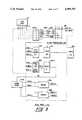
- FIG. 4is a block diagram of a serial input/output logic board.
- FIG. 5is a block diagram of a control module board.
- FIG. 7 sheets one (1) and two (2)show diagram of the software which controls the system during extraction and inserting of logic boards.
- FIG. 1is an overall block diagram of a Transaction Processing System 1 which includes a communication network 8 and a number of Network Access Controllers (NAC) 3a to 3n, each coupled to communications network 8 by communication lines 16-l through 16-n respectively.
- Each NAC 3a through 3nincludes a communication server unit (CSU) 2a through 2n and a general purpose computer 6a through 6n respectively.
- CSU 2acommunicates with a number of user terminals 4 in point-to-point or multi-drop topologies, typically over a maximum of 144 lines.
- General purpose computer 6nis shown in FIG. 1 as a back-up computer to computer 6a.
- Terminal 4may share a single communication line as terminals 4a or bid for a terminal controller 5 as terminals 4b.
- a message from the user terminalis presented to the NAC 3a which includes the identity of the originating user terminal 4, and information from the user which identifies the transaction and service provider.
- the messageis acquired typically in a polled environment.
- the NAC 3apresents this information to communications network 8.
- the service provider 10on recognizing its identity code or address accepts the information, processes the transaction and accordingly responds with a transaction back through the communication network 8, the NAC 3, to the originating terminal 4.
- the CSU 2amay establish a connection to a remote computer 6n.
- the remote computer 6nmay be part of another NAC 3n and be controlling its own local CSU 2n.
- a NAC 3ais normally comprised of a computer 6a and a CSU 2a, it will under failure conditions be made up of a local CSU 2a, a remote CSU 2n, and a remote computer 6n.
- the computer 6a softwaremay support up to typically 12 CSU's 2a. It is therefore conceivable that the NAC 3a may be constructed with a single computer 6a and multiple CSU's 2a.
- the Network Management Systems 14control the operation of and provide facilities to aid in the management of the network 8.
- Systems 14provides directory service by keeping information on the characteristics and addresses of the NAC 3a through 3n configurations, and the fall back address.
- FIG. 2shows a block diagram of the CSU 2a.
- the 144 communication lines and associated terminals 4are coupled to relay modules 2-2a through relay modules 2-2f respectively.
- Each relay module 2-2a through 2-2fis made up of four banks of relays.
- Each bank of relaysservices up to six communication lines. The twenty-four banks of relays therefore connect to the 144 communication lines.
- Each relay module 2-2a through 2-2fconnects to a MODEM bank 2-4a through 2-4f respectively via 28 pairs of signal lines.
- Each MODEM bank 2-4a through 2-4fincludes twenty-eight MODEMS, twenty-four MODEMS connected to the twenty-four communication lines and four MODEMS as spares.
- Each MODEM module 2-4a through 2-4fis connected to its respective half of a serial I/O (SIO) 2-6a through 2-6f by 24 sets of channel signals, one set of signals for each MODEM.
- the four spare MODEM's from each MODEM module 2-4a through 2-4fare connected to spare SIO 2-6 for a total of 24 spare channels. Switching a spare MODEM into the system also switches in its spare SIO.
- Each half SIO 2-6a through 2-6fconverts the information on 24 channels received from the respective MODEM modules 2-4a through 2-4f to a parallel stream of characters which is placed on a VMEbus 2-8.
- the 16 signals on each full duplex channelincludes a transmitted data signal and a received data signal, each data signal carrying a stream of data bits.
- the remaining signalsare the normal handshaking signals of the CCITT V.24 recommendation.
- Each pair of SIO's 2-6a and 2-6b, 2-6c and 2-6d, and 2-6e and 2-6fprovides forty-eight fully programmable, full duplex multi-protocol serial data channels (of which only forty-eight are used).
- Each MODEM module 2-4a through 2-4fin addition to providing 24 channels to their respective SIO's 2-6a through 2-6f, also provides four spare channels to a spare SIO 2-6s for a total of 24 channels.
- the SIO 2-6sin turn connects to the twenty-four channels to the VMEbus 2-8.
- SIO 2-6sincludes SIO 7, 14, and 21 as spares.
- Control module 2-12provides signals to switch a terminal 4 from a communication path that is inoperative to a spare communication path by activating a selected relay in a relay module 2-2a through 2-2f .
- each relay module 2-2a through 2-2fincludes four banks of relays. Each bank of relays may switch any one of six terminals 4 to a spare MODEM in MODEM modules 2-4a through 2-4f .
- each of the MODEM modulesincludes twenty-eight MODEMS, twenty-four MODEMS for normal operation and four spare MODEMS for back-up operation.
- Power Supply 13provides ground +5 VDC, +/-12 VDC, and -48 VDC to the logic components.
- FIG. 3shows a typical relay module logic board 2-2a.
- 24 pairs of communication linesare connected to their respective MODEMS 301 through normally closed contacts of relays 211. If the system senses a disabled MODEM, then a relay driver in relay drivers 201 will energize the relay in relays 211 to switch the incoming communications line par to a spare MODEM of MODEMS 301.
- relay drivers 201typically includes six drivers, each driving one of six relays to control one of six pairs of communication lines.
- Each of the four relay drivers of relay drivers 201is enabled by a STROBE (STROBE 1, 2, 3, or 4) signal from a decoder 220, and the selected relay driver is activated by a DATA (DATA 1, 2, 3, 4, 5, or 6) signal from a decoder 221. Note that the relay drivers 201 are only activated to switch a communication line pair to a spare MODEM of MODEM 301.
- STROBESTROBE 1, 2, 3, or 4
- the control module 2-12When the system senses a bad communication line pair, the control module 2-12 enables decoders 220 and 221 to cause a switch to a spare MODEM via signals ENABLE and RYAD0-5.
- the control module 2-12request a remote line test by enabling decoders 220 and 221 to generate signal STROBERLT and DATA 1, 2, 3, or 4 signals which are applied to remote line test relay driver 207 which select the 1 of 4 relays of Relays 207-1 via signals PRLTC1, 2, 3 or 4. This switches the communication line pair that is connected to the spare MODEM to the control module 2-12 which in turn tests the communication line pair.
- the umbilical cord 11is plugged into a connector 300.
- Thisprovides +5 VD, +12 VD, and -12 VD to diodes 302, 304, and 306 respectively, which isolates their respective voltages.
- Ground and a RESET signalare also provided.
- the RESET signaldisables relay drivers 201 and 207. This provides external power to the relay module board 2-2a and also holds the logic in a known state so that when the edge connector 310 contacts break the normal power source to the board, and +5V and +/-12 V are still active, therefore no transient signals or arcing results.
- FIG. 4shows a typical SIO logic board 2-6a.
- V.24 communication signalsare received from MODEMS 401 by Serial Communication Controllers 601.
- One SIO board 2-6aincludes four dual channel Serial Communication Controllers 601 which communicates with the VME bus 2-8 via data registers 605.
- Control logic 608provides address and control signals between the VME bus 2-8 and the Controllers 601.
- the umbilical cord 11 from power supply 13is plugged into connector 400 when an SIO board 2-6a is to be removed or inserted.
- the RESET signal applied to data registers 605 and control logic 608suspend SIO operation by disabling the control logic 608 and forcing the Data Registers 604 output signals low.
- the VME bus 2-8is disabled when bit 5 from the data registers 605 is low.
- edge connector 410makes or breaks the normal +5 V and +/-12 V circuits. Since the SIO board 2-6a is held in a known state by ground, the +5 VD and +/-12 VD, through diodes 402, 406, and 408, respectively, and the RESET signal, no transient signals or arcing results.
- FIG. 5shows the Control Module logic board 2-12.
- Network Processor 2-10a or 2-10bis designated as a master.
- the mastersends signals to microprocessors 120 or 121 to indicate, for example, that a spare MODEM should replace an existing MODEM.
- Microprocessor 120 or 121then sends the RYAD 0-5 signals and the ENABLE signals to the relay module boards 2-2a through 2-2f to energize a relay to switch a communication line signal pair to the spare MODEM.
- FIG. 6shows a block diagram of the network processor 2-10a which transfers information between the VME bus 2-8 and the computer 6a.
- Network processor 2-10balso transfers information between the VME bus 2-8 and the computer 6a.
- the CPU 100 bootstrap and quality logic testsare stored in PROM 103.
- the data received from the VME bus 2-8may be stored in a local memory 105 via transceiver 106 at an address specified by the VME bus 2-8 address signals which are applied to local memory 105 via a transceiver 107 and an address MUX 108.
- the datais read out of local memory 105 by CPU 100 generating an address over CPU address bus 111 and address MUX 108.
- the addressmay also be placed on the VME bus 2-8 via a transceiver 109 and transceiver 107.
- the application softwareis stored in the local memory 105.
- Datais received from computer 6 over the V.24 channel, and channel B of the SCC 101. It is transferred over CPU data bus 110 to local memory 105 and then to the VME bus 2-8 via transceiver 104 and transceiver 106.
- Computer 6ais responsible for the overall control of the NAC 3a.
- a microcode in PROM 103supports a self test operation and enables itself to be booted from computer 6a.
- computer 6adirects all CSU 2a actions. If the CSU 2a loses contact with computer 6a, it will establish contact with computer 6n.
- computer 6acontrols the polling of communication lines provides configuration and control commands, such as resolving faults detected in the CSU 2a by switching spare equipment into active service to replace failed or failing equipment.
- network processor 2-10aThe operation of network processor 2-10a is described above. However, network processor 2-10b is a duplicate of network processor 2-10a . Both network processors 2-10a and 2-10b may share the load or any portions of the load. For example, network processor 2-10a may communicate with SIO 2-6a and 2-6b, and network processor 2-10b may communicate with SIO 2-6c, 2-6d, 2-6e, and 2-6f. Either network processor 2-10a or 2-10b may communicate with SIO 2-6a through 2-6f if one is out of service.
- a control panel 620 including a "hot insert” pushbutton switch 616is plugged into the master network 2-10a or 2-10b.
- the switch 616is depressed a processor first time to signal the master network processor 2-10a or 2-10b that a logic board is to be removed or installed.
- the master network processor 2-10a or 2-10binitiates a software routine which in combination with a corresponding software routine which runs on the computer 6a shuts down the CSU 2a in an orderly fashion and will not, for a short period of time, typically one minute, receive further transactions from the terminals 4 or from the communications network 8.
- the logic to perform this functionis shown in FIG. 6 and the matching software is shown in block diagram form in FIG. 7.
- switch 616When the logic board is replaced and the umbilical cord removed, the operator again depresses switch 616 to indicate to the system that the logic board is plugged into its backplane connector. Again, the INHIBI signal initiates a CPU 100 interrupt and the subsequent acknowledge of the interrupt. However, the system knows this is the second depression of switch 616 and the software takes action as described in FIG. 7.
- FIG. 7is the block diagram showing the software flow through the master network processor 2-10a or 2-10b and the computer 6a.
- the master network processor 2-10a or 2-10binforms the computer 6a in block 700 that a logic board is about to be installed or replaced.
- Block 702receives the message and decision block 704 tests if this is a "hot insertion" message. If not, then the computer 6a branches to another processing routine in block 705.
- the computer 6asends a message to the CSU Network Processors 2-10a and 2-10b to stop VME bus 2-8 activity.
- Block 708receives the message and in decision block 710 tests if the message relates to the "hot insertion" operation. If not, then block 712 provides another routine. If this is a "hot insertion” operation, then decision block 714 programs the SIO's 2-6 to disable the VME bus 2-8.
- Block 716then sends a message to the computer 6a indicating that the CSU 2a has stopped all activity and sets the LED 618 flashing in block 722. Meanwhile, block 718 and decision block 720 have been looping, waiting for the message that the CSU 2a has stopped all activity.
- Block 728starts a timer T1 in CPU 6a.
- the Master Network Processor 2-10a and 2-10bawaits either a signal for the switch 616 indicating that the logic board is inserted into the backplane or that the timer T1 has timed out.
- the master network processor 2-10a or 2-10breceives the second switch 616 signal, indicating that the new logic board is installed and the umbilical cord 11 removed, then a message is generated which is received by block 730.
- Block 730calls block 732 if the message was received from block 726 indicating that the board is replaced and then "hot insertion" switch 616 was activated or the timer T1 timed out.
- the timeris usually set to restart functions in typically one minute whether or not the logic board was inserted. There is sufficient redundancy in the system to assure proper operation, even with a logic board inactive. This minimizes the time CSU 2a is off-line.
- Block 732therefore informs both network processors 2-10a and 2-10b to resume VME bus 2-8 activity.
- block 734the VME bus 2-8 and all SIO's are enabled. Then decision block 736 tests for errors. If errors were found, block 738 switches the error components out of the system and informs the computer 6a. If there are no errors, then block 744 waits for a message from the computer 6a.
- Decision block 740waits for a command from the operator to either perform other processing in block 748 or to reconfigure the CSU 2-2a.
- block 744receives the message from block 742, it calls on decision block 746 to either perform other processing in block 750 or to reconfigure and bring CSU 2-2a on-line in block 752 and turn the LED 618 to solid green.
Landscapes
- Engineering & Computer Science (AREA)
- Theoretical Computer Science (AREA)
- General Engineering & Computer Science (AREA)
- Physics & Mathematics (AREA)
- General Physics & Mathematics (AREA)
- Quality & Reliability (AREA)
- Computer Hardware Design (AREA)
- Computer And Data Communications (AREA)
- Hardware Redundancy (AREA)
- Data Exchanges In Wide-Area Networks (AREA)
- Small-Scale Networks (AREA)
Abstract
Description
The following U.S. patent applications are assigned to the same assignee and are related to the instant application.
1. Resilient Data Communications System by Lance McNally, Anthony J. Booth, and Peter Morley was filed on Dec. 23, 1987 and has Ser. No. 07/137,315, now U.S. Pat. No. 4,879,716.
2. Modem Backplane Interconnections by Lance McNally and Peter Morley was filed on 7/15/88 and has Ser. No. 07/219,941 now U.S. Pat. No. 4,831,634.
1. Field of the Invention
This invention relates primarily to the field of data communications systems, and more specifically to the extraction and insertion of logic boards from a backplane without removing power from the system.
2. Description of the Prior Art
Data communication systems have a high uptime requirement. This is particularly true when a large number of terminals are connected into the system. Data communications systems have solved the high uptime need by employing multiple processors for communication line message processing. If one of the processors requires service, it is taken off line by maintenance personnel while the remaining processor or processors remain active. This assures that the system will remain operative but possibly with lower throughput.
Other systems are designed with redundant circuits which would automatically be switched out of the system when defective. The defective circuit would be replaced during the late night scheduled maintenance period when the entire system is shut down.
Accordingly, it is an object of the invention to have an improved data communication system with high uptime.
It is another object of the invention to have an improved data communication system with improved throughput.
It is still another object of the invention to have an improved data communication system with improved maintainability.
It is yet another objective of the invention to have an improved data communication with improved apparatus for replacing defective logic boards or installing new logic boards to expand the system without power shutdown.
A real time, high uptime transaction processing system includes many user terminals communicating with service providers via a communication network.
Groups of terminals are connected to the communications network through a Network Access Control (NAC) which includes a Communications Server Unit (CSU) and a computer. The CSU includes a number of logic boards namely relay module boards, system input output boards, a control module board, and network processor boards.
When a defective board is replaced or a board providing system expansion is installed, it is desirable to replace or add the board without powering the system down. Accordingly, a portable control panel (PCP) having a "hot insert" button is plugged into the master CSU processor board. Depressing the button causes the master CSU processor to notify the NAC computer that a board is to be replaced or inserted. The NAC computer instructs the master CSU processor to halt VME bus activity. When VME bus activity has stopped as evidenced by an indicator light on the CPU, an umbilical cord from a power supply is inserted into a connector on the failed board to provide an auxiliary source of power. The defective logic board is then physically removed from the system.
Since the defective logic board is held in a known powered up-state when it is unplugged from the backplane, there is no arcing at the backplane connector and no logic spikes generated to impact other logic boards.
The replacement board is installed by first inserting the umbilical cord into its connector signal to power it up in a known state and then inserting the board into its backplane connector.
The umbilical cord provides ground, a reset signal, and the logic board voltages +5 VDC and +/-12 VDC. The board therefore remains powered up while it is unplugged from its backplane connector. This eliminates arcing and spurious signals.
The umbilical cord is unplugged and the "hot insert" button is again depressed. This results in the computer notifying the network processor to restart the VME bus activity.
FIG. 1 shows an block diagram of a Transaction Processing System.
FIG. 2 is a block diagram of a Communication Service Unit.
FIG. 3 is a block diagram of a relay module logic board.
FIG. 4 is a block diagram of a serial input/output logic board.
FIG. 5 is a block diagram of a control module board.
FIG. 6 is a block diagram of a network processor logic board.
FIG. 7 sheets one (1) and two (2) show diagram of the software which controls the system during extraction and inserting of logic boards.
FIG. 1 is an overall block diagram of aTransaction Processing System 1 which includes acommunication network 8 and a number of Network Access Controllers (NAC) 3a to 3n, each coupled tocommunications network 8 by communication lines 16-l through 16-n respectively. EachNAC 3a through 3n includes a communication server unit (CSU) 2a through 2n and ageneral purpose computer 6a through 6n respectively. EachCSU 2a communicates with a number ofuser terminals 4 in point-to-point or multi-drop topologies, typically over a maximum of 144 lines.General purpose computer 6n is shown in FIG. 1 as a back-up computer tocomputer 6a. Terminal 4 may share a single communication line as terminals 4a or bid for aterminal controller 5 asterminals 4b.
Also coupled tocommunication network 8 are a number ofservice providers 10, and networkmanagement computer systems 14.
A message from the user terminal is presented to theNAC 3a which includes the identity of the originatinguser terminal 4, and information from the user which identifies the transaction and service provider. The message is acquired typically in a polled environment. TheNAC 3a presents this information tocommunications network 8. Theservice provider 10 on recognizing its identity code or address accepts the information, processes the transaction and accordingly responds with a transaction back through thecommunication network 8, the NAC 3, to the originatingterminal 4.
The NAC's 3a through 3n are the network nodes, geographically dispersed to provide local connections to theterminals 4 at the user's premises. The NAC's 3a through 3n are predominantly located in telephone exchanges but a small proportion may be located on the customer's premises, particularly when the premises serve many users.
TheNAC 3a consists of two major functional units, thecomputer 6a and theCSU 2a. Thecomputer 6a is responsible for the overall control of theNAC 3a, namely for relaying the information between theterminals 4 and theservice providers 10 and for providing configuration and control information, such as detecting and reporting defective communication links.
TheCSU 2a is constructed such that all critical components are duplicated. In the event of an internal failure, redundant components are activated to insure the continuation of service pending correction of the problem. However, theCSU 2a is dependent on the control services ofcomputer 6a which initiates the corrective actions.
In the event of a failure incomputer 6a or its connections tocommunications network 8, theCSU 2a may establish a connection to aremote computer 6n. Theremote computer 6n may be part of anotherNAC 3n and be controlling its ownlocal CSU 2n. Although aNAC 3a is normally comprised of acomputer 6a and aCSU 2a, it will under failure conditions be made up of alocal CSU 2a, aremote CSU 2n, and aremote computer 6n. Thecomputer 6a software may support up to typically 12 CSU's 2a. It is therefore conceivable that theNAC 3a may be constructed with asingle computer 6a and multiple CSU's 2a.
TheNetwork Management Systems 14 control the operation of and provide facilities to aid in the management of thenetwork 8.Systems 14 provides directory service by keeping information on the characteristics and addresses of theNAC 3a through 3n configurations, and the fall back address.
FIG. 2 shows a block diagram of theCSU 2a. The 144 communication lines and associatedterminals 4 are coupled to relay modules 2-2a through relay modules 2-2f respectively. Each relay module 2-2a through 2-2f is made up of four banks of relays. Each bank of relays services up to six communication lines. The twenty-four banks of relays therefore connect to the 144 communication lines. Each relay module 2-2a through 2-2f connects to a MODEM bank 2-4a through 2-4f respectively via 28 pairs of signal lines. Each MODEM bank 2-4a through 2-4f includes twenty-eight MODEMS, twenty-four MODEMS connected to the twenty-four communication lines and four MODEMS as spares.
Each MODEM module 2-4a through 2-4f is connected to its respective half of a serial I/O (SIO) 2-6a through 2-6f by 24 sets of channel signals, one set of signals for each MODEM. The four spare MODEM's from each MODEM module 2-4a through 2-4f are connected to spare SIO 2-6 for a total of 24 spare channels. Switching a spare MODEM into the system also switches in its spare SIO.
Each half SIO 2-6a through 2-6f converts the information on 24 channels received from the respective MODEM modules 2-4a through 2-4f to a parallel stream of characters which is placed on a VMEbus 2-8. The 16 signals on each full duplex channel includes a transmitted data signal and a received data signal, each data signal carrying a stream of data bits. The remaining signals are the normal handshaking signals of the CCITT V.24 recommendation.
Each pair of SIO's 2-6a and 2-6b, 2-6c and 2-6d, and 2-6e and 2-6f provides forty-eight fully programmable, full duplex multi-protocol serial data channels (of which only forty-eight are used).
Each MODEM module 2-4a through 2-4f in addition to providing 24 channels to their respective SIO's 2-6a through 2-6f, also provides four spare channels to a spare SIO 2-6s for a total of 24 channels. The SIO 2-6s in turn connects to the twenty-four channels to the VMEbus 2-8. SIO 2-6s includesSIO 7, 14, and 21 as spares.
Also connected to the VMEbus 2-8 are duplicate network processors 2-10a 2-10b. Network processor 2-10a includes a communication controller A, a communication controller B and a microprocessor and common logic for control of both communication controllers A and B. Communication controller A is connected tocomputer computer Computer 6a assigns network processor 2-10a or 2-10b as a master Ifcomputer 6a determines that processor 2-10b as the master then it processes all data.
Control module 2-12 provides signals to switch a terminal 4 from a communication path that is inoperative to a spare communication path by activating a selected relay in a relay module 2-2a through 2-2f . Note that each relay module 2-2a through 2-2f includes four banks of relays. Each bank of relays may switch any one of sixterminals 4 to a spare MODEM in MODEM modules 2-4a through 2-4f . Note that each of the MODEM modules includes twenty-eight MODEMS, twenty-four MODEMS for normal operation and four spare MODEMS for back-up operation.
Network processor 2-10b includes communication controller C and communication controller D as well as its microprocessor and common logic. Communication controller C is connected to control module 2-12 via a RS422 interface.
FIG. 3 shows a typical relay module logic board 2-2a. During normal operation, 24 pairs of communication lines are connected to theirrespective MODEMS 301 through normally closed contacts ofrelays 211. If the system senses a disabled MODEM, then a relay driver inrelay drivers 201 will energize the relay inrelays 211 to switch the incoming communications line par to a spare MODEM ofMODEMS 301. Note thatrelay drivers 201 typically includes six drivers, each driving one of six relays to control one of six pairs of communication lines.
Each of the four relay drivers ofrelay drivers 201 is enabled by a STROBE (STROBE 1, 2, 3, or 4) signal from adecoder 220, and the selected relay driver is activated by a DATA (DATA decoder 221. Note that therelay drivers 201 are only activated to switch a communication line pair to a spare MODEM ofMODEM 301.
When the system senses a bad communication line pair, the control module 2-12 enablesdecoders decoders DATA test relay driver 207 which select the 1 of 4 relays of Relays 207-1 via signals PRLTC1, 2, 3 or 4. This switches the communication line pair that is connected to the spare MODEM to the control module 2-12 which in turn tests the communication line pair.
When the relay module board 2-2a is to be removed or added, theumbilical cord 11 is plugged into aconnector 300. This provides +5 VD, +12 VD, and -12 VD todiodes relay drivers edge connector 310 contacts break the normal power source to the board, and +5V and +/-12 V are still active, therefore no transient signals or arcing results.
The entire shutdown and startup sequences are described in connection with FIGS. 6 and 7.
FIG. 4 shows a typical SIO logic board 2-6a. During normal operations, V.24 communication signals are received from MODEMS 401 bySerial Communication Controllers 601. One SIO board 2-6a includes four dual channelSerial Communication Controllers 601 which communicates with the VME bus 2-8 via data registers 605. Control logic 608 provides address and control signals between the VME bus 2-8 and theControllers 601.
Theumbilical cord 11 frompower supply 13 is plugged intoconnector 400 when an SIO board 2-6a is to be removed or inserted. The RESET signal applied todata registers 605 and control logic 608 suspend SIO operation by disabling the control logic 608 and forcing the Data Registers 604 output signals low. The VME bus 2-8 is disabled whenbit 5 from the data registers 605 is low.
Again,edge connector 410 makes or breaks thenormal + 5 V and +/-12 V circuits. Since the SIO board 2-6a is held in a known state by ground, the +5 VD and +/-12 VD, throughdiodes
FIG. 5 shows the Control Module logic board 2-12. Network Processor 2-10a or 2-10b is designated as a master. The master sends signals tomicroprocessors Microprocessor
The remote line testing function is enabled by sending the ENABLE and RAYAD 0-5 signals toRLT 136 which generates the RLT signal.
Theumbilical cord 11 frompower supply 13 is plugged intoconnector 500 and will hold themicroprocessor edge connector 510 since power is provided by +5 VD, +/-12 VDC, and ground throughdiodes
FIG. 6 shows a block diagram of the network processor 2-10a which transfers information between the VME bus 2-8 and thecomputer 6a. Network processor 2-10b also transfers information between the VME bus 2-8 and thecomputer 6a.
Data from the VME bus 2-8 appears on theCPU data bus 110 via atransceiver 106 and atransceiver 104. The sixteen bit data is received by aCPU 100 and conditions the Serial Communication Controller (SCC's) 101 and 102 to receive the data for transfer tocomputer 6a over a channel A V.24 interface or transfer the data to the control module 2-12 over a balanced interface from channel B ofSCC
TheCPU 100 bootstrap and quality logic tests are stored inPROM 103. The data received from the VME bus 2-8 may be stored in alocal memory 105 viatransceiver 106 at an address specified by the VME bus 2-8 address signals which are applied tolocal memory 105 via atransceiver 107 and anaddress MUX 108. The data is read out oflocal memory 105 byCPU 100 generating an address over CPU address bus 111 and addressMUX 108. The address may also be placed on the VME bus 2-8 via atransceiver 109 andtransceiver 107. The application software is stored in thelocal memory 105.
Data is received fromcomputer 6 over the V.24 channel, and channel B of theSCC 101. It is transferred overCPU data bus 110 tolocal memory 105 and then to the VME bus 2-8 viatransceiver 104 andtransceiver 106.
The operation of network processor 2-10a is described above. However, network processor 2-10b is a duplicate of network processor 2-10a . Both network processors 2-10a and 2-10b may share the load or any portions of the load. For example, network processor 2-10a may communicate with SIO 2-6a and 2-6b, and network processor 2-10b may communicate with SIO 2-6c, 2-6d, 2-6e, and 2-6f. Either network processor 2-10a or 2-10b may communicate with SIO 2-6a through 2-6f if one is out of service.
In normal operation, the primary role of theCPU 6a is to relay messages between theTerminals 4 and theservice providers 10.
A control panel 620 including a "hot insert"pushbutton switch 616 is plugged into the master network 2-10a or 2-10b. Theswitch 616 is depressed a processor first time to signal the master network processor 2-10a or 2-10b that a logic board is to be removed or installed. The master network processor 2-10a or 2-10b initiates a software routine which in combination with a corresponding software routine which runs on thecomputer 6a shuts down theCSU 2a in an orderly fashion and will not, for a short period of time, typically one minute, receive further transactions from theterminals 4 or from thecommunications network 8. The logic to perform this function is shown in FIG. 6 and the matching software is shown in block diagram form in FIG. 7.
Referring to FIG. 6, depression ofswitch 616 generates a signal INHIBI which is applied to the interruptlogic 614 to generate an interrupt signal INTERRUPT and a SWITCH signal. TheCPU 100 accepts the interrupt by generating an ACKNOWLEDGE signal which is applied to an acknowledgelogic 612. Signal INHIB2 from interruptlogic 614 indicates a logic board replacement or installation option. The SWITCHsignal conditions CPU 100 to control abi-color LED 618.
Acknowledgelogic 612 then initiates an AUTVEC signal which causes theCPU 100 to initiate the software routine of FIG. 7. When the operation is halted as shown byLED 618 flashing between green to red, theumbilical cord 11 is plugged intoconnector 600. If the Slave Network Processor 2-10a or 2-10b or any other logic board is to be replaced, then the umbilical cord is plugged into their respective connector; in the case of the network processor logic board,connector 600. This provides power to the logic board after it is unplugged fromconnector 610 viadiodes CPU 100 to suspend operation.
When the logic board is replaced and the umbilical cord removed, the operator again depressesswitch 616 to indicate to the system that the logic board is plugged into its backplane connector. Again, the INHIBI signal initiates aCPU 100 interrupt and the subsequent acknowledge of the interrupt. However, the system knows this is the second depression ofswitch 616 and the software takes action as described in FIG. 7.
When the system is shutting down theCPU 100 under software control, stores a SWCONT signal in aregister 622 to cause thebi-color LED 618 to flash between green and red under control of signal LITEUP. When the system is restarted, theCPU 100, under software control, resets register 622 to cause theLED 618 to go to solid green. This indicates to the operator that the logic board replacement or installation operation is completed.
FIG. 7 is the block diagram showing the software flow through the master network processor 2-10a or 2-10b and thecomputer 6a.
When theswitch 616 is depressed initially and theCPU 100 receives the AUTVEC signal as shown in FIG. 6, the master network processor 2-10a or 2-10b informs thecomputer 6a inblock 700 that a logic board is about to be installed or replaced.
If the message received from the Master Network is a "hot insertion" message, then inblock 706 thecomputer 6a sends a message to the CSU Network Processors 2-10a and 2-10b to stop VME bus 2-8 activity.
Block 728 starts a timer T1 inCPU 6a. The Master Network Processor 2-10a and 2-10b awaits either a signal for theswitch 616 indicating that the logic board is inserted into the backplane or that the timer T1 has timed out.
In block 726, the master network processor 2-10a or 2-10b receives thesecond switch 616 signal, indicating that the new logic board is installed and theumbilical cord 11 removed, then a message is generated which is received by block 730. Block 730 calls block 732 if the message was received from block 726 indicating that the board is replaced and then "hot insertion"switch 616 was activated or the timer T1 timed out. The timer is usually set to restart functions in typically one minute whether or not the logic board was inserted. There is sufficient redundancy in the system to assure proper operation, even with a logic board inactive. This minimizes thetime CSU 2a is off-line. Block 732 therefore informs both network processors 2-10a and 2-10b to resume VME bus 2-8 activity.
In block 734, the VME bus 2-8 and all SIO's are enabled. Then decision block 736 tests for errors. If errors were found, block 738 switches the error components out of the system and informs thecomputer 6a. If there are no errors, then block 744 waits for a message from thecomputer 6a.
Decision block 740 waits for a command from the operator to either perform other processing in block 748 or to reconfigure the CSU 2-2a. When block 744 receives the message from block 742, it calls on decision block 746 to either perform other processing in block 750 or to reconfigure and bring CSU 2-2a on-line in block 752 and turn theLED 618 to solid green.
While the invention has been shown and described with reference to the preferred embodiment thereof, it will be understood by those skilled in the art that the above and other changes in form and detail may be made therein without departing from the spirit and scope of the invention.
Claims (5)
1. A method of replacing a logic board plugged into a backplane connector in an on-line system without powering down, including the steps of:
A--inserting an end of an umbilical cord into a connector of said logic board to provide auxiliary logic power and a reset signal to disable the logic of said logic board;
B--actuating a hot insert switch to generate a first signal;
C--receiving said first signal by a first computer and sending a hot insert message to a second computer;
D sending a message by said second computer to said first computer to shut down all activity;
E--sending a message by said first computer to said second computer that all activity is stopped, said first computer setting an indicator to a first state;
F--starting a timer in said second computer;
G--removing said logic board from said backplane connector;
H--removing said umbilical cord end from said logic board and inserting it into a connector of a replacement logic board;
I--inserting said replacement logic board into said backplane connector;
J--removing said umbilical cord end from said connector of said replacement logic board;
K--said first computer awaiting said first signal generated by a second actuation of said hot insert switch indicating that said replacement logic board has been inserted into said backplane connector and said second computer awaiting a signal indicating a timeout;
L--responding by said first computer of said second occurence of said first signal or a message from said second computer indicating a timeout to restart all activity and setting said indicator to a second state.
2. A method of adding a logic board to a backplane connector in an on-line system without powering down including the steps of:
A--inserting an end of umbilical cord into a connector of said logic board to provide auxiliary logic power and a reset signal to disable the logic of said logic board;
B--actuating a hot insert switch to generate a first signal;
C--receiving said first signal by a first computer and sending a hot insert message to a second computer;
D--sending a message by said second computer to said first computer to shut down all activity;
E--sending a message by said first computer to said second computer indicating that all activity is stopped said first computer setting an indicator to a first state;
F--starting a timer in said second computer;
G--inserting said logic board into said backplane connector;
H--removing said umbilical cord end from said connector of said logic board;
I--said first computer awaiting by said first signal generated by a second actuation of said hot insert switch indicating that said logic board has been inserted into said backplane connector and said second computer awaiting by a signal indicating a timeout;
J--responding by said first computer to said second occurence of said first signal or a message from said second computer indicating a timeout to restart all activity and setting said indicator to a second state.
3. Apparatus for removing a logic board in an on-line system without powering down comprising:
a power supply for providing a first plurality of voltages and a second plurality of voltages with a reset signal,
a backplane coupled to said power supply for receiving said first plurality of voltages, said backplane including a plurality of connectors,
a plurality of logic boards each coupled to said backplane by one of said plurality of connectors for receiving said first plurality of voltages, one of said plurality of logic boards requiring replacement,
an umbilical cord coupled to said power supply and a first connector on said one of said plurality of logic boards for providing said second plurality of voltages with said reset signal,
said one of said plurality of logic boards including logic means responsive to said reset signal and said second plurality of voltages for remaining in a passive state when unplugged from said one of said plurality of connectors.
4. Apparatus for adding a logic board in an on-line system without powering down comprising:
a power supply for providing a first plurality of voltages and a second plurality of voltages with a reset signal,
a backplane coupled to said power supply for receiving said first plurality of voltages, said backplane including a plurality of connectors,
a plurality of logic boards each coupled to said backplane by one of said plurality of connectors for receiving said first plurality of voltages,
an umbilical cord coupled to said power supply and a first connector on said one of said plurality of logic boards to be plugged into said one of said plurality of connectors for providing said second plurality of voltages without reset signal,
said one of said plurality of logic boards including logic means responsive to said reset signal and said second plurality of voltages for remaining in a passive state when being plugged into said one of said plurality of connectors.
5. Apparatus for replacing a logic board in an on-line system without powering down comprising:
a power supply for providing a first plurality of voltages and a second plurality of voltages with a reset signal,
a backplane coupled to said power supply for receiving said first plurality of voltages, said backplane including a plurality of connectors,
a plurality of logic boards each coupled to said backplane by one of said plurality of connectors, said plurality of logic boards including a plurality of network processor boards, one of said plurality of network processor boards including a hot insert switch, and one of said plurality of logic boards requiring replacement,
an umbilical cord coupled to said power supply and a first connector on said one of said plurality of logic boards to be plugged into said one of said plurality of connectors for providing said second plurality of voltages with said reset signal, said one of said plurality of logic boards having means responsive to said reset signal and said second plurality of voltages for remaining in a passive state,
said one of said plurality of network processor boards including logic means responsive to a signal from said hot insert switch for generating a first message indicating that one of said logic boards requires replacement,
a central processor unit coupled to said logic means of said one of said plurality of network processor boards and having means for receiving said first message for generating a second message, said central processor unit further being responsive to said first message for starting a timer for generating a timer signal after a predetermined time,
said logic means of said one of said plurality of network processor boards being responsive to said second message for stopping bus activity,
said logic means being further responsive to a second occurrence of said signal from said hot insert switch indicating the replacement of said one of said logic boards and the removal of said umbilical cord for generating a third message,
said receiving means of said central processor unit being responsive to said third message if said timer signal was not received, or responsive to said timer signal if said third message was not received for generating a fourth message,
said logic means of being responsive to said fourth message for enabling said bus.
Priority Applications (3)
| Application Number | Priority Date | Filing Date | Title |
|---|---|---|---|
| US07/219,958US4999787A (en) | 1988-07-15 | 1988-07-15 | Hot extraction and insertion of logic boards in an on-line communication system |
| EP19890111289EP0350674A3 (en) | 1988-07-15 | 1989-06-21 | Method for hot extraction and insertion of logic boards in an on-line communication system and apparatus therefor |
| AU38010/89AAU617491B2 (en) | 1988-07-15 | 1989-07-11 | Hot extraction and insertion of logic boards in an on-line communication system |
Applications Claiming Priority (1)
| Application Number | Priority Date | Filing Date | Title |
|---|---|---|---|
| US07/219,958US4999787A (en) | 1988-07-15 | 1988-07-15 | Hot extraction and insertion of logic boards in an on-line communication system |
Publications (1)
| Publication Number | Publication Date |
|---|---|
| US4999787Atrue US4999787A (en) | 1991-03-12 |
Family
ID=22821434
Family Applications (1)
| Application Number | Title | Priority Date | Filing Date |
|---|---|---|---|
| US07/219,958Expired - Fee RelatedUS4999787A (en) | 1988-07-15 | 1988-07-15 | Hot extraction and insertion of logic boards in an on-line communication system |
Country Status (3)
| Country | Link |
|---|---|
| US (1) | US4999787A (en) |
| EP (1) | EP0350674A3 (en) |
| AU (1) | AU617491B2 (en) |
Cited By (134)
| Publication number | Priority date | Publication date | Assignee | Title |
|---|---|---|---|---|
| US5210855A (en)* | 1989-06-09 | 1993-05-11 | International Business Machines Corporation | System for computer peripheral bus for allowing hot extraction on insertion without disrupting adjacent devices |
| US5317707A (en)* | 1989-10-20 | 1994-05-31 | Texas Instruments Incorporated | Expanded memory interface for supporting expanded, conventional or extended memory for communication between an application processor and an external processor |
| US5317697A (en)* | 1991-07-31 | 1994-05-31 | Synernetics Inc. | Method and apparatus for live insertion and removal of electronic sub-assemblies |
| US5349689A (en)* | 1988-11-21 | 1994-09-20 | Oki Electric Industry Co., Ltd. | Apparatus for maintaining reset on microprocessor until after electrical chattering from connection of removable memory cartridge has ceased |
| US5414814A (en)* | 1992-05-08 | 1995-05-09 | The United States Of America As Represented By The Secretary Of The Navy | I/O interface between VME bus and asynchronous serial data computer |
| US5421018A (en)* | 1988-07-11 | 1995-05-30 | Canon Kabushiki Kaisha | Data communication method and apparatus having improved control over a detachable terminal device |
| US5432916A (en)* | 1992-02-29 | 1995-07-11 | International Business Machines Corp. | Precharge for non-disruptive bus live insertion |
| US5511171A (en)* | 1993-02-26 | 1996-04-23 | 3Com Corporation | Apparatus for live bus insertion of add-on devices |
| US5519264A (en)* | 1992-12-02 | 1996-05-21 | Emc Corporation | Inrush current limiter |
| US5526493A (en)* | 1993-06-03 | 1996-06-11 | Dell Usa | Docking detection and suspend circuit for portable computer/expansion chassis docking system |
| US5530302A (en)* | 1994-01-13 | 1996-06-25 | Network Systems Corporation | Circuit module with hot-swap control circuitry |
| US5555510A (en)* | 1994-08-02 | 1996-09-10 | Intel Corporation | Automatic computer card insertion and removal algorithm |
| US5564024A (en)* | 1994-08-02 | 1996-10-08 | Pemberton; Adam C. | Apparatus for connecting and disconnecting peripheral devices to a powered bus |
| US5572141A (en)* | 1994-03-09 | 1996-11-05 | At&T Global Information Solutions Company | Memory metal hot plug connector and method |
| US5604873A (en)* | 1994-12-28 | 1997-02-18 | Intel Corporation | Circuitry for controlling power application to a hot docking SCSI SCA disk drive |
| US5625777A (en)* | 1990-11-29 | 1997-04-29 | Fujitsu Limited | Data storage system having plural external storage units capable of disconnection while keeping system power energized |
| US5632020A (en)* | 1994-03-25 | 1997-05-20 | Advanced Micro Devices, Inc. | System for docking a portable computer to a host computer without suspending processor operation by a docking agent driving the bus inactive during docking |
| US5714809A (en)* | 1995-10-12 | 1998-02-03 | International Business Machines Corporation | Soft switching circuit with current-mode control |
| US5740378A (en)* | 1995-08-17 | 1998-04-14 | Videoserver, Inc. | Hot swap bus architecture |
| US5758101A (en)* | 1995-07-14 | 1998-05-26 | Alliance Peripheral Systems, Inc. | Method and apparatus for connecting and disconnecting peripheral devices to a powered bus |
| US5761529A (en)* | 1994-10-18 | 1998-06-02 | Lanier Worldwide Inc. | Method for storing and retreiving files by generating an array having plurality of sub-arrays each of which include a digit of file identification numbers |
| US5781794A (en)* | 1993-12-01 | 1998-07-14 | Fujitsu Limited | Data processing system having an addition unit for preparing new control tables for new hardware modules and dynamically adding the tables to the present control tables |
| US5822196A (en)* | 1996-06-05 | 1998-10-13 | Compaq Computer Corporation | Securing a card in an electronic device |
| US5832237A (en)* | 1995-05-17 | 1998-11-03 | Samsung Electronics Co., Ltd. | Portable computer system and method for controlling a power of system |
| US5875308A (en)* | 1997-06-18 | 1999-02-23 | International Business Machines Corporation | Peripheral component interconnect (PCI) architecture having hot-plugging capability for a data-processing system |
| US5889965A (en)* | 1997-10-01 | 1999-03-30 | Micron Electronics, Inc. | Method for the hot swap of a network adapter on a system including a dynamically loaded adapter driver |
| US5892928A (en)* | 1997-05-13 | 1999-04-06 | Micron Electronics, Inc. | Method for the hot add of a network adapter on a system including a dynamically loaded adapter driver |
| US5920707A (en)* | 1996-01-29 | 1999-07-06 | Nec Corporation | Bus controller and method therefor for supporting a live-line insertion/disconnection in a synchronous bus |
| US5922060A (en)* | 1996-12-31 | 1999-07-13 | Compaq Computer Corporation | Expansion card insertion and removal |
| US5943482A (en)* | 1996-06-05 | 1999-08-24 | Compaq Computer Corporation | Expansion card insertion and removal |
| US5962933A (en)* | 1997-05-13 | 1999-10-05 | Micron Electronics, Inc. | Computer fan speed control method |
| US5987554A (en)* | 1997-05-13 | 1999-11-16 | Micron Electronics, Inc. | Method of controlling the transfer of information across an interface between two buses |
| US5990582A (en)* | 1997-05-13 | 1999-11-23 | Micron Electronics, Inc. | Computer fan speed control device |
| US6003100A (en)* | 1995-06-13 | 1999-12-14 | Advanced Micro Devices, Inc. | User-removable central processing unit card for an electrical device |
| US6006298A (en)* | 1995-03-24 | 1999-12-21 | Nec Corporation | On-line module replacement system |
| US6009541A (en)* | 1997-10-01 | 1999-12-28 | Micron Electronics, Inc. | Apparatus for performing an extensive diagnostic test in conjunction with a bios test routine |
| US6035420A (en)* | 1997-10-01 | 2000-03-07 | Micron Electronics, Inc. | Method of performing an extensive diagnostic test in conjunction with a bios test routine |
| US6046742A (en)* | 1997-05-13 | 2000-04-04 | Micron Electronics, Inc. | Display of system information |
| US6058445A (en)* | 1997-05-13 | 2000-05-02 | Micron Electronics, Inc. | Data management method for adding or exchanging components on a running computer |
| US6065053A (en)* | 1997-10-01 | 2000-05-16 | Micron Electronics, Inc. | System for resetting a server |
| US6073255A (en)* | 1997-05-13 | 2000-06-06 | Micron Electronics, Inc. | Method of reading system log |
| US6088816A (en)* | 1997-10-01 | 2000-07-11 | Micron Electronics, Inc. | Method of displaying system status |
| US6091609A (en)* | 1998-05-21 | 2000-07-18 | International Business Machines Corporation | Electronic circuit card having transient-tolerant distribution planes |
| US6101322A (en)* | 1996-06-05 | 2000-08-08 | Compaq Computer Corporation | Removal and insertion of expansion cards in a computer system |
| US6105089A (en)* | 1997-05-13 | 2000-08-15 | Micron Electronics, Inc. | Data management system for adding or exchanging components on a running computer |
| US6115765A (en)* | 1997-11-24 | 2000-09-05 | Samsung Electronics Co., Ltd. | Method of swapping auxiliary storage devices using a suspend mode |
| US6122746A (en)* | 1997-05-13 | 2000-09-19 | Micron Electronics, Inc. | System for powering up and powering down a server |
| US6122758A (en)* | 1997-05-13 | 2000-09-19 | Micron Electronics, Inc. | System for mapping environmental resources to memory for program access |
| US6134614A (en)* | 1997-05-13 | 2000-10-17 | Micron Electronics, Inc. | Method for facilitating the replacement or insertion of devices in a computer system through the use of a graphical user interface |
| US6134673A (en)* | 1997-05-13 | 2000-10-17 | Micron Electronics, Inc. | Method for clustering software applications |
| US6134615A (en)* | 1997-05-13 | 2000-10-17 | Micron Electronics, Inc. | System for facilitating the replacement or insertion of devices in a computer system through the use of a graphical user interface |
| US6134668A (en)* | 1997-05-13 | 2000-10-17 | Micron Electronics, Inc. | Method of selective independent powering of portion of computer system through remote interface from remote interface power supply |
| US6138250A (en)* | 1997-05-13 | 2000-10-24 | Micron Electronics, Inc. | System for reading system log |
| US6138194A (en)* | 1998-06-08 | 2000-10-24 | Micron Electronics, Inc. | Apparatus for sensing movement of a bus card and automatically removing power from the bus card |
| US6145098A (en)* | 1997-05-13 | 2000-11-07 | Micron Electronics, Inc. | System for displaying system status |
| US6148355A (en)* | 1997-05-13 | 2000-11-14 | Micron Electronics, Inc. | Configuration management method for hot adding and hot replacing devices |
| US6154835A (en)* | 1997-10-01 | 2000-11-28 | Micron Electronics, Inc. | Method for automatically configuring and formatting a computer system and installing software |
| US6163849A (en)* | 1997-05-13 | 2000-12-19 | Micron Electronics, Inc. | Method of powering up or powering down a server to a maintenance state |
| US6163853A (en)* | 1997-05-13 | 2000-12-19 | Micron Electronics, Inc. | Method for communicating a software-generated pulse waveform between two servers in a network |
| US6170067B1 (en)* | 1997-05-13 | 2001-01-02 | Micron Technology, Inc. | System for automatically reporting a system failure in a server |
| US6170028B1 (en)* | 1997-05-13 | 2001-01-02 | Micron Electronics, Inc. | Method for hot swapping a programmable network adapter by using a programmable processor to selectively disabling and enabling power thereto upon receiving respective control signals |
| US6173346B1 (en) | 1997-05-13 | 2001-01-09 | Micron Electronics, Inc. | Method for hot swapping a programmable storage adapter using a programmable processor for selectively enabling or disabling power to adapter slot in response to respective request signals |
| US6175490B1 (en) | 1997-10-01 | 2001-01-16 | Micron Electronics, Inc. | Fault tolerant computer system |
| US6182180B1 (en) | 1997-05-13 | 2001-01-30 | Micron Electronics, Inc. | Apparatus for interfacing buses |
| US6179486B1 (en) | 1997-05-13 | 2001-01-30 | Micron Electronics, Inc. | Method for hot add of a mass storage adapter on a system including a dynamically loaded adapter driver |
| US6185645B1 (en)* | 1998-06-08 | 2001-02-06 | Micron Electronics, Inc. | Method for removing power and signals from an inadvertently swapped bus card |
| US6185104B1 (en) | 1998-12-24 | 2001-02-06 | Hewlett-Packard Company | On-line replacement apparatus for printed circuit cards |
| US6189109B1 (en) | 1997-05-13 | 2001-02-13 | Micron Electronics, Inc. | Method of remote access and control of environmental conditions |
| US6192434B1 (en) | 1997-05-13 | 2001-02-20 | Micron Electronics, Inc | System for hot swapping a programmable adapter by using a programmable processor to selectively disabling and enabling power thereto upon receiving respective control signals |
| US6195717B1 (en) | 1997-05-13 | 2001-02-27 | Micron Electronics, Inc. | Method of expanding bus loading capacity |
| US6202160B1 (en) | 1997-05-13 | 2001-03-13 | Micron Electronics, Inc. | System for independent powering of a computer system |
| US6202111B1 (en) | 1997-05-13 | 2001-03-13 | Micron Electronics, Inc. | Method for the hot add of a network adapter on a system including a statically loaded adapter driver |
| US6205503B1 (en) | 1998-07-17 | 2001-03-20 | Mallikarjunan Mahalingam | Method for the hot swap and add of input/output platforms and devices |
| US6212585B1 (en) | 1997-10-01 | 2001-04-03 | Micron Electronics, Inc. | Method of automatically configuring a server after hot add of a device |
| US6219734B1 (en) | 1997-05-13 | 2001-04-17 | Micron Electronics, Inc. | Method for the hot add of a mass storage adapter on a system including a statically loaded adapter driver |
| US6219711B1 (en) | 1997-05-13 | 2001-04-17 | Micron Electronics, Inc. | Synchronous communication interface |
| US6223234B1 (en) | 1998-07-17 | 2001-04-24 | Micron Electronics, Inc. | Apparatus for the hot swap and add of input/output platforms and devices |
| US6243838B1 (en) | 1997-05-13 | 2001-06-05 | Micron Electronics, Inc. | Method for automatically reporting a system failure in a server |
| US6243773B1 (en) | 1997-05-13 | 2001-06-05 | Micron Electronics, Inc. | Configuration management system for hot adding and hot replacing devices |
| US6247080B1 (en) | 1997-05-13 | 2001-06-12 | Micron Electronics, Inc. | Method for the hot add of devices |
| US6247079B1 (en)* | 1997-05-13 | 2001-06-12 | Micron Electronics, Inc | Apparatus for computer implemented hot-swap and hot-add |
| US6249828B1 (en) | 1997-05-13 | 2001-06-19 | Micron Electronics, Inc. | Method for the hot swap of a mass storage adapter on a system including a statically loaded adapter driver |
| US6249885B1 (en) | 1997-05-13 | 2001-06-19 | Karl S. Johnson | Method for managing environmental conditions of a distributed processor system |
| US6249834B1 (en) | 1997-05-13 | 2001-06-19 | Micron Technology, Inc. | System for expanding PCI bus loading capacity |
| US6253334B1 (en) | 1997-05-13 | 2001-06-26 | Micron Electronics, Inc. | Three bus server architecture with a legacy PCI bus and mirrored I/O PCI buses |
| US6263387B1 (en) | 1997-10-01 | 2001-07-17 | Micron Electronics, Inc. | System for automatically configuring a server after hot add of a device |
| US6269412B1 (en) | 1997-05-13 | 2001-07-31 | Micron Technology, Inc. | Apparatus for recording information system events |
| US6269417B1 (en) | 1997-05-13 | 2001-07-31 | Micron Technology, Inc. | Method for determining and displaying the physical slot number of an expansion bus device |
| US6279114B1 (en) | 1998-11-04 | 2001-08-21 | Sandisk Corporation | Voltage negotiation in a single host multiple cards system |
| US6282673B1 (en) | 1997-05-13 | 2001-08-28 | Micron Technology, Inc. | Method of recording information system events |
| US6292905B1 (en) | 1997-05-13 | 2001-09-18 | Micron Technology, Inc. | Method for providing a fault tolerant network using distributed server processes to remap clustered network resources to other servers during server failure |
| US6298409B1 (en) | 1998-03-26 | 2001-10-02 | Micron Technology, Inc. | System for data and interrupt posting for computer devices |
| US6304929B1 (en)* | 1997-05-13 | 2001-10-16 | Micron Electronics, Inc. | Method for hot swapping a programmable adapter by using a programmable processor to selectively disabling and enabling power thereto upon receiving respective control signals |
| US6324608B1 (en) | 1997-05-13 | 2001-11-27 | Micron Electronics | Method for hot swapping of network components |
| US6330690B1 (en) | 1997-05-13 | 2001-12-11 | Micron Electronics, Inc. | Method of resetting a server |
| US6355991B1 (en)* | 2000-04-13 | 2002-03-12 | Stratus Technologies International, S.A.R.L. | Hot plug switch mechanism |
| US6363497B1 (en) | 1997-05-13 | 2002-03-26 | Micron Technology, Inc. | System for clustering software applications |
| US6421746B1 (en) | 1998-03-26 | 2002-07-16 | Micron Electronics, Inc. | Method of data and interrupt posting for computer devices |
| US6425006B1 (en) | 1997-05-13 | 2002-07-23 | Micron Technology, Inc. | Alert configurator and manager |
| US20020194548A1 (en)* | 2001-05-31 | 2002-12-19 | Mark Tetreault | Methods and apparatus for computer bus error termination |
| US6499073B1 (en) | 1997-05-13 | 2002-12-24 | Micron Electronics, Inc. | System using programmable processor for selectively enabling or disabling power to adapter in response to respective request signals |
| US6526333B1 (en) | 1997-05-13 | 2003-02-25 | Micron Technology, Inc. | Computer fan speed control system method |
| US6553416B1 (en) | 1997-05-13 | 2003-04-22 | Micron Technology, Inc. | Managing computer system alerts |
| US20030135680A1 (en)* | 2002-01-02 | 2003-07-17 | International Business Machines Corporation | PC card motion detector |
| US6678162B2 (en) | 2002-01-07 | 2004-01-13 | International Business Machines Corporation | Interlock for blind dock cartridge |
| US6704827B1 (en)* | 2001-03-08 | 2004-03-09 | Sun Microsystems, Inc. | Hot plug interface (HPI) test fixture |
| US20040153786A1 (en)* | 1997-05-13 | 2004-08-05 | Johnson Karl S. | Diagnostic and managing distributed processor system |
| US6839857B2 (en)* | 2000-01-13 | 2005-01-04 | Sony Computer Entertainment Inc. | Interrupt controller in an interface device or information processing system |
| US6901457B1 (en) | 1998-11-04 | 2005-05-31 | Sandisk Corporation | Multiple mode communications system |
| US20070076592A1 (en)* | 2005-09-30 | 2007-04-05 | Thibeault Brian K | Non-invasive frequency rollback apparatus and method |
| US20070223920A1 (en)* | 2006-03-24 | 2007-09-27 | General Instrument Corporation | Method and Apparatus for Determining the Dynamic Range of an Optical Link in an HFC Network |
| US20070223512A1 (en)* | 2006-03-24 | 2007-09-27 | General Instruments Corporation | Method and apparatus for configuring logical channels in a network |
| US20080140823A1 (en)* | 2006-12-07 | 2008-06-12 | General Instrument Corporation | Method and Apparatus for Determining Micro-Reflections in a Network |
| US20110030019A1 (en)* | 2009-07-28 | 2011-02-03 | General Instrument Corporation | Ip video delivery using flexible channel bonding |
| US20110069745A1 (en)* | 2009-09-23 | 2011-03-24 | General Instrument Corporation | Using equalization coefficients of end devices in a cable television network to determine and diagnose impairments in upstream channels |
| US8197274B2 (en) | 2010-08-18 | 2012-06-12 | Rockwell Automation Technologies, Inc. | Torsional contact device and method for electronics module |
| US8246358B2 (en) | 2010-09-30 | 2012-08-21 | Rockwell Automation Technologies, Inc. | Contact device and method for insertion and removal of device under power without interruption |
| US8308490B2 (en) | 2010-09-30 | 2012-11-13 | Rockwell Automation Technologies, Inc. | Contact configuration for electronics to base connection |
| US8576705B2 (en) | 2011-11-18 | 2013-11-05 | General Instrument Corporation | Upstream channel bonding partial service using spectrum management |
| US8654640B2 (en) | 2010-12-08 | 2014-02-18 | General Instrument Corporation | System and method for IP video delivery using distributed flexible channel bonding |
| US8837302B2 (en) | 2012-04-27 | 2014-09-16 | Motorola Mobility Llc | Mapping a network fault |
| US8867371B2 (en) | 2012-04-27 | 2014-10-21 | Motorola Mobility Llc | Estimating physical locations of network faults |
| US8868736B2 (en) | 2012-04-27 | 2014-10-21 | Motorola Mobility Llc | Estimating a severity level of a network fault |
| US8937992B2 (en) | 2011-08-30 | 2015-01-20 | General Instrument Corporation | Method and apparatus for updating equalization coefficients of adaptive pre-equalizers |
| US9003460B2 (en) | 2012-04-27 | 2015-04-07 | Google Technology Holdings LLC | Network monitoring with estimation of network path to network element location |
| US9025469B2 (en) | 2013-03-15 | 2015-05-05 | Arris Technology, Inc. | Method for estimating cable plant topology |
| US9042236B2 (en) | 2013-03-15 | 2015-05-26 | Arris Technology, Inc. | Method using equalization data to determine defects in a cable plant |
| US9065731B2 (en) | 2012-05-01 | 2015-06-23 | Arris Technology, Inc. | Ensure upstream channel quality measurement stability in an upstream channel bonding system using T4 timeout multiplier |
| US9113181B2 (en) | 2011-12-13 | 2015-08-18 | Arris Technology, Inc. | Dynamic channel bonding partial service triggering |
| US9137164B2 (en) | 2012-11-15 | 2015-09-15 | Arris Technology, Inc. | Upstream receiver integrity assessment for modem registration |
| US9136943B2 (en) | 2012-07-30 | 2015-09-15 | Arris Technology, Inc. | Method of characterizing impairments detected by equalization on a channel of a network |
| US9197886B2 (en) | 2013-03-13 | 2015-11-24 | Arris Enterprises, Inc. | Detecting plant degradation using peer-comparison |
| US9203639B2 (en) | 2012-12-27 | 2015-12-01 | Arris Technology, Inc. | Dynamic load balancing under partial service conditions |
| US10477199B2 (en) | 2013-03-15 | 2019-11-12 | Arris Enterprises Llc | Method for identifying and prioritizing fault location in a cable plant |
Families Citing this family (4)
| Publication number | Priority date | Publication date | Assignee | Title |
|---|---|---|---|---|
| JPH0366420U (en)* | 1989-10-31 | 1991-06-27 | ||
| EP0518630A3 (en)* | 1991-06-12 | 1993-10-20 | Aeci Ltd | Redundant control system |
| AU1883995A (en)* | 1994-03-08 | 1995-09-25 | Excel, Inc. | Telecommunications switch with improved redundancy |
| AU7314096A (en)* | 1995-10-18 | 1997-05-22 | Leslie Christopher Holborow | Computer network security arrangements |
Citations (4)
| Publication number | Priority date | Publication date | Assignee | Title |
|---|---|---|---|---|
| US3993935A (en)* | 1974-12-16 | 1976-11-23 | Xerox Corporation | Printed circuit board connection |
| US4700348A (en)* | 1984-05-31 | 1987-10-13 | Nec Corporation | Hot standby communications system |
| US4750136A (en)* | 1986-01-10 | 1988-06-07 | American Telephone And Telegraph, At&T Information Systems Inc. | Communication system having automatic circuit board initialization capability |
| US4835737A (en)* | 1986-07-21 | 1989-05-30 | American Telephone And Telegraph Company, At&T Bell Laboratories | Method and apparatus for controlled removal and insertion of circuit modules |
Family Cites Families (3)
| Publication number | Priority date | Publication date | Assignee | Title |
|---|---|---|---|---|
| US4079440A (en)* | 1977-01-19 | 1978-03-14 | Hitachi, Ltd. | Printed circuit board capable of being inserted and withdrawn on on-line status |
| EP0241905A3 (en)* | 1986-04-14 | 1990-04-25 | Siemens Nixdorf Informationssysteme Aktiengesellschaft | Circuit board for on-line insertion in computer system |
| US4879716A (en)* | 1987-12-23 | 1989-11-07 | Bull Hn Information Systems Inc. | Resilient data communications system |
- 1988
- 1988-07-15USUS07/219,958patent/US4999787A/ennot_activeExpired - Fee Related
- 1989
- 1989-06-21EPEP19890111289patent/EP0350674A3/ennot_activeWithdrawn
- 1989-07-11AUAU38010/89Apatent/AU617491B2/ennot_activeCeased
Patent Citations (4)
| Publication number | Priority date | Publication date | Assignee | Title |
|---|---|---|---|---|
| US3993935A (en)* | 1974-12-16 | 1976-11-23 | Xerox Corporation | Printed circuit board connection |
| US4700348A (en)* | 1984-05-31 | 1987-10-13 | Nec Corporation | Hot standby communications system |
| US4750136A (en)* | 1986-01-10 | 1988-06-07 | American Telephone And Telegraph, At&T Information Systems Inc. | Communication system having automatic circuit board initialization capability |
| US4835737A (en)* | 1986-07-21 | 1989-05-30 | American Telephone And Telegraph Company, At&T Bell Laboratories | Method and apparatus for controlled removal and insertion of circuit modules |
Cited By (197)
| Publication number | Priority date | Publication date | Assignee | Title |
|---|---|---|---|---|
| US5421018A (en)* | 1988-07-11 | 1995-05-30 | Canon Kabushiki Kaisha | Data communication method and apparatus having improved control over a detachable terminal device |
| US5349689A (en)* | 1988-11-21 | 1994-09-20 | Oki Electric Industry Co., Ltd. | Apparatus for maintaining reset on microprocessor until after electrical chattering from connection of removable memory cartridge has ceased |
| US5210855A (en)* | 1989-06-09 | 1993-05-11 | International Business Machines Corporation | System for computer peripheral bus for allowing hot extraction on insertion without disrupting adjacent devices |
| US5745788A (en)* | 1989-10-20 | 1998-04-28 | Texas Instruments Incorporated | Method and apparatus for dynamically interfacing with a plurality of periheral ports |
| US5317707A (en)* | 1989-10-20 | 1994-05-31 | Texas Instruments Incorporated | Expanded memory interface for supporting expanded, conventional or extended memory for communication between an application processor and an external processor |
| USRE36522E (en)* | 1989-10-20 | 2000-01-18 | Texas Instruments Incoporated | Method and apparatus for dynamically interfacing with a plurality of peripheral ports |
| US5625777A (en)* | 1990-11-29 | 1997-04-29 | Fujitsu Limited | Data storage system having plural external storage units capable of disconnection while keeping system power energized |
| US5721838A (en)* | 1990-11-29 | 1998-02-24 | Fujitsu Limited | Data storage system having a data storage apparatus connectable to a computer system through an interface |
| US5584030A (en)* | 1991-07-31 | 1996-12-10 | 3Com Corporation | Method and apparatus for live insertion and removal of electronic sub-assemblies |
| US5617081A (en)* | 1991-07-31 | 1997-04-01 | 3Com Corporation | Method and apparatus for live insertion and removal of electronic sub-assemblies |
| US5317697A (en)* | 1991-07-31 | 1994-05-31 | Synernetics Inc. | Method and apparatus for live insertion and removal of electronic sub-assemblies |
| US5432916A (en)* | 1992-02-29 | 1995-07-11 | International Business Machines Corp. | Precharge for non-disruptive bus live insertion |
| US5414814A (en)* | 1992-05-08 | 1995-05-09 | The United States Of America As Represented By The Secretary Of The Navy | I/O interface between VME bus and asynchronous serial data computer |
| US5519264A (en)* | 1992-12-02 | 1996-05-21 | Emc Corporation | Inrush current limiter |
| US5559660A (en)* | 1992-12-02 | 1996-09-24 | Emc Corporation | Inrush current limiter |
| US5530810A (en)* | 1993-02-26 | 1996-06-25 | 3Com Corporation | Apparatus for live bus insertion of add-on devices |
| US5511171A (en)* | 1993-02-26 | 1996-04-23 | 3Com Corporation | Apparatus for live bus insertion of add-on devices |
| US5526493A (en)* | 1993-06-03 | 1996-06-11 | Dell Usa | Docking detection and suspend circuit for portable computer/expansion chassis docking system |
| US5781794A (en)* | 1993-12-01 | 1998-07-14 | Fujitsu Limited | Data processing system having an addition unit for preparing new control tables for new hardware modules and dynamically adding the tables to the present control tables |
| US5530302A (en)* | 1994-01-13 | 1996-06-25 | Network Systems Corporation | Circuit module with hot-swap control circuitry |
| US5572141A (en)* | 1994-03-09 | 1996-11-05 | At&T Global Information Solutions Company | Memory metal hot plug connector and method |
| US5632020A (en)* | 1994-03-25 | 1997-05-20 | Advanced Micro Devices, Inc. | System for docking a portable computer to a host computer without suspending processor operation by a docking agent driving the bus inactive during docking |
| US5555510A (en)* | 1994-08-02 | 1996-09-10 | Intel Corporation | Automatic computer card insertion and removal algorithm |
| US5564024A (en)* | 1994-08-02 | 1996-10-08 | Pemberton; Adam C. | Apparatus for connecting and disconnecting peripheral devices to a powered bus |
| US5845150A (en)* | 1994-10-18 | 1998-12-01 | Lanier Worldwide, Inc. | Modular digital dictation system with plurality of power sources and redundancy circuit which outputs service request signal in a source does not meet predetermined output level |
| US5761529A (en)* | 1994-10-18 | 1998-06-02 | Lanier Worldwide Inc. | Method for storing and retreiving files by generating an array having plurality of sub-arrays each of which include a digit of file identification numbers |
| US5812882A (en)* | 1994-10-18 | 1998-09-22 | Lanier Worldwide, Inc. | Digital dictation system having a central station that includes component cards for interfacing to dictation stations and transcription stations and for processing and storing digitized dictation segments |
| US5604873A (en)* | 1994-12-28 | 1997-02-18 | Intel Corporation | Circuitry for controlling power application to a hot docking SCSI SCA disk drive |
| US6006298A (en)* | 1995-03-24 | 1999-12-21 | Nec Corporation | On-line module replacement system |
| US5832237A (en)* | 1995-05-17 | 1998-11-03 | Samsung Electronics Co., Ltd. | Portable computer system and method for controlling a power of system |
| US6003100A (en)* | 1995-06-13 | 1999-12-14 | Advanced Micro Devices, Inc. | User-removable central processing unit card for an electrical device |
| US5758101A (en)* | 1995-07-14 | 1998-05-26 | Alliance Peripheral Systems, Inc. | Method and apparatus for connecting and disconnecting peripheral devices to a powered bus |
| US5740378A (en)* | 1995-08-17 | 1998-04-14 | Videoserver, Inc. | Hot swap bus architecture |
| US5714809A (en)* | 1995-10-12 | 1998-02-03 | International Business Machines Corporation | Soft switching circuit with current-mode control |
| US5920707A (en)* | 1996-01-29 | 1999-07-06 | Nec Corporation | Bus controller and method therefor for supporting a live-line insertion/disconnection in a synchronous bus |
| US5822196A (en)* | 1996-06-05 | 1998-10-13 | Compaq Computer Corporation | Securing a card in an electronic device |
| US6101322A (en)* | 1996-06-05 | 2000-08-08 | Compaq Computer Corporation | Removal and insertion of expansion cards in a computer system |
| US6069796A (en)* | 1996-06-05 | 2000-05-30 | Sharp, Comfort, & Merrett, P.C. | Securing a card in an electronic device |
| US5943482A (en)* | 1996-06-05 | 1999-08-24 | Compaq Computer Corporation | Expansion card insertion and removal |
| US5922060A (en)* | 1996-12-31 | 1999-07-13 | Compaq Computer Corporation | Expansion card insertion and removal |
| US6269417B1 (en) | 1997-05-13 | 2001-07-31 | Micron Technology, Inc. | Method for determining and displaying the physical slot number of an expansion bus device |
| US6523131B1 (en) | 1997-05-13 | 2003-02-18 | Micron Technology, Inc. | Method for communicating a software-generated pulse waveform between two servers in a network |
| US5987554A (en)* | 1997-05-13 | 1999-11-16 | Micron Electronics, Inc. | Method of controlling the transfer of information across an interface between two buses |
| US8782316B2 (en) | 1997-05-13 | 2014-07-15 | Round Rock Research Llc | Systems and methods for performing a hot input function |
| US5962933A (en)* | 1997-05-13 | 1999-10-05 | Micron Electronics, Inc. | Computer fan speed control method |
| US8468372B2 (en) | 1997-05-13 | 2013-06-18 | Round Rock Research, Llc | Diagnostic and managing distributed processor system |
| US6046742A (en)* | 1997-05-13 | 2000-04-04 | Micron Electronics, Inc. | Display of system information |
| US6058445A (en)* | 1997-05-13 | 2000-05-02 | Micron Electronics, Inc. | Data management method for adding or exchanging components on a running computer |
| US8205027B2 (en) | 1997-05-13 | 2012-06-19 | Round Rock Research, Llc | Systems and methods for performing a hot input function |
| US5892928A (en)* | 1997-05-13 | 1999-04-06 | Micron Electronics, Inc. | Method for the hot add of a network adapter on a system including a dynamically loaded adapter driver |
| US6073255A (en)* | 1997-05-13 | 2000-06-06 | Micron Electronics, Inc. | Method of reading system log |
| US7937515B2 (en) | 1997-05-13 | 2011-05-03 | Round Rock Research, Llc | Systems and methods for performing a hot input function |
| US20100146346A1 (en)* | 1997-05-13 | 2010-06-10 | Micron Technology, Inc. | Diagnostic and managing distributed processor system |
| US7669064B2 (en) | 1997-05-13 | 2010-02-23 | Micron Technology, Inc. | Diagnostic and managing distributed processor system |
| US6105089A (en)* | 1997-05-13 | 2000-08-15 | Micron Electronics, Inc. | Data management system for adding or exchanging components on a running computer |
| US7552364B2 (en) | 1997-05-13 | 2009-06-23 | Micron Technology, Inc. | Diagnostic and managing distributed processor system |
| US6122746A (en)* | 1997-05-13 | 2000-09-19 | Micron Electronics, Inc. | System for powering up and powering down a server |
| US6122758A (en)* | 1997-05-13 | 2000-09-19 | Micron Electronics, Inc. | System for mapping environmental resources to memory for program access |
| US6134614A (en)* | 1997-05-13 | 2000-10-17 | Micron Electronics, Inc. | Method for facilitating the replacement or insertion of devices in a computer system through the use of a graphical user interface |
| US6134673A (en)* | 1997-05-13 | 2000-10-17 | Micron Electronics, Inc. | Method for clustering software applications |
| US6134615A (en)* | 1997-05-13 | 2000-10-17 | Micron Electronics, Inc. | System for facilitating the replacement or insertion of devices in a computer system through the use of a graphical user interface |
| US6134668A (en)* | 1997-05-13 | 2000-10-17 | Micron Electronics, Inc. | Method of selective independent powering of portion of computer system through remote interface from remote interface power supply |
| US6138250A (en)* | 1997-05-13 | 2000-10-24 | Micron Electronics, Inc. | System for reading system log |
| US20090100208A1 (en)* | 1997-05-13 | 2009-04-16 | Micron Technology, Inc. | Systems and methods for performing a hot input function |
| US6145098A (en)* | 1997-05-13 | 2000-11-07 | Micron Electronics, Inc. | System for displaying system status |
| US6148355A (en)* | 1997-05-13 | 2000-11-14 | Micron Electronics, Inc. | Configuration management method for hot adding and hot replacing devices |
| US6151023A (en)* | 1997-05-13 | 2000-11-21 | Micron Electronics, Inc. | Display of system information |
| US7454549B2 (en) | 1997-05-13 | 2008-11-18 | Micron Technology, Inc. | Systems and methods for performing a hot input function |
| US6163849A (en)* | 1997-05-13 | 2000-12-19 | Micron Electronics, Inc. | Method of powering up or powering down a server to a maintenance state |
| US6163853A (en)* | 1997-05-13 | 2000-12-19 | Micron Electronics, Inc. | Method for communicating a software-generated pulse waveform between two servers in a network |
| US6163825A (en)* | 1997-05-13 | 2000-12-19 | Micron Electronics, Inc. | Method for hot adding a network adapter by identifying and executing the adapter driver based upon the logical board number of the network adapter |
| US6170067B1 (en)* | 1997-05-13 | 2001-01-02 | Micron Technology, Inc. | System for automatically reporting a system failure in a server |
| US6170028B1 (en)* | 1997-05-13 | 2001-01-02 | Micron Electronics, Inc. | Method for hot swapping a programmable network adapter by using a programmable processor to selectively disabling and enabling power thereto upon receiving respective control signals |
| US6173346B1 (en) | 1997-05-13 | 2001-01-09 | Micron Electronics, Inc. | Method for hot swapping a programmable storage adapter using a programmable processor for selectively enabling or disabling power to adapter slot in response to respective request signals |
| US7451343B2 (en) | 1997-05-13 | 2008-11-11 | Micron Technology, Inc. | System and method for communicating a software-generated pulse waveform between two servers in a network |
| US6182180B1 (en) | 1997-05-13 | 2001-01-30 | Micron Electronics, Inc. | Apparatus for interfacing buses |
| US6179486B1 (en) | 1997-05-13 | 2001-01-30 | Micron Electronics, Inc. | Method for hot add of a mass storage adapter on a system including a dynamically loaded adapter driver |
| US7444537B2 (en) | 1997-05-13 | 2008-10-28 | Micron Technology, Inc. | System and method for communicating a software-generated pulse waveform between two servers in a network |
| US7444550B2 (en) | 1997-05-13 | 2008-10-28 | Micron Technology, Inc. | System and method for communicating a software-generated pulse waveform between two servers in a network |
| US6189109B1 (en) | 1997-05-13 | 2001-02-13 | Micron Electronics, Inc. | Method of remote access and control of environmental conditions |
| US6192434B1 (en) | 1997-05-13 | 2001-02-20 | Micron Electronics, Inc | System for hot swapping a programmable adapter by using a programmable processor to selectively disabling and enabling power thereto upon receiving respective control signals |
| US6195717B1 (en) | 1997-05-13 | 2001-02-27 | Micron Electronics, Inc. | Method of expanding bus loading capacity |
| US6202160B1 (en) | 1997-05-13 | 2001-03-13 | Micron Electronics, Inc. | System for independent powering of a computer system |
| US6202111B1 (en) | 1997-05-13 | 2001-03-13 | Micron Electronics, Inc. | Method for the hot add of a network adapter on a system including a statically loaded adapter driver |
| US7370226B2 (en) | 1997-05-13 | 2008-05-06 | Micron Technology, Inc. | System and method for communicating a software-generated pulse waveform between two servers in a network |
| US7370225B2 (en) | 1997-05-13 | 2008-05-06 | Micron Technology, Inc. | System and method for communicating a software-generated pulse waveform between two servers in a network |
| US6219734B1 (en) | 1997-05-13 | 2001-04-17 | Micron Electronics, Inc. | Method for the hot add of a mass storage adapter on a system including a statically loaded adapter driver |
| US6219711B1 (en) | 1997-05-13 | 2001-04-17 | Micron Electronics, Inc. | Synchronous communication interface |
| US20070276975A1 (en)* | 1997-05-13 | 2007-11-29 | Chari Srikumar N | Systems and methods for performing a hot input function |
| US6243838B1 (en) | 1997-05-13 | 2001-06-05 | Micron Electronics, Inc. | Method for automatically reporting a system failure in a server |
| US6243773B1 (en) | 1997-05-13 | 2001-06-05 | Micron Electronics, Inc. | Configuration management system for hot adding and hot replacing devices |
| US6247080B1 (en) | 1997-05-13 | 2001-06-12 | Micron Electronics, Inc. | Method for the hot add of devices |
| US6247079B1 (en)* | 1997-05-13 | 2001-06-12 | Micron Electronics, Inc | Apparatus for computer implemented hot-swap and hot-add |
| US6249828B1 (en) | 1997-05-13 | 2001-06-19 | Micron Electronics, Inc. | Method for the hot swap of a mass storage adapter on a system including a statically loaded adapter driver |
| US6249885B1 (en) | 1997-05-13 | 2001-06-19 | Karl S. Johnson | Method for managing environmental conditions of a distributed processor system |
| US6249834B1 (en) | 1997-05-13 | 2001-06-19 | Micron Technology, Inc. | System for expanding PCI bus loading capacity |
| US6253334B1 (en) | 1997-05-13 | 2001-06-26 | Micron Electronics, Inc. | Three bus server architecture with a legacy PCI bus and mirrored I/O PCI buses |
| US7263570B2 (en) | 1997-05-13 | 2007-08-28 | Micron Technology, Inc. | Method of providing an interface to a plurality of peripheral devices using bus adapter chips |
| US6269412B1 (en) | 1997-05-13 | 2001-07-31 | Micron Technology, Inc. | Apparatus for recording information system events |
| US20070101193A1 (en)* | 1997-05-13 | 2007-05-03 | Johnson Karl S | Diagnostic and managing distributed processor system |
| US6272648B1 (en) | 1997-05-13 | 2001-08-07 | Micron Electronics, Inc. | System for communicating a software-generated pulse waveform between two servers in a network |
| US7146447B2 (en) | 1997-05-13 | 2006-12-05 | Micron Technology, Inc. | System for facilitating the replacement or insertion of devices in a computer system through the use of a graphical user interface |
| US7065600B2 (en) | 1997-05-13 | 2006-06-20 | Micron Technology, Inc. | Method of providing an interface to a plurality of peripheral devices using bus adapter chips |
| US6282673B1 (en) | 1997-05-13 | 2001-08-28 | Micron Technology, Inc. | Method of recording information system events |
| US6292905B1 (en) | 1997-05-13 | 2001-09-18 | Micron Technology, Inc. | Method for providing a fault tolerant network using distributed server processes to remap clustered network resources to other servers during server failure |
| US20050229028A1 (en)* | 1997-05-13 | 2005-10-13 | Bruce Findlay | System and method for communicating a software-generated pulse waveform between two servers in a network |
| US6304929B1 (en)* | 1997-05-13 | 2001-10-16 | Micron Electronics, Inc. | Method for hot swapping a programmable adapter by using a programmable processor to selectively disabling and enabling power thereto upon receiving respective control signals |
| US6324608B1 (en) | 1997-05-13 | 2001-11-27 | Micron Electronics | Method for hot swapping of network components |
| US6330690B1 (en) | 1997-05-13 | 2001-12-11 | Micron Electronics, Inc. | Method of resetting a server |
| US6332202B1 (en) | 1997-05-13 | 2001-12-18 | Micron Technology, Inc. | Method of remote access and control of environmental conditions |
| US6341322B1 (en)* | 1997-05-13 | 2002-01-22 | Micron Electronics, Inc. | Method for interfacing two buses |
| US20050229027A1 (en)* | 1997-05-13 | 2005-10-13 | Bruce Findlay | System and method for communicating a software-generated pulse waveform between two servers in a network |
| US6363497B1 (en) | 1997-05-13 | 2002-03-26 | Micron Technology, Inc. | System for clustering software applications |
| US20050229026A1 (en)* | 1997-05-13 | 2005-10-13 | Bruce Findlay | System and method for communicating a software-generated pulse waveform between two servers in a network |
| US6425006B1 (en) | 1997-05-13 | 2002-07-23 | Micron Technology, Inc. | Alert configurator and manager |
| US6895526B2 (en) | 1997-05-13 | 2005-05-17 | Micron Technology, Inc. | System and method for communicating a software-generated pulse waveform between two servers in a network |
| US6484226B2 (en) | 1997-05-13 | 2002-11-19 | Micron Technology, Inc. | System and method for the add or swap of an adapter on an operating computer |
| US20040210701A1 (en)* | 1997-05-13 | 2004-10-21 | Papa Stephen E.J. | Method of providing an interface to a plurality of peripheral devices using bus adapter chips |
| US6499073B1 (en) | 1997-05-13 | 2002-12-24 | Micron Electronics, Inc. | System using programmable processor for selectively enabling or disabling power to adapter in response to respective request signals |
| US5990582A (en)* | 1997-05-13 | 1999-11-23 | Micron Electronics, Inc. | Computer fan speed control device |
| US6526333B1 (en) | 1997-05-13 | 2003-02-25 | Micron Technology, Inc. | Computer fan speed control system method |
| US6553416B1 (en) | 1997-05-13 | 2003-04-22 | Micron Technology, Inc. | Managing computer system alerts |
| US20040199696A1 (en)* | 1997-05-13 | 2004-10-07 | Chari Srikumar N. | System for facilitating the replacement or insertion of devices in a computer system through the use of a graphical user interface |
| US6598173B1 (en) | 1997-05-13 | 2003-07-22 | Micron Technology, Inc. | Method of remote access and control of environmental conditions |
| US6604207B2 (en) | 1997-05-13 | 2003-08-05 | Micron Technology, Inc. | System architecture for remote access and control of environmental management |
| US20040153786A1 (en)* | 1997-05-13 | 2004-08-05 | Johnson Karl S. | Diagnostic and managing distributed processor system |
| US6697963B1 (en) | 1997-05-13 | 2004-02-24 | Micron Technology, Inc. | Method of updating a system environmental setting |
| US6701453B2 (en) | 1997-05-13 | 2004-03-02 | Micron Technology, Inc. | System for clustering software applications |
| US6742069B2 (en) | 1997-05-13 | 2004-05-25 | Micron Technology, Inc. | Method of providing an interface to a plurality of peripheral devices using bus adapter chips |
| US6711645B1 (en)* | 1997-05-13 | 2004-03-23 | Micron Technology, Inc. | System for facilitating the replacement or insertion of devices in a computer system through the use of a graphical user interface |
| US5875308A (en)* | 1997-06-18 | 1999-02-23 | International Business Machines Corporation | Peripheral component interconnect (PCI) architecture having hot-plugging capability for a data-processing system |
| US6154835A (en)* | 1997-10-01 | 2000-11-28 | Micron Electronics, Inc. | Method for automatically configuring and formatting a computer system and installing software |
| US6212585B1 (en) | 1997-10-01 | 2001-04-03 | Micron Electronics, Inc. | Method of automatically configuring a server after hot add of a device |
| US6065053A (en)* | 1997-10-01 | 2000-05-16 | Micron Electronics, Inc. | System for resetting a server |
| US6088816A (en)* | 1997-10-01 | 2000-07-11 | Micron Electronics, Inc. | Method of displaying system status |
| US5889965A (en)* | 1997-10-01 | 1999-03-30 | Micron Electronics, Inc. | Method for the hot swap of a network adapter on a system including a dynamically loaded adapter driver |
| US6035420A (en)* | 1997-10-01 | 2000-03-07 | Micron Electronics, Inc. | Method of performing an extensive diagnostic test in conjunction with a bios test routine |
| US6263387B1 (en) | 1997-10-01 | 2001-07-17 | Micron Electronics, Inc. | System for automatically configuring a server after hot add of a device |
| US6009541A (en)* | 1997-10-01 | 1999-12-28 | Micron Electronics, Inc. | Apparatus for performing an extensive diagnostic test in conjunction with a bios test routine |
| US6175490B1 (en) | 1997-10-01 | 2001-01-16 | Micron Electronics, Inc. | Fault tolerant computer system |
| US6115765A (en)* | 1997-11-24 | 2000-09-05 | Samsung Electronics Co., Ltd. | Method of swapping auxiliary storage devices using a suspend mode |
| US6484225B2 (en) | 1998-03-26 | 2002-11-19 | Micron Technology, Inc. | Method and system for managing communications among computer devices |
| US6421746B1 (en) | 1998-03-26 | 2002-07-16 | Micron Electronics, Inc. | Method of data and interrupt posting for computer devices |
| US6298409B1 (en) | 1998-03-26 | 2001-10-02 | Micron Technology, Inc. | System for data and interrupt posting for computer devices |
| US6091609A (en)* | 1998-05-21 | 2000-07-18 | International Business Machines Corporation | Electronic circuit card having transient-tolerant distribution planes |
| US6185645B1 (en)* | 1998-06-08 | 2001-02-06 | Micron Electronics, Inc. | Method for removing power and signals from an inadvertently swapped bus card |
| US6138194A (en)* | 1998-06-08 | 2000-10-24 | Micron Electronics, Inc. | Apparatus for sensing movement of a bus card and automatically removing power from the bus card |
| US6205503B1 (en) | 1998-07-17 | 2001-03-20 | Mallikarjunan Mahalingam | Method for the hot swap and add of input/output platforms and devices |
| US6223234B1 (en) | 1998-07-17 | 2001-04-24 | Micron Electronics, Inc. | Apparatus for the hot swap and add of input/output platforms and devices |
| US7177975B2 (en) | 1998-11-04 | 2007-02-13 | Sandisk Corporation | Card system with erase tagging hierarchy and group based write protection |
| US20050132137A1 (en)* | 1998-11-04 | 2005-06-16 | Toombs Thomas N. | Multiple mode communication system |
| US7360003B2 (en) | 1998-11-04 | 2008-04-15 | Sandisk Corporation | Multiple mode communication system |
| US7374108B2 (en) | 1998-11-04 | 2008-05-20 | Sandisk Corporation | Write protection and use of erase tags in a single host multiple cards system |
| US6901457B1 (en) | 1998-11-04 | 2005-05-31 | Sandisk Corporation | Multiple mode communications system |
| US6279114B1 (en) | 1998-11-04 | 2001-08-21 | Sandisk Corporation | Voltage negotiation in a single host multiple cards system |
| US20010016887A1 (en)* | 1998-11-04 | 2001-08-23 | Toombs Thomas N. | Voltage negotiation in a single host multiple cards system |
| US6185104B1 (en) | 1998-12-24 | 2001-02-06 | Hewlett-Packard Company | On-line replacement apparatus for printed circuit cards |
| US6839857B2 (en)* | 2000-01-13 | 2005-01-04 | Sony Computer Entertainment Inc. | Interrupt controller in an interface device or information processing system |
| US6355991B1 (en)* | 2000-04-13 | 2002-03-12 | Stratus Technologies International, S.A.R.L. | Hot plug switch mechanism |
| US6704827B1 (en)* | 2001-03-08 | 2004-03-09 | Sun Microsystems, Inc. | Hot plug interface (HPI) test fixture |
| US20020194548A1 (en)* | 2001-05-31 | 2002-12-19 | Mark Tetreault | Methods and apparatus for computer bus error termination |
| US6996750B2 (en) | 2001-05-31 | 2006-02-07 | Stratus Technologies Bermuda Ltd. | Methods and apparatus for computer bus error termination |
| US20030135680A1 (en)* | 2002-01-02 | 2003-07-17 | International Business Machines Corporation | PC card motion detector |
| US6928504B2 (en) | 2002-01-02 | 2005-08-09 | International Business Machines Corporation | PC card motion detector |
| US6678162B2 (en) | 2002-01-07 | 2004-01-13 | International Business Machines Corporation | Interlock for blind dock cartridge |
| US20070076592A1 (en)* | 2005-09-30 | 2007-04-05 | Thibeault Brian K | Non-invasive frequency rollback apparatus and method |
| US20070223512A1 (en)* | 2006-03-24 | 2007-09-27 | General Instruments Corporation | Method and apparatus for configuring logical channels in a network |
| US20070223920A1 (en)* | 2006-03-24 | 2007-09-27 | General Instrument Corporation | Method and Apparatus for Determining the Dynamic Range of an Optical Link in an HFC Network |
| US9088355B2 (en) | 2006-03-24 | 2015-07-21 | Arris Technology, Inc. | Method and apparatus for determining the dynamic range of an optical link in an HFC network |
| US8594118B2 (en) | 2006-03-24 | 2013-11-26 | General Instrument Corporation | Method and apparatus for configuring logical channels in a network |
| US8537972B2 (en) | 2006-12-07 | 2013-09-17 | General Instrument Corporation | Method and apparatus for determining micro-reflections in a network |
| US20080140823A1 (en)* | 2006-12-07 | 2008-06-12 | General Instrument Corporation | Method and Apparatus for Determining Micro-Reflections in a Network |
| US20110030019A1 (en)* | 2009-07-28 | 2011-02-03 | General Instrument Corporation | Ip video delivery using flexible channel bonding |
| US8516532B2 (en) | 2009-07-28 | 2013-08-20 | Motorola Mobility Llc | IP video delivery using flexible channel bonding |
| US20110069745A1 (en)* | 2009-09-23 | 2011-03-24 | General Instrument Corporation | Using equalization coefficients of end devices in a cable television network to determine and diagnose impairments in upstream channels |
| US8526485B2 (en) | 2009-09-23 | 2013-09-03 | General Instrument Corporation | Using equalization coefficients of end devices in a cable television network to determine and diagnose impairments in upstream channels |
| US8197274B2 (en) | 2010-08-18 | 2012-06-12 | Rockwell Automation Technologies, Inc. | Torsional contact device and method for electronics module |
| US8308490B2 (en) | 2010-09-30 | 2012-11-13 | Rockwell Automation Technologies, Inc. | Contact configuration for electronics to base connection |
| US8246358B2 (en) | 2010-09-30 | 2012-08-21 | Rockwell Automation Technologies, Inc. | Contact device and method for insertion and removal of device under power without interruption |
| US8654640B2 (en) | 2010-12-08 | 2014-02-18 | General Instrument Corporation | System and method for IP video delivery using distributed flexible channel bonding |
| US8937992B2 (en) | 2011-08-30 | 2015-01-20 | General Instrument Corporation | Method and apparatus for updating equalization coefficients of adaptive pre-equalizers |
| US8576705B2 (en) | 2011-11-18 | 2013-11-05 | General Instrument Corporation | Upstream channel bonding partial service using spectrum management |
| US9113181B2 (en) | 2011-12-13 | 2015-08-18 | Arris Technology, Inc. | Dynamic channel bonding partial service triggering |
| US8837302B2 (en) | 2012-04-27 | 2014-09-16 | Motorola Mobility Llc | Mapping a network fault |
| US8867371B2 (en) | 2012-04-27 | 2014-10-21 | Motorola Mobility Llc | Estimating physical locations of network faults |
| US8868736B2 (en) | 2012-04-27 | 2014-10-21 | Motorola Mobility Llc | Estimating a severity level of a network fault |
| US9003460B2 (en) | 2012-04-27 | 2015-04-07 | Google Technology Holdings LLC | Network monitoring with estimation of network path to network element location |
| US9065731B2 (en) | 2012-05-01 | 2015-06-23 | Arris Technology, Inc. | Ensure upstream channel quality measurement stability in an upstream channel bonding system using T4 timeout multiplier |
| US9136943B2 (en) | 2012-07-30 | 2015-09-15 | Arris Technology, Inc. | Method of characterizing impairments detected by equalization on a channel of a network |
| US9137164B2 (en) | 2012-11-15 | 2015-09-15 | Arris Technology, Inc. | Upstream receiver integrity assessment for modem registration |
| US9203639B2 (en) | 2012-12-27 | 2015-12-01 | Arris Technology, Inc. | Dynamic load balancing under partial service conditions |
| US10027588B2 (en) | 2012-12-27 | 2018-07-17 | Arris Enterprises Llc | Dynamic load balancing under partial service conditions |
| US9197886B2 (en) | 2013-03-13 | 2015-11-24 | Arris Enterprises, Inc. | Detecting plant degradation using peer-comparison |
| US9042236B2 (en) | 2013-03-15 | 2015-05-26 | Arris Technology, Inc. | Method using equalization data to determine defects in a cable plant |
| US9025469B2 (en) | 2013-03-15 | 2015-05-05 | Arris Technology, Inc. | Method for estimating cable plant topology |
| US9350618B2 (en) | 2013-03-15 | 2016-05-24 | Arris Enterprises, Inc. | Estimation of network path and elements using geodata |
| US10477199B2 (en) | 2013-03-15 | 2019-11-12 | Arris Enterprises Llc | Method for identifying and prioritizing fault location in a cable plant |
Also Published As
| Publication number | Publication date |
|---|---|
| AU3801089A (en) | 1990-01-18 |
| EP0350674A3 (en) | 1991-07-17 |
| EP0350674A2 (en) | 1990-01-17 |
| AU617491B2 (en) | 1991-11-28 |
Similar Documents
| Publication | Publication Date | Title |
|---|---|---|
| US4999787A (en) | Hot extraction and insertion of logic boards in an on-line communication system | |
| US4879716A (en) | Resilient data communications system | |
| US4823256A (en) | Reconfigurable dual processor system | |
| US5560033A (en) | System for providing automatic power control for highly available n+k processors | |
| US5664119A (en) | Local proactive hot swap request/acknowledge system | |
| US5781434A (en) | Control system for communication apparatus | |
| US20050172164A1 (en) | Autonomous fail-over to hot-spare processor using SMI | |
| KR20010062749A (en) | Remote power management system of information processing apparatus or the like | |
| US6532545B1 (en) | Apparatus for swapping, adding or removing a processor in an operating computer system | |
| JPS62500269A (en) | Power control network with reliable communication protocols | |
| JP2011253408A (en) | Server system and bios restoration method thereof | |
| US5623643A (en) | Telecommunication system with improved reconfiguration flexibility having first and second communication modules where new operating system is tested with isolated second communication modules | |
| US6108732A (en) | Method for swapping, adding or removing a processor in an operating computer system | |
| US20040059862A1 (en) | Method and apparatus for providing redundant bus control | |
| JP2002073221A (en) | Uninteruptible power supply system | |
| JPH05233110A (en) | Hot-line insertion/extraction system | |
| KR100440588B1 (en) | Status Recognition and Alarm Device of Serial Bus Type Supporting hierarchical Structure | |
| JPH04268643A (en) | Information processing system | |
| JP4068277B2 (en) | Hardware system | |
| JP3448197B2 (en) | Information processing device | |
| KR200183008Y1 (en) | Network automatic recovery device of local area information network system | |
| JP3363579B2 (en) | Monitoring device and monitoring system | |
| JPH0683744A (en) | Computer system | |
| JPH0463422B2 (en) | ||
| JP2001028616A (en) | Server and its control method |
Legal Events
| Date | Code | Title | Description |
|---|---|---|---|
| AS | Assignment | Owner name:HONEYWELL BULL INC., 3800 WEST 80TH STREET, MINNEA Free format text:ASSIGNMENT OF ASSIGNORS INTEREST.;ASSIGNORS:MC NALLY, LANCE;MORLEY, PETER;LOTTI, JAMES W.;REEL/FRAME:004924/0236 Effective date:19880713 Owner name:HONEYWELL BULL INC., U.S.A., A CORP. OF DE., MINNE Free format text:ASSIGNMENT OF ASSIGNORS INTEREST;ASSIGNORS:MC NALLY, LANCE;MORLEY, PETER;LOTTI, JAMES W.;REEL/FRAME:004924/0236 Effective date:19880713 | |
| FEPP | Fee payment procedure | Free format text:PAYOR NUMBER ASSIGNED (ORIGINAL EVENT CODE: ASPN); ENTITY STATUS OF PATENT OWNER: LARGE ENTITY | |
| FPAY | Fee payment | Year of fee payment:4 | |
| FPAY | Fee payment | Year of fee payment:8 | |
| REMI | Maintenance fee reminder mailed | ||
| LAPS | Lapse for failure to pay maintenance fees | ||
| STCH | Information on status: patent discontinuation | Free format text:PATENT EXPIRED DUE TO NONPAYMENT OF MAINTENANCE FEES UNDER 37 CFR 1.362 | |
| FP | Lapsed due to failure to pay maintenance fee | Effective date:20030312 |