US4999632A - Analog to digital conversion with noise reduction - Google Patents
Analog to digital conversion with noise reductionDownload PDFInfo
- Publication number
- US4999632A US4999632AUS07/451,212US45121289AUS4999632AUS 4999632 AUS4999632 AUS 4999632AUS 45121289 AUS45121289 AUS 45121289AUS 4999632 AUS4999632 AUS 4999632A
- Authority
- US
- United States
- Prior art keywords
- excitation
- interval
- integration
- hertz
- time
- Prior art date
- Legal status (The legal status is an assumption and is not a legal conclusion. Google has not performed a legal analysis and makes no representation as to the accuracy of the status listed.)
- Expired - Lifetime
Links
- 238000006243chemical reactionMethods0.000titledescription4
- 230000010354integrationEffects0.000claimsabstractdescription85
- 230000005284excitationEffects0.000claimsabstractdescription42
- 238000005259measurementMethods0.000claimsabstractdescription41
- 239000002131composite materialSubstances0.000claimsdescription8
- 238000007599dischargingMethods0.000claimsdescription5
- 239000003990capacitorSubstances0.000abstractdescription20
- 230000000694effectsEffects0.000abstractdescription6
- 238000005070samplingMethods0.000description10
- 239000000523sampleSubstances0.000description8
- 238000012935AveragingMethods0.000description7
- 238000010276constructionMethods0.000description3
- 238000010586diagramMethods0.000description3
- 230000009977dual effectEffects0.000description3
- 230000000977initiatory effectEffects0.000description3
- 238000007689inspectionMethods0.000description3
- 230000001105regulatory effectEffects0.000description3
- 238000012360testing methodMethods0.000description3
- 239000012472biological sampleSubstances0.000description2
- 238000000034methodMethods0.000description2
- 238000012986modificationMethods0.000description2
- 230000004048modificationEffects0.000description2
- 230000001360synchronised effectEffects0.000description2
- 230000002123temporal effectEffects0.000description2
- 230000005540biological transmissionEffects0.000description1
- 239000000872bufferSubstances0.000description1
- 238000012937correctionMethods0.000description1
- 238000002474experimental methodMethods0.000description1
- 230000036316preloadEffects0.000description1
- 238000012545processingMethods0.000description1
- 230000000717retained effectEffects0.000description1
Images

Classifications
- H—ELECTRICITY
- H03—ELECTRONIC CIRCUITRY
- H03M—CODING; DECODING; CODE CONVERSION IN GENERAL
- H03M1/00—Analogue/digital conversion; Digital/analogue conversion
- H03M1/06—Continuously compensating for, or preventing, undesired influence of physical parameters
- H03M1/0617—Continuously compensating for, or preventing, undesired influence of physical parameters characterised by the use of methods or means not specific to a particular type of detrimental influence
- H03M1/0634—Continuously compensating for, or preventing, undesired influence of physical parameters characterised by the use of methods or means not specific to a particular type of detrimental influence by averaging out the errors, e.g. using sliding scale
- H03M1/0656—Continuously compensating for, or preventing, undesired influence of physical parameters characterised by the use of methods or means not specific to a particular type of detrimental influence by averaging out the errors, e.g. using sliding scale in the time domain, e.g. using intended jitter as a dither signal
- H03M1/0658—Continuously compensating for, or preventing, undesired influence of physical parameters characterised by the use of methods or means not specific to a particular type of detrimental influence by averaging out the errors, e.g. using sliding scale in the time domain, e.g. using intended jitter as a dither signal by calculating a running average of a number of subsequent samples
- H—ELECTRICITY
- H03—ELECTRONIC CIRCUITRY
- H03M—CODING; DECODING; CODE CONVERSION IN GENERAL
- H03M1/00—Analogue/digital conversion; Digital/analogue conversion
- H03M1/004—Reconfigurable analogue/digital or digital/analogue converters
- H—ELECTRICITY
- H03—ELECTRONIC CIRCUITRY
- H03M—CODING; DECODING; CODE CONVERSION IN GENERAL
- H03M1/00—Analogue/digital conversion; Digital/analogue conversion
- H03M1/12—Analogue/digital converters
- H03M1/50—Analogue/digital converters with intermediate conversion to time interval
- H03M1/52—Input signal integrated with linear return to datum
Definitions
- This inventionrelates to circuits for the conversion of analog signals to digital signals, which circuits are powered with D.C. (direct current) voltages derived from power supplies energized with A.C. (alternating current) voltage such as 50 or 60 Hertz voltage and, more particularly, to the construction of such a circuit with dual slope integration over a time interval commensurate to the periods of the two A.C. voltages to reduce the effect of noise on output signals of the converter circuit from the A.C. voltages.
- D.C.direct current
- A.C.alternating current
- Analog-to-digital convertersare employed frequently in the measurement of signals, such as those of biological experiments, by way of example, to convert analog values of measured signals to digitally formatted signals suitable for processing by a digital computer.
- Many forms of these circuitsare known. It is common practice in the construction of these circuits to employ D.C. voltages to operate components of the circuits, such as transistors and integrated circuits from which these circuits are constructed.
- the digital convertershould be powered by a battery so as to avoid 50 or 60 Hertz hum, or similar noise which enters into power supplies which employ A.C. voltage as the primary source of power.
- A.C. poweras the primary source of power to be converted to a regulated D.C. power which is then applied to operate the analog-to-digital converter.
- the desired precisionis reduced due to noise influence from the A.C. power.
- an analog-to-digital converterwhich, in accordance with the invention, employs dual slope integration and timing circuitry for operating each integration periodically over a measurement interval commensurate with the periods of the A.C. excitation which powers the converter.
- the periodicity of the integration intervalsis selected so that certain circuit integration intervals occur during positive half cycles of the A.C. excitation while other integration intervals occur during negative half cycles of the A.C. excitation.
- the amount of integration time occurring during a totality of positive half cyclesis equal to the amount of integration time occurring during a totality of negative half cycles so that any influences of noise associated with positive polarity of a positive half cycle is cancelled essentially by noise associated with negative polarity of a negative half cycle.
- the inventionis readily demonstrated by use of a converter which is to be powered by either 60 Hertz excitation or 50 Hertz excitation.
- a converterwhich is to be powered by either 60 Hertz excitation or 50 Hertz excitation.
- the dual slope integrationprovides for paired integrations, preferably by a capacitor, wherein a first integration of each pair is obtained during a sampling interval of the signal being measured, and the second integration provides for a reduction in stored charge, or discharge of the capacitor, through a predetermined resistive path.
- Thisallows the value of the integrated signal to be compared to a reference by a comparator. Thereafter, there is a dead time preparatory to initiation of the next signal sample integration.
- the signal sample integrationis of a fixed predetermined duration so that the voltage produced by the integrating element, a capacitor in the preferred embodiment of the invention, is a measure of signal amplitude.
- the capacitor discharge of the ensuing integrationwhich may be referred to as the reference integration, has a varying duration depending on the amount of charge which must be discharged from the capacitor to reduce the value of integrated voltage to a value equal to that of the reference. Therefore, the length of the reference integration time is a measure of the input signal amplitude.
- a timing circuitsuch as a counter driven by clock pulses, is employed to measure the duration of the reference integration and thereby establish a numerical value of the amplitude of the signal being measured.
- the signal integrationis accomplished over a predetermined interval of time which is set approximately equal to, or less than one half of the shortest period of the A.C. excitation to allow adequate time for discharging the capacitor and resetting the integrator.
- the shortest periodoccurs with the 60 Hertz excitation.
- the signal integration timeis set to a value less than or approximately equal to 8.33 milliseconds.
- the signal integrationis to be repeated at every third half-cycle of the higher frequency excitation, this being every third half-cycle of the 60 Hertz excitation. This allows for an elapsed time of a full cycle of the 60 Hertz excitation to accomplish the reference integration and a dead time for resetting the integrator.
- the signal integration timeis shorter than a half-cycle of the 50 Hertz excitation.
- the inventionis operative with longer signal integration times if desired, but the foregoing temporal relationship is employed in a preferred embodiment of the invention.
- FIG. 1is a schematic diagram of the analog-to-digital converter of the invention including connections with system timing and a microprocessor;
- FIG. 2is a diagram of the system timing of FIG. 1;
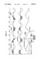
- FIG. 3is a timing diagram showing waveforms of A.C. excitation for components of the converter and registration with a sequence of sampling intervals of the converter.
- FIG. 1shows a schematic drawing of a converter 10 of analog voltage to digital count.
- the converter 10comprises an integrator 12, a comparator 14 connected to an output terminal of the integrator 12 at line 16, and a switch 18 which connects an input terminal of the integrator 12 at line 20 to a source 22 of input signal.
- An output terminal of the comparator 14, at line 24,connects with a system timing unit 26.
- the timing unit 26is operative with a microprocessor 28 coupled thereto.
- the input signal source 22is shown as test equipment for biological testing.
- a biological sample 30, indicated in phantom,has internal resistance represented by a resistor 32 through which an electric current can be impressed by a battery 34.
- the battery 34is connected serially with the resistor 32 by a current measuring resistor 36 having much smaller resistance than the resistance of the resistor 32 so as to have no more than insignificant effect on the magnitude of current flowing through the resistor 32.
- a voltage drop across the resistor 36 between terminal 38 and groundserves as a measure of the current flowing through the biological sample 30, and also serves as the input signal to the converter 10.
- the integrator 12comprises an operational amplifier 40 with a capacitor 42 connected in a feedback path between an output terminal of the amplifier 40, at line 16, and an inverting input terminal 44 of the amplifier 40.
- the electric power for operation of the amplifier 40is provided by a pair of terminals 46 and 48 which connect with terminals 50 and 52, respectively, of a D.C. power supply 54.
- the power supply 54is energized with alternating current and voltage from an A.C. power source 56.
- the power supply 54may be a regulated power supply which converts A.C. voltage to D.C. voltage.
- the A.C. voltagemay operate, by way of example, at one of the frequencies commonly used for the transmission of A.C.
- the comparator 14which may also be constructed in the form of an operational amplifier, includes terminals 58 and 60 connected respectively to the terminals 50 and 52 of the power supply 54 to receive electric power for operation of the comparator 14.
- the switch 18is a three-position selector switch electronically actuated by a signal on line 62 from the timing unit 26. In the center position, as shown, a movable contact 64 connects the input signal source 22 to the input terminal of the integrator 12 at line 20. The input signal at line 20 is applied via an input resistor 66 to the inverting input terminal 44 of the amplifier 40. There are two other positions for the switch contact 64, namely, the terminal of a calibration reference voltage source 68 and a ground terminal 70.
- the switch 18has been portrayed as a mechanical switch for simplicity of description; however, it is to be understood that in a preferred embodiment of the invention, the switch 18 is to be fabricated as an electronic switch.
- the converter 10receives an input signal sample upon a switching of the switch contact 64 from the ground terminal 70 to the input signal at terminal 38.
- the contact 64returns to the ground terminal 70.
- the signal sampleis applied via the resistor 66 to the amplifier 40 with the result that the signal sample is integrated by the capacitor 42 to provide an integrated form of the signal sample at line 16.
- the ground voltageis treated by the integrator 12 as a further input signal which is integrated. This results in a reduction of the charge stored in the capacitor 42, a discharge of the capacitor 42 which occurs at a substantially linear rate.
- the output voltage of the integrator 12 on line 16rises and falls periodically for the case of a constant voltage at the input signal. This is depicted in the third trace of the graph of FIG. 3.
- the time required to discharge the capacitor 42 to reduce the output integrator voltage to a value equal to the reference voltage of the comparator 14is directly proportional to the amplitude of the input signal of the source 22. It is noted that all sampling intervals are of equal length to ensure the proportional relationship of stored charge in the capacitor 42 to input signal amplitude.
- an accurate measurement of input signal amplitudeis made by measuring the time required to discharge the capacitor 42 a sufficient amount to bring the integrator output voltage to a level equal to that of the comparator reference signal.
- the inverting input terminal of the comparator 14is connected to ground to serve as a reference input voltage; however, the inverting input terminal could be connected to some other magnitude of reference voltage if desired.
- the connection of the non-inverting input terminal of the amplifier 40 to groundcould, if desired, be altered to provide for connection to some other magnitude of voltage reference.
- a counter 72 in the timing unit 26counts clock pulses for the duration of the foregoing discharge time of the capacitor 42.
- the foregoing discharge intervalis identified in FIG. 3 as the reference integration, while the integration of the signal sample is identified as the signal integration in FIG. 3.
- An output count of the counter 72 on line 74is proportional to the input signal at terminal 38 and, therefore, serves as a measure of the input signal at terminal 38.
- Clock pulses from a clock 76(FIG. 2) are applied via a logic unit 78 to the counter 72.
- the logic unit 78is responsive to a timing signal of the microprocessor 28 for initiating a counting by the counter 72, and is responsive furthermore to an output signal of the comparator 14 provided upon the attainment of an equality between the output voltage of the integrator 12 and the comparator reference voltage. In response to a strobing of the logic unit 78 by the comparator 14, the logic unit 78 terminates the flow of clock pulses to the counter 72 so that the count of the counter 72 is a correct measure of the reference integration time and of the input signal voltage of the source 22.
- the system timing unit 26further comprises two latches 80 and 82, three counters 84, 86 and 88, and an output bus driver 90.
- the microprocessor 28down loads into the latch 80 the duration of the signal sampling interval which, by way of example, is shown as 8 milliseconds (ms). in the third trace of FIG. 3.
- the remaining time until initiation of the next samplingis 17 ms to give a total duration of 25 ms to the composite sampling interval.
- the composite sampling intervalis equal to the sum of the sampling time, the maximum amount of time allowed for the reference integration, and time for resetting the integrator 12 by allowing the input terminal of the integrator 12 to remain at zero volts.
- the maximum allowable time for the sum of the reference integration and zero integration (reset) intervalsis 17 ms. If desired, the signal integration time can be increased to 8.33 ms, this being the length of 1/2-cycle of 60 Hertz excitation, in which case the maximum allowable time for the reference integration and zero integration would be 16.67 ms.
- the maximum allowable time for the reference integrationis loaded by the microprocessor 28 into the latch 82.
- the counter 86counts the duration of time elapsing during each of the foregoing intervals, namely the signal integration time, the maximum allowable reference integration time along with the reset interval time. To accomplish the timing of the signal integration, the integration time is down loaded from the latch 80 into the counter 86 which then counts down to zero, whereupon the counter 86 outputs a pulse signal to designate the end of the signal integration interval.
- the counter 86operates by counting clock pulses applied by the clock 76 via the logic unit 78, the clock pulses being divided by 16 at counter 84, to the counter 86.
- the maximum allowable duration of the reference integration intervalis established by down loading the length of the interval from the latch 82 to the counter 86. The counter 86 then counts down to zero whereupon comparator 14 changes state, and reset is initiated for the remainder of the interval.
- FIG. 3Upon inspection of FIG. 3, it is noted that there is a succession of four integration cycles depicted in the third trace. This provides for establishing a sequence of four measurements of the output voltage of the source 22, and an averaging of the four measurements.
- the counter 88is employed to count the successive occurrences of the sequence of four measurement intervals and the corresponding four integration cycles.
- the four cyclesare presented by way of example. If desired, integration can be accomplished over a sequence of eight measurement cycles, in which case the counter 88 is employed to count the eight cycles.
- the logic unit 78is responsive to counts of the counter 88 to cycle through the sequence of four integration cycles.
- the logic unitfirst down loads the signal integrate time to the counter 86.
- the counter 86signals the logic unit 88 to down load the reference integration time into the counter 86.
- the reset intervalis imposed. Thereupon, the count of the counter 88 is incremented to indicate completion of one of the integration cycles depicted in the third trace of FIG. 3.
- the logic unit 78places the switch contact 64 to the output terminal 38 of the source 22 and, subsequently, at the inception of the reference integration interval, places the switch contact 64 at the ground terminal 70 as has been described hereinabove. Also, as has been noted hereinabove, the logic unit 78 activates the counter 72 at the beginning of the reference integration interval to measure the discharge time.
- Output values of the digital signals provided by the counter 86, the logic unit 78, and the counter 72,are coupled via tri-state bus buffers of the driver 90 to the microprocessor 28 for the logging in of data.
- a convenience in the averaging of the signal amplitudes obtained during the sequence of four measurement intervalsis obtained by use of the counter 72 in the following manner. Upon the completion of the counting of the capacitor discharge time during the first of the four integration cycles, the count in the counter 72 is retained. Thereupon, during the next integration cycle, the next measurement count is added to the previously stored count. This procedure continues throughout the sequence of the four integration cycles to provide a total count at the conclusion of the four integration cycles. This count is proportional to the average value of four measurements of the input signal voltage obtained during the sequence of four measurements.
- the logic unit 78directs the outputting of the count from the counter 72 to the microprocessor 28, this being following by a resetting of the counter 72 to zero.
- counter 72may be preloaded from the microprocessor 28 where the preload represents a system offset correction.
- the theory of operation of the inventionis explained with reference to the three traces of FIG. 3.
- the upper traceshows the waveform of a 50 Hertz alternating current reduced by the A.C. source 56 (FIG. 1).
- the second traceshows the waveform of a 60 Hertz alternating current which may be produced, alternatively, by the A.C. source 56.
- the two waveformsare commensurate over a common interval of 100 ms, indicated on the time axis at the top of FIG. 3. During this common interval of time, there is produced an integral number of cycles of the 50 Hertz waveform and an integral number of cycles of the 60 Hertz waveform. There are five full cycles of the 50 Hertz waveform and six full cycles of the 60 Hertz waveform during this common measurement interval.
- This common measurement intervalis the basic interval during which measurements are made by the converter 10 of the invention, this interval being equal to the length of time of the four integration cycles depicted in the third trace of FIG. 3.
- shaded regions in the two upper tracescorrespond to the signal integration intervals of the third trace.
- the shaded regionare drawn in temporal registration with the signal integration intervals.
- an averaging of the four shaded regionsproduces a net value of zero.
- an averaging of the four shaded regionstwo of which are positive and two of which are negative, produces a net value of zero. Therefore, it is concluded that deviations in the measurement of the input signal voltage are essentially compensated or cancelled by the foregoing timing of the measurements and the averaging of the measurements. This cancellation applies also to harmonics of 50 and 60 Hertz.
- the shaded regions of the 60 Hertz waveformbegin at zero-crossings of every third half-cycle of the waveform.
- the first shaded regionbegins at the zero crossing
- the second shaded regionbegins at one quarter cycle beyond the zero crossing
- the third shaded regionbegins at the zero crossing but extending in the negative direction
- the fourth shaded regionbegins one quarter cycle after a zero crossing, also in the negative direction.
- the signal integration intervalsare synchronized to begin at zero crossings of the 60 Hertz, or highest frequency, waveform, and because of the use of the common measurement interval of the integral number of cycles of the two A.C. waveforms. It is noted also that the signal integration interval may be equal to, less than, or somewhat larger than one half cycle of the higher frequency waveform and still produce the foregoing cancellation effect. Of course, if the signal integration interval is excessively long, little time remains for measuring the length of the capacitor discharge time. Also, it is noted that the integration cycles of the third trace need not be synchronized with the 60 Hertz wave form, but must have the same periodicity to allow for the proper averaging.
Landscapes
- Engineering & Computer Science (AREA)
- Theoretical Computer Science (AREA)
- Analogue/Digital Conversion (AREA)
- Measurement Of Resistance Or Impedance (AREA)
- Measurement Of Current Or Voltage (AREA)
Abstract
Description
Claims (2)
Priority Applications (8)
| Application Number | Priority Date | Filing Date | Title |
|---|---|---|---|
| US07/451,212US4999632A (en) | 1989-12-15 | 1989-12-15 | Analog to digital conversion with noise reduction |
| DE69031498TDE69031498T2 (en) | 1989-12-15 | 1990-12-14 | ANALOG-DIGITAL CONVERSION WITH NOISE REDUCTION |
| JP3502860AJP2793910B2 (en) | 1989-12-15 | 1990-12-14 | Analog / digital converter with noise reduction effect |
| CA002068215ACA2068215C (en) | 1989-12-15 | 1990-12-14 | Analog to digital conversion with noise reduction |
| EP91902620AEP0505496B1 (en) | 1989-12-15 | 1990-12-14 | Analog to digital conversion with noise reduction |
| AT91902620TATE158680T1 (en) | 1989-12-15 | 1990-12-14 | ANALOG-DIGITAL CONVERSION WITH NOISE REDUCTION |
| PCT/US1990/007503WO1991009470A1 (en) | 1989-12-15 | 1990-12-14 | Analog to digital conversion with noise reduction |
| ES91902620TES2107453T3 (en) | 1989-12-15 | 1990-12-14 | ANALOG CONVERSION TO DIGITAL WITH NOISE REDUCTION. |
Applications Claiming Priority (1)
| Application Number | Priority Date | Filing Date | Title |
|---|---|---|---|
| US07/451,212US4999632A (en) | 1989-12-15 | 1989-12-15 | Analog to digital conversion with noise reduction |
Publications (1)
| Publication Number | Publication Date |
|---|---|
| US4999632Atrue US4999632A (en) | 1991-03-12 |
Family
ID=23791259
Family Applications (1)
| Application Number | Title | Priority Date | Filing Date |
|---|---|---|---|
| US07/451,212Expired - LifetimeUS4999632A (en) | 1989-12-15 | 1989-12-15 | Analog to digital conversion with noise reduction |
Country Status (8)
| Country | Link |
|---|---|
| US (1) | US4999632A (en) |
| EP (1) | EP0505496B1 (en) |
| JP (1) | JP2793910B2 (en) |
| AT (1) | ATE158680T1 (en) |
| CA (1) | CA2068215C (en) |
| DE (1) | DE69031498T2 (en) |
| ES (1) | ES2107453T3 (en) |
| WO (1) | WO1991009470A1 (en) |
Cited By (70)
| Publication number | Priority date | Publication date | Assignee | Title |
|---|---|---|---|---|
| US5144307A (en)* | 1990-06-28 | 1992-09-01 | Ando Electric Co., Ltd. | Method of controlling double integral A-D converter |
| US5274375A (en)* | 1992-04-17 | 1993-12-28 | Crystal Semiconductor Corporation | Delta-sigma modulator for an analog-to-digital converter with low thermal noise performance |
| US5373292A (en)* | 1992-07-29 | 1994-12-13 | Kabushiki Kaisha Toshiba | Integration type D-A/A-D Conversion apparatus capable of shortening conversion processing time |
| WO1994029731A1 (en)* | 1993-06-03 | 1994-12-22 | Boehringer Mannheim Corporation | Biosensor for hematocrit determination |
| US5719572A (en)* | 1994-07-08 | 1998-02-17 | Cirrus Logic, Inc. | Digital signal processor with reduced pattern dependent noise |
| US5801652A (en)* | 1994-07-08 | 1998-09-01 | Cirrus Logic, Inc. | Pattern dependent noise reduction in a digital processing circuit utilizing image circuitry |
| RU2122258C1 (en)* | 1997-02-28 | 1998-11-20 | Московский государственный институт электронной техники (технический университет) | Magnetic-field vector sensor |
| US5997817A (en)* | 1997-12-05 | 1999-12-07 | Roche Diagnostics Corporation | Electrochemical biosensor test strip |
| US6245215B1 (en) | 1998-09-30 | 2001-06-12 | Amira Medical | Membrane based electrochemical test device and related methods |
| US6262264B1 (en) | 1998-06-01 | 2001-07-17 | Roche Diagnostics Corporation | Redox reversible imidazole osmium complex conjugates |
| US6413395B1 (en) | 1999-12-16 | 2002-07-02 | Roche Diagnostics Corporation | Biosensor apparatus |
| US6428664B1 (en) | 2000-06-19 | 2002-08-06 | Roche Diagnostics Corporation | Biosensor |
| US6447657B1 (en) | 2000-12-04 | 2002-09-10 | Roche Diagnostics Corporation | Biosensor |
| US6488828B1 (en) | 2000-07-20 | 2002-12-03 | Roche Diagnostics Corporation | Recloseable biosensor |
| US6540890B1 (en) | 2000-11-01 | 2003-04-01 | Roche Diagnostics Corporation | Biosensor |
| US20030064525A1 (en)* | 1997-12-22 | 2003-04-03 | Liess Martin Dieter | Meter |
| RU2204144C2 (en)* | 2001-04-23 | 2003-05-10 | Таганрогский государственный радиотехнический университет | Integrated bipolar magnetotransistor |
| US20030096420A1 (en)* | 2001-11-07 | 2003-05-22 | Heller Zindel Herbert | Instrument |
| US6635167B1 (en) | 1997-12-04 | 2003-10-21 | Roche Diagnostics Corporation | Apparatus and method for determining the concentration of a component of a sample |
| US6645359B1 (en) | 2000-10-06 | 2003-11-11 | Roche Diagnostics Corporation | Biosensor |
| WO2003094099A1 (en)* | 2002-04-29 | 2003-11-13 | Idex Asa | System and method for measuring characteristics of a surface |
| US6755949B1 (en) | 2001-10-09 | 2004-06-29 | Roche Diagnostics Corporation | Biosensor |
| US20040138588A1 (en)* | 2002-11-06 | 2004-07-15 | Saikley Charles R | Automatic biological analyte testing meter with integrated lancing device and methods of use |
| US6767440B1 (en) | 2001-04-24 | 2004-07-27 | Roche Diagnostics Corporation | Biosensor |
| US20040157337A1 (en)* | 1997-12-22 | 2004-08-12 | Burke David W. | System and method for analyte measurement using AC phase angle measurements |
| US20040157339A1 (en)* | 1997-12-22 | 2004-08-12 | Burke David W. | System and method for analyte measurement using AC excitation |
| US6814843B1 (en) | 2000-11-01 | 2004-11-09 | Roche Diagnostics Corporation | Biosensor |
| US6814844B2 (en) | 2001-08-29 | 2004-11-09 | Roche Diagnostics Corporation | Biosensor with code pattern |
| US20040259180A1 (en)* | 2003-06-20 | 2004-12-23 | Burke David W. | System and method for analyte measurement employing maximum dosing time delay |
| US20040256248A1 (en)* | 2003-06-20 | 2004-12-23 | Burke David W. | System and method for analyte measurement using dose sufficiency electrodes |
| US20050016846A1 (en)* | 2003-06-20 | 2005-01-27 | Henning Groll | System and method for coding information on a biosensor test strip |
| US20050019945A1 (en)* | 2003-06-20 | 2005-01-27 | Henning Groll | System and method for coding information on a biosensor test strip |
| US20050211572A1 (en)* | 1999-09-20 | 2005-09-29 | Buck Harvey B | Electrochemical sensor and method for continuous analyte monitoring |
| WO2005112268A1 (en)* | 2004-05-07 | 2005-11-24 | Endress+Hauser Wetzer Gmbh+Co. Kg | Device for the analog/digital conversion of a measuring voltage |
| US20050270198A1 (en)* | 2004-05-27 | 2005-12-08 | Atmel Germany Gmbh | Circuit for current measurement and current monitoring |
| US20050284758A1 (en)* | 2004-06-18 | 2005-12-29 | Tom Funke | Novel electrode design for biosensor |
| US20060289497A1 (en)* | 2005-05-16 | 2006-12-28 | Ralph Ellerker (1795) Ltd. | Door closure system |
| US20080023327A1 (en)* | 2004-02-23 | 2008-01-31 | Mysticmd Inc. | Strip electrode with conductive nano tube printing |
| US7338639B2 (en) | 1997-12-22 | 2008-03-04 | Roche Diagnostics Operations, Inc. | System and method for analyte measurement |
| US20080243032A1 (en)* | 2005-10-20 | 2008-10-02 | Fritz Hindelang | Analytical device including sterile protection |
| US7473398B2 (en) | 2001-05-25 | 2009-01-06 | Roche Diagnostics Operations, Inc. | Biosensor |
| US7488601B2 (en) | 2003-06-20 | 2009-02-10 | Roche Diagnostic Operations, Inc. | System and method for determining an abused sensor during analyte measurement |
| US7569126B2 (en) | 2004-06-18 | 2009-08-04 | Roche Diagnostics Operations, Inc. | System and method for quality assurance of a biosensor test strip |
| US7604721B2 (en) | 2003-06-20 | 2009-10-20 | Roche Diagnostics Operations, Inc. | System and method for coding information on a biosensor test strip |
| US20090278720A1 (en)* | 2008-05-07 | 2009-11-12 | Schneider Edmund M | Delta-sigma analog-to-digital converter circuit having reduced sampled reference noise |
| US7645421B2 (en) | 2003-06-20 | 2010-01-12 | Roche Diagnostics Operations, Inc. | System and method for coding information on a biosensor test strip |
| US7718439B2 (en) | 2003-06-20 | 2010-05-18 | Roche Diagnostics Operations, Inc. | System and method for coding information on a biosensor test strip |
| US20100170807A1 (en)* | 2003-06-20 | 2010-07-08 | Diebold Eric R | System and method for determining the concentration of an analyte in a sample fluid |
| US8009077B1 (en) | 2009-06-08 | 2011-08-30 | Cirrus Logic, Inc. | Delta-sigma analog-to-digital converter (ADC) circuit with selectively switched reference |
| US8071384B2 (en) | 1997-12-22 | 2011-12-06 | Roche Diagnostics Operations, Inc. | Control and calibration solutions and methods for their use |
| EP2465862A1 (en) | 2003-07-01 | 2012-06-20 | Roche Diagniostics GmbH | Mononuclear osmium complexes for use in biosensors |
| US8206565B2 (en) | 2003-06-20 | 2012-06-26 | Roche Diagnostics Operation, Inc. | System and method for coding information on a biosensor test strip |
| US20120218020A1 (en)* | 2011-02-25 | 2012-08-30 | Maxim Integrated Products, Inc. | Calibration for mixed-signal integrator architecture |
| US8404100B2 (en) | 2005-09-30 | 2013-03-26 | Bayer Healthcare Llc | Gated voltammetry |
| US8425757B2 (en) | 2005-07-20 | 2013-04-23 | Bayer Healthcare Llc | Gated amperometry |
| WO2014062985A1 (en) | 2012-10-17 | 2014-04-24 | University Of Maryland, Office Of Technology Commercialization | Device and methods of using device for detection of aminoacidopathies |
| WO2014140170A1 (en) | 2013-03-15 | 2014-09-18 | Roche Diagnostics Gmbh | Methods of scaling data used to construct biosensor algorithms as well as devices, apparatuses and systems incorporating the same |
| WO2014140164A1 (en) | 2013-03-15 | 2014-09-18 | Roche Diagnostics Gmbh | Methods of using information from recovery pulses in electrochemical analyte measurements as well as devices, apparatuses and systems incorporating the same |
| WO2014140177A2 (en) | 2013-03-15 | 2014-09-18 | Roche Diagnostics Gmbh | Methods of detecting high antioxidant levels during electrochemical measurements and failsafing an analyte concentration therefrom as well as devices, apparatuses and systems incorporting the same |
| WO2014140172A1 (en) | 2013-03-15 | 2014-09-18 | Roche Diagnostics Gmbh | Methods of failsafing electrochemical measurements of an analyte as well as devices, apparatuses and systems incorporating the same |
| WO2015161301A1 (en) | 2014-04-17 | 2015-10-22 | University Of Maryland, College Park | Device and methods of using device for detection of aminoacidopathies |
| US9410917B2 (en) | 2004-02-06 | 2016-08-09 | Ascensia Diabetes Care Holdings Ag | Method of using a biosensor |
| WO2016176366A1 (en) | 2015-04-27 | 2016-11-03 | University Of Maryland, College Park | Device and methods of using device for detection of hyperammonemia |
| US9552102B2 (en) | 2011-02-25 | 2017-01-24 | Qualcomm Incorporated | Background noise measurement and frequency selection in touch panel sensor systems |
| US9846186B2 (en) | 2011-02-25 | 2017-12-19 | Qualcomm Incorporated | Capacitive touch sense architecture having a correlator for demodulating a measured capacitance from an excitation signal |
| US9933385B2 (en) | 2007-12-10 | 2018-04-03 | Ascensia Diabetes Care Holdings Ag | Method of using an electrochemical test sensor |
| WO2018067235A1 (en) | 2016-10-05 | 2018-04-12 | Roche Diabetes Care, Inc. | Detection reagents and electrode arrangements for multi-analyte diagnostic test elements, as well as methods of using the same |
| US9952199B2 (en) | 2013-08-30 | 2018-04-24 | University Of Maryland, College Park | Device and methods of using device for detection of hyperammonemia |
| EP4033235A1 (en) | 2014-11-03 | 2022-07-27 | Roche Diabetes Care GmbH | Methods of use of electrode arrangements for electrochemical test elements |
| US12345672B2 (en) | 2016-10-24 | 2025-07-01 | Roche Diabetes Care, Inc. | Methods of correcting for uncompensated resistances in the conductive elements of biosensors, as well as devices and systems incorporating the same |
Families Citing this family (1)
| Publication number | Priority date | Publication date | Assignee | Title |
|---|---|---|---|---|
| CN111537875B (en)* | 2020-06-01 | 2021-03-05 | 泉州睿郎机电技术有限公司 | Method and device for collecting and measuring switching time of double-power-supply change-over switch contact |
Citations (6)
| Publication number | Priority date | Publication date | Assignee | Title |
|---|---|---|---|---|
| US3696403A (en)* | 1970-11-25 | 1972-10-03 | Gordon Eng Co | Low level conversion system |
| US3701146A (en)* | 1969-12-08 | 1972-10-24 | Iwatsu Electric Co Ltd | Analog-digital converter using an integrator |
| US3729733A (en)* | 1970-11-24 | 1973-04-24 | Solartron Electronic Group | Analogue to digital converters |
| US4633221A (en)* | 1983-10-24 | 1986-12-30 | Intersil, Inc. | Dual slope analog-to-digital converter with automatic, short cycle range determination |
| US4656459A (en)* | 1985-10-07 | 1987-04-07 | Intersil, Inc. | Dual slope converter with large apparent integrator swing |
| US4908623A (en)* | 1988-08-08 | 1990-03-13 | Honeywell Inc. | Apparatus and method for range control and supply voltage compensation in a dual slope analog to digital converter |
- 1989
- 1989-12-15USUS07/451,212patent/US4999632A/ennot_activeExpired - Lifetime
- 1990
- 1990-12-14WOPCT/US1990/007503patent/WO1991009470A1/enactiveIP Right Grant
- 1990-12-14EPEP91902620Apatent/EP0505496B1/ennot_activeExpired - Lifetime
- 1990-12-14ESES91902620Tpatent/ES2107453T3/ennot_activeExpired - Lifetime
- 1990-12-14ATAT91902620Tpatent/ATE158680T1/enactive
- 1990-12-14DEDE69031498Tpatent/DE69031498T2/ennot_activeExpired - Lifetime
- 1990-12-14CACA002068215Apatent/CA2068215C/ennot_activeExpired - Lifetime
- 1990-12-14JPJP3502860Apatent/JP2793910B2/ennot_activeExpired - Lifetime
Patent Citations (6)
| Publication number | Priority date | Publication date | Assignee | Title |
|---|---|---|---|---|
| US3701146A (en)* | 1969-12-08 | 1972-10-24 | Iwatsu Electric Co Ltd | Analog-digital converter using an integrator |
| US3729733A (en)* | 1970-11-24 | 1973-04-24 | Solartron Electronic Group | Analogue to digital converters |
| US3696403A (en)* | 1970-11-25 | 1972-10-03 | Gordon Eng Co | Low level conversion system |
| US4633221A (en)* | 1983-10-24 | 1986-12-30 | Intersil, Inc. | Dual slope analog-to-digital converter with automatic, short cycle range determination |
| US4656459A (en)* | 1985-10-07 | 1987-04-07 | Intersil, Inc. | Dual slope converter with large apparent integrator swing |
| US4908623A (en)* | 1988-08-08 | 1990-03-13 | Honeywell Inc. | Apparatus and method for range control and supply voltage compensation in a dual slope analog to digital converter |
Cited By (160)
| Publication number | Priority date | Publication date | Assignee | Title |
|---|---|---|---|---|
| US5144307A (en)* | 1990-06-28 | 1992-09-01 | Ando Electric Co., Ltd. | Method of controlling double integral A-D converter |
| US5274375A (en)* | 1992-04-17 | 1993-12-28 | Crystal Semiconductor Corporation | Delta-sigma modulator for an analog-to-digital converter with low thermal noise performance |
| US5373292A (en)* | 1992-07-29 | 1994-12-13 | Kabushiki Kaisha Toshiba | Integration type D-A/A-D Conversion apparatus capable of shortening conversion processing time |
| WO1994029731A1 (en)* | 1993-06-03 | 1994-12-22 | Boehringer Mannheim Corporation | Biosensor for hematocrit determination |
| US5385846A (en)* | 1993-06-03 | 1995-01-31 | Boehringer Mannheim Corporation | Biosensor and method for hematocrit determination |
| US5719572A (en)* | 1994-07-08 | 1998-02-17 | Cirrus Logic, Inc. | Digital signal processor with reduced pattern dependent noise |
| US5801652A (en)* | 1994-07-08 | 1998-09-01 | Cirrus Logic, Inc. | Pattern dependent noise reduction in a digital processing circuit utilizing image circuitry |
| RU2122258C1 (en)* | 1997-02-28 | 1998-11-20 | Московский государственный институт электронной техники (технический университет) | Magnetic-field vector sensor |
| US6582573B2 (en) | 1997-09-30 | 2003-06-24 | Amira Medical | Membrane based electrochemical test device |
| EP2270481A1 (en) | 1997-12-04 | 2011-01-05 | Roche Diagnostics Operations, Inc. | Glucose measuring instrument |
| US6635167B1 (en) | 1997-12-04 | 2003-10-21 | Roche Diagnostics Corporation | Apparatus and method for determining the concentration of a component of a sample |
| US5997817A (en)* | 1997-12-05 | 1999-12-07 | Roche Diagnostics Corporation | Electrochemical biosensor test strip |
| USRE42560E1 (en) | 1997-12-05 | 2011-07-19 | Roche Diagnostics Operations, Inc. | Electrochemical biosensor test strip |
| USRE42924E1 (en) | 1997-12-05 | 2011-11-15 | Roche Diagnostics Operations, Inc. | Electrochemical biosensor test strip |
| USRE43815E1 (en) | 1997-12-05 | 2012-11-20 | Roche Diagnostics Operations, Inc. | Electrochemical biosensor test strip |
| USRE42953E1 (en) | 1997-12-05 | 2011-11-22 | Roche Diagnostics Operations, Inc. | Electrochemical biosensor test strip |
| USRE41309E1 (en) | 1997-12-05 | 2010-05-04 | Roche Diagnostics Operations, Inc. | Electrochemical biosensor test strip |
| US7390667B2 (en) | 1997-12-22 | 2008-06-24 | Roche Diagnostics Operations, Inc. | System and method for analyte measurement using AC phase angle measurements |
| US7494816B2 (en) | 1997-12-22 | 2009-02-24 | Roche Diagnostic Operations, Inc. | System and method for determining a temperature during analyte measurement |
| EP2085779A1 (en) | 1997-12-22 | 2009-08-05 | Roche Diagnostics Operations, Inc. | Meter |
| EP2085778A1 (en) | 1997-12-22 | 2009-08-05 | Roche Diagnostics Operations, Inc. | Meter |
| US8071384B2 (en) | 1997-12-22 | 2011-12-06 | Roche Diagnostics Operations, Inc. | Control and calibration solutions and methods for their use |
| US20030064525A1 (en)* | 1997-12-22 | 2003-04-03 | Liess Martin Dieter | Meter |
| US7338639B2 (en) | 1997-12-22 | 2008-03-04 | Roche Diagnostics Operations, Inc. | System and method for analyte measurement |
| US20040157339A1 (en)* | 1997-12-22 | 2004-08-12 | Burke David W. | System and method for analyte measurement using AC excitation |
| US20040157337A1 (en)* | 1997-12-22 | 2004-08-12 | Burke David W. | System and method for analyte measurement using AC phase angle measurements |
| US7407811B2 (en) | 1997-12-22 | 2008-08-05 | Roche Diagnostics Operations, Inc. | System and method for analyte measurement using AC excitation |
| US20040005716A9 (en)* | 1997-12-22 | 2004-01-08 | Beaty Terry A. | Meter |
| US20020090632A1 (en)* | 1998-06-01 | 2002-07-11 | Buck Harvey B. | Redox reversible bipyridyl-osmium complex conjugates |
| US6352824B1 (en) | 1998-06-01 | 2002-03-05 | Roche Diagnostics Corporation | Redox reversible bipyridyl-osmium complex conjugates |
| US7045310B2 (en) | 1998-06-01 | 2006-05-16 | Roche Diagnostics Operations, Inc. | Redox reversible bipyridyl-osmium complex conjugates |
| USRE40198E1 (en) | 1998-06-01 | 2008-04-01 | Roche Diagnostics Operations, Inc. | Method and device for electrochemical immunoassay of multiple analytes |
| US6294062B1 (en) | 1998-06-01 | 2001-09-25 | Roche Diagnostics Corporation | Method and device for electrochemical immunoassay of multiple analytes |
| US6262264B1 (en) | 1998-06-01 | 2001-07-17 | Roche Diagnostics Corporation | Redox reversible imidazole osmium complex conjugates |
| US6245215B1 (en) | 1998-09-30 | 2001-06-12 | Amira Medical | Membrane based electrochemical test device and related methods |
| US20050211572A1 (en)* | 1999-09-20 | 2005-09-29 | Buck Harvey B | Electrochemical sensor and method for continuous analyte monitoring |
| US7045054B1 (en) | 1999-09-20 | 2006-05-16 | Roche Diagnostics Corporation | Small volume biosensor for continuous analyte monitoring |
| US7731835B2 (en) | 1999-09-20 | 2010-06-08 | Roche Diagnostics Operations, Inc. | Electrochemical sensor and method for continuous analyte monitoring |
| US6413395B1 (en) | 1999-12-16 | 2002-07-02 | Roche Diagnostics Corporation | Biosensor apparatus |
| US6428664B1 (en) | 2000-06-19 | 2002-08-06 | Roche Diagnostics Corporation | Biosensor |
| US7063774B2 (en) | 2000-07-20 | 2006-06-20 | Roche Diagnostics Operations, Inc. | Recloseable biosensor |
| US20030047451A1 (en)* | 2000-07-20 | 2003-03-13 | Bhullar Raghbir Singh | Recloseable biosensor |
| US6488828B1 (en) | 2000-07-20 | 2002-12-03 | Roche Diagnostics Corporation | Recloseable biosensor |
| US7287318B2 (en) | 2000-10-06 | 2007-10-30 | Roche Diagnostics Operations, Inc. | Biosensor |
| US6645359B1 (en) | 2000-10-06 | 2003-11-11 | Roche Diagnostics Corporation | Biosensor |
| US20040163953A1 (en)* | 2000-10-06 | 2004-08-26 | Bhullar Raghbir S. | Biosensor |
| US6814843B1 (en) | 2000-11-01 | 2004-11-09 | Roche Diagnostics Corporation | Biosensor |
| US20030094367A1 (en)* | 2000-11-01 | 2003-05-22 | Bhullar Raghbir S. | Biosensor |
| EP2280277A1 (en) | 2000-11-01 | 2011-02-02 | Roche Diagnostics GmbH | Biosensor with flow channel |
| US6911621B2 (en) | 2000-11-01 | 2005-06-28 | Roche Diagnostics Corporation | Biosensor |
| US6540890B1 (en) | 2000-11-01 | 2003-04-01 | Roche Diagnostics Corporation | Biosensor |
| US6447657B1 (en) | 2000-12-04 | 2002-09-10 | Roche Diagnostics Corporation | Biosensor |
| EP2824188A1 (en) | 2000-12-04 | 2015-01-14 | Roche Diagniostics GmbH | Biosensor |
| RU2204144C2 (en)* | 2001-04-23 | 2003-05-10 | Таганрогский государственный радиотехнический университет | Integrated bipolar magnetotransistor |
| US20040206625A1 (en)* | 2001-04-24 | 2004-10-21 | Bhullar Raghbir S. | Biosensor |
| US7479211B2 (en) | 2001-04-24 | 2009-01-20 | Roche Diagnostics Operations, Inc. | Biosensor |
| US6767440B1 (en) | 2001-04-24 | 2004-07-27 | Roche Diagnostics Corporation | Biosensor |
| US7473398B2 (en) | 2001-05-25 | 2009-01-06 | Roche Diagnostics Operations, Inc. | Biosensor |
| US7476827B1 (en) | 2001-08-29 | 2009-01-13 | Roche Diagnostics Operations, Inc. | Method of making a biosensor |
| US7780827B1 (en) | 2001-08-29 | 2010-08-24 | Roche Diagnostics Operations, Inc. | Biosensor |
| US6814844B2 (en) | 2001-08-29 | 2004-11-09 | Roche Diagnostics Corporation | Biosensor with code pattern |
| US20100219071A1 (en)* | 2001-08-29 | 2010-09-02 | Bhullar Raghbir S | Biosensor |
| US20080314882A1 (en)* | 2001-08-29 | 2008-12-25 | Bhullar Raghbir S | Method of making a biosensor |
| US6755949B1 (en) | 2001-10-09 | 2004-06-29 | Roche Diagnostics Corporation | Biosensor |
| US20080293082A1 (en)* | 2001-11-07 | 2008-11-27 | Zindel Herbert Heller | Instrument |
| US7923258B2 (en) | 2001-11-07 | 2011-04-12 | Roche Diagnostics Operations, Inc. | Instrument |
| US20030096420A1 (en)* | 2001-11-07 | 2003-05-22 | Heller Zindel Herbert | Instrument |
| US7927882B2 (en) | 2001-11-07 | 2011-04-19 | Roche Diagnostics Operations, Inc. | Instrument |
| US7018843B2 (en) | 2001-11-07 | 2006-03-28 | Roche Diagnostics Operations, Inc. | Instrument |
| WO2003094099A1 (en)* | 2002-04-29 | 2003-11-13 | Idex Asa | System and method for measuring characteristics of a surface |
| US20040138588A1 (en)* | 2002-11-06 | 2004-07-15 | Saikley Charles R | Automatic biological analyte testing meter with integrated lancing device and methods of use |
| US20090259147A1 (en)* | 2002-11-06 | 2009-10-15 | Abbott Diabetes Care Inc. | Automatic biological analyte testing meter with integrated lancing device and methods of use |
| US9060727B2 (en) | 2002-11-06 | 2015-06-23 | Abbott Diabetes Care Inc. | Automatic biological analyte testing meter with integrated lancing device and methods of use |
| US8079961B2 (en) | 2002-11-06 | 2011-12-20 | Abbott Diabetes Care Inc. | Automatic biological analyte testing meter with integrated lancing device and methods of use |
| US7572237B2 (en) | 2002-11-06 | 2009-08-11 | Abbott Diabetes Care Inc. | Automatic biological analyte testing meter with integrated lancing device and methods of use |
| US7645373B2 (en) | 2003-06-20 | 2010-01-12 | Roche Diagnostic Operations, Inc. | System and method for coding information on a biosensor test strip |
| US7488601B2 (en) | 2003-06-20 | 2009-02-10 | Roche Diagnostic Operations, Inc. | System and method for determining an abused sensor during analyte measurement |
| US7604721B2 (en) | 2003-06-20 | 2009-10-20 | Roche Diagnostics Operations, Inc. | System and method for coding information on a biosensor test strip |
| US7597793B2 (en) | 2003-06-20 | 2009-10-06 | Roche Operations Ltd. | System and method for analyte measurement employing maximum dosing time delay |
| US7645421B2 (en) | 2003-06-20 | 2010-01-12 | Roche Diagnostics Operations, Inc. | System and method for coding information on a biosensor test strip |
| US8586373B2 (en) | 2003-06-20 | 2013-11-19 | Roche Diagnostics Operations, Inc. | System and method for determining the concentration of an analyte in a sample fluid |
| US8507289B1 (en) | 2003-06-20 | 2013-08-13 | Roche Diagnostics Operations, Inc. | System and method for coding information on a biosensor test strip |
| US8859293B2 (en) | 2003-06-20 | 2014-10-14 | Roche Diagnostics Operations, Inc. | Method for determining whether a disposable, dry regent, electrochemical test strip is unsuitable for use |
| US20100111764A1 (en)* | 2003-06-20 | 2010-05-06 | Henning Groll | System and method for coding information on a biosensor test strip |
| US7718439B2 (en) | 2003-06-20 | 2010-05-18 | Roche Diagnostics Operations, Inc. | System and method for coding information on a biosensor test strip |
| US20090089010A1 (en)* | 2003-06-20 | 2009-04-02 | Burke David W | System and method for determining an abused sensor during analyte measurement |
| US20050016846A1 (en)* | 2003-06-20 | 2005-01-27 | Henning Groll | System and method for coding information on a biosensor test strip |
| US20100170807A1 (en)* | 2003-06-20 | 2010-07-08 | Diebold Eric R | System and method for determining the concentration of an analyte in a sample fluid |
| US20050019945A1 (en)* | 2003-06-20 | 2005-01-27 | Henning Groll | System and method for coding information on a biosensor test strip |
| US7452457B2 (en) | 2003-06-20 | 2008-11-18 | Roche Diagnostics Operations, Inc. | System and method for analyte measurement using dose sufficiency electrodes |
| US8298828B2 (en) | 2003-06-20 | 2012-10-30 | Roche Diagnostics Operations, Inc. | System and method for determining the concentration of an analyte in a sample fluid |
| US8293538B2 (en) | 2003-06-20 | 2012-10-23 | Roche Diagnostics Operations, Inc. | System and method for coding information on a biosensor test strip |
| US20040256248A1 (en)* | 2003-06-20 | 2004-12-23 | Burke David W. | System and method for analyte measurement using dose sufficiency electrodes |
| US8206565B2 (en) | 2003-06-20 | 2012-06-26 | Roche Diagnostics Operation, Inc. | System and method for coding information on a biosensor test strip |
| US7977112B2 (en)* | 2003-06-20 | 2011-07-12 | Roche Diagnostics Operations, Inc. | System and method for determining an abused sensor during analyte measurement |
| US8663442B2 (en) | 2003-06-20 | 2014-03-04 | Roche Diagnostics Operations, Inc. | System and method for analyte measurement using dose sufficiency electrodes |
| US20040259180A1 (en)* | 2003-06-20 | 2004-12-23 | Burke David W. | System and method for analyte measurement employing maximum dosing time delay |
| US8148164B2 (en) | 2003-06-20 | 2012-04-03 | Roche Diagnostics Operations, Inc. | System and method for determining the concentration of an analyte in a sample fluid |
| US8058077B2 (en) | 2003-06-20 | 2011-11-15 | Roche Diagnostics Operations, Inc. | Method for coding information on a biosensor test strip |
| US8083993B2 (en) | 2003-06-20 | 2011-12-27 | Riche Diagnostics Operations, Inc. | System and method for coding information on a biosensor test strip |
| EP2465862A1 (en) | 2003-07-01 | 2012-06-20 | Roche Diagniostics GmbH | Mononuclear osmium complexes for use in biosensors |
| US10067082B2 (en) | 2004-02-06 | 2018-09-04 | Ascensia Diabetes Care Holdings Ag | Biosensor for determining an analyte concentration |
| US9410917B2 (en) | 2004-02-06 | 2016-08-09 | Ascensia Diabetes Care Holdings Ag | Method of using a biosensor |
| US20080023327A1 (en)* | 2004-02-23 | 2008-01-31 | Mysticmd Inc. | Strip electrode with conductive nano tube printing |
| US20080258956A1 (en)* | 2004-05-07 | 2008-10-23 | Endress+ Hauser Wetzer Gmbh +Co., Kg | Apparatus for Analog/Digital Conversion of a Measurement Voltage |
| CN1981444B (en)* | 2004-05-07 | 2011-11-16 | 恩德莱斯和豪瑟尔韦泽两合公司 | Device for the analog/digital conversion of a measuring voltage |
| US7649489B2 (en) | 2004-05-07 | 2010-01-19 | Endress + Hauser Wetzer Gmbh + Co. Kg | Apparatus for analog/digital conversion of a measurement voltage |
| WO2005112268A1 (en)* | 2004-05-07 | 2005-11-24 | Endress+Hauser Wetzer Gmbh+Co. Kg | Device for the analog/digital conversion of a measuring voltage |
| US20050270198A1 (en)* | 2004-05-27 | 2005-12-08 | Atmel Germany Gmbh | Circuit for current measurement and current monitoring |
| US7075464B2 (en)* | 2004-05-27 | 2006-07-11 | Atmel Germany Gmbh | Circuit for current measurement and current monitoring |
| US9410915B2 (en) | 2004-06-18 | 2016-08-09 | Roche Operations Ltd. | System and method for quality assurance of a biosensor test strip |
| US7556723B2 (en) | 2004-06-18 | 2009-07-07 | Roche Diagnostics Operations, Inc. | Electrode design for biosensor |
| US20050284758A1 (en)* | 2004-06-18 | 2005-12-29 | Tom Funke | Novel electrode design for biosensor |
| US7569126B2 (en) | 2004-06-18 | 2009-08-04 | Roche Diagnostics Operations, Inc. | System and method for quality assurance of a biosensor test strip |
| US8092668B2 (en) | 2004-06-18 | 2012-01-10 | Roche Diagnostics Operations, Inc. | System and method for quality assurance of a biosensor test strip |
| US20060289497A1 (en)* | 2005-05-16 | 2006-12-28 | Ralph Ellerker (1795) Ltd. | Door closure system |
| US8877035B2 (en) | 2005-07-20 | 2014-11-04 | Bayer Healthcare Llc | Gated amperometry methods |
| US8425757B2 (en) | 2005-07-20 | 2013-04-23 | Bayer Healthcare Llc | Gated amperometry |
| US8647489B2 (en) | 2005-09-30 | 2014-02-11 | Bayer Healthcare Llc | Gated voltammetry devices |
| US11435312B2 (en) | 2005-09-30 | 2022-09-06 | Ascensia Diabetes Care Holdings Ag | Devices using gated voltammetry methods |
| US10670553B2 (en) | 2005-09-30 | 2020-06-02 | Ascensia Diabetes Care Holdings Ag | Devices using gated voltammetry methods |
| US8404100B2 (en) | 2005-09-30 | 2013-03-26 | Bayer Healthcare Llc | Gated voltammetry |
| US9835582B2 (en) | 2005-09-30 | 2017-12-05 | Ascensia Diabetes Care Holdings Ag | Devices using gated voltammetry methods |
| US9110013B2 (en) | 2005-09-30 | 2015-08-18 | Bayer Healthcare Llc | Gated voltammetry methods |
| US20080243032A1 (en)* | 2005-10-20 | 2008-10-02 | Fritz Hindelang | Analytical device including sterile protection |
| US10690614B2 (en) | 2007-12-10 | 2020-06-23 | Ascensia Diabetes Care Holdings Ag | Method of using an electrochemical test sensor |
| US9933385B2 (en) | 2007-12-10 | 2018-04-03 | Ascensia Diabetes Care Holdings Ag | Method of using an electrochemical test sensor |
| US20090278720A1 (en)* | 2008-05-07 | 2009-11-12 | Schneider Edmund M | Delta-sigma analog-to-digital converter circuit having reduced sampled reference noise |
| US7746257B2 (en) | 2008-05-07 | 2010-06-29 | Cirrus Logic, Inc. | Delta-sigma analog-to-digital converter circuit having reduced sampled reference noise |
| US8009077B1 (en) | 2009-06-08 | 2011-08-30 | Cirrus Logic, Inc. | Delta-sigma analog-to-digital converter (ADC) circuit with selectively switched reference |
| US9857932B2 (en) | 2011-02-25 | 2018-01-02 | Qualcomm Incorporated | Capacitive touch sense architecture having a correlator for demodulating a measured capacitance from an excitation signal |
| CN102854396B (en)* | 2011-02-25 | 2016-01-20 | 马克西姆综合产品公司 | The calibration of mixed signal integrator framework |
| US20120218020A1 (en)* | 2011-02-25 | 2012-08-30 | Maxim Integrated Products, Inc. | Calibration for mixed-signal integrator architecture |
| US9552102B2 (en) | 2011-02-25 | 2017-01-24 | Qualcomm Incorporated | Background noise measurement and frequency selection in touch panel sensor systems |
| US9625507B2 (en) | 2011-02-25 | 2017-04-18 | Qualcomm Incorporated | Continuous time correlator architecture |
| CN102854396A (en)* | 2011-02-25 | 2013-01-02 | 马克西姆综合产品公司 | Calibration for mixed-signal integrator architecture |
| US9846186B2 (en) | 2011-02-25 | 2017-12-19 | Qualcomm Incorporated | Capacitive touch sense architecture having a correlator for demodulating a measured capacitance from an excitation signal |
| US8659343B2 (en)* | 2011-02-25 | 2014-02-25 | Maxim Integrated Products, Inc. | Calibration for mixed-signal integrator architecture |
| WO2014062985A1 (en) | 2012-10-17 | 2014-04-24 | University Of Maryland, Office Of Technology Commercialization | Device and methods of using device for detection of aminoacidopathies |
| US10392646B2 (en) | 2012-10-17 | 2019-08-27 | University Of Maryland, College Park | Device and methods of using device for detection of aminoacidopathies |
| EP3385707A1 (en) | 2013-03-15 | 2018-10-10 | Roche Diabetes Care GmbH | Methods of scaling data used to construct biosensor algorithms as well as devices, apparatuses and systems incorporating the same |
| WO2014140170A1 (en) | 2013-03-15 | 2014-09-18 | Roche Diagnostics Gmbh | Methods of scaling data used to construct biosensor algorithms as well as devices, apparatuses and systems incorporating the same |
| WO2014140164A1 (en) | 2013-03-15 | 2014-09-18 | Roche Diagnostics Gmbh | Methods of using information from recovery pulses in electrochemical analyte measurements as well as devices, apparatuses and systems incorporating the same |
| WO2014140177A2 (en) | 2013-03-15 | 2014-09-18 | Roche Diagnostics Gmbh | Methods of detecting high antioxidant levels during electrochemical measurements and failsafing an analyte concentration therefrom as well as devices, apparatuses and systems incorporting the same |
| EP3385706A1 (en) | 2013-03-15 | 2018-10-10 | Roche Diabetes Care GmbH | Methods of scaling data used to construct biosensor algorithms as well as devices, apparatuses and systems incorporating the same |
| WO2014140172A1 (en) | 2013-03-15 | 2014-09-18 | Roche Diagnostics Gmbh | Methods of failsafing electrochemical measurements of an analyte as well as devices, apparatuses and systems incorporating the same |
| EP3388823A1 (en) | 2013-03-15 | 2018-10-17 | Roche Diabetes Care GmbH | Methods of scaling data used to construct biosensor algorithms as well as devices, apparatuses and systems incorporating the same |
| EP3388824A1 (en) | 2013-03-15 | 2018-10-17 | Roche Diabetes Care GmbH | Methods of detecting high antioxidant levels during electrochemical measurements and failsafing an analyte concentration therefrom as well as devices, apparatuses and systems incorporting the same |
| EP3540429A1 (en) | 2013-08-30 | 2019-09-18 | University of Maryland, College Park | Device and methods of using device for detection of hyperammonemia |
| US10620187B2 (en) | 2013-08-30 | 2020-04-14 | University Of Maryland, College Park | Device and methods of using device for detection of hyperammonemia |
| US9952199B2 (en) | 2013-08-30 | 2018-04-24 | University Of Maryland, College Park | Device and methods of using device for detection of hyperammonemia |
| WO2015161301A1 (en) | 2014-04-17 | 2015-10-22 | University Of Maryland, College Park | Device and methods of using device for detection of aminoacidopathies |
| EP4033235A1 (en) | 2014-11-03 | 2022-07-27 | Roche Diabetes Care GmbH | Methods of use of electrode arrangements for electrochemical test elements |
| WO2016176366A1 (en) | 2015-04-27 | 2016-11-03 | University Of Maryland, College Park | Device and methods of using device for detection of hyperammonemia |
| US10591495B2 (en) | 2015-04-27 | 2020-03-17 | University Of Maryland, College Park | Device and methods of using device for detection of hyperammonemia |
| WO2018067235A1 (en) | 2016-10-05 | 2018-04-12 | Roche Diabetes Care, Inc. | Detection reagents and electrode arrangements for multi-analyte diagnostic test elements, as well as methods of using the same |
| US11230727B2 (en) | 2016-10-05 | 2022-01-25 | Roche Diabetes Care, Inc. | Detection reagents and electrode arrangements for multi-analyte diagnostic test elements, as well as methods of using the same |
| US12024735B2 (en) | 2016-10-05 | 2024-07-02 | Roche Diabetes Care, Inc. | Detection reagents and electrode arrangements for multi-analyte diagnostic test elements, as well as methods of using the same |
| EP4481375A2 (en) | 2016-10-05 | 2024-12-25 | F. Hoffmann-La Roche AG | Detection reagents and electrode arrangements for multi-analyte diagnostic test elements, as well as methods of using the same |
| US12345672B2 (en) | 2016-10-24 | 2025-07-01 | Roche Diabetes Care, Inc. | Methods of correcting for uncompensated resistances in the conductive elements of biosensors, as well as devices and systems incorporating the same |
Also Published As
| Publication number | Publication date |
|---|---|
| ATE158680T1 (en) | 1997-10-15 |
| ES2107453T3 (en) | 1997-12-01 |
| WO1991009470A1 (en) | 1991-06-27 |
| CA2068215C (en) | 1999-06-01 |
| EP0505496B1 (en) | 1997-09-24 |
| EP0505496A1 (en) | 1992-09-30 |
| JP2793910B2 (en) | 1998-09-03 |
| DE69031498D1 (en) | 1997-10-30 |
| JPH05502772A (en) | 1993-05-13 |
| CA2068215A1 (en) | 1991-06-16 |
| EP0505496A4 (en) | 1994-10-26 |
| DE69031498T2 (en) | 1998-02-05 |
Similar Documents
| Publication | Publication Date | Title |
|---|---|---|
| US4999632A (en) | Analog to digital conversion with noise reduction | |
| JPH11248806A (en) | Apparatus and method for measuring charged state of battery by using coulometric analysis method | |
| JPS6166971A (en) | Method and circuit for measuring resistance of temperature detector and digitizing it | |
| JPS58105625A (en) | Multiplexed analog-to-digital converter | |
| US4437057A (en) | Frequency detection system | |
| US3981586A (en) | Continuously monitoring ratiometer | |
| SU1429948A3 (en) | Static kilowatt-hour meter | |
| US3543152A (en) | Circuit arrangement for the digital measurement of electrical magnitudes in a logarithmic scale | |
| KR0121568B1 (en) | Current/voltage test circuit in circuit tester | |
| SU1621052A1 (en) | Device for integrating electric signals with background component | |
| RU1794752C (en) | Track circuit | |
| SU1091090A1 (en) | Phase-meter | |
| SU1354136A1 (en) | Device for determining amplitude-frequency characteristics of power objects | |
| SU1552153A1 (en) | Controllable consumer of active current | |
| SU1684753A1 (en) | Method of determining the matrix plazma-panel display parameters | |
| SU674212A1 (en) | Digital meter of monopulse signals | |
| KR0129475B1 (en) | Noise-removing circuit of anglog/digital converter | |
| SU999155A1 (en) | High-frequency signal amplitude measuring device | |
| JPH0629722Y2 (en) | AE measuring device | |
| SU982647A1 (en) | Device for measuring crytical frequency of flicker confluence | |
| SU1073713A1 (en) | Linear-changing signal analog-digital converter dynamic error measuring device | |
| JPS62254069A (en) | Voltage and current detection method for power converter equipment | |
| SU1651240A1 (en) | Method for determining parameters of exponential radio and video pulses and device therefor | |
| SU902230A2 (en) | Pulse amplitude-to-dc voltage converter | |
| SU1174867A1 (en) | Method of strong d.c. |
Legal Events
| Date | Code | Title | Description |
|---|---|---|---|
| AS | Assignment | Owner name:BOEHRINGER MANNHEIM CORP., INDIANA Free format text:ASSIGNMENT OF ASSIGNORS INTEREST.;ASSIGNOR:PARKS, ROBERT A.;REEL/FRAME:005253/0322 Effective date:19900119 | |
| STCF | Information on status: patent grant | Free format text:PATENTED CASE | |
| FEPP | Fee payment procedure | Free format text:PAYOR NUMBER ASSIGNED (ORIGINAL EVENT CODE: ASPN); ENTITY STATUS OF PATENT OWNER: LARGE ENTITY | |
| FPAY | Fee payment | Year of fee payment:4 | |
| FPAY | Fee payment | Year of fee payment:8 | |
| AS | Assignment | Owner name:ROCHE DIAGNOSTICS CORPORATION, INDIANA Free format text:CHANGE OF NAME;ASSIGNOR:BOEHRINGER MANNHEIM CORPORATION;REEL/FRAME:009731/0864 Effective date:19981211 | |
| FPAY | Fee payment | Year of fee payment:12 | |
| REMI | Maintenance fee reminder mailed | ||
| AS | Assignment | Owner name:ROCHE DIAGNOSTICS OPERATIONS, INC., INDIANA Free format text:ASSIGNMENT OF ASSIGNORS INTEREST;ASSIGNOR:ROCHE DIAGNOSTICS CORPORATION;REEL/FRAME:015215/0061 Effective date:20040101 Owner name:ROCHE DIAGNOSTICS OPERATIONS, INC.,INDIANA Free format text:ASSIGNMENT OF ASSIGNORS INTEREST;ASSIGNOR:ROCHE DIAGNOSTICS CORPORATION;REEL/FRAME:015215/0061 Effective date:20040101 | |
| AS | Assignment | Owner name:ROCHE DIABETES CARE, INC., INDIANA Free format text:ASSIGNMENT OF ASSIGNORS INTEREST;ASSIGNOR:ROCHE DIAGNOSTICS OPERATIONS, INC.;REEL/FRAME:036008/0670 Effective date:20150302 |