US4999459A - Sealing enclosures against electromagnetic interference - Google Patents
Sealing enclosures against electromagnetic interferenceDownload PDFInfo
- Publication number
- US4999459A US4999459AUS07/378,804US37880489AUS4999459AUS 4999459 AUS4999459 AUS 4999459AUS 37880489 AUS37880489 AUS 37880489AUS 4999459 AUS4999459 AUS 4999459A
- Authority
- US
- United States
- Prior art keywords
- closure
- enclosure
- magnet
- strip
- flexible strip
- Prior art date
- Legal status (The legal status is an assumption and is not a legal conclusion. Google has not performed a legal analysis and makes no representation as to the accuracy of the status listed.)
- Expired - Lifetime
Links
- 238000007789sealingMethods0.000titleclaimsabstractdescription37
- 230000002093peripheral effectEffects0.000claimsabstractdescription31
- 230000005670electromagnetic radiationEffects0.000claimsdescription18
- 239000000696magnetic materialSubstances0.000claimsdescription10
- 239000004020conductorSubstances0.000claimsdescription6
- DMFGNRRURHSENX-UHFFFAOYSA-Nberyllium copperChemical compound[Be].[Cu]DMFGNRRURHSENX-UHFFFAOYSA-N0.000claimsdescription4
- 238000001125extrusionMethods0.000claimsdescription3
- 229910052751metalInorganic materials0.000description32
- 239000002184metalSubstances0.000description32
- 239000012528membraneSubstances0.000description8
- 230000006835compressionEffects0.000description7
- 238000007906compressionMethods0.000description7
- 238000010276constructionMethods0.000description6
- 239000006260foamSubstances0.000description6
- 239000000463materialSubstances0.000description6
- 239000011521glassSubstances0.000description5
- 230000008878couplingEffects0.000description4
- 238000010168coupling processMethods0.000description4
- 238000005859coupling reactionMethods0.000description4
- 230000009471actionEffects0.000description3
- 230000008901benefitEffects0.000description3
- 229920003023plasticPolymers0.000description3
- 239000004033plasticSubstances0.000description3
- 238000012216screeningMethods0.000description3
- 229910000906BronzeInorganic materials0.000description2
- OAICVXFJPJFONN-UHFFFAOYSA-NPhosphorusChemical compound[P]OAICVXFJPJFONN-UHFFFAOYSA-N0.000description2
- 229910000831SteelInorganic materials0.000description2
- 239000010974bronzeSubstances0.000description2
- KUNSUQLRTQLHQQ-UHFFFAOYSA-Ncopper tinChemical compound[Cu].[Sn]KUNSUQLRTQLHQQ-UHFFFAOYSA-N0.000description2
- 230000000694effectsEffects0.000description2
- 230000004048modificationEffects0.000description2
- 238000012986modificationMethods0.000description2
- 238000000465mouldingMethods0.000description2
- 230000002035prolonged effectEffects0.000description2
- 239000010959steelSubstances0.000description2
- RYGMFSIKBFXOCR-UHFFFAOYSA-NCopperChemical compound[Cu]RYGMFSIKBFXOCR-UHFFFAOYSA-N0.000description1
- 239000004793PolystyreneSubstances0.000description1
- 238000009825accumulationMethods0.000description1
- 239000000853adhesiveSubstances0.000description1
- 230000001070adhesive effectEffects0.000description1
- 238000013459approachMethods0.000description1
- 230000000712assemblyEffects0.000description1
- 238000000429assemblyMethods0.000description1
- 230000008859changeEffects0.000description1
- 238000005253claddingMethods0.000description1
- 229910052802copperInorganic materials0.000description1
- 239000010949copperSubstances0.000description1
- 239000004744fabricSubstances0.000description1
- 229920002457flexible plasticPolymers0.000description1
- 230000004907fluxEffects0.000description1
- 230000001788irregularEffects0.000description1
- 239000003562lightweight materialSubstances0.000description1
- 230000007774longtermEffects0.000description1
- 238000004519manufacturing processMethods0.000description1
- 230000013011matingEffects0.000description1
- 230000003647oxidationEffects0.000description1
- 238000007254oxidation reactionMethods0.000description1
- 229920002223polystyrenePolymers0.000description1
- 230000005855radiationEffects0.000description1
- 230000000717retained effectEffects0.000description1
Images


Classifications
- H—ELECTRICITY
- H05—ELECTRIC TECHNIQUES NOT OTHERWISE PROVIDED FOR
- H05K—PRINTED CIRCUITS; CASINGS OR CONSTRUCTIONAL DETAILS OF ELECTRIC APPARATUS; MANUFACTURE OF ASSEMBLAGES OF ELECTRICAL COMPONENTS
- H05K9/00—Screening of apparatus or components against electric or magnetic fields
- H05K9/0007—Casings
- H05K9/0015—Gaskets or seals
Definitions
- the inventionrelates to sealing arrangements for enclosures such as cabinets for housing electrical equipment and is especially concerned with sealing against EMI (electromagnetic interference) leakage between the enclosure frame and a door or other closure component.
- EMIelectromagnetic interference
- EMI gaskets used in electronic equipmentinclude braided wire sheath, metal finger stock, and conductive foam.
- Braided wire sheathmay be used with or without a foam core, but in either case requires a high compression force. This is a disadvantage since the door or closure must force the gasket against the equipment frame to provide a seal against EMI leakage. The greater the compression force to provide an effective seal, the greater the stiffness and precision of the door or closure must be. This leads to increased manufacturing costs.
- An example of such a braided wire sheath sealis disclosed in U.S. Pat. No. 4,652,695, which discloses a wire mesh covered resilient core having projecting edge margins of conductive mesh material gripped by a continuously extending flange.
- Metal finger stockalso requires high to medium compression forces.
- Conducting foam or conductive coated fabric with a foam corerequires medium compression force and suffers the additional disadvantage that it is susceptible to compression set, i.e. the seal is unable to spring back fully to its original shape after prolonged compression.
- the microwave oven dooris constructed from a metal screen/glass plate sandwich. Before assembly, the peripheral portion of the metal screen is inclined or offset at an angle to the glass plane. During assembly of the door, the offset portion is forced flat by the door frame as the glass plate and screen are inserted into the door frame. This causes the central portion of the screen to bow away from the glass plate. When the door is closed, the cabinet frame surrounding the door opening bears against the bowed screen. Because the screen is spaced from the glass, it can deform to conform to the cabinet frame.
- U.S. Pat. No. 3,969,572shows an EMI gasket comprising an elongated laminar strip of plastics foam and flexible plastic permanent magnet strip.
- An electrically conductive stripis wrapped spirally around the core, compressing the foam.
- the stripis attached to one of the members to be sealed and a strip of magnetic material is attached to the other.
- the attractive force between the magnet and the magnetic materialurges the spiral strip into contact with the magnetic material.
- An object of the present inventionis to provide a coat effective sealing arrangement to reduce leakage of electromagnetic interference from enclosures housing electrical equipment.
- Another object of the inventionis to provide an electromagnetic interference sealing arrangement which requires relatively little change to the structure and the closure member.
- an enclosurehaving at least one opening and a closure therefor.
- the closurecomprises a panel serving as a shield against electromagnetic radiation.
- a sealing arrangementfor sealing against electromagnetic radiation from the joint between the panel and the enclosure, comprises a conductive flexible membrane overlying at least a peripheral region of said panel so that, when said closure is closed, a strip of the membrane overlying the peripheral region will be sandwiched between the panel and the enclosure surrounding said opening.
- the flexible membraneis attached to the interior surface of said panel at a position spaced inwardly from said peripheral region, allowing the outer portion to flex away from the panel.
- the sealing arrangementfurther comprises magnet means for urging the outer portion of the flexible membrane into contact with the enclosure to seal said opening.
- the magnet meansmay be mounted on the panel, between the peripheral portion of the panel and the outer portion of the flexible strip.
- the flexible membraneis conductive and non-magnetic, conveniently a metal such as beryllium copper or phosphor bronze, so that the closing force exerted by the magnet means is not reduced by redirection of the magnetic flux.
- the magnet meansmay comprises a magnetic strip disposed along the peripheral region and between the flexible strip and the closure.
- the magnetic stripmay be housed loosely in a channel and the flexible strip may have enough resilience to restore the magnetic strip to its channel when the closure is opened.
- the magnet meansmight be provided on the enclosure, either housed in a channel, or attached to a frame member surrounding the opening to be sealed.
- the flexible membranewould then be of magnetic material so that it would be drawn into contact with the enclosure.
- the effectiveness of the EMI seal for high frequenciesdepends upon the capacitance between the flexible strip and the enclosure.
- the resistance between the cabinet and the closureis a determining factor.
- Lower resistivitycan be attained, together with better predictability, by providing a series of protuberances along the flexible strip and/or the abutting surface of the enclosure. It has been found that providing a protuberance every four inches, approximately, ensures a satisfactory contact resistance.
- the flexible stripis about 5 or 6 thousands of an inch thick, which allows the magnet to conform the flexible strip to the enclosure surrounding the opening. At the same time the flexible strip remains stiff enough to restore the magnet to its initial position when the closure is opened.
- the closuremay be a door, hinged in a conventional manner.
- the closuremay be a removable panel and be attached to an equipment frame by means of the magnetic strip.
- the panelconveniently is a lightweight plastics moulding lined with a metal screening membrane, the flexible strip being provided around, and connected electrically to, the periphery of the screen.
- the flexible stripmay be an integral part of the screening membrane and conveniently be slotted to facilitate conformance with irregular surfaces.
- a closure panelfor sealing an enclosure opening against electromagnetic radiation, comprising a panel adapted to shield electromagnetic radiation, a conductive flexible strip overlying a peripheral region of said panel and attached at its innermost margin to said panel, and means for urging said flexible strip away from said panel and into contact with said enclosure.
- FIG. 1is a cross section through a portion of an enclosure and door or panel when the latter is closed;
- FIG. 2corresponds to FIG. 1 but shows the door or panel partially open or taking up warp/irregularities
- FIG. 3shows the door or panel open
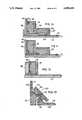
- FIG. 4is a sectional view illustrating an alternative door or panel construction
- FIG. 5is an exploded view of the door or panel of FIG. 4;
- FIG. 6is a sectional view illustrating yet another door or panel using extruded parts and flat sheet material
- FIG. 7is an exploded view of the door or panel of FIG. 6;
- FIG. 8is a sectional view of still another door or panel
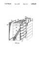
- FIG. 9is an exploded view of an equipment rack comprising an open frame, and a set of closure panels, and a door panel;
- FIGS. 10 to 13, inclusive,are sectional detail views of alternative sealing arrangements.
- an enclosurein the form of a cabinet, has a sidewall 10 with a flange 12 extending perpendicular to the sidewall 10 to serve as the jamb of an opening in the cabinet.
- a closure, door 14extends across the opening with its peripheral region 16 overlying the jamb 12.
- a thin flexible metal lining 18extends across the entire interior surface of the door 14, including the peripheral region 16.
- the metal lining 18is attached to the door 14 by a series of rivets 24, arranged in a row extending parallel to, and spaced inwardly from, the edge of the door 14.
- the strip 19 of lining 18 that is outside the row of rivets i.e. overlying the peripheral region 16,is not attached to the underlying door surface and so may be flexed away from the door 14.
- a channel 20extends along the peripheral region and parallel to the edge of the door 14.
- a strip magnet 22rests loosely in the channel 20 and in alignment with flange 12. The magnet 22 is retained in the channel 20 by the flexible strip 19 that overlies the magnet.
- the flange 12is of magnetic material, for example chromated steel.
- the magnet 22When the door is being closed, the magnet 22 will be attracted to the flange 12, urging the flexible metal strip 19 into contact with the flange 12.
- the magnet 22remains attracted to the flange 12 of the cabinet and so lifts a short distance out of the groove 20.
- the restoring force exerted by flexible strip 19will eventually overcome the magnetic attraction and pull the magnet 22 away from the flange 12.
- the spacing of the rivets 24 laterally of the groove 20provides leverage to assist in pulling the magnet 22 away from the flange 12.
- the flexible metal strip 19at first will flex, then cause the magnet 22 to pivot around its outer edge--the pivot point referenced 26 in FIG. 2. This flexing and pivoting sequence provides a gradual release, an effect that connotes a quality product, rather than an abrupt, jerky release of the magnet 22.
- a sealing arrangement as disclosed hereincan provide a closing force of about 5 ounces per inch or about 3.75 lbs per foot.
- the magnet 22will actually try to close up any mechanical gaps between the door structure and the frame and so will accommodate deviations and inaccuracies, such as panel or door twist or warp.
- the magnet 22 and the flexible strip 19were fastened rigidly to the door, the latter would have to be flexible enough to bend to take up any frame curvature in order to maintain an adequate seal. With embodiments of the present invention the stiffness required need only be sufficient to open the door. If the door structure is rigid, the magnet and flexible metal strip combination will move to take up the tolerances.
- Flexibility of the flexible strip 19may be enhanced by a series of parallel slits, each extending across a major part of the width of the strip.
- movement of the magnetic stripshould be limited so that it will not turn on edge and wedge the metal strip in a permanently outwardly-deflected mode.
- compliance of the sealis a function of magnet movement control and allowable flex in metal strip material.
- both the magnet 22 and channel 20might have lips forming stoops to cooperate and limit travel of the magnet 22 out of the channel 20.
- protuberances 28are provided along the length of the flexible strip 19 where it is to contact the flange 12. Protuberances 28 spaced at approximately four inch intervals have been found to give adequately low resistance and hence adequate low frequency performance.
- the flexible strip 19is very flexible and is held in close proximity to the cabinet by the magnet 22, relatively small spacing is attainable. This ensures a relatively high capacitance between the flexible strip 19 and the cabinet flange 12, which affords improved shielding performance at high frequencies.
- An advantage of embodiments of the inventionis that the seal is maintained without any contribution of force by the door or closure, which simplifies design.
- the relatively large, flat mating surfaceprovides non-critical alignment. Long term reliability is possible because there are no components that take a compression set.
- the arrangementis relatively simple and hence less costly than other approaches.
- FIGS. 4, 5, 6, 7 and 8illustrate alternative constructions for a door. Parts corresponding to those in FIG. 1 have the same reference numerals.
- FIG. 4shows a door 14 formed as an extrusion with grooves 30 in ribs 32.
- the screws or rivets 24are driven into the grooves 30 to secure the flexible lining 18 to the door panel.
- the channel 20 housing the magnet 22is formed between the two endmost ribs.
- An inwardly-projecting lug 34 on one ribserves as a stop to limit movement of the magnet 22 as intimated previously.
- the extruded panelis capped at each end by capping pieces 36 and the lining sheet 18 is then applied to its surface as shown in FIG. 5.
- FIGS. 6 and 7show a door which, in effect, is of so-called panelled-door construction.
- An extruded edge member 40has a recess forming channel 20 housing a magnet 22 and a flange 42 extending towards the middle of the door.
- a panel 44fits into a recess forming flange 42 and carries the flexible lining 18.
- similar edge extrusions 40are provided for the other edges of the panel 44 and corner pieces 46 finish the corners.
- FIG. 8illustrates a door panel formed by a vacuum-formed outer shell 50.
- the flexible lining sheet 18is adhered to the interior surface of the outer shell 50. Instead of a channel for the magnet 22, the lining 18 is stepped to form the flexible strip portion 19 which extends over the magnet 22.
- the adhesivesecures the lining 18 to the medial portion of the door panel, but allows the flexible strip portion 19 to lift away from the outer shell 50.
- an alternative restoring meanscould be provided, perhaps within the channel 20 itself, enabling the flexible strip to be thinner.
- the flange 12itself should be conductive. It has also been found that the protuberances provide a reliable contact over a prolonged time, unlike some finger stock gaskets intended to give resistive/capacitive coupling, but which deteriorate over a period of time due to an accumulation of oxides, necessitating a wiping action to penetrate any oxide build-up.
- Embodiments of the present inventionprovide satisfactory EMI shielding over a relatively large range of frequencies from a few hundred kilohertz to as much as a 1.5 GHz.
- FIG. 9Such an equipment rack is illustrated in FIG. 9 and comprises an open rack or framework 52 of steel box-section material.
- a set of front panels 54are provided at the front of the rack, one for each "drawer”.
- Printed circuit cards 56are mounted between each front panel 54 and a corresponding backplane 58.
- One side of the rack 52is clad with a set of panels 60, one for each opening in the rack 52.
- Each panel 60comprises a slab of lightweight plastics material, for example polystyrene, with a metal lining, a peripheral flexible strip, and a magnet strip (not shown in FIG. 9) as previously described.
- Each panel 60is dimensioned such that its flexible strips will align with the frame members surrounding the opening so that the underlying magnetic strip will adhere thereto. Because the panels 60 are of lightweight material, the magnetic strips will hold each panel 60 securely to the framework 52. No additional fasteners are needed.
- the panelsmay be any suitable size, providing their edges will align with frame members.
- the opposite side of the equipment rack 52is shown clad with a single panel 62, of similar construction to the panels 60, with its magnet strips aligned with the top and bottom rails, respectively, of the rack 52.
- the equipment rack 52is fitted with a door 64, which may be of similar construction to those described hereinbefore.
- the magnet meansmay be provided on the enclosure frame rather than on the closure panel which could further reduce the weight of the closure panel. Such an alternative is illustrated in FIGS. 10, 11, 12 and 13.
- a moulded door panel 70is shown with its interior lined with a metal film 72 which serves as a radiation screen.
- the metal film 72is attached to the door panel 70 by screws or rivets 74 spaced inwardly from the contact region.
- the enclosure frameworkcomprises a frame member 76 which has magnet strips 78 and 80 housed in longitudinal channels 82 and 84, respectively.
- the channels 82 and 84are disposed one on each outwardly facing surface of the frame member 76.
- a contact strip 86 of electrically conductive materialextends between the magnet strips 78 and 80 and around the corner of the frame member 76.
- the door panel 70is attached to the frame member 76 by the magnetic attraction between metal screening film 72 and the magnet strip 80.
- a side panel 88is of similar construction to door panel 70 in that it is formed by a moulding 90 with a metal lining 92 on the inner face.
- the side panel 88is attached to magnet strip 78.
- the surfaces of magnet strips 78 and 80are arranged to lie slightly below the surface of the frame member 76 to ensure that the metal films 72 and 92, respectively, will be pressed onto the contact strip 86 and make good electrical contact.
- FIG. 11which shows a modification of the enclosure of FIG. 10, in which parts corresponding to FIG. 10 have the same reference numeral.
- the modificationcomprises extending metal film 92 around the edge of the side panel 88 as at 94 and extending the metal film 72 on door panel 70 beyond the edge of frame member 76.
- the edge of side panel 88protrudes a little way beyond the frame member 76 so that, when the door panel is pulled into contact with the magnet strip 80 good electrical contact will be made between the metal film 72 and the metal film portion 94.
- the electrical contactis made directly between the door panel 70 and the side panel 88. Consequently, the contact strip 86 of the FIG. 10 embodiment is omitted.
- FIG. 12shows yet another embodiment which has a magnet strip 78 housed in a channel 82 in the frame member 76.
- the door panel 70 and the side panel 88correspond generally with those shown in FIG. 11, but side panel 88 differs in that it has a magnet strip 96 housed in a channel extending along its edge.
- the arrangementis such that the side panel 88 will be attached to the magnet strip 78 in the usual way and the door panel 76 will be attached by means of the metal film 72 adhering to the magnet strip 96.
- the metal film 92 on the side panel 88wraps around the edge of the side panel 88 and is abutted by the metal film 72 on the door panel 70. Good electrical contact is assured by arranging for the edge portion of metal film 92 to protrude beyond the magnet strip 96 and the frame member 76 when the side panel 88 is attached.
- FIG. 13uses a single magnet strip 100 housed in a channel 102 in a frame member 104.
- the magnet strip 100is positioned with its face at an oblique angle to the front and side surfaces of the enclosure.
- a door panel 106 and a side panel 108are similar to each other and comprises moulded panels having flanges 110 and 112 along their respective edges and metal linings 114 and 116, respectively.
- Each of the flanges 110 and 112extends obliquely relative to the associated panel at an angle corresponding to that of the magnet strip 100, vis. 45 degrees.
- the door panel 106 and side panel 108are attached to the frame member 104 by attaching the portions of the metal films 114 and 116 to the single magnet strip 100.
- a contact strip 118of copper, phosphor bronze or other suitable conductive material, is located in a longitudinal channel 120 in the outer face of magnet strip 100.
- the contact strip 118bridges between the metal film 114 and 116 to connect the door panel 106 and side panel 108 together electrically.
- the contact strip 18may project beyond the surface of the magnet strip 100 to ensure good electrical contact.
- an advantage of embodiments of the inventionis that the flexible strip need not be particularly resilient and so may be made from cheaper material than, say, beryllium copper.
- magnetically-attached cladding panelsare quick and easy to retrofit to existing equipment racks. Moreover, they are quick and easy to remove for access to the equipment within since a limited number of permanent fasteners, (if any), are required.
Landscapes
- Engineering & Computer Science (AREA)
- Microelectronics & Electronic Packaging (AREA)
- Shielding Devices Or Components To Electric Or Magnetic Fields (AREA)
- External Artificial Organs (AREA)
- Specific Sealing Or Ventilating Devices For Doors And Windows (AREA)
- Special Wing (AREA)
Abstract
Description
Claims (34)
Applications Claiming Priority (1)
| Application Number | Priority Date | Filing Date | Title |
|---|---|---|---|
| CA000604899ACA1318014C (en) | 1989-07-06 | 1989-07-06 | Sealing enclosures against electromagnetic interference |
Publications (1)
| Publication Number | Publication Date |
|---|---|
| US4999459Atrue US4999459A (en) | 1991-03-12 |
Family
ID=4140305
Family Applications (1)
| Application Number | Title | Priority Date | Filing Date |
|---|---|---|---|
| US07/378,804Expired - LifetimeUS4999459A (en) | 1989-07-06 | 1989-07-12 | Sealing enclosures against electromagnetic interference |
Country Status (7)
| Country | Link |
|---|---|
| US (1) | US4999459A (en) |
| EP (1) | EP0485385B1 (en) |
| JP (2) | JPH0364099A (en) |
| AT (1) | ATE111678T1 (en) |
| CA (1) | CA1318014C (en) |
| DE (1) | DE69012571T2 (en) |
| WO (1) | WO1991001079A1 (en) |
Cited By (24)
| Publication number | Priority date | Publication date | Assignee | Title |
|---|---|---|---|---|
| US5160806A (en)* | 1989-11-29 | 1992-11-03 | Nec Corporation | Electromagnetic shielding member and electromagnetic shielding case |
| US6193892B1 (en) | 1999-03-03 | 2001-02-27 | Promega Corporation | Magnetic separation assembly and method |
| US6483024B1 (en) | 2000-06-30 | 2002-11-19 | Silicon Graphics, Inc. | Panel gasket |
| US20050006118A1 (en)* | 2003-06-26 | 2005-01-13 | Emc Corporation | Adaptable emi/rfi shielding for a front-panel attachment to an enclosure |
| US20050264142A1 (en)* | 2004-05-25 | 2005-12-01 | Emc Corporation | Locking mechanism for securing the bezel of an electronics enclosure to a rack structure |
| US20090008146A1 (en)* | 2007-03-16 | 2009-01-08 | Michael William Oleske | Optimizing in-building wireless signal propagation while ensuring data network security |
| US7585005B1 (en) | 2006-03-23 | 2009-09-08 | Emc Corporation | Locking mechanism for securing bezels |
| US20100201461A1 (en)* | 2009-02-09 | 2010-08-12 | Marc Cordes | Methods And Devices For Reducing Communication And Power Signal Leakages From Filter Assemblies |
| US20190124800A1 (en)* | 2017-10-19 | 2019-04-25 | Robert Francis Bodi | Conductive Construction Panel and Method of Use |
| US10638634B1 (en) | 2019-06-21 | 2020-04-28 | International Business Machines Corporation | Rack-mountable assembly with electromagnetic shielding structure(s) |
| US10764970B2 (en) | 2016-01-08 | 2020-09-01 | Whirlpool Corporation | Multiple cavity microwave oven insulated divider |
| US10772165B2 (en) | 2018-03-02 | 2020-09-08 | Whirlpool Corporation | System and method for zone cooking according to spectromodal theory in an electromagnetic cooking device |
| US10820382B2 (en) | 2016-01-28 | 2020-10-27 | Whirlpool Corporation | Method and apparatus for delivering radio frequency electromagnetic energy to cook foodstuff |
| US10827570B2 (en) | 2016-02-15 | 2020-11-03 | Whirlpool Corporation | Method and apparatus for delivering radio frequency electromagnetic energy to cook foodstuff |
| US10827569B2 (en) | 2017-09-01 | 2020-11-03 | Whirlpool Corporation | Crispness and browning in full flat microwave oven |
| US10834842B1 (en) | 2019-06-21 | 2020-11-10 | International Business Machines Corporation | Rack-mountable assembly with spring-hinged mounting bracket(s) |
| US10904961B2 (en) | 2015-03-06 | 2021-01-26 | Whirlpool Corporation | Method of calibrating a high power amplifier for a radio frequency power measurement system |
| US10904962B2 (en) | 2015-06-03 | 2021-01-26 | Whirlpool Corporation | Method and device for electromagnetic cooking |
| US10912160B2 (en) | 2018-07-19 | 2021-02-02 | Whirlpool Corporation | Cooking appliance |
| US11039510B2 (en) | 2017-09-27 | 2021-06-15 | Whirlpool Corporation | Method and device for electromagnetic cooking using asynchronous sensing strategy for resonant modes real-time tracking |
| US11191133B2 (en) | 2014-09-17 | 2021-11-30 | Whirlpool Corporation | Direct heating through patch antennas |
| US11357141B2 (en)* | 2019-06-19 | 2022-06-07 | Go Team Ccr, Llc | EMP protection for structures having coal combustion residual components |
| US11404758B2 (en) | 2018-05-04 | 2022-08-02 | Whirlpool Corporation | In line e-probe waveguide transition |
| US11483905B2 (en) | 2016-01-08 | 2022-10-25 | Whirlpool Corporation | Method and apparatus for determining heating strategies |
Families Citing this family (2)
| Publication number | Priority date | Publication date | Assignee | Title |
|---|---|---|---|---|
| DE59712672D1 (en)* | 1996-01-19 | 2006-07-20 | Helmut Kahl | ELECTRICALLY SHIELDING HOUSING |
| JP7088535B2 (en)* | 2018-03-29 | 2022-06-21 | メディカル・エイド株式会社 | Vehicle with electromagnetic wave shield room and electromagnetic wave shield room |
Citations (6)
| Publication number | Priority date | Publication date | Assignee | Title |
|---|---|---|---|---|
| US3240862A (en)* | 1964-07-06 | 1966-03-15 | Mayville Metal Products Co | Adjustable gasket support for rfi shielded cabinets |
| GB1072751A (en)* | 1964-02-21 | 1967-06-21 | Marconi Co Ltd | Improvements in or relating to housings for radio and like high frequency apparatus |
| US3889043A (en)* | 1972-06-09 | 1975-06-10 | Ducros Emile Paul J J | Earthing joint for shielding chambers electrically and electromagnetically |
| US3969572A (en)* | 1975-03-05 | 1976-07-13 | Ncr Corporation | Electromagnetic interference shielding gasket for light-weight equipment enclosures |
| CA1164533A (en)* | 1980-06-25 | 1984-03-27 | Earl Birk | Microwave oven door having a conformable screen |
| US4652695A (en)* | 1983-06-20 | 1987-03-24 | Pawling Corporation | Mesh-covered core strip for high frequency RFI/EMI radiation shielding |
- 1989
- 1989-07-06CACA000604899Apatent/CA1318014C/ennot_activeExpired - Fee Related
- 1989-07-12USUS07/378,804patent/US4999459A/ennot_activeExpired - Lifetime
- 1990
- 1990-03-21WOPCT/CA1990/000100patent/WO1991001079A1/enactiveIP Right Grant
- 1990-03-27EPEP90905402Apatent/EP0485385B1/ennot_activeExpired - Lifetime
- 1990-03-27ATAT90905402Tpatent/ATE111678T1/ennot_activeIP Right Cessation
- 1990-03-27DEDE69012571Tpatent/DE69012571T2/ennot_activeExpired - Fee Related
- 1990-07-06JPJP2179425Apatent/JPH0364099A/enactivePending
- 2000
- 2000-06-05JPJP2000167140Apatent/JP2001024376A/enactivePending
Patent Citations (6)
| Publication number | Priority date | Publication date | Assignee | Title |
|---|---|---|---|---|
| GB1072751A (en)* | 1964-02-21 | 1967-06-21 | Marconi Co Ltd | Improvements in or relating to housings for radio and like high frequency apparatus |
| US3240862A (en)* | 1964-07-06 | 1966-03-15 | Mayville Metal Products Co | Adjustable gasket support for rfi shielded cabinets |
| US3889043A (en)* | 1972-06-09 | 1975-06-10 | Ducros Emile Paul J J | Earthing joint for shielding chambers electrically and electromagnetically |
| US3969572A (en)* | 1975-03-05 | 1976-07-13 | Ncr Corporation | Electromagnetic interference shielding gasket for light-weight equipment enclosures |
| CA1164533A (en)* | 1980-06-25 | 1984-03-27 | Earl Birk | Microwave oven door having a conformable screen |
| US4652695A (en)* | 1983-06-20 | 1987-03-24 | Pawling Corporation | Mesh-covered core strip for high frequency RFI/EMI radiation shielding |
Non-Patent Citations (1)
| Title |
|---|
| Bunk, Electromagnetic Shielding, Machine Design, Jul. 6, 1967.* |
Cited By (27)
| Publication number | Priority date | Publication date | Assignee | Title |
|---|---|---|---|---|
| US5160806A (en)* | 1989-11-29 | 1992-11-03 | Nec Corporation | Electromagnetic shielding member and electromagnetic shielding case |
| US6193892B1 (en) | 1999-03-03 | 2001-02-27 | Promega Corporation | Magnetic separation assembly and method |
| US6483024B1 (en) | 2000-06-30 | 2002-11-19 | Silicon Graphics, Inc. | Panel gasket |
| US20050006118A1 (en)* | 2003-06-26 | 2005-01-13 | Emc Corporation | Adaptable emi/rfi shielding for a front-panel attachment to an enclosure |
| US6870093B2 (en) | 2003-06-26 | 2005-03-22 | Emc Corporation | Adaptable EMI/RFI shielding for a front-panel attachment to an enclosure |
| US7232193B2 (en) | 2004-05-25 | 2007-06-19 | Emc Corporation | Locking mechanism for securing the bezel of an electronics enclosure to a rack structure |
| US20050264142A1 (en)* | 2004-05-25 | 2005-12-01 | Emc Corporation | Locking mechanism for securing the bezel of an electronics enclosure to a rack structure |
| US7585005B1 (en) | 2006-03-23 | 2009-09-08 | Emc Corporation | Locking mechanism for securing bezels |
| US20090008146A1 (en)* | 2007-03-16 | 2009-01-08 | Michael William Oleske | Optimizing in-building wireless signal propagation while ensuring data network security |
| US20100201461A1 (en)* | 2009-02-09 | 2010-08-12 | Marc Cordes | Methods And Devices For Reducing Communication And Power Signal Leakages From Filter Assemblies |
| US8830698B2 (en)* | 2009-02-09 | 2014-09-09 | InTech Defense, LLC. | Methods and devices for reducing communication and power signal leakages from filter assemblies |
| US11191133B2 (en) | 2014-09-17 | 2021-11-30 | Whirlpool Corporation | Direct heating through patch antennas |
| US10904961B2 (en) | 2015-03-06 | 2021-01-26 | Whirlpool Corporation | Method of calibrating a high power amplifier for a radio frequency power measurement system |
| US10904962B2 (en) | 2015-06-03 | 2021-01-26 | Whirlpool Corporation | Method and device for electromagnetic cooking |
| US11483905B2 (en) | 2016-01-08 | 2022-10-25 | Whirlpool Corporation | Method and apparatus for determining heating strategies |
| US10764970B2 (en) | 2016-01-08 | 2020-09-01 | Whirlpool Corporation | Multiple cavity microwave oven insulated divider |
| US10820382B2 (en) | 2016-01-28 | 2020-10-27 | Whirlpool Corporation | Method and apparatus for delivering radio frequency electromagnetic energy to cook foodstuff |
| US10827570B2 (en) | 2016-02-15 | 2020-11-03 | Whirlpool Corporation | Method and apparatus for delivering radio frequency electromagnetic energy to cook foodstuff |
| US10827569B2 (en) | 2017-09-01 | 2020-11-03 | Whirlpool Corporation | Crispness and browning in full flat microwave oven |
| US11039510B2 (en) | 2017-09-27 | 2021-06-15 | Whirlpool Corporation | Method and device for electromagnetic cooking using asynchronous sensing strategy for resonant modes real-time tracking |
| US20190124800A1 (en)* | 2017-10-19 | 2019-04-25 | Robert Francis Bodi | Conductive Construction Panel and Method of Use |
| US10772165B2 (en) | 2018-03-02 | 2020-09-08 | Whirlpool Corporation | System and method for zone cooking according to spectromodal theory in an electromagnetic cooking device |
| US11404758B2 (en) | 2018-05-04 | 2022-08-02 | Whirlpool Corporation | In line e-probe waveguide transition |
| US10912160B2 (en) | 2018-07-19 | 2021-02-02 | Whirlpool Corporation | Cooking appliance |
| US11357141B2 (en)* | 2019-06-19 | 2022-06-07 | Go Team Ccr, Llc | EMP protection for structures having coal combustion residual components |
| US10638634B1 (en) | 2019-06-21 | 2020-04-28 | International Business Machines Corporation | Rack-mountable assembly with electromagnetic shielding structure(s) |
| US10834842B1 (en) | 2019-06-21 | 2020-11-10 | International Business Machines Corporation | Rack-mountable assembly with spring-hinged mounting bracket(s) |
Also Published As
| Publication number | Publication date |
|---|---|
| DE69012571D1 (en) | 1994-10-20 |
| JPH0364099A (en) | 1991-03-19 |
| DE69012571T2 (en) | 1995-01-26 |
| EP0485385B1 (en) | 1994-09-14 |
| WO1991001079A1 (en) | 1991-01-24 |
| JP2001024376A (en) | 2001-01-26 |
| CA1318014C (en) | 1993-05-18 |
| ATE111678T1 (en) | 1994-09-15 |
| EP0485385A1 (en) | 1992-05-20 |
Similar Documents
| Publication | Publication Date | Title |
|---|---|---|
| US4999459A (en) | Sealing enclosures against electromagnetic interference | |
| US6140577A (en) | Electronic chassis electro-magnetic interference seal and sealing device | |
| US5015802A (en) | Computer casing connector | |
| US4820885A (en) | Magnetic gasket for shielding against electromagnetic radiation | |
| EP0366363A1 (en) | Electromagnetic shielding and environmental sealing device | |
| US20030081399A1 (en) | Tool-less access cover and EMI tight access door | |
| US4761516A (en) | Electromagnetic interference shielding device | |
| US4705916A (en) | EMI gasket retaining mechanism for electronic equipment | |
| US4786758A (en) | Door shield for shielded enclosure | |
| US6865805B2 (en) | Device and method of forming a unitary electrically shielded panel | |
| EP0169598B1 (en) | Ventilation panel for electromagnetic shielding | |
| CA1171465A (en) | Oven door construction in a microwave oven | |
| JPH0691333B2 (en) | Sealing device of metal cabinet for shielding electromagnetic field | |
| US6870093B2 (en) | Adaptable EMI/RFI shielding for a front-panel attachment to an enclosure | |
| GB1588037A (en) | Door formicrowave oven | |
| US5691503A (en) | Electro-magnetically shielded door hinge | |
| KR19980033115A (en) | Sealed Module Support Structure | |
| JP2001057495A (en) | Surrounding body | |
| US6291765B1 (en) | Electromagnetically shielded housing having metal parts snap-connected via a spring contact strip | |
| EP0668714B1 (en) | Rack apparatus, for containing electric components therein, having improved shielding function | |
| JP3810325B2 (en) | Electromagnetic shielding door lower shield structure | |
| KR880000226B1 (en) | Electronic range | |
| JPH05218674A (en) | Electromagnetic shielding device | |
| US6937119B1 (en) | High frequency apparatus | |
| JPH07231188A (en) | Shielding case |
Legal Events
| Date | Code | Title | Description |
|---|---|---|---|
| AS | Assignment | Owner name:NORTHERN TELECOM LIMITED, P.O. BOX 6123, STATION A Free format text:ASSIGNMENT OF ASSIGNORS INTEREST.;ASSIGNOR:BELL-NORTHERN RESEARCH LTD.;REEL/FRAME:005258/0906 Effective date:19900111 Owner name:BELL-NORTHERN RESEARCH LTD., P.O. BOX 3511, STATIO Free format text:ASSIGNMENT OF ASSIGNORS INTEREST.;ASSIGNORS:SMITH, KEVIN;ZIMMERMANN, DETLEF;REEL/FRAME:005258/0905;SIGNING DATES FROM 19891215 TO 19900111 | |
| STCF | Information on status: patent grant | Free format text:PATENTED CASE | |
| FEPP | Fee payment procedure | Free format text:PAYOR NUMBER ASSIGNED (ORIGINAL EVENT CODE: ASPN); ENTITY STATUS OF PATENT OWNER: LARGE ENTITY | |
| FPAY | Fee payment | Year of fee payment:4 | |
| FPAY | Fee payment | Year of fee payment:8 | |
| AS | Assignment | Owner name:NORTEL NETWORKS CORPORATION, CANADA Free format text:CHANGE OF NAME;ASSIGNOR:NORTHERN TELECOM LIMITED;REEL/FRAME:010567/0001 Effective date:19990429 | |
| AS | Assignment | Owner name:NORTEL NETWORKS LIMITED, CANADA Free format text:CHANGE OF NAME;ASSIGNOR:NORTEL NETWORKS CORPORATION;REEL/FRAME:011195/0706 Effective date:20000830 Owner name:NORTEL NETWORKS LIMITED,CANADA Free format text:CHANGE OF NAME;ASSIGNOR:NORTEL NETWORKS CORPORATION;REEL/FRAME:011195/0706 Effective date:20000830 | |
| REMI | Maintenance fee reminder mailed | ||
| FPAY | Fee payment | Year of fee payment:12 | |
| SULP | Surcharge for late payment | Year of fee payment:11 |