US4998713A - Needle connector - Google Patents
Needle connectorDownload PDFInfo
- Publication number
- US4998713A US4998713AUS07/463,243US46324390AUS4998713AUS 4998713 AUS4998713 AUS 4998713AUS 46324390 AUS46324390 AUS 46324390AUS 4998713 AUS4998713 AUS 4998713A
- Authority
- US
- United States
- Prior art keywords
- needle
- connector
- set forth
- seal
- site
- Prior art date
- Legal status (The legal status is an assumption and is not a legal conclusion. Google has not performed a legal analysis and makes no representation as to the accuracy of the status listed.)
- Expired - Lifetime
Links
Images


Classifications
- A—HUMAN NECESSITIES
- A61—MEDICAL OR VETERINARY SCIENCE; HYGIENE
- A61M—DEVICES FOR INTRODUCING MEDIA INTO, OR ONTO, THE BODY; DEVICES FOR TRANSDUCING BODY MEDIA OR FOR TAKING MEDIA FROM THE BODY; DEVICES FOR PRODUCING OR ENDING SLEEP OR STUPOR
- A61M39/00—Tubes, tube connectors, tube couplings, valves, access sites or the like, specially adapted for medical use
- A61M39/02—Access sites
- A61M39/04—Access sites having pierceable self-sealing members
- Y—GENERAL TAGGING OF NEW TECHNOLOGICAL DEVELOPMENTS; GENERAL TAGGING OF CROSS-SECTIONAL TECHNOLOGIES SPANNING OVER SEVERAL SECTIONS OF THE IPC; TECHNICAL SUBJECTS COVERED BY FORMER USPC CROSS-REFERENCE ART COLLECTIONS [XRACs] AND DIGESTS
- Y10—TECHNICAL SUBJECTS COVERED BY FORMER USPC
- Y10S—TECHNICAL SUBJECTS COVERED BY FORMER USPC CROSS-REFERENCE ART COLLECTIONS [XRACs] AND DIGESTS
- Y10S604/00—Surgery
- Y10S604/905—Aseptic connectors or couplings, e.g. frangible, piercable
Definitions
- This inventionrelates to a needle connector. More particularly this invention relates to a needle connector for a Y-site connector.
- U.S. Pat. No. 4,752,292describes a medical connector wherein a needle is contained in a recessed manner within a narrow cap member.
- the cap memberis designed to fit snugly over an entry port structure with the needle positioned to pierce a seal on the entry port structure when the cap member is seated in place.
- a needle connector assemblyis composed of one connector half which receives a needle in recessed manner and a second connector half which contains a seal which can be pierced by the needle when the two halves are brought together
- Y-site connectorsare generally made with a straight tubular portion and a hollow arm which extends laterally from the hollow portion. Where the Y-site connector is provided with a seal at the end of the tubular portion adjacent the lateral arm, difficulties may arise in securing a needle connector in place over the seal, should the lateral arm interfere with the needle connector. Accordingly, efforts have been made to provide a needle connector which can envelope the entire Y-site connector.
- one known connectorhas been provided with a tubular part in which a needle is recessed as well as a coaxially extending tubular part having a slot at one end for fitting over the arm of a Y-site neck.
- the connectoris mounted over the end of a Y-site connector with the needle piercing through a seal in the end of a tubular tubular portion of the Y-site connector.
- the arm of the Y-site connectormoves into the slot provided by the extending tubular part of the needle connector.
- the needle connectorcan be turned on the Y-site connector to secure a lug on the tubular portion against the arm of the Y-site connector.
- the interior of the needle connectoris spaced from the exterior of the Y-site connector, the interior volume of the needle connector may become contaminated in time, particularly in the area surrounding the needle.
- the inventionprovides a needle connector constructed to provide a seal-tight fit with a Y-site connector.
- the needle connectoris composed of three components, i.e. a pair of tubular parts and a hollow needle.
- the needle connectoris composed of two components and cooperates with a removable needle assembly.
- one tubular partforms a shielded connector which has a chamber at one end for receiving a Y-site connector, a slot for passage over an arm of the Y-site connector and a second chamber at an opposite end coaxial of the first chamber.
- the shielded connectorhas a conical portion sized to sealingingly engage with a seal at the end of a Y-site connector.
- the needleis fixedly mounted in the shielded connector in axial alignment with the chambers in order to communicate these chambers with each other.
- the needleprojects into the first chamber in order to pass through a seal at one end of a Y-site connector.
- the second tubular partis in the form of a ring which is movably mounted on the first tubular part for example, being rotatably secured to the first tubular part in coaxial relation.
- This ringalso has a slot for passage over the arm of the Y-site connector as well as a cam surface at an end edge for engaging the arm of the Y-site connector.
- the needle connectoris slid over a Y-site connector with the slot of the shielded connector receiving the lateral arm of the Y-site connector.
- the needlepierces through the seal on the Y-site connector while the seal engages with the internal conical portion of the shielded connector.
- the ringis rotated on the shielded connector so as to bring the cam surface of the ring against the lateral arm of the Y-site connector.
- Continued rotationforces the arm, and thus the Y-site connector, further into the needle connector. This, in turn, causes the seal to further engage with the shielded connector about the environment of the needle.
- the construction of the needle connectoris such as to be mounted over differently sized Y-site connectors.
- the shielded connector containing the recessed needlecan be sized to sealingly engage with different diameters of seals located on the ends of a Y-site connector.
- the needleis removeably mounted in the part which forms the shielded connector of the needle connector. This permits the needle to be changed from time to time, for example, each time a dose of medication is to be given to a patient.
- the needleis mounted in a needle hub which, in turn, is removeably mounted within the shielded connector part of the needle connector, for example in a threaded relation.
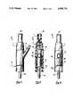
- FIG. 1illustrates a cross sectional view of the needle connector mounted in place on a Y-site connector in accordance with the invention
- FIG. 2illustrates a front view of a needle connector mounted on a Y-site connector in accordance with the invention
- FIG. 3illustrates an exploded view of the needle connector of FIG. 1;
- FIG. 4illustrates a perspective view of a modified needle connector mounted on a Y-site connector in accordance with the invention
- FIG. 5illustrates a cross sectional view of the needle connector of FIG. 4
- FIG. 6illustrates a front view of the needle connector of FIG. 4
- FIG. 7illustrates a cross-sectional view of a further modified needle connector constructed in accordance with the invention:
- FIG. 8illustrates a front View of the needle connector of FIG. 7 in place
- FIG. 9illustrates a view of a ring of the needle connector of FIG. 8
- FIG. 10illustrates a view of the ring of FIG. 9 rotated 90°.
- FIG. 11illustrates a cross-sectional view of a o modified needle connector constructed in accordance with the invention:
- FIG. 12illustrates a view of the needle connector of FIG. 11 during removal of a needle hub and needle assembly
- FIG. 13illustrates a further modified needle connector constructed in accordance with the invention.
- the needle connector 10is composed of three parts, i.e. a pair of telescoping tubular parts 11, 12 and a needle 13. As indicated, the needle connector 10 is sized for mounting a Y-site connector 14 which includes a straight tubular portion 15 and an arm 16 which extends laterally from the tubular portion 15. As indicated, the tubular portion 15 also carries a seal 17 at one end for closing off the tubular portion 15. The opposite end receives a tubing 18 which extends, for example to an intravenous line (not shown)
- the Y-site connector 14is of conventional construction and need not be further described.
- the upper tubular part 11 of the needle connector 10forms a shielded connector of tubular shape and has a chamber 19 for receiving the tubular portion 15 of the Y-site connector 14 as well as a second chamber 20 at the upper end, as viewed, for receiving, for example, a syringe or other means for supplying a fluid.
- the needle 13is hollow so as to communicate the chambers 20, 19 with each other for the passage of a fluid therebetween.
- the shielded connector 11also has an axial slot 21 which is sized for passage over the arm 16 of the Y-site connector 14.
- a peripheral bead or rim 22is provided on the end of the shielded connector 11 while the Other tubular part 12 which is in the form of a ring has an annular groove 23 for receiving the rim 22 in snap-fit relation
- the bead 22 and groove 23serve to form a snap-fit arrangement for locking the tubular parts 11, 12 together in freely rotatable relation to each other about a common axis.
- the shielded connector 11also has a conical portion 24 which provides an internal conical surface 25 for sealing engagement with the seal 17.
- the ring 12functions as a locking ring and has a cam surface 26 at an end edge as well as an axial slot 27 which extends over the entire length of the ring 12.
- a plurality of depressions 28are provided along the cam surface 26.
- the slots 21, 27 of the tubular parts 11, 12 of the needle connector 10are aligned. Thereafter, the needle connector 10 is slid over the end of the Y-site connector 14 with the arm 16 passing first through the slot 27 of the ring 12 and then into the slot 21 of the shielded connector 11. During this time, the needle 13 pierces through the seal 17 into communication with the interior of the Y-site connector tubular portion 15 as indicated in FIG. 1.
- the ring 12is rotated so as to bring a depression 28 into alignment with the arm 16 so as to lock the needle connector 10 to the Y-site connector 14.
- the ring 12can be rotated more or less so as to force the arm 16 of the Y-site connector in a direction towards the needle 13 so as to increase the force sealing the seal 17 against the conical surface 25 within the shielded connector 11.
- the cam surface 26may be provided with a multiplicity of depressions or detents 28 in Which the arm 16 can be seated in order to lock the needle connector 10 to the Y-site connector 14.
- the seal-tight fit of the seal 17 of the Y-site connector 14 in the shielded connector 11prevents contamination of the space surrounding the needle 13 during use.
- a suitable supply meansmay be connected to the remaining chamber 20 of the needle connector 10 so as to infuse fluid into the Y-site connector 14, for example, a syringe may be releaseably secured to the end of the needle connector 10 via ears 28' on the outer surface of the shielded connector.
- the needle connector 10'may be constructed with the telescoping parts 11, 12 in reverse order. That is, the ring 12 may be disposed to rotate within the shielded connector 11.
- the ring 12may be provided with an enlarged shoulder portion 29 having an outer diameter equal to or substantially equal to the outer diameter of the shielded connector 11.
- this enlarged part 29may be provided with a knurled surface 30 (see FIG. 6).
- the needle connector 10may alternatively be made such that the shielded connector 11 has a tubular skirt 31 and a tubular wall 32 disposed in concentric relation to each other and in spaced apart relation so as to receiVe a sleeve-like portion 33 of the ring 12".
- the skirt 31is provided with a peripheral bead 34 while the ring 12 is provided with an internal groove 35 to receive the bead 34 in locking relation to prevent axial displacement between the components while permitting rotation of the components 11, 12 relative to each other.
- the needle connector 36may be constructed of two parts, i.e. a tubular part (shielded connector) 37 and a ring (not shown) similar to that described above while the needle 13 is removeably mounted within the connector 36.
- the needle 13is mounted in a needle hub 38 to form an assembly which is removeably mounted within the shielded connector 37.
- the needle hub 38is of generally conventional structure and is sized so as to be fitted within the shielded connector 37.
- the needle hub 38carries a collar 39 at one end from which a pair of ears 40 project so as to threadably engage with an internal thread 41 on the anterior wall of the shielded connector 37.
- a male luer type connection 42is provided within the shielded connector 37 to provide a passage 43 communicating the chamber 20 with the hollow needle 13.
- a dose of medication or other fluidmay then be dispensed through the male luer type connection 42 into and through the hollow needle 13 into a Y-site connector 14 inserted within the needle connector 36.
- a transparent tube 44 or the likeis inserted into the needle connector 37 to engage over the outer circumference of the needle hub 38.
- the tube 44carries a flange 45 at the end which may be provided with internal notches (not shown) to engage with ribs 46 extending longitudinally along the needle hub 38.
- the tube 44can be turned so the needle hub 38 is unthreaded from the thread 41 of the shielded connector 37 and then removed. Insertion of a fresh needle hub 38 with a needle 37 is effected in a reverse manner.
- the seal 17 at the end of the Y-site connector 14is brought into abutment with the distal end of the needle hub 38.
- the needle hub 38is provided with a depending annular skirt 47 about the needle 13 which penetrates slightly into the seal 17 to maintain an effective seal about the needle 13.
- a sealmay not be effected when the needle 13 penetrates the rubber seal 17.
- the needle 13When a removable needle is used, the needle 13 may be changed prior to each medication at the discretion of the hospital or the entity administrating the medication. In this way, the potential effect of having a contaminated area immediately adjacent to the penetrating needle 13 is eliminated and there is no need for a non-contaminated zone. In this case, the needle is removed and exchanged for a fresh sterile one. In addition, the rubber surface of the seal 17 is cleaned with an antiseptic, such as povidone iodine, prior to reinsertion of a sterile needle.
- an antisepticsuch as povidone iodine
- the ring (not shown) of the needle connector 36is rotated more or less so as to cause engagement of the seal 17 of the Y-site connector 14 against the needle hub 38.
- the cam surface of the ringmay be suitably shaped to effect a different amount of movement of the needle connector 36 over the Y-site connector 14 from one recess of the cam surface to the next recess.
- a needle hub 38may be provided with a resiliently collapsible ring or sleeve 48, for example of rubber in order to effect a seal about the needle 13 when the needle connector 36 is fitted over a Y-site connector 14.
- a sleeve 48would be able to collapse to different degrees between the needle hub 38 and the seal 17 depending upon the amount of penetration of the Y-site connector 14 into the needle connector 10.
- the ringis attached to the shielded connector in such a fashion as to be free to rotate around the axis of the connector.
- the ring 12can be rotated to progressively close the slot 21 and engage the arm 16.
- the action of the ring 12is positive and can readily achieve a good tight fit.
- the inventionthus provides a needle connector which can be readily mounted on all types of extending Y-site connectors while achieving a secure seal about the needle of the needle connector to prevent contamination.
- the inventionprovides a needle connector of relatively simple construction which can be readily manipulated and locked in place on a Y-site connector.
Landscapes
- Health & Medical Sciences (AREA)
- Heart & Thoracic Surgery (AREA)
- Animal Behavior & Ethology (AREA)
- General Health & Medical Sciences (AREA)
- Anesthesiology (AREA)
- Biomedical Technology (AREA)
- Hematology (AREA)
- Life Sciences & Earth Sciences (AREA)
- Pulmonology (AREA)
- Engineering & Computer Science (AREA)
- Public Health (AREA)
- Veterinary Medicine (AREA)
- Infusion, Injection, And Reservoir Apparatuses (AREA)
- Connections By Means Of Piercing Elements, Nuts, Or Screws (AREA)
- Multi-Conductor Connections (AREA)
- Printers Or Recording Devices Using Electromagnetic And Radiation Means (AREA)
Abstract
Description
Claims (31)
Priority Applications (7)
| Application Number | Priority Date | Filing Date | Title |
|---|---|---|---|
| US07/463,243US4998713A (en) | 1990-01-10 | 1990-01-10 | Needle connector |
| CA002032769ACA2032769C (en) | 1990-01-10 | 1990-12-20 | Needle connector |
| DE69013487TDE69013487D1 (en) | 1990-01-10 | 1990-12-21 | Needle clutch. |
| EP90314183AEP0438909B1 (en) | 1990-01-10 | 1990-12-21 | A needle connector |
| AT90314183TATE112972T1 (en) | 1990-01-10 | 1990-12-21 | NEEDLE CLUTCH. |
| AU68547/90AAU637442B2 (en) | 1990-01-10 | 1990-12-28 | Needle connector |
| JP3001606AJPH069613B2 (en) | 1990-01-10 | 1991-01-10 | Needle connector |
Applications Claiming Priority (1)
| Application Number | Priority Date | Filing Date | Title |
|---|---|---|---|
| US07/463,243US4998713A (en) | 1990-01-10 | 1990-01-10 | Needle connector |
Publications (1)
| Publication Number | Publication Date |
|---|---|
| US4998713Atrue US4998713A (en) | 1991-03-12 |
Family
ID=23839424
Family Applications (1)
| Application Number | Title | Priority Date | Filing Date |
|---|---|---|---|
| US07/463,243Expired - LifetimeUS4998713A (en) | 1990-01-10 | 1990-01-10 | Needle connector |
Country Status (7)
| Country | Link |
|---|---|
| US (1) | US4998713A (en) |
| EP (1) | EP0438909B1 (en) |
| JP (1) | JPH069613B2 (en) |
| AT (1) | ATE112972T1 (en) |
| AU (1) | AU637442B2 (en) |
| CA (1) | CA2032769C (en) |
| DE (1) | DE69013487D1 (en) |
Cited By (52)
| Publication number | Priority date | Publication date | Assignee | Title |
|---|---|---|---|---|
| US5071413A (en)* | 1990-06-13 | 1991-12-10 | Utterberg David S | Universal connector |
| EP0497229A1 (en) | 1991-01-30 | 1992-08-05 | Vincent L. Vaillancourt | Closed system fluid connector assembly |
| US5151090A (en)* | 1990-10-19 | 1992-09-29 | Abbott Laboratories | Syringe and needle guard assembly |
| WO1993010846A1 (en)* | 1991-12-03 | 1993-06-10 | Safegrip, Inc. | A unified medical fluid system |
| US5281206A (en)* | 1983-01-24 | 1994-01-25 | Icu Medical, Inc. | Needle connector with rotatable collar |
| US5282794A (en)* | 1992-08-24 | 1994-02-01 | Tri-State Hospital Supply Corporation | Guarded needle and retaining means |
| US5330450A (en)* | 1983-01-24 | 1994-07-19 | Icu Medical, Inc. | Medical connector |
| US5356396A (en)* | 1992-09-29 | 1994-10-18 | Medical Associates Network Inc. | Infusion apparatus |
| US5545152A (en)* | 1994-10-28 | 1996-08-13 | Minimed Inc. | Quick-connect coupling for a medication infusion system |
| USD380262S (en)* | 1995-06-26 | 1997-06-24 | Minimed Inc. | Quick disconnect coupling |
| US5658260A (en) | 1988-01-25 | 1997-08-19 | Baxter International Inc. | Bayonet lock cannula for pre-slit y-site |
| US5685866A (en)* | 1991-12-18 | 1997-11-11 | Icu Medical, Inc. | Medical valve and method of use |
| US5688254A (en)* | 1983-01-24 | 1997-11-18 | Icu Medical, Inc. | Medical connector |
| US5776125A (en) | 1991-07-30 | 1998-07-07 | Baxter International Inc. | Needleless vial access device |
| US5797897A (en) | 1988-01-25 | 1998-08-25 | Baxter International Inc. | Pre-slit injection site and tapered cannula |
| US5810398A (en)* | 1992-10-02 | 1998-09-22 | Pall Corporation | Fluid delivery systems and methods and assemblies for making connections |
| US5868433A (en)* | 1992-10-02 | 1999-02-09 | Pall Corporation | Connector assembly |
| US5957898A (en) | 1997-05-20 | 1999-09-28 | Baxter International Inc. | Needleless connector |
| US6193697B1 (en)* | 1987-03-17 | 2001-02-27 | Baxter International Inc. | Pre-slit injection site and tapered cannula |
| US6213996B1 (en) | 1988-01-25 | 2001-04-10 | Baxter International Inc. | Pre-slit injection site and tapered cannula |
| US6261282B1 (en) | 1997-05-20 | 2001-07-17 | Baxter International Inc. | Needleless connector |
| US20020040207A1 (en)* | 1995-12-15 | 2002-04-04 | Lopez George A. | Medical valve with fluid escape space |
| US6599273B1 (en) | 1991-12-18 | 2003-07-29 | Icu Medical, Inc. | Fluid transfer device and method of use |
| US6655655B1 (en) | 1997-05-09 | 2003-12-02 | Pall Corporation | Connector assemblies, fluid systems, and methods for making a connection |
| US20040006330A1 (en)* | 2000-07-11 | 2004-01-08 | Fangrow Thomas F | Medical valve with positive flow characteristics |
| US20040199126A1 (en)* | 2001-12-07 | 2004-10-07 | Harding Weston F | Needleless luer access connector |
| US20040230162A1 (en)* | 2003-05-14 | 2004-11-18 | Tan Sharon Mi Lyn | System for providing a medical device with anti-microbial properties |
| US20050197646A1 (en)* | 2002-02-11 | 2005-09-08 | Brian Connell | Dialysis connector with retention and feedback features |
| US20060161115A1 (en)* | 2004-11-05 | 2006-07-20 | Fangrow Thomas F | Soft-grip medical connector |
| US20060173420A1 (en)* | 2005-02-01 | 2006-08-03 | Fangrow Thomas F Jr | Check valve for medical Y-site |
| US20060200090A1 (en)* | 1996-12-16 | 2006-09-07 | Lopez George A | Positive flow valve |
| US20060212006A1 (en)* | 1996-12-16 | 2006-09-21 | Fangrow Thomas F Jr | Medical valve with positive flow characteristics |
| US20070191764A1 (en)* | 2006-02-16 | 2007-08-16 | Rudolf Zihlmann | System and Device for Removing Pharmaceutical Products |
| US20080097407A1 (en)* | 2006-10-18 | 2008-04-24 | Michael Plishka | Luer activated device with compressible valve element |
| US20080172005A1 (en)* | 2006-10-18 | 2008-07-17 | Jepson Steven C | Luer activated device with valve element under tension |
| US20080172003A1 (en)* | 2006-10-18 | 2008-07-17 | Michael Plishka | Luer activated device |
| US20090204080A1 (en)* | 2008-02-12 | 2009-08-13 | Baxter International Inc. | Two-way valve connector |
| US7635357B2 (en) | 1994-06-20 | 2009-12-22 | Mayer Bruno Franz P | Needleless injection site |
| US20100130919A1 (en)* | 2008-11-21 | 2010-05-27 | Baxter International Inc. | Systems and methods for removing air from the patient's peritoneal cavity |
| US20100130918A1 (en)* | 2008-11-21 | 2010-05-27 | Baxter International Inc. | Systems and methods for removing air from supply containers and associated fill tubing |
| US7753338B2 (en) | 2006-10-23 | 2010-07-13 | Baxter International Inc. | Luer activated device with minimal fluid displacement |
| US20100241088A1 (en)* | 2009-03-17 | 2010-09-23 | Baxa Corporation | Hazardous drug handling system, apparatus and method |
| USD644731S1 (en) | 2010-03-23 | 2011-09-06 | Icu Medical, Inc. | Medical connector |
| US8105314B2 (en) | 2006-10-25 | 2012-01-31 | Icu Medical, Inc. | Medical connector |
| US8454579B2 (en) | 2009-03-25 | 2013-06-04 | Icu Medical, Inc. | Medical connector with automatic valves and volume regulator |
| US8454059B2 (en) | 2010-09-13 | 2013-06-04 | Pall Corporation | Connector assemblies, fluid systems including connector assemblies, and procedures for making fluid connections |
| US8758306B2 (en) | 2010-05-17 | 2014-06-24 | Icu Medical, Inc. | Medical connectors and methods of use |
| USD786427S1 (en) | 2014-12-03 | 2017-05-09 | Icu Medical, Inc. | Fluid manifold |
| USD793551S1 (en) | 2014-12-03 | 2017-08-01 | Icu Medical, Inc. | Fluid manifold |
| EP3482787A3 (en)* | 2007-05-18 | 2019-07-31 | CareFusion 303, Inc. | Universal needlefree bag access device |
| US10369349B2 (en) | 2013-12-11 | 2019-08-06 | Icu Medical, Inc. | Medical fluid manifold |
| US12440661B2 (en) | 2022-05-18 | 2025-10-14 | Icu Medical, Inc. | Medical fluid transfer device |
Citations (4)
| Publication number | Priority date | Publication date | Assignee | Title |
|---|---|---|---|---|
| US3976073A (en)* | 1974-05-01 | 1976-08-24 | Baxter Laboratories, Inc. | Vial and syringe connector assembly |
| US4005710A (en)* | 1975-02-12 | 1977-02-01 | Abbott Laboratories | Parenteral apparatus with one-way valve |
| US4752292A (en)* | 1983-01-24 | 1988-06-21 | Icu Medical, Inc. | Medical connector |
| US4834716A (en)* | 1987-07-17 | 1989-05-30 | Ims, Limited | Protected cannula |
Family Cites Families (2)
| Publication number | Priority date | Publication date | Assignee | Title |
|---|---|---|---|---|
| US4511359A (en)* | 1982-09-29 | 1985-04-16 | Manresa, Inc. | Sterile connection device |
| DE3854379T2 (en)* | 1987-12-07 | 1996-03-21 | Nissho Kk | Connector with injection site. |
- 1990
- 1990-01-10USUS07/463,243patent/US4998713A/ennot_activeExpired - Lifetime
- 1990-12-20CACA002032769Apatent/CA2032769C/ennot_activeExpired - Fee Related
- 1990-12-21EPEP90314183Apatent/EP0438909B1/ennot_activeExpired - Lifetime
- 1990-12-21ATAT90314183Tpatent/ATE112972T1/ennot_activeIP Right Cessation
- 1990-12-21DEDE69013487Tpatent/DE69013487D1/ennot_activeExpired - Lifetime
- 1990-12-28AUAU68547/90Apatent/AU637442B2/ennot_activeCeased
- 1991
- 1991-01-10JPJP3001606Apatent/JPH069613B2/ennot_activeExpired - Lifetime
Patent Citations (4)
| Publication number | Priority date | Publication date | Assignee | Title |
|---|---|---|---|---|
| US3976073A (en)* | 1974-05-01 | 1976-08-24 | Baxter Laboratories, Inc. | Vial and syringe connector assembly |
| US4005710A (en)* | 1975-02-12 | 1977-02-01 | Abbott Laboratories | Parenteral apparatus with one-way valve |
| US4752292A (en)* | 1983-01-24 | 1988-06-21 | Icu Medical, Inc. | Medical connector |
| US4834716A (en)* | 1987-07-17 | 1989-05-30 | Ims, Limited | Protected cannula |
Cited By (174)
| Publication number | Priority date | Publication date | Assignee | Title |
|---|---|---|---|---|
| US5281206A (en)* | 1983-01-24 | 1994-01-25 | Icu Medical, Inc. | Needle connector with rotatable collar |
| US5776116A (en)* | 1983-01-24 | 1998-07-07 | Icu Medical, Inc. | Medical connector |
| US5688254A (en)* | 1983-01-24 | 1997-11-18 | Icu Medical, Inc. | Medical connector |
| US5954708A (en)* | 1983-01-24 | 1999-09-21 | Icu Medical, Inc. | Medical connector |
| US5330450A (en)* | 1983-01-24 | 1994-07-19 | Icu Medical, Inc. | Medical connector |
| US6193697B1 (en)* | 1987-03-17 | 2001-02-27 | Baxter International Inc. | Pre-slit injection site and tapered cannula |
| US6569125B2 (en) | 1988-01-25 | 2003-05-27 | Baxter International Inc | Pre-slit injection site and tapered cannula |
| US6213996B1 (en) | 1988-01-25 | 2001-04-10 | Baxter International Inc. | Pre-slit injection site and tapered cannula |
| US5871500A (en) | 1988-01-25 | 1999-02-16 | Baxter International Inc. | Pre-slit injection site and tapered cannula |
| US6605076B1 (en) | 1988-01-25 | 2003-08-12 | Baxter International Inc. | Pre-slit injection site and tapered cannula |
| US6217568B1 (en) | 1988-01-25 | 2001-04-17 | Edwards Lifesciences Corporation | Preslit injection site and tapered cannula for blood sampling |
| US6447498B1 (en) | 1988-01-25 | 2002-09-10 | Baxter International Inc. | Pre-slit injection site and tapered cannula |
| US5658260A (en) | 1988-01-25 | 1997-08-19 | Baxter International Inc. | Bayonet lock cannula for pre-slit y-site |
| US6261266B1 (en) | 1988-01-25 | 2001-07-17 | Baxter International Inc. | Pre-slit injection site and tapered cannula |
| US5797897A (en) | 1988-01-25 | 1998-08-25 | Baxter International Inc. | Pre-slit injection site and tapered cannula |
| US5071413A (en)* | 1990-06-13 | 1991-12-10 | Utterberg David S | Universal connector |
| WO1991019462A1 (en)* | 1990-06-13 | 1991-12-26 | Utterberg David S | Universal connector |
| JP3103938B2 (en) | 1990-06-13 | 2000-10-30 | メディシステムズ、テクノロジー、コーポレーション | Universal connector |
| US5151090A (en)* | 1990-10-19 | 1992-09-29 | Abbott Laboratories | Syringe and needle guard assembly |
| EP0497229A1 (en) | 1991-01-30 | 1992-08-05 | Vincent L. Vaillancourt | Closed system fluid connector assembly |
| US5776125A (en) | 1991-07-30 | 1998-07-07 | Baxter International Inc. | Needleless vial access device |
| WO1993010846A1 (en)* | 1991-12-03 | 1993-06-10 | Safegrip, Inc. | A unified medical fluid system |
| US5221272A (en)* | 1991-12-03 | 1993-06-22 | Safegrip, Inc. | Unified medical fluid system |
| US7717886B2 (en) | 1991-12-18 | 2010-05-18 | Icu Medical, Inc. | Medical valve and method of use |
| US20060264846A1 (en)* | 1991-12-18 | 2006-11-23 | Lopez George A | Medical valve and method of use |
| US6132403A (en)* | 1991-12-18 | 2000-10-17 | Icu Medical, Inc. | Medical valve and method of use |
| US5928204A (en)* | 1991-12-18 | 1999-07-27 | Icu Medical, Inc. | Medical valve and method of use |
| US5873862A (en)* | 1991-12-18 | 1999-02-23 | Icu Medical, Inc. | Medical valve and method of use |
| US7713248B2 (en) | 1991-12-18 | 2010-05-11 | Icu Medical, Inc. | Medical valve and method of use |
| US7717883B2 (en) | 1991-12-18 | 2010-05-18 | Icu Medical, Inc. | Medical valve and method of use |
| US20060264892A1 (en)* | 1991-12-18 | 2006-11-23 | Icu Medical, Inc. | Medical valve and method of use |
| US5685866A (en)* | 1991-12-18 | 1997-11-11 | Icu Medical, Inc. | Medical valve and method of use |
| US7717887B2 (en) | 1991-12-18 | 2010-05-18 | Icu Medical, Inc. | Medical valve and method of use |
| US20060264847A1 (en)* | 1991-12-18 | 2006-11-23 | Lopez George A | Medical valve and method of use |
| US20060264845A1 (en)* | 1991-12-18 | 2006-11-23 | Icu Medical, Inc. | Medical valve and method of use |
| US7717885B2 (en) | 1991-12-18 | 2010-05-18 | Icu Medical, Inc. | Medical valve and method of use |
| US7722575B2 (en) | 1991-12-18 | 2010-05-25 | Icu Medical, Inc. | Medical valve and method of use |
| US20040243070A1 (en)* | 1991-12-18 | 2004-12-02 | Lopez George A. | Medical valve and method of use |
| US6572592B1 (en) | 1991-12-18 | 2003-06-03 | Icu Medical, Inc. | Medical valve and method of use |
| US6599273B1 (en) | 1991-12-18 | 2003-07-29 | Icu Medical, Inc. | Fluid transfer device and method of use |
| US20060200091A1 (en)* | 1991-12-18 | 2006-09-07 | Lopez George A | Medical valve and method of use |
| US6758833B2 (en) | 1991-12-18 | 2004-07-06 | Icu Medical, Inc. | Medical value |
| US7717884B2 (en) | 1991-12-18 | 2010-05-18 | Icu Medical, Inc. | Medical valve and method of use |
| US7713247B2 (en) | 1991-12-18 | 2010-05-11 | Icu Medical, Inc. | Medical valve and method of use |
| US6669673B2 (en) | 1991-12-18 | 2003-12-30 | Icu Medical, Inc. | Medical valve |
| US20040002684A1 (en)* | 1991-12-18 | 2004-01-01 | Lopez George A. | Fluid transfer device and method of use |
| US20060200087A1 (en)* | 1991-12-18 | 2006-09-07 | Lopez George A | Medical valve and method of use |
| US6682509B2 (en) | 1991-12-18 | 2004-01-27 | Icu Medical, Inc. | Medical valve and method of use |
| US7713249B2 (en) | 1991-12-18 | 2010-05-11 | Icu Medical, Inc. | Medical valve and method of use |
| US7722576B2 (en) | 1991-12-18 | 2010-05-25 | Icu Medical, Inc. | Medical valve and method of use |
| US5282794A (en)* | 1992-08-24 | 1994-02-01 | Tri-State Hospital Supply Corporation | Guarded needle and retaining means |
| US5356396A (en)* | 1992-09-29 | 1994-10-18 | Medical Associates Network Inc. | Infusion apparatus |
| US6536805B2 (en) | 1992-10-02 | 2003-03-25 | Pall Corporation | Fluid delivery systems and methods and assemblies for making connections |
| US6341802B1 (en) | 1992-10-02 | 2002-01-29 | Pall Corporation | Fluid delivery systems and methods and assemblies for making connections |
| US5810398A (en)* | 1992-10-02 | 1998-09-22 | Pall Corporation | Fluid delivery systems and methods and assemblies for making connections |
| US5868433A (en)* | 1992-10-02 | 1999-02-09 | Pall Corporation | Connector assembly |
| US7635357B2 (en) | 1994-06-20 | 2009-12-22 | Mayer Bruno Franz P | Needleless injection site |
| US5545152A (en)* | 1994-10-28 | 1996-08-13 | Minimed Inc. | Quick-connect coupling for a medication infusion system |
| USD380262S (en)* | 1995-06-26 | 1997-06-24 | Minimed Inc. | Quick disconnect coupling |
| US8002765B2 (en) | 1995-12-15 | 2011-08-23 | Icu Medical, Inc. | Medical valve with fluid escape space |
| US20020040207A1 (en)* | 1995-12-15 | 2002-04-04 | Lopez George A. | Medical valve with fluid escape space |
| US6635044B2 (en) | 1995-12-15 | 2003-10-21 | Icu Medical, Inc. | Medical valve with fluid escape space |
| US20060200086A1 (en)* | 1995-12-15 | 2006-09-07 | Lopez George A | Medical valve with fluid escape space |
| US20060206061A1 (en)* | 1996-12-16 | 2006-09-14 | Lopez George A | Positive flow valve |
| US20060212006A1 (en)* | 1996-12-16 | 2006-09-21 | Fangrow Thomas F Jr | Medical valve with positive flow characteristics |
| US20060200090A1 (en)* | 1996-12-16 | 2006-09-07 | Lopez George A | Positive flow valve |
| US20060264849A1 (en)* | 1996-12-16 | 2006-11-23 | Lopez George A | Positive flow valve |
| US6655655B1 (en) | 1997-05-09 | 2003-12-02 | Pall Corporation | Connector assemblies, fluid systems, and methods for making a connection |
| USRE43142E1 (en) | 1997-05-20 | 2012-01-24 | Baxter International, Inc. | Needleless connector |
| US6669681B2 (en) | 1997-05-20 | 2003-12-30 | Baxter International Inc. | Needleless connector |
| US5957898A (en) | 1997-05-20 | 1999-09-28 | Baxter International Inc. | Needleless connector |
| US6344033B1 (en) | 1997-05-20 | 2002-02-05 | Baxter International, Inc. | Needleless connector |
| US6261282B1 (en) | 1997-05-20 | 2001-07-17 | Baxter International Inc. | Needleless connector |
| US20060276758A1 (en)* | 2000-07-11 | 2006-12-07 | Fangrow Thomas F Jr | Medical valve with positive flow characteristics |
| US20040030321A1 (en)* | 2000-07-11 | 2004-02-12 | Fangrow Thomas F. | Medical valve with positive flow characteristics |
| US8444628B2 (en) | 2000-07-11 | 2013-05-21 | Icu Medical, Inc. | Needleless medical connector |
| US8221391B2 (en) | 2000-07-11 | 2012-07-17 | Icu Medical, Inc. | Needleless medical connector |
| US20060264843A1 (en)* | 2000-07-11 | 2006-11-23 | Fangrow Thomas F Jr | Medical valve with positive flow characteristics |
| US20060224127A1 (en)* | 2000-07-11 | 2006-10-05 | Fangrow Thomas F Jr | Medical valve with positive flow characteristics |
| US20060264844A1 (en)* | 2000-07-11 | 2006-11-23 | Fangrow Thomas F Jr | Medical valve with positive flow characteristics |
| US20060212001A1 (en)* | 2000-07-11 | 2006-09-21 | Fangrow Thomas F Jr | Medical valve with positive flow characteristics |
| US20060264842A1 (en)* | 2000-07-11 | 2006-11-23 | Fangrow Thomas F Jr | Medical valve with positive flow characteristics |
| US20040006330A1 (en)* | 2000-07-11 | 2004-01-08 | Fangrow Thomas F | Medical valve with positive flow characteristics |
| US9238129B2 (en) | 2000-07-11 | 2016-01-19 | Icu Medical, Inc. | Medical connector |
| US6916309B2 (en) | 2000-07-11 | 2005-07-12 | Icu Medical, Inc. | Medical valve with positive flow characteristics |
| US20060276757A1 (en)* | 2000-07-11 | 2006-12-07 | Fangrow Thomas F Jr | Medical valve with positive flow characteristics |
| US20060212000A1 (en)* | 2000-07-11 | 2006-09-21 | Fangrow Thomas F Jr | Medical valve with positive flow characteristics |
| US20060004331A1 (en)* | 2000-07-11 | 2006-01-05 | Fangrow Thomas F Jr | Medical valve with positive flow characteristics |
| US20110022031A1 (en)* | 2000-07-11 | 2011-01-27 | Icu Medical, Inc. | Needleless medical connector |
| US8870850B2 (en) | 2000-07-11 | 2014-10-28 | Icu Medical, Inc. | Medical connector |
| US7763199B2 (en) | 2000-07-11 | 2010-07-27 | Icu Medical, Inc. | Method of making a seal having slit formed therein |
| US6695817B1 (en) | 2000-07-11 | 2004-02-24 | Icu Medical, Inc. | Medical valve with positive flow characteristics |
| US7628774B2 (en) | 2000-07-11 | 2009-12-08 | Icu Medical, Inc. | Needleless Medical Connector |
| US7497849B2 (en) | 2000-07-11 | 2009-03-03 | Icu Medical, Inc. | High flow rate needleless medical connector |
| US7947032B2 (en) | 2001-12-07 | 2011-05-24 | Becton, Dickinson And Company | Needleless luer access connector |
| US20040199126A1 (en)* | 2001-12-07 | 2004-10-07 | Harding Weston F | Needleless luer access connector |
| US7713250B2 (en) | 2001-12-07 | 2010-05-11 | Becton, Dickinson And Company | Needleless luer access connector |
| US20050197646A1 (en)* | 2002-02-11 | 2005-09-08 | Brian Connell | Dialysis connector with retention and feedback features |
| US7708714B2 (en) | 2002-02-11 | 2010-05-04 | Baxter International Inc. | Dialysis connector with retention and feedback features |
| US20040230162A1 (en)* | 2003-05-14 | 2004-11-18 | Tan Sharon Mi Lyn | System for providing a medical device with anti-microbial properties |
| US7195615B2 (en)* | 2003-05-14 | 2007-03-27 | Boston Scientific Scimed, Inc. | System for providing a medical device with anti-microbial properties |
| US9415200B2 (en) | 2004-11-05 | 2016-08-16 | Icu Medical, Inc. | Medical connector |
| US9186494B2 (en) | 2004-11-05 | 2015-11-17 | Icu Medical, Inc. | Medical connector |
| US20070112313A1 (en)* | 2004-11-05 | 2007-05-17 | Fangrow Thomas F | Soft-grip medical connector |
| US7824393B2 (en) | 2004-11-05 | 2010-11-02 | Icu Medical, Inc. | Medical connector having high flow rate characteristics |
| US20060161115A1 (en)* | 2004-11-05 | 2006-07-20 | Fangrow Thomas F | Soft-grip medical connector |
| US20060211998A1 (en)* | 2004-11-05 | 2006-09-21 | Fangrow Thomas F | Soft-grip medical connector |
| US11883623B2 (en) | 2004-11-05 | 2024-01-30 | Icu Medical, Inc. | Medical connector |
| US20060264910A1 (en)* | 2004-11-05 | 2006-11-23 | Fangrow Thomas F | Soft-grip medical connector |
| US20060270999A1 (en)* | 2004-11-05 | 2006-11-30 | Fangrow Thomas F | Soft-grip medical connector |
| US20060271016A1 (en)* | 2004-11-05 | 2006-11-30 | Fangrow Thomas F | Soft-grip medical connector |
| US9884176B2 (en) | 2004-11-05 | 2018-02-06 | Icu Medical, Inc. | Medical connector |
| US10722698B2 (en) | 2004-11-05 | 2020-07-28 | Icu Medical, Inc. | Medical connector |
| US20060264852A1 (en)* | 2005-02-01 | 2006-11-23 | Fangrow Thomas F Jr | Check valve for medical Y-site |
| US20060264854A1 (en)* | 2005-02-01 | 2006-11-23 | Fangrow Thomas F Jr | Check valve for medical Y-site |
| US20060264853A1 (en)* | 2005-02-01 | 2006-11-23 | Fangrow Thomas F Jr | Check valve for medical Y-site |
| US20060200096A1 (en)* | 2005-02-01 | 2006-09-07 | Fangrow Thomas F Jr | Check valve for medical Y-site |
| US7670322B2 (en) | 2005-02-01 | 2010-03-02 | Icu Medical, Inc. | Check valve for medical Y-site |
| US20060173420A1 (en)* | 2005-02-01 | 2006-08-03 | Fangrow Thomas F Jr | Check valve for medical Y-site |
| US7931627B2 (en) | 2005-02-01 | 2011-04-26 | Icu Medical, Inc. | Check valve for medical Y-site |
| US20060212005A1 (en)* | 2005-02-01 | 2006-09-21 | Fangrow Thomas F Jr | Check valve for medical Y-site |
| US7435246B2 (en)* | 2006-02-16 | 2008-10-14 | Disetronic Licensing Ag | System and device for removing pharmaceutical products |
| US20070191764A1 (en)* | 2006-02-16 | 2007-08-16 | Rudolf Zihlmann | System and Device for Removing Pharmaceutical Products |
| US8187248B2 (en) | 2006-02-16 | 2012-05-29 | Roche Diagnostics International Ag | System and device for removing pharmaceutical products |
| US8257336B2 (en) | 2006-02-16 | 2012-09-04 | Roche Diagnostics International Ag | System and device for removing pharmaceutical products |
| US20090012492A1 (en)* | 2006-02-16 | 2009-01-08 | Rudolf Zihlmann | System and Device for Removing Pharmaceutical Products |
| US7981090B2 (en) | 2006-10-18 | 2011-07-19 | Baxter International Inc. | Luer activated device |
| US20080097407A1 (en)* | 2006-10-18 | 2008-04-24 | Michael Plishka | Luer activated device with compressible valve element |
| US20080172005A1 (en)* | 2006-10-18 | 2008-07-17 | Jepson Steven C | Luer activated device with valve element under tension |
| US8221363B2 (en) | 2006-10-18 | 2012-07-17 | Baxter Healthcare S.A. | Luer activated device with valve element under tension |
| US20080172003A1 (en)* | 2006-10-18 | 2008-07-17 | Michael Plishka | Luer activated device |
| US7753338B2 (en) | 2006-10-23 | 2010-07-13 | Baxter International Inc. | Luer activated device with minimal fluid displacement |
| US8105314B2 (en) | 2006-10-25 | 2012-01-31 | Icu Medical, Inc. | Medical connector |
| US8628515B2 (en) | 2006-10-25 | 2014-01-14 | Icu Medical, Inc. | Medical connector |
| US8398607B2 (en) | 2006-10-25 | 2013-03-19 | Icu Medical, Inc. | Medical connector |
| US9533137B2 (en) | 2006-10-25 | 2017-01-03 | Icu Medical, Inc. | Medical connector |
| EP3482787A3 (en)* | 2007-05-18 | 2019-07-31 | CareFusion 303, Inc. | Universal needlefree bag access device |
| US20090204080A1 (en)* | 2008-02-12 | 2009-08-13 | Baxter International Inc. | Two-way valve connector |
| US20100130919A1 (en)* | 2008-11-21 | 2010-05-27 | Baxter International Inc. | Systems and methods for removing air from the patient's peritoneal cavity |
| US20100130918A1 (en)* | 2008-11-21 | 2010-05-27 | Baxter International Inc. | Systems and methods for removing air from supply containers and associated fill tubing |
| US9555180B2 (en) | 2008-11-21 | 2017-01-31 | Baxter International Inc. | Systems and methods for removing air from the patient's peritoneal cavity |
| US20100241088A1 (en)* | 2009-03-17 | 2010-09-23 | Baxa Corporation | Hazardous drug handling system, apparatus and method |
| US8864725B2 (en) | 2009-03-17 | 2014-10-21 | Baxter Corporation Englewood | Hazardous drug handling system, apparatus and method |
| US11376411B2 (en) | 2009-03-25 | 2022-07-05 | Icu Medical, Inc. | Medical connectors and methods of use |
| US8454579B2 (en) | 2009-03-25 | 2013-06-04 | Icu Medical, Inc. | Medical connector with automatic valves and volume regulator |
| US9278206B2 (en) | 2009-03-25 | 2016-03-08 | Icu Medical, Inc. | Medical connectors and methods of use |
| US11931539B2 (en) | 2009-03-25 | 2024-03-19 | Icu Medical, Inc. | Medical connectors and methods of use |
| US12285584B2 (en) | 2009-03-25 | 2025-04-29 | Icu Medical, Inc. | Medical connector with elongated portion within seal collar |
| US12102786B2 (en) | 2009-03-25 | 2024-10-01 | Icu Medical, Inc. | Medical connector with elongated portion within seal collar |
| US10799692B2 (en) | 2009-03-25 | 2020-10-13 | Icu Medical, Inc. | Medical connectors and methods of use |
| US10391293B2 (en) | 2009-03-25 | 2019-08-27 | Icu Medical, Inc. | Medical connectors and methods of use |
| US12059545B2 (en) | 2009-03-25 | 2024-08-13 | Icu Medical, Inc. | Medical connector with elongated portion within seal collar |
| US10086188B2 (en) | 2009-03-25 | 2018-10-02 | Icu Medical, Inc. | Medical connectors and methods of use |
| US11896795B2 (en) | 2009-03-25 | 2024-02-13 | Icu Medical, Inc | Medical connector having elongated portion within closely conforming seal collar |
| US9440060B2 (en) | 2009-03-25 | 2016-09-13 | Icu Medical, Inc. | Medical connectors and methods of use |
| US11986618B1 (en) | 2009-03-25 | 2024-05-21 | Icu Medical, Inc. | Medical connector having elongated portion within seal collar |
| USD1029246S1 (en) | 2010-03-23 | 2024-05-28 | Icu Medical, Inc. | Medical connector seal |
| USD644731S1 (en) | 2010-03-23 | 2011-09-06 | Icu Medical, Inc. | Medical connector |
| USD1003434S1 (en) | 2010-03-23 | 2023-10-31 | Icu Medical, Inc. | Medical connector seal |
| US9205243B2 (en) | 2010-05-17 | 2015-12-08 | Icu Medical, Inc. | Medical connectors and methods of use |
| US9192753B2 (en) | 2010-05-17 | 2015-11-24 | Icu Medical, Inc. | Medical connectors and methods of use |
| US10195413B2 (en) | 2010-05-17 | 2019-02-05 | Icu Medical, Inc. | Medical connectors and methods of use |
| US9750926B2 (en) | 2010-05-17 | 2017-09-05 | Icu Medical, Inc. | Medical connectors and methods of use |
| US11071852B2 (en) | 2010-05-17 | 2021-07-27 | Icu Medical, Inc. | Medical connectors and methods of use |
| US8758306B2 (en) | 2010-05-17 | 2014-06-24 | Icu Medical, Inc. | Medical connectors and methods of use |
| US8454059B2 (en) | 2010-09-13 | 2013-06-04 | Pall Corporation | Connector assemblies, fluid systems including connector assemblies, and procedures for making fluid connections |
| US10369349B2 (en) | 2013-12-11 | 2019-08-06 | Icu Medical, Inc. | Medical fluid manifold |
| US11364372B2 (en) | 2013-12-11 | 2022-06-21 | Icu Medical, Inc. | Check valve |
| USD826400S1 (en) | 2014-12-03 | 2018-08-21 | Icu Medical, Inc. | Fluid manifold |
| USD890335S1 (en) | 2014-12-03 | 2020-07-14 | Icu Medical, Inc. | Fluid manifold |
| USD849939S1 (en) | 2014-12-03 | 2019-05-28 | Icu Medical, Inc. | Fluid manifold |
| USD793551S1 (en) | 2014-12-03 | 2017-08-01 | Icu Medical, Inc. | Fluid manifold |
| USD786427S1 (en) | 2014-12-03 | 2017-05-09 | Icu Medical, Inc. | Fluid manifold |
| US12440661B2 (en) | 2022-05-18 | 2025-10-14 | Icu Medical, Inc. | Medical fluid transfer device |
Also Published As
| Publication number | Publication date |
|---|---|
| EP0438909B1 (en) | 1994-10-19 |
| DE69013487D1 (en) | 1994-11-24 |
| EP0438909A1 (en) | 1991-07-31 |
| CA2032769C (en) | 1994-12-27 |
| ATE112972T1 (en) | 1994-11-15 |
| JPH04212374A (en) | 1992-08-03 |
| AU6854790A (en) | 1991-07-11 |
| JPH069613B2 (en) | 1994-02-09 |
| AU637442B2 (en) | 1993-05-27 |
Similar Documents
| Publication | Publication Date | Title |
|---|---|---|
| US4998713A (en) | Needle connector | |
| US5496288A (en) | Protective cap for hypodermic syringe | |
| US5312366A (en) | Shielded cannula assembly | |
| US5496274A (en) | Locking safety needle assembly | |
| EP0888794B1 (en) | Method for filling syringes | |
| EP0901389B1 (en) | Needleless injection site | |
| US5599318A (en) | Needle shield assembly having a releasable lock | |
| US6616632B2 (en) | Cannula for use with a medical syringe | |
| US6146362A (en) | Needleless IV medical delivery system | |
| US4946445A (en) | Intravenous line coupling device | |
| US8864725B2 (en) | Hazardous drug handling system, apparatus and method | |
| CA1091526A (en) | Parenteral drug storage device with closure piercing coupling member | |
| US5169385A (en) | Safety I. V. drug introducer set | |
| JP4357611B2 (en) | Fluid transfer device | |
| US10456067B2 (en) | Blood collection assembly | |
| JP7284289B2 (en) | Infusion device with integrated syringe | |
| US20060208210A1 (en) | Self-sealing male connector | |
| JPH04231051A (en) | Suction/transfer assembly for medicine liquid | |
| US5533993A (en) | Medication injector with protected cannula and Y-site lockout | |
| US20220273881A1 (en) | Syringe Tip Cap | |
| JPH03133456A (en) | Device for storing, preparing and using drug | |
| CA2170237A1 (en) | Needleless iv medical delivery system | |
| WO2003051430A1 (en) | Injecting into iv bags | |
| CA2169708A1 (en) | Medication injector with protected cannula and y-site lockout |
Legal Events
| Date | Code | Title | Description |
|---|---|---|---|
| STCF | Information on status: patent grant | Free format text:PATENTED CASE | |
| CC | Certificate of correction | ||
| FEPP | Fee payment procedure | Free format text:PAYOR NUMBER ASSIGNED (ORIGINAL EVENT CODE: ASPN); ENTITY STATUS OF PATENT OWNER: SMALL ENTITY | |
| AS | Assignment | Owner name:BIMECO, INC., FLORIDA Free format text:ASSIGNMENT OF ASSIGNORS INTEREST;ASSIGNOR:VLV ASSOCIATES, INC.;REEL/FRAME:006920/0919 Effective date:19940307 Owner name:BIMECO, INC., FLORIDA Free format text:ASSIGNMENT OF ASSIGNORS INTEREST;ASSIGNOR:VLV ASSOCIATES, INC.;REEL/FRAME:006924/0400 Effective date:19940301 | |
| FPAY | Fee payment | Year of fee payment:4 | |
| AS | Assignment | Owner name:BEECH MEDICAL PRODUCTS, INC., FLORIDA Free format text:ASSIGNMENT OF ASSIGNORS INTEREST;ASSIGNOR:BIMECO, INC.;REEL/FRAME:007288/0444 Effective date:19940915 | |
| FPAY | Fee payment | Year of fee payment:8 | |
| AS | Assignment | Owner name:BMP MEDICAL PRODUCTS, INC., FLORIDA Free format text:ASSIGNMENT OF ASSIGNORS INTEREST;ASSIGNOR:BEECH MEDICAL PRODUCTS, INC.;REEL/FRAME:009605/0170 Effective date:19981113 | |
| AS | Assignment | Owner name:BEECH MEDICAL PRODUCTS, INC., FLORIDA Free format text:CHANGE OF NAME;ASSIGNOR:BMP MEDICAL PRODUCTS, INC.;REEL/FRAME:012454/0824 Effective date:20010920 | |
| REMI | Maintenance fee reminder mailed | ||
| FPAY | Fee payment | Year of fee payment:12 | |
| SULP | Surcharge for late payment | Year of fee payment:11 |