US4997445A - Metal-backed prosthetic implant with enhanced bonding of polyethylene portion to metal base - Google Patents
Metal-backed prosthetic implant with enhanced bonding of polyethylene portion to metal baseDownload PDFInfo
- Publication number
- US4997445A US4997445AUS07/447,757US44775789AUS4997445AUS 4997445 AUS4997445 AUS 4997445AUS 44775789 AUS44775789 AUS 44775789AUS 4997445 AUS4997445 AUS 4997445A
- Authority
- US
- United States
- Prior art keywords
- screen
- base
- porous
- implant
- polyethylene
- Prior art date
- Legal status (The legal status is an assumption and is not a legal conclusion. Google has not performed a legal analysis and makes no representation as to the accuracy of the status listed.)
- Expired - Lifetime
Links
Images

Classifications
- A—HUMAN NECESSITIES
- A61—MEDICAL OR VETERINARY SCIENCE; HYGIENE
- A61F—FILTERS IMPLANTABLE INTO BLOOD VESSELS; PROSTHESES; DEVICES PROVIDING PATENCY TO, OR PREVENTING COLLAPSING OF, TUBULAR STRUCTURES OF THE BODY, e.g. STENTS; ORTHOPAEDIC, NURSING OR CONTRACEPTIVE DEVICES; FOMENTATION; TREATMENT OR PROTECTION OF EYES OR EARS; BANDAGES, DRESSINGS OR ABSORBENT PADS; FIRST-AID KITS
- A61F2/00—Filters implantable into blood vessels; Prostheses, i.e. artificial substitutes or replacements for parts of the body; Appliances for connecting them with the body; Devices providing patency to, or preventing collapsing of, tubular structures of the body, e.g. stents
- A61F2/02—Prostheses implantable into the body
- A61F2/30—Joints
- A61F2/38—Joints for elbows or knees
- A61F2/3877—Patellae or trochleae
- A—HUMAN NECESSITIES
- A61—MEDICAL OR VETERINARY SCIENCE; HYGIENE
- A61F—FILTERS IMPLANTABLE INTO BLOOD VESSELS; PROSTHESES; DEVICES PROVIDING PATENCY TO, OR PREVENTING COLLAPSING OF, TUBULAR STRUCTURES OF THE BODY, e.g. STENTS; ORTHOPAEDIC, NURSING OR CONTRACEPTIVE DEVICES; FOMENTATION; TREATMENT OR PROTECTION OF EYES OR EARS; BANDAGES, DRESSINGS OR ABSORBENT PADS; FIRST-AID KITS
- A61F2/00—Filters implantable into blood vessels; Prostheses, i.e. artificial substitutes or replacements for parts of the body; Appliances for connecting them with the body; Devices providing patency to, or preventing collapsing of, tubular structures of the body, e.g. stents
- A61F2/02—Prostheses implantable into the body
- A61F2/30—Joints
- A61F2/30767—Special external or bone-contacting surface, e.g. coating for improving bone ingrowth
- A61F2/30907—Nets or sleeves applied to surface of prostheses or in cement
- A61F2002/30909—Nets
- A61F2002/30914—Details of the mesh structure, e.g. disposition of the woven warp and weft wires
Definitions
- U.S. Pat. No. 4,501,031 to McDaniel et al.discloses a metal base which includes notches about its peripheral edge to help secure a plastic bearing portion via molding to the base.
- U.S. Pat. No. 4,205,400discloses a metal base which includes tapered holes therethrough which diverge away from the upper surface and a plastic bearing portion molded to the base and through the tapered holes to secure the plastic to the metal
- U.S. Pat. No. 3,506,982includes a metal anchor 3 fixed into the plastic portion 4.
- a metal-backed polyethylene patella known as the AMK Patellautilizes a Porocoat porous coating on the upper surface of the metal base between the plastic and metal to lock the poly surface to the metal backing.
- This componentalso uses the Porocoat porous coating on the lower exposed surface of the base.
- the Porocoat coatingconsists of a plurality of small ball-shaped metallic particles as described by U.S. Pat. No. 3,855,638 to Pilliar.
- 4,479,271 to Bolesky et al.discloses a bottom base layer of porous fiber metal material, an intermediate metal reinforcing layer including at least one opening therein, and a top non-metal surface (such as polyethylene) which is molded to the base layer.
- a top non-metal surfacesuch as polyethylene
- U.S. Pat. No. 3,720,996 to Tschermakdiscloses a method of producing a tight connection between a synthetic body and a metal body which comprises inserting a porous sintered metal body into the synthetic body and then pressing them together so the plastic of the synthetic body penetrates the pores of the sintered metal body, and then connecting an additional metal body to the exposed portion of the porous sintered metal body.
- U.S Pat. No. 4,007,494 to Sauerdiscloses a bone cap comprising a porous body adapted for bone ingrowth that is partially covered by a coating of non-porous biocompatible material such as polyethylene.
- a principal of the inventionis to provide a metal-backed prosthetic implant which provides an enhanced, secure attachment of the polyethylene portion to the metal base.
- Another object of the inventionis to provide such an attachment which helps to lessen stress risers in the implant.
- a further object of the inventionis to optimize the attachment of the polyethylene portion to the metal base by utilizing a porous screen layer therebetween, while optimizing the outer exposed attachment surface of the metal base with a porous surface different from that of the screen layer.
- a still further object of the inventionis to provide means for enhancing the attachment of the poly to the metal base which is simple to manufacture, yet highly effective.
- This inventioncomprises a prosthetic implant having a metal base with a layer of metallic wire screen bonded to the upper surface of the base, and further having a polyethylene portion molded about the upper surface of the base.
- the polyethylene portionpenetrates the porous openings in the screen to enhance the securement of the polyethylene portion to the base.
- the screenis fully encapsulated between the metal base and the polyethylene portion.
- the basefurther includes a plurality of notches spaced around the peripheral edge. The screen layer overhangs over at least a portion of the notches.
- the lower surface of the baseincludes a porous metallic layer providing an exposed porous surface. The construction of the screen layer on the upper surface of the base is different from the construction of the porous layer on the lower surface.
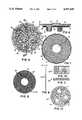
- FIG. 1is a cross-sectional view of a prior art patellar component which does not include any porous surface between the metal base and the polyethylene portion;
- FIG. 2is a perspective view of the top surface of a patellar component according to the present invention.
- FIG. 3is a bottom plan view of the patellar component of FIG. 2;
- FIG. 4is a cross sectional view of the patellar component taken along lines 4--4 of FIG. 3;
- FIG. 5is a bottom plan view of the patellar component of FIG. 2, without the polyethylene portion 3 included;
- FIG. 6is a cross-sectional view taken along lines 6-6 of FIG. 5;
- FIG. 7is a top plan view of the component of FIG. 5;
- FIG. 8is a plan view of the screen layer 30 of FIG. 7;
- FIG. 9is a side elevational view of the screen layer of FIG. 8;
- FIG. 10is an enlarged detail view of the screen layer taken at 10-10 of FIG. 8;
- FIG. 11is a side view of the screen layer of FIG. 10.
- FIG. 12is a plan view of the porous external layer 40 of FIG. 5.
- FIGS. 2-12illustrate a particularly advantageous embodiment of a prosthetic implant according to the present invention.
- the inventionwill be described with reference to a patellar prosthetic implant and is particularly suitable as such. However, it is understood that the principles of the invention may be suitable for other implants utilizing a polyethylene portion connected to a metal base, such as a tibial component, as well as others.
- the patellar prosthetic implant 1 of FIGS. 2-12includes a metal base 10 having an upper surface 11 and a lower surface 12.
- the implant 1further includes a layer of metallic wire screen 30 bonded to the upper surface 11 of the base 10.
- the screen 30includes a plurality of porous openings 35 therein.
- the implantfurther includes a polyethylene portion 3 molded about the upper surface 11 of the base 10.
- the polyethylene portion 3penetrates the porous openings in the screen 30 to enhance the securement of the polyethylene portion to the base 10.
- the screen 30is fully encapsulated between the metal base 10 and the polyethylene portion 3.
- the polyethylene portion 3includes a top surface 4 which may be any suitable articulating surface, such as that shown, which includes a central raised portion 5 and surrounding contact area 6.
- the metal base 10includes a peripheral edge 20 which includes a plurality of notches 19 spaced apart from each other around the peripheral edge 20.
- the notches 19provide interdigitation between the polyethylene portion 3 and the base 4, since the poly fills the notches 19. This helps resist rotational forces, and thus helps to further secure the poly portion 3 to the base 10.
- the screen layer 30extends or overhangs over at least a portion of the notches 19 as shown in FIGS. 5-7. The extension of the screen 30 over the notches 19 helps to prevent stress risers which could occur and cushions the forces seen at the notches 19.
- the upper surface 11 of the base 10further includes a raised portion 13 including an undercut ledge 14 thereabout.
- the raised portion 13does not include any screen 30 (or other porous material) thereon.
- the molded polyethylene portion 30thus extends under the undercut ledge 14 of the raised portion 13 to further enhance the securement of the poly portion 3 to the base 10.
- the raised portion 13 in the base 10supplies resistance to shear forces, as well as tensile forces, since it is undercut.
- the peripheral edge 20also further includes an undercut ledge 15 thereabout.
- the molded polyethylene portionextends under the undercut ledge 15 of the peripheral edge 20 to further enhance the securement of the poly portion 3 to the base 10.
- the implant 1may also include a layer of porous metallic material 40 bonded to the lower surface 12 of the base 10.
- the construction of the screen layer 30 on the upper surface 11is different from the construction of the porous metallic layer 40 on the lower surface 12.
- the layer 30is a thin screen layer in which the construction comprises uniformly arranged wires with uniformly spaced openings 35 therebetween the substantially uniform pattern of wires.
- a particularly advantageous weave patternis a "twill" weave which is shown in the detail of FIGS. 10-11.
- the twill weaveis a known weave pattern that goes under two wires/over two wires/under two wires/over two wires, etc. (as opposed to a standard weave which goes over/under/over/under, etc.
- the screen 30is bonded to the metal base 10 by sintering, or other suitable metallic bonding means.
- the metal wire screen 30is compressed to create "flats" (rather than rounded wire surfaces) to increase the contact area between the screen 30 and the metal base 10.
- the screenis also flattened so that stress risers are not introduced beneath the high load areas.
- the flattened screengreatly enhances the metallic bond strength between the screen 30 and base 10. Since there are many small bonds capturing and supporting the poly 3 (which is molded to the bonded base 10 and screen 30), regardless of where the load may be applied, this construction resists giving the poly the opportunity to flow radially at the plate interface. Since this local area of poly 3 beneath the load is held firmly, overall deformation of the poly 3 is significantly reduced, thereby enhancing the performance and integrity of the component.
- the porous layer 40 on the lower surface 12 of the base 10is a metal wire mesh member in which compressed wires are bonded together in a random arrangement with randomly spaced openings therebetween
- a particularly suitable type of randomly patterned wiresis a type such as that described in U.S. Pat. No. 3,906,550 to Rostoker et al. (mentioned above in Background section).
- This wireis prekinked and then molded or compressed into the desired shape which shape produces a porous layer such as 40 having a construction which includes randomly arranged and compressed wires and randomly spaced openings therebetween.
- the compressed wires of layer 40are bonded together and to the base by a suitable metallic bonding means such as sintering or diffusion bonding, thus metallurgically bonding the wires to each other at their points of contact and to the metal base at the points of contact with the base 10.
- This type of porous surface 40is particularly suitable for implantation into bone without the use of bone cement, so that the bone surfaces contacting the exposed porous surface, such as 40, will enable bone to grow into the porous surface to secure the implant to the bone (not shown) If used with bone cement, the bone cement can securely interlock into the porous surface 40.
- the construction for porous surface 40is particularly suitable for securing the implant 1 into the body, whereas the differing construction for the screen layer 30 is particularly suitable for securing the poly 3 to the metal base 10.
- the typical optimum size porous opening 35 in the screen 30is about 0.039 inches (1 mm), using a wire diameter of about 0.016 inches (0.4 mm).
- the wire diameter for the screen 30has been chosen to optimize the poly and metal bonding Larger wire diameters provide increased metal bond strength, but less poly bond strength, since the pore size and poly interlock would be reduced.
- the polyis molded so it flows completely into the openings 35.
- the typical size porous opening in the porous layer 40is about 0.015 inches (0.38 mm).
- the screen layer 30is thinner than the porous layer 40.
- the screen 30is very thin so the thickness of the poly portion can be optimized.
- the screen layermay suitably be about 0.016 to 0.025 inches (0.4 to 0.6 mm) thick as shown in FIG. 9 at 31, whereas the porous layer 40 may suitably be 0.039 to 0.079 inches (1 to 2 mm) to allow for ingrowth of bone or penetration of bone cement.
- the base 10may include a recessed portion 18 for the porous layer 40.
- the discrete screen 30includes an opening 32 therethrough as shown in FIG. 8 to allow the raised portion 13 to extend through the opening 32.
- the opening 32is large enough to provide a clearance or gap between the raised portion 13 and the screen 30 to allow the molded polyethylene portion to flow freely into and extend under the undercut ledge 14 of the raised portion 13.
- FIGS. 2-12shows a single raised portion 13, which is centrally located, with a corresponding single opening 32 in screen 30; however, it is understood that, although not shown, multiple raised portions and corresponding multiple openings in the screen could be utilized in alternate embodiments in keeping with the present invention.
- the notches 19 around the peripheral edge 20 of base 10may suitably be about 0.039 inches (1 mm) in thickness (52), about 0.079 inches (2 mm) in length (54) and about 0.039 inches (1 mm) in width (56).
- the screen 30overhangs the notches 19, as shown in FIGS. 5-7, with the screen 30 overhanging at least a portion of the notches 19, and in fact, substantially overhanging a majority of the length 54 and width 56 of the notches, although the screen may extend just barely short of the full width of the notches 19 as shown. Typically, the screen 30 would not extend beyond the width of the notches 19. It is understood that the extension is of a porous screen layer 30 with holes 35 throughout, thus still allowing the poly 3 to fill through the notches 19.
- This overhang of screen 30 over notches 19, as described,is considered an important feature, as it helps lessen the chance for stress risers in the design. Further, since the screen 30 substantially covers the metal base 10 to its peripheral edge 20 and overhangs the notches 19, and the metal base 10 extends nearly to the periphery of the entire implant 1, this helps provide support where the loads are highest.
- the patella implant 1, shown in FIGS. 2-12,may additionally include a plurality of posts 16 extending from base 10 for fixation and support.
- the 3-post design shownresists shear stresses and prevents toggling.
- the postsadditionally may include porous material 42 about the posts, similar to the porous material layer 40, with metallic cap portions 17 on the end of each post 16.
- the base 10 of the implant 1may be machined or cast or otherwise suitably manufactured out of any appropriate metal suitable for surgical implants, such as titanium or a titanium alloy.
- the wire screen 30 and porous wire layer 40may also be made from titanium or a titanium alloy.
- the porous screen 30 and porous layer 40are bonded metallurgically to the base 10 as previously described. It is noted that the screen 30 and the porous layer 40, including the porous material 42 about the posts, and the caps 17, may all be bonded to the base 10 in a single bonding operation in which these items are held together in a suitable bonding fixture (not shown).
- the poly portion 3which may suitably be ultra high molecular weight polyethylene, is then molded about the upper surface 11 and peripheral edge 20 of base 10 to fully encapsulate the screen 30 between the metal base 10 and the poly portion 3. It is understood that other suitable metal or non-metal implant materials may be utilized with the present invention, as appropriate. Any suitable manufacturing methods may be utilized.
- the internal construction of the patellar implant 1is designed to maintain the integrity and shape of the patella through dynamic knee activity
- the metal base 10extends nearly to the periphery of the overall implant 1 to provide support where the loads are high.
- indicia 80 and 82may be utilized on the end of posts 16, if desired.
- Indicia 80indicates the prosthesis size reference, while indicia 82 indicates the manufacturer's initial. Multiple, or other component sizes may be utilized, and thus the appropriate size reference may be referenced via the appropriate indicia.
- Other informationif needed, could be indicated in a similar manner. This information may be etched on or otherwise indicated in accordance with typical industry practice re the marking of implants.
- the prosthetic implant 1 of the present invention described hereinincludes a unique enhanced means of bonding or securely attaching a polyethylene portion to a metal base to provide a secure polyethylene/metal interlock therebetween. While this invention has been described and exemplified in terms of a particularly advantageous embodiment, those skilled in the art can appreciate that modifications can be made without departing from the spirit and scope of this invention.
Landscapes
- Health & Medical Sciences (AREA)
- Orthopedic Medicine & Surgery (AREA)
- Cardiology (AREA)
- Oral & Maxillofacial Surgery (AREA)
- Transplantation (AREA)
- Engineering & Computer Science (AREA)
- Biomedical Technology (AREA)
- Heart & Thoracic Surgery (AREA)
- Vascular Medicine (AREA)
- Life Sciences & Earth Sciences (AREA)
- Animal Behavior & Ethology (AREA)
- General Health & Medical Sciences (AREA)
- Public Health (AREA)
- Veterinary Medicine (AREA)
- Physical Education & Sports Medicine (AREA)
- Prostheses (AREA)
Abstract
Description
The present invention relates to a prosthetic implant device, and more particularly to such implants which include a polyethylene portion secured to a metal base. This invention is particularly suitable for use as a patellar prosthesis or a tibial prosthesis although it is not limited thereto.
Heretofore, various means have been used to provide secure attachment of a polyethylene implant portion to a metal base. U.S. Pat. No. 4,501,031 to McDaniel et al. discloses a metal base which includes notches about its peripheral edge to help secure a plastic bearing portion via molding to the base. U.S. Pat. No. 4,205,400 discloses a metal base which includes tapered holes therethrough which diverge away from the upper surface and a plastic bearing portion molded to the base and through the tapered holes to secure the plastic to the metal U.S. Pat. No. 3,506,982 includes ametal anchor 3 fixed into theplastic portion 4.
In addition, a metal-backed polyethylene patella known as the AMK Patella (described in a Depuy ad® in the July 1989 JBJS, p.68) utilizes a Porocoat porous coating on the upper surface of the metal base between the plastic and metal to lock the poly surface to the metal backing. This component also uses the Porocoat porous coating on the lower exposed surface of the base. The Porocoat coating consists of a plurality of small ball-shaped metallic particles as described by U.S. Pat. No. 3,855,638 to Pilliar.
The utilization of various porous materials to select exposed or outer surfaces of implants is well known to enhance to fixation of such outer surfaces to bone for bony ingrowth or, if a bone cement material is used for fixation, to more securely fix such outer surfaces to the bone cement. Other examples of various porous materials utilized on select outer surfaces of metal or poly implants are disclosed in U.S. Pat. Nos. 3,605,123 to Hahn; U.S. Pat. No. 3,906,550 to Rostoker et al.; U.S. Pat. No. 4,454,612 to McDaniel et al; U.S. Pat. No. 4,589,883 to Kenna; and 4,636,219 to Pratt et al. In addition, U.S. Pat. No. 4,479,271 to Bolesky et al. discloses a bottom base layer of porous fiber metal material, an intermediate metal reinforcing layer including at least one opening therein, and a top non-metal surface (such as polyethylene) which is molded to the base layer. The portion of the top polyethylene layer that is in contact with the base layer penetrates into the interstices of the porous metal material, hence securing the non-metal layer to the porous metal base layer.
U.S. Pat. No. 3,720,996 to Tschermak discloses a method of producing a tight connection between a synthetic body and a metal body which comprises inserting a porous sintered metal body into the synthetic body and then pressing them together so the plastic of the synthetic body penetrates the pores of the sintered metal body, and then connecting an additional metal body to the exposed portion of the porous sintered metal body.
U.S Pat. No. 4,007,494 to Sauer discloses a bone cap comprising a porous body adapted for bone ingrowth that is partially covered by a coating of non-porous biocompatible material such as polyethylene.
U.S. Pat. No. 4,213,816 to Morris discloses a method for bonding a porous coating of polymeric material to a rigid structural member that employs an intermediate substrate layer of material that is chemically compatible with the polymeric material, but has a lower melting temperature so as to flow into the pores of the polymeric material.
In addition, it is noted that it is known in the art of implants to separately manufacture a polyethylene portion and a metal portion and subsequently attach them by various mechanical means of locking. Often these separately manufactured poly and metal components enable the poly portion to be removably secured to the metal base. Examples of such devices are disclosed in U.S. Pat. Nos 4,795,468 to Hodorek et al. and U.S. Pat. No. 4,207,627 to Cloutier. However, it is not the intention of the present invention to address such removable attachment features, but rather to address the permanent interlock of a plastic portion to a metal portion.
A principal of the invention is to provide a metal-backed prosthetic implant which provides an enhanced, secure attachment of the polyethylene portion to the metal base.
Another object of the invention is to provide such an attachment which helps to lessen stress risers in the implant.
A further object of the invention is to optimize the attachment of the polyethylene portion to the metal base by utilizing a porous screen layer therebetween, while optimizing the outer exposed attachment surface of the metal base with a porous surface different from that of the screen layer.
A still further object of the invention is to provide means for enhancing the attachment of the poly to the metal base which is simple to manufacture, yet highly effective.
This invention comprises a prosthetic implant having a metal base with a layer of metallic wire screen bonded to the upper surface of the base, and further having a polyethylene portion molded about the upper surface of the base. The polyethylene portion penetrates the porous openings in the screen to enhance the securement of the polyethylene portion to the base. The screen is fully encapsulated between the metal base and the polyethylene portion. The base further includes a plurality of notches spaced around the peripheral edge. The screen layer overhangs over at least a portion of the notches. In addition, the lower surface of the base includes a porous metallic layer providing an exposed porous surface. The construction of the screen layer on the upper surface of the base is different from the construction of the porous layer on the lower surface.
These features and objects of the invention as well as others, will become apparent to those skilled in the art by referring to the accompanying drawings:
FIG. 1 is a cross-sectional view of a prior art patellar component which does not include any porous surface between the metal base and the polyethylene portion;
FIG. 2 is a perspective view of the top surface of a patellar component according to the present invention;
FIG. 3 is a bottom plan view of the patellar component of FIG. 2;
FIG. 4 is a cross sectional view of the patellar component taken alonglines 4--4 of FIG. 3;
FIG. 5 is a bottom plan view of the patellar component of FIG. 2, without thepolyethylene portion 3 included;
FIG. 6 is a cross-sectional view taken along lines 6-6 of FIG. 5;
FIG. 7 is a top plan view of the component of FIG. 5;
FIG. 8 is a plan view of thescreen layer 30 of FIG. 7;
FIG. 9 is a side elevational view of the screen layer of FIG. 8;
FIG. 10 is an enlarged detail view of the screen layer taken at 10-10 of FIG. 8;
FIG. 11 is a side view of the screen layer of FIG. 10; and
FIG. 12 is a plan view of the porousexternal layer 40 of FIG. 5.
FIGS. 2-12 illustrate a particularly advantageous embodiment of a prosthetic implant according to the present invention. The invention will be described with reference to a patellar prosthetic implant and is particularly suitable as such. However, it is understood that the principles of the invention may be suitable for other implants utilizing a polyethylene portion connected to a metal base, such as a tibial component, as well as others.
The patellar prosthetic implant 1 of FIGS. 2-12 includes ametal base 10 having an upper surface 11 and alower surface 12. The implant 1 further includes a layer ofmetallic wire screen 30 bonded to the upper surface 11 of thebase 10. Thescreen 30 includes a plurality ofporous openings 35 therein. The implant further includes apolyethylene portion 3 molded about the upper surface 11 of thebase 10. Thepolyethylene portion 3 penetrates the porous openings in thescreen 30 to enhance the securement of the polyethylene portion to thebase 10. Thescreen 30 is fully encapsulated between themetal base 10 and thepolyethylene portion 3. Thepolyethylene portion 3 includes atop surface 4 which may be any suitable articulating surface, such as that shown, which includes a central raisedportion 5 and surroundingcontact area 6.
Themetal base 10 includes aperipheral edge 20 which includes a plurality ofnotches 19 spaced apart from each other around theperipheral edge 20. Thenotches 19 provide interdigitation between thepolyethylene portion 3 and thebase 4, since the poly fills thenotches 19. This helps resist rotational forces, and thus helps to further secure thepoly portion 3 to thebase 10. Thescreen layer 30 extends or overhangs over at least a portion of thenotches 19 as shown in FIGS. 5-7. The extension of thescreen 30 over thenotches 19 helps to prevent stress risers which could occur and cushions the forces seen at thenotches 19.
The upper surface 11 of the base 10 further includes a raisedportion 13 including an undercutledge 14 thereabout. The raisedportion 13 does not include any screen 30 (or other porous material) thereon. The moldedpolyethylene portion 30 thus extends under the undercutledge 14 of the raisedportion 13 to further enhance the securement of thepoly portion 3 to thebase 10. The raisedportion 13 in the base 10 supplies resistance to shear forces, as well as tensile forces, since it is undercut.
Theperipheral edge 20 also further includes an undercutledge 15 thereabout. The molded polyethylene portion extends under the undercutledge 15 of theperipheral edge 20 to further enhance the securement of thepoly portion 3 to thebase 10.
The implant 1 may also include a layer of porousmetallic material 40 bonded to thelower surface 12 of thebase 10. The construction of thescreen layer 30 on the upper surface 11 is different from the construction of the porousmetallic layer 40 on thelower surface 12. Thelayer 30 is a thin screen layer in which the construction comprises uniformly arranged wires with uniformly spacedopenings 35 therebetween the substantially uniform pattern of wires. Although other substantially uniform patterns of wire screen may be utilized, a particularly advantageous weave pattern is a "twill" weave which is shown in the detail of FIGS. 10-11. The twill weave is a known weave pattern that goes under two wires/over two wires/under two wires/over two wires, etc. (as opposed to a standard weave which goes over/under/over/under, etc. With the twill weave, as shown in FIGS. 10-11, each shute wire typically passes over two warp wires and under two, producing square openings. Twill weave can be made from a variety of diameter wires, thereby obtaining varied requirements for strength, density, or corrosion resistance. The twill weave is advantageous for use with the present invention because it provides increased area for the poly to "reach" or flow beneath the wire diameter and supply interlock and tensile resistance.
Thescreen 30 is bonded to themetal base 10 by sintering, or other suitable metallic bonding means. However, before sintering, themetal wire screen 30 is compressed to create "flats" (rather than rounded wire surfaces) to increase the contact area between thescreen 30 and themetal base 10. The screen is also flattened so that stress risers are not introduced beneath the high load areas. The flattened screen greatly enhances the metallic bond strength between thescreen 30 andbase 10. Since there are many small bonds capturing and supporting the poly 3 (which is molded to the bondedbase 10 and screen 30), regardless of where the load may be applied, this construction resists giving the poly the opportunity to flow radially at the plate interface. Since this local area ofpoly 3 beneath the load is held firmly, overall deformation of thepoly 3 is significantly reduced, thereby enhancing the performance and integrity of the component.
In contrast to the substantially uniform wire pattern of thescreen 30, theporous layer 40 on thelower surface 12 of thebase 10 is a metal wire mesh member in which compressed wires are bonded together in a random arrangement with randomly spaced openings therebetween A particularly suitable type of randomly patterned wires is a type such as that described in U.S. Pat. No. 3,906,550 to Rostoker et al. (mentioned above in Background section). This wire is prekinked and then molded or compressed into the desired shape which shape produces a porous layer such as 40 having a construction which includes randomly arranged and compressed wires and randomly spaced openings therebetween. The compressed wires oflayer 40 are bonded together and to the base by a suitable metallic bonding means such as sintering or diffusion bonding, thus metallurgically bonding the wires to each other at their points of contact and to the metal base at the points of contact with thebase 10. This type ofporous surface 40 is particularly suitable for implantation into bone without the use of bone cement, so that the bone surfaces contacting the exposed porous surface, such as 40, will enable bone to grow into the porous surface to secure the implant to the bone (not shown) If used with bone cement, the bone cement can securely interlock into theporous surface 40.
Thus, the construction forporous surface 40 is particularly suitable for securing the implant 1 into the body, whereas the differing construction for thescreen layer 30 is particularly suitable for securing thepoly 3 to themetal base 10. The typical optimum sizeporous opening 35 in thescreen 30 is about 0.039 inches (1 mm), using a wire diameter of about 0.016 inches (0.4 mm). The wire diameter for thescreen 30 has been chosen to optimize the poly and metal bonding Larger wire diameters provide increased metal bond strength, but less poly bond strength, since the pore size and poly interlock would be reduced. The poly is molded so it flows completely into theopenings 35. The typical size porous opening in theporous layer 40 is about 0.015 inches (0.38 mm).
Thescreen layer 30 is thinner than theporous layer 40. Thescreen 30 is very thin so the thickness of the poly portion can be optimized. For example, the screen layer may suitably be about 0.016 to 0.025 inches (0.4 to 0.6 mm) thick as shown in FIG. 9 at 31, whereas theporous layer 40 may suitably be 0.039 to 0.079 inches (1 to 2 mm) to allow for ingrowth of bone or penetration of bone cement. The base 10 may include a recessedportion 18 for theporous layer 40.
Thediscrete screen 30 includes anopening 32 therethrough as shown in FIG. 8 to allow the raisedportion 13 to extend through theopening 32. Theopening 32 is large enough to provide a clearance or gap between the raisedportion 13 and thescreen 30 to allow the molded polyethylene portion to flow freely into and extend under the undercutledge 14 of the raisedportion 13. It is noted that the embodiment shown in FIGS. 2-12 shows a single raisedportion 13, which is centrally located, with a correspondingsingle opening 32 inscreen 30; however, it is understood that, although not shown, multiple raised portions and corresponding multiple openings in the screen could be utilized in alternate embodiments in keeping with the present invention.
Thenotches 19 around theperipheral edge 20 ofbase 10 may suitably be about 0.039 inches (1 mm) in thickness (52), about 0.079 inches (2 mm) in length (54) and about 0.039 inches (1 mm) in width (56). Thescreen 30 overhangs thenotches 19, as shown in FIGS. 5-7, with thescreen 30 overhanging at least a portion of thenotches 19, and in fact, substantially overhanging a majority of thelength 54 and width 56 of the notches, although the screen may extend just barely short of the full width of thenotches 19 as shown. Typically, thescreen 30 would not extend beyond the width of thenotches 19. It is understood that the extension is of aporous screen layer 30 withholes 35 throughout, thus still allowing thepoly 3 to fill through thenotches 19. This overhang ofscreen 30 overnotches 19, as described, is considered an important feature, as it helps lessen the chance for stress risers in the design. Further, since thescreen 30 substantially covers themetal base 10 to itsperipheral edge 20 and overhangs thenotches 19, and themetal base 10 extends nearly to the periphery of the entire implant 1, this helps provide support where the loads are highest.
The patella implant 1, shown in FIGS. 2-12, may additionally include a plurality ofposts 16 extending frombase 10 for fixation and support. The 3-post design shown resists shear stresses and prevents toggling. The posts additionally may includeporous material 42 about the posts, similar to theporous material layer 40, withmetallic cap portions 17 on the end of eachpost 16.
Thebase 10 of the implant 1 may be machined or cast or otherwise suitably manufactured out of any appropriate metal suitable for surgical implants, such as titanium or a titanium alloy. Thewire screen 30 andporous wire layer 40 may also be made from titanium or a titanium alloy. Theporous screen 30 andporous layer 40 are bonded metallurgically to the base 10 as previously described. It is noted that thescreen 30 and theporous layer 40, including theporous material 42 about the posts, and thecaps 17, may all be bonded to the base 10 in a single bonding operation in which these items are held together in a suitable bonding fixture (not shown). Thepoly portion 3, which may suitably be ultra high molecular weight polyethylene, is then molded about the upper surface 11 andperipheral edge 20 ofbase 10 to fully encapsulate thescreen 30 between themetal base 10 and thepoly portion 3. It is understood that other suitable metal or non-metal implant materials may be utilized with the present invention, as appropriate. Any suitable manufacturing methods may be utilized.
The internal construction of the patellar implant 1 is designed to maintain the integrity and shape of the patella through dynamic knee activity Themetal base 10 extends nearly to the periphery of the overall implant 1 to provide support where the loads are high.
With reference to FIG. 5, it is noted thatindicia posts 16, if desired.Indicia 80, as shown, indicates the prosthesis size reference, whileindicia 82 indicates the manufacturer's initial. Multiple, or other component sizes may be utilized, and thus the appropriate size reference may be referenced via the appropriate indicia. Other information, if needed, could be indicated in a similar manner. This information may be etched on or otherwise indicated in accordance with typical industry practice re the marking of implants.
The prosthetic implant 1 of the present invention described herein includes a unique enhanced means of bonding or securely attaching a polyethylene portion to a metal base to provide a secure polyethylene/metal interlock therebetween. While this invention has been described and exemplified in terms of a particularly advantageous embodiment, those skilled in the art can appreciate that modifications can be made without departing from the spirit and scope of this invention.
Claims (12)
1. A prosthetic implant having a metal base including an upper surface and a lower surface, the implant further including a layer of metallic wire screen bonded to the upper surface of the metal base, the screen having porous openings therein, and the implant further including a polyethylene portion molded about the upper surface of the base, the polyethylene portion penetrating the porous openings in the screen to enhance the securement of the polyethylene portion to the base and wherein the screen is fully encapsulated between the metal base and the polyethylene portion, and wherein the metal base includes a peripheral edge which includes a plurality of notches spaced apart from each other around the peripheral edge, and wherein the screen layer extends and overhangs over at least a portion of the notches.
2. The implant of claim 2 wherein the lower surface includes a layer of porous metallic material bonded thereto and wherein the construction of the screen layer on the upper surface is different from the construction of the porous metallic layer on the lower surface.
3. A prosthetic implant having a metal base including an upper surface and a lower surface, the implant further including a layer of metallic wire screen bonded to the upper surface of the metal base, the screen having porous openings therein, and the implant further including a polyethylene portion molded about the upper surface of the base, the polyethylene portion penetrating the porous openings in the screen to enhance the securement of the polyethylene portion to the base and wherein the screen is fully encapsulated between the metal base and the polyethylene portion, and wherein the upper surface further includes a raised portion including an undercut ledge thereabouts, and wherein the raised portion does not include any screen thereon, and wherein the molded polyethylene portion extends under the undercut ledge of the raised portion to further enhance the securement of the polyethylene portion to the base.
4. A prosthetic implant having a metal base including an upper surface and a lower surface, the implant further including a layer of metallic wire screen bonded to the upper surface of the metal base, the screen having porous openings therein, and the implant further including a polyethylene portion molded about the upper surface of the base, the polyethylene portion penetrating the porous openings in the screen to enhance the securement of the polyethylene portion to the base and wherein the screen is fully encapsulated between the metal base and the polyethylene portion, and wherein the upper surface further includes a raised portion including an undercut ledge thereabout, and wherein the raised portion does not include any screen thereon, and wherein the molded polyethylene portion extends under the undercut ledge of the raised portion to further enhance the securement of the polyethylene portion to the base, and wherein the peripheral edge further includes an undercut ledge thereabout, and wherein the molded polyethylene portion extends under the undercut ledge of the peripheral edge to further enhance the securement of the polyethylene portion to the base.
5. The implant of claim 3 wherein the screen includes an opening means therethrough to allow the raised portion to extend through the opening means and wherein the opening means is large enough to provide a clearance or gap between the raised portion and the screen to allow the molded polyethylene portion to fully extend under the undercut ledge of the raised portion.
6. The implant of claim 1 wherein the screen is uniformly constructed using a twill weave.
7. The implant of claim 1 wherein the screen is compressed to flatten the screen and increase the contact area between the screen and the upper surface of the base.
8. A prosthetic implant having a metal base including an upper surface and a lower surface, the implant further including a first porous layer of one construction bonded to the upper surface and a second porous layer of a second construction different from the one construction, the second layer bonded to the lower surface, and the implant further including a polyethylene portion molded about the upper surface of the metal base, the polyethylene penetrating the first porous layer to enhance the securement of the polyethylene portion to the base and wherein the first porous layer is fully encapsulated between the metal base and the polyethylene portion, and wherein the second porous layer provides an exposed porous surface.
9. The implant of claim 8 wherein the one construction of the first porous layer is a screen member having substantially uniformly arranged pattern of wires and substantially uniformly spaced openings therebetween and wherein the second construction of the second porous layer is a mesh member having randomly arranged and compressed wires and randomly spaced openings therebetween.
10. The implant of claim 8 wherein the first porous layer is thinner than the second porous layer.
11. A prosthetic implant having a metal base including an upper surface and a lower surface, the implant further including a porous metallic layer bonded to the upper surface of the metal base, and the implant further including a polyethylene portion molded about the upper surface of the base, the polyethylene portion penetrating the porous layer to enhance the securement of the polyethylene portion to the base and wherein the porous layer is fully encapsulated between the metal base and the polyethylene portion, and wherein the metal base includes a peripheral edge which includes a plurality of notches spaced apart from each other around the peripheral edge, and wherein the porous layer extends and overhangs over at least a portion of the notches.
12. The implant of claim 11 wherein the notches have a width and a length and the porous layer extends over a majority of the width and length of the notches, but does not extend beyond the width of the notches.
Priority Applications (1)
| Application Number | Priority Date | Filing Date | Title |
|---|---|---|---|
| US07/447,757US4997445A (en) | 1989-12-08 | 1989-12-08 | Metal-backed prosthetic implant with enhanced bonding of polyethylene portion to metal base |
Applications Claiming Priority (1)
| Application Number | Priority Date | Filing Date | Title |
|---|---|---|---|
| US07/447,757US4997445A (en) | 1989-12-08 | 1989-12-08 | Metal-backed prosthetic implant with enhanced bonding of polyethylene portion to metal base |
Publications (1)
| Publication Number | Publication Date |
|---|---|
| US4997445Atrue US4997445A (en) | 1991-03-05 |
Family
ID=23777627
Family Applications (1)
| Application Number | Title | Priority Date | Filing Date |
|---|---|---|---|
| US07/447,757Expired - LifetimeUS4997445A (en) | 1989-12-08 | 1989-12-08 | Metal-backed prosthetic implant with enhanced bonding of polyethylene portion to metal base |
Country Status (1)
| Country | Link |
|---|---|
| US (1) | US4997445A (en) |
Cited By (97)
| Publication number | Priority date | Publication date | Assignee | Title |
|---|---|---|---|---|
| EP0522999A1 (en)* | 1991-07-05 | 1993-01-13 | SULZER Medizinaltechnik AG | Patella prosthesis |
| EP0526682A1 (en)* | 1991-08-07 | 1993-02-10 | Oscobal Ag | Endoprosthesis with a metal wire mesh |
| EP0576103A1 (en)* | 1992-06-26 | 1993-12-29 | ESKA Implants GmbH & Co. | Implant as a replacement for a rear patella part |
| US5387243A (en)* | 1992-11-23 | 1995-02-07 | Zimmer, Inc. | Method for converting a cementable implant to a press fit implant |
| WO1995033423A1 (en)* | 1994-06-02 | 1995-12-14 | Incavo Stephen J | Hybrid tibial tray knee prosthesis |
| EP0705580A1 (en)* | 1994-10-05 | 1996-04-10 | Howmedica International Inc. | Metal backing for inclusion in the manufacture of a prosthetic component |
| FR2727308A1 (en)* | 1994-11-28 | 1996-05-31 | Prothese Dentaire Chibrac Sa | JOINT IMPLANT |
| US5723011A (en)* | 1992-12-21 | 1998-03-03 | Zimmer, Inc. | Prosthetic implant and method of making same |
| EP0829243A1 (en)* | 1996-09-12 | 1998-03-18 | Waldemar Link (GmbH & Co.) | Joint endoprosthesis |
| US6280476B1 (en)* | 1998-10-16 | 2001-08-28 | Biomet Inc. | Hip joint prosthesis convertible in vivo to a modular prosthesis |
| US6500208B1 (en) | 1998-10-16 | 2002-12-31 | Biomet, Inc. | Nonmodular joint prosthesis convertible in vivo to a modular prosthesis |
| US20030009231A1 (en)* | 2001-06-30 | 2003-01-09 | Gundlapalli Rama Rao V. | Joint replacement prosthesis component with non linear insert |
| US20030006530A1 (en)* | 2001-06-29 | 2003-01-09 | Gundlapalli Rama Rao V. | Joint prosthesis molding method and die for preforming the same |
| US20030069605A1 (en)* | 1990-06-28 | 2003-04-10 | Bonutti Peter M. | Surgical devices containing a heat bondable material with a therapeutic agent |
| US6797007B1 (en)* | 1998-03-25 | 2004-09-28 | Ceramtec Ag Innovative Ceramic Engineering | Press fit connection between prosthesis components of joint prostheses |
| US20040220616A1 (en)* | 2000-03-13 | 2004-11-04 | Bonutti Peter M. | Method and device for securing body tissue |
| US6972039B2 (en) | 1999-03-01 | 2005-12-06 | Biomet, Inc. | Floating bearing knee joint prosthesis with a fixed tibial post |
| US20060241781A1 (en)* | 2005-04-21 | 2006-10-26 | Biomet Manufacturing Corp. | Method and apparatus for use of porous implants |
| US20060241776A1 (en)* | 2005-04-21 | 2006-10-26 | Biomet Manufacturing Corp. | Method and apparatus for use of porous implants |
| US7128753B1 (en) | 1990-06-28 | 2006-10-31 | Bonutti Peter M | Surgical devices having a polymeric material with a therapeutic agent and methods for making same |
| US20070142914A1 (en)* | 2005-12-06 | 2007-06-21 | Eric Jones | Laser-produced porous surface |
| US20070173948A1 (en)* | 2005-04-21 | 2007-07-26 | Biomet Manufacturing Corp. | Porous metal cup with cobalt bearing surface |
| US20070196230A1 (en)* | 2006-02-17 | 2007-08-23 | Biomet Manufacturing Corp. | Method and apparatus for forming porous metal implants |
| US20080027556A1 (en)* | 2006-07-10 | 2008-01-31 | Biomet Manufacturing Corp. | Compliant tibial component |
| US20080039873A1 (en)* | 2004-03-09 | 2008-02-14 | Marctec, Llc. | Method and device for securing body tissue |
| US20080065225A1 (en)* | 2005-02-18 | 2008-03-13 | Wasielewski Ray C | Smart joint implant sensors |
| US20080140212A1 (en)* | 2001-05-15 | 2008-06-12 | Robert Metzger | Elongated femoral component |
| US20080140116A1 (en)* | 1999-08-09 | 2008-06-12 | Bonutti Peter M | Method and apparatus for securing tissue |
| US20080147187A1 (en)* | 2005-04-21 | 2008-06-19 | Biomet Manufacturing Corp. | Method And Apparatus For Use Of Porous Implants |
| US20080154233A1 (en)* | 2006-12-20 | 2008-06-26 | Zimmer Orthobiologics, Inc. | Apparatus for delivering a biocompatible material to a surgical site and method of using same |
| US20080243259A1 (en)* | 2007-03-30 | 2008-10-02 | Lee Jordan S | Mobile bearing insert having offset dwell point |
| US20080243262A1 (en)* | 2007-03-30 | 2008-10-02 | Lee Jordan S | Mobile bearing assembly |
| US20080243260A1 (en)* | 2007-03-30 | 2008-10-02 | Lee Jordan S | Mobile bearing assembly having a non-planar interface |
| US20080243261A1 (en)* | 2007-03-30 | 2008-10-02 | Wyss Joseph G | Mobile bearing assembly having a closed track |
| US20080243263A1 (en)* | 2007-03-30 | 2008-10-02 | Lee Jordan S | Mobile bearing assembly having multiple articulation interfaces |
| US20090012629A1 (en)* | 2007-04-12 | 2009-01-08 | Isto Technologies, Inc. | Compositions and methods for tissue repair |
| US20090084491A1 (en)* | 2007-09-25 | 2009-04-02 | Biomet Manufacturing Corp. | Cementless Tibial Tray |
| US20090138019A1 (en)* | 2003-04-08 | 2009-05-28 | Zimmer, Inc. | Use of micro and miniature position sensing devices for use in tka and tha |
| US20090143867A1 (en)* | 2005-08-26 | 2009-06-04 | Isto Technologies, Inc. | Implants and Methods for Repair, Replacement and Treatment of Disease |
| US20090163938A1 (en)* | 2003-04-30 | 2009-06-25 | Bonutti Peter M | Tissue fastener and methods for using same |
| US20090240336A1 (en)* | 2006-03-22 | 2009-09-24 | Ascension Orthopedics, Inc. | Prosthetic implant and assembly method |
| US20090299228A1 (en)* | 2008-06-02 | 2009-12-03 | Zimmer, Inc. | Implant sensors |
| EP2153800A1 (en)* | 2008-08-11 | 2010-02-17 | Alfred Ernst Buck | Artificial joint |
| US20100168857A1 (en)* | 2008-05-30 | 2010-07-01 | Edwin Burton Hatch | Flexibly compliant ceramic prosthetic meniscus for the replacement of damaged cartilage in orthopedic surgical repair or reconstruction of hip, knee, ankle, shoulder, elbow. wrist and other anatomical joints |
| US7854750B2 (en) | 2002-08-27 | 2010-12-21 | P Tech, Llc. | Apparatus and method for securing a suture |
| US20110009913A1 (en)* | 2008-02-06 | 2011-01-13 | Maria Del Carmen Navas | Orbit distractor |
| US7879072B2 (en) | 1997-08-01 | 2011-02-01 | P Tech, Llc. | Method for implanting a flowable fastener |
| US7967820B2 (en) | 2006-02-07 | 2011-06-28 | P Tech, Llc. | Methods and devices for trauma welding |
| US20110208316A1 (en)* | 2010-02-19 | 2011-08-25 | Biomet Manufacturing Corp. | Latent mobile bearing for prosthetic device |
| US8021432B2 (en) | 2005-12-05 | 2011-09-20 | Biomet Manufacturing Corp. | Apparatus for use of porous implants |
| US8123814B2 (en) | 2001-02-23 | 2012-02-28 | Biomet Manufacturing Corp. | Method and appartus for acetabular reconstruction |
| CN102727327A (en)* | 2012-05-24 | 2012-10-17 | 上海交通大学医学院附属第九人民医院 | Artificial knee joint prosthesis |
| US8496657B2 (en) | 2006-02-07 | 2013-07-30 | P Tech, Llc. | Methods for utilizing vibratory energy to weld, stake and/or remove implants |
| US8497121B2 (en) | 2006-12-20 | 2013-07-30 | Zimmer Orthobiologics, Inc. | Method of obtaining viable small tissue particles and use for tissue repair |
| US8518433B2 (en) | 2003-12-11 | 2013-08-27 | Zimmer, Inc. | Method of treating an osteochondral defect |
| US8617185B2 (en) | 2007-02-13 | 2013-12-31 | P Tech, Llc. | Fixation device |
| US8747439B2 (en) | 2000-03-13 | 2014-06-10 | P Tech, Llc | Method of using ultrasonic vibration to secure body tissue with fastening element |
| US8808329B2 (en) | 1998-02-06 | 2014-08-19 | Bonutti Skeletal Innovations Llc | Apparatus and method for securing a portion of a body |
| US8814902B2 (en) | 2000-05-03 | 2014-08-26 | Bonutti Skeletal Innovations Llc | Method of securing body tissue |
| US8845699B2 (en) | 1999-08-09 | 2014-09-30 | Bonutti Skeletal Innovations Llc | Method of securing tissue |
| US8845687B2 (en) | 1996-08-19 | 2014-09-30 | Bonutti Skeletal Innovations Llc | Anchor for securing a suture |
| US9089323B2 (en) | 2005-02-22 | 2015-07-28 | P Tech, Llc | Device and method for securing body tissue |
| CN104825254A (en)* | 2015-05-11 | 2015-08-12 | 北京爱康宜诚医疗器材股份有限公司 | Prosthesis part |
| US9135374B2 (en) | 2012-04-06 | 2015-09-15 | Howmedica Osteonics Corp. | Surface modified unit cell lattice structures for optimized secure freeform fabrication |
| US9138222B2 (en) | 2000-03-13 | 2015-09-22 | P Tech, Llc | Method and device for securing body tissue |
| US9149281B2 (en) | 2002-03-20 | 2015-10-06 | P Tech, Llc | Robotic system for engaging a fastener with body tissue |
| US9173647B2 (en) | 2004-10-26 | 2015-11-03 | P Tech, Llc | Tissue fixation system |
| US9180010B2 (en) | 2012-04-06 | 2015-11-10 | Howmedica Osteonics Corp. | Surface modified unit cell lattice structures for optimized secure freeform fabrication |
| US9226828B2 (en) | 2004-10-26 | 2016-01-05 | P Tech, Llc | Devices and methods for stabilizing tissue and implants |
| US9271766B2 (en) | 2004-10-26 | 2016-03-01 | P Tech, Llc | Devices and methods for stabilizing tissue and implants |
| US9439642B2 (en) | 2006-02-07 | 2016-09-13 | P Tech, Llc | Methods and devices for utilizing bondable materials |
| US9463012B2 (en) | 2004-10-26 | 2016-10-11 | P Tech, Llc | Apparatus for guiding and positioning an implant |
| US20170071749A1 (en)* | 2012-03-27 | 2017-03-16 | DePuy Synthes Products, Inc. | Glenoid defect-filling component |
| US9770238B2 (en) | 2001-12-03 | 2017-09-26 | P Tech, Llc | Magnetic positioning apparatus |
| US9949837B2 (en) | 2013-03-07 | 2018-04-24 | Howmedica Osteonics Corp. | Partially porous bone implant keel |
| US10058393B2 (en) | 2015-10-21 | 2018-08-28 | P Tech, Llc | Systems and methods for navigation and visualization |
| US10076377B2 (en) | 2013-01-05 | 2018-09-18 | P Tech, Llc | Fixation systems and methods |
| US10167447B2 (en) | 2012-12-21 | 2019-01-01 | Zimmer, Inc. | Supports and methods for promoting integration of cartilage tissue explants |
| US10596660B2 (en) | 2015-12-15 | 2020-03-24 | Howmedica Osteonics Corp. | Porous structures produced by additive layer manufacturing |
| CN111449806A (en)* | 2019-12-30 | 2020-07-28 | 雅博尼西医疗科技(苏州)有限公司 | Connection structure of porous surface structure and substrate, preparation method and prosthesis |
| US10888362B2 (en) | 2017-11-03 | 2021-01-12 | Howmedica Osteonics Corp. | Flexible construct for femoral reconstruction |
| US10893948B2 (en) | 2017-11-02 | 2021-01-19 | Howmedica Osteonics Corp. | Rotary arc patella articulating geometry |
| US11155073B2 (en) | 2002-11-08 | 2021-10-26 | Howmedica Osteonics Corp. | Laser-produced porous surface |
| US11246638B2 (en) | 2006-05-03 | 2022-02-15 | P Tech, Llc | Methods and devices for utilizing bondable materials |
| US11253296B2 (en) | 2006-02-07 | 2022-02-22 | P Tech, Llc | Methods and devices for intracorporeal bonding of implants with thermal energy |
| US11278412B2 (en)* | 2018-03-30 | 2022-03-22 | Depuy Ireland Unlimited Company | Hybrid fixation features for three-dimensional porous structures for bone ingrowth and methods for producing |
| US11278331B2 (en) | 2006-02-07 | 2022-03-22 | P Tech Llc | Method and devices for intracorporeal bonding of implants with thermal energy |
| US11298747B2 (en) | 2017-05-18 | 2022-04-12 | Howmedica Osteonics Corp. | High fatigue strength porous structure |
| US11357635B2 (en) | 2019-12-17 | 2022-06-14 | Depuy Ireland Unlimited Company | Metal-backed patella component of an orthopaedic knee prosthesis and associated method of making the same |
| US11364123B2 (en) | 2018-03-26 | 2022-06-21 | Depuy Ireland Unlimited Company | Three-dimensional porous structures for bone ingrowth and methods for producing |
| US11400181B2 (en) | 2017-06-09 | 2022-08-02 | Howmedica Osteonics Corp. | Polymer interlock support structure and method of manufacture thereof |
| JP2022140379A (en)* | 2021-03-10 | 2022-09-26 | グローバス メディカル インコーポレイティッド | Systems and methods for knee arthroplasty |
| US11517438B2 (en) | 2019-09-25 | 2022-12-06 | Depuy Ireland Unlimited Company | Three-dimensional porous structures for bone ingrowth and methods for producing |
| US11628517B2 (en) | 2017-06-15 | 2023-04-18 | Howmedica Osteonics Corp. | Porous structures produced by additive layer manufacturing |
| US11844697B2 (en) | 2020-09-03 | 2023-12-19 | Globus Medical, Inc. | Systems and methods for knee arthroplasty |
| US11890200B2 (en) | 2018-03-30 | 2024-02-06 | Depuy Ireland Unlimited Company | Surface textures for three-dimensional porous structures for bone ingrowth and methods for producing |
| US12226317B2 (en) | 2019-12-17 | 2025-02-18 | Depuy Ireland Unlimited Company | Metal-backed tibial component of an orthopaedic knee prosthesis and associated method of making the same |
Citations (18)
| Publication number | Priority date | Publication date | Assignee | Title |
|---|---|---|---|---|
| US3506982A (en)* | 1965-06-21 | 1970-04-21 | Cleveland Clinic | Endoprosthetic joints |
| US3605123A (en)* | 1969-04-29 | 1971-09-20 | Melpar Inc | Bone implant |
| US3720996A (en)* | 1968-10-16 | 1973-03-20 | Siemens Ag | Process for the manufacture of a rigid connection between a synthetic body and a metal body |
| US3855638A (en)* | 1970-06-04 | 1974-12-24 | Ontario Research Foundation | Surgical prosthetic device with porous metal coating |
| US3906550A (en)* | 1973-12-27 | 1975-09-23 | William Rostoker | Prosthetic device having a porous fiber metal structure |
| US4007494A (en)* | 1975-04-11 | 1977-02-15 | Glasrock Products, Inc. | Bone cap |
| US4205400A (en)* | 1978-12-04 | 1980-06-03 | Zimmer Usa, Inc. | Metallo-polymeric prosthesis with cavitied interconnection |
| US4207627A (en)* | 1979-01-18 | 1980-06-17 | Cloutier Jean Marie | Knee prosthesis |
| US4213816A (en)* | 1978-06-12 | 1980-07-22 | Glasrock Products, Inc. | Method for bonding porous coating to rigid structural member |
| GB2059267A (en)* | 1979-09-28 | 1981-04-23 | Leuven Res & Dev Vzw | Compound material for prosthetic devices |
| US4454612A (en)* | 1980-05-07 | 1984-06-19 | Biomet, Inc. | Prosthesis formation having solid and porous polymeric components |
| US4479271A (en)* | 1981-10-26 | 1984-10-30 | Zimmer, Inc. | Prosthetic device adapted to promote bone/tissue ingrowth |
| US4501031A (en)* | 1981-01-22 | 1985-02-26 | Zimmer, Inc. | Metal and plastic composite tibial component for knee joint |
| US4589883A (en)* | 1983-06-06 | 1986-05-20 | Pfizer Hospital Products Group, Inc. | Femoral hip prosthesis |
| US4636219A (en)* | 1985-12-05 | 1987-01-13 | Techmedica, Inc. | Prosthesis device fabrication |
| US4718916A (en)* | 1985-06-12 | 1988-01-12 | Sulzer Brothers Ltd. | Femur head prosthesis |
| US4795468A (en)* | 1987-12-23 | 1989-01-03 | Zimmer, Inc. | Mechanism and method for locking a bearing insert to the base of a prosthetic implant |
| US4865607A (en)* | 1985-10-02 | 1989-09-12 | Ulrich Witzel | Tibial plate for a knee-joint endoprosthesis |
- 1989
- 1989-12-08USUS07/447,757patent/US4997445A/ennot_activeExpired - Lifetime
Patent Citations (18)
| Publication number | Priority date | Publication date | Assignee | Title |
|---|---|---|---|---|
| US3506982A (en)* | 1965-06-21 | 1970-04-21 | Cleveland Clinic | Endoprosthetic joints |
| US3720996A (en)* | 1968-10-16 | 1973-03-20 | Siemens Ag | Process for the manufacture of a rigid connection between a synthetic body and a metal body |
| US3605123A (en)* | 1969-04-29 | 1971-09-20 | Melpar Inc | Bone implant |
| US3855638A (en)* | 1970-06-04 | 1974-12-24 | Ontario Research Foundation | Surgical prosthetic device with porous metal coating |
| US3906550A (en)* | 1973-12-27 | 1975-09-23 | William Rostoker | Prosthetic device having a porous fiber metal structure |
| US4007494A (en)* | 1975-04-11 | 1977-02-15 | Glasrock Products, Inc. | Bone cap |
| US4213816A (en)* | 1978-06-12 | 1980-07-22 | Glasrock Products, Inc. | Method for bonding porous coating to rigid structural member |
| US4205400A (en)* | 1978-12-04 | 1980-06-03 | Zimmer Usa, Inc. | Metallo-polymeric prosthesis with cavitied interconnection |
| US4207627A (en)* | 1979-01-18 | 1980-06-17 | Cloutier Jean Marie | Knee prosthesis |
| GB2059267A (en)* | 1979-09-28 | 1981-04-23 | Leuven Res & Dev Vzw | Compound material for prosthetic devices |
| US4454612A (en)* | 1980-05-07 | 1984-06-19 | Biomet, Inc. | Prosthesis formation having solid and porous polymeric components |
| US4501031A (en)* | 1981-01-22 | 1985-02-26 | Zimmer, Inc. | Metal and plastic composite tibial component for knee joint |
| US4479271A (en)* | 1981-10-26 | 1984-10-30 | Zimmer, Inc. | Prosthetic device adapted to promote bone/tissue ingrowth |
| US4589883A (en)* | 1983-06-06 | 1986-05-20 | Pfizer Hospital Products Group, Inc. | Femoral hip prosthesis |
| US4718916A (en)* | 1985-06-12 | 1988-01-12 | Sulzer Brothers Ltd. | Femur head prosthesis |
| US4865607A (en)* | 1985-10-02 | 1989-09-12 | Ulrich Witzel | Tibial plate for a knee-joint endoprosthesis |
| US4636219A (en)* | 1985-12-05 | 1987-01-13 | Techmedica, Inc. | Prosthesis device fabrication |
| US4795468A (en)* | 1987-12-23 | 1989-01-03 | Zimmer, Inc. | Mechanism and method for locking a bearing insert to the base of a prosthetic implant |
Non-Patent Citations (6)
| Title |
|---|
| Abstract entitled, "First Expiercences With a `Gliding Press-Fit` Femoral Stem"--Morscher, E. W.--Orthop. Dep., University of Basel, CH-4055 Basel/Switzerland--Harrington Arthritis Research Center--pp. 45-45--No date available. |
| Abstract entitled, First Expiercences With a Gliding Press Fit Femoral Stem Morscher, E. W. Orthop. Dep., University of Basel, CH 4055 Basel/Switzerland Harrington Arthritis Research Center pp. 45 45 No date available.* |
| Depuy, Inc. advertisement AMK Patella JBJS, Jul. 1989, 71 A, p. 68.* |
| Depuy, Inc. advertisement--AMK Patella--JBJS, Jul. 1989, 71-A, p. 68. |
| Zimmer, Inc. brochure Multi Radius Total Knee, Lit. No. B 273 1, 1980.* |
| Zimmer, Inc. brochure--Multi-Radius Total Knee, Lit. No. B-273-1, 1980. |
Cited By (234)
| Publication number | Priority date | Publication date | Assignee | Title |
|---|---|---|---|---|
| US7208013B1 (en)* | 1990-06-28 | 2007-04-24 | Bonutti Ip, Llc | Composite surgical devices |
| US20030069605A1 (en)* | 1990-06-28 | 2003-04-10 | Bonutti Peter M. | Surgical devices containing a heat bondable material with a therapeutic agent |
| US7217290B2 (en) | 1990-06-28 | 2007-05-15 | Bonutti Peter M | Surgical devices containing a heat bondable material with a therapeutic agent |
| US7128753B1 (en) | 1990-06-28 | 2006-10-31 | Bonutti Peter M | Surgical devices having a polymeric material with a therapeutic agent and methods for making same |
| CH685369A5 (en)* | 1991-07-05 | 1995-06-30 | Sulzer Ag | Patella prosthesis. |
| EP0522999A1 (en)* | 1991-07-05 | 1993-01-13 | SULZER Medizinaltechnik AG | Patella prosthesis |
| US5181924A (en)* | 1991-07-05 | 1993-01-26 | Sulzer Medizinaltechnik Ag | Patella prosthesis |
| US5397359A (en)* | 1991-08-07 | 1995-03-14 | Oscobal Ag | Metal wire structure for endoprosthetics |
| EP0526682A1 (en)* | 1991-08-07 | 1993-02-10 | Oscobal Ag | Endoprosthesis with a metal wire mesh |
| EP0576103A1 (en)* | 1992-06-26 | 1993-12-29 | ESKA Implants GmbH & Co. | Implant as a replacement for a rear patella part |
| US5522901A (en)* | 1992-06-26 | 1996-06-04 | Eska Implants Gmbh | Implant for replacing a rear patella part |
| US5387243A (en)* | 1992-11-23 | 1995-02-07 | Zimmer, Inc. | Method for converting a cementable implant to a press fit implant |
| US5723011A (en)* | 1992-12-21 | 1998-03-03 | Zimmer, Inc. | Prosthetic implant and method of making same |
| US5480444A (en)* | 1994-06-02 | 1996-01-02 | Incavo; Stephen J. | Hybrid tibial tray knee prosthesis |
| US5683471A (en)* | 1994-06-02 | 1997-11-04 | Incavo; Stephen J. | Hybrid tibial tray knee prosthesis |
| WO1995033423A1 (en)* | 1994-06-02 | 1995-12-14 | Incavo Stephen J | Hybrid tibial tray knee prosthesis |
| AU693249B2 (en)* | 1994-10-05 | 1998-06-25 | Howmedica International S. De R.L. | Metal backing for inclusion in the manufacture of a prosthetic component |
| US5989472A (en)* | 1994-10-05 | 1999-11-23 | Howmedica International, Inc. | Method for making a reinforced orthopedic implant |
| US6315798B1 (en) | 1994-10-05 | 2001-11-13 | Howmedica International S. De R.L. | Prosthetic implant attachment surface |
| EP0705580A1 (en)* | 1994-10-05 | 1996-04-10 | Howmedica International Inc. | Metal backing for inclusion in the manufacture of a prosthetic component |
| WO1996016613A1 (en)* | 1994-11-28 | 1996-06-06 | Laboratoire De Prothese Dentaire Chibrac S.A. | Joint implant and ancillary therefor |
| FR2727308A1 (en)* | 1994-11-28 | 1996-05-31 | Prothese Dentaire Chibrac Sa | JOINT IMPLANT |
| US8845687B2 (en) | 1996-08-19 | 2014-09-30 | Bonutti Skeletal Innovations Llc | Anchor for securing a suture |
| US5944759A (en)* | 1996-09-12 | 1999-08-31 | Waldemar Link (Gmbh & Co) | Joint endoprosthesis |
| EP0829243A1 (en)* | 1996-09-12 | 1998-03-18 | Waldemar Link (GmbH & Co.) | Joint endoprosthesis |
| US7879072B2 (en) | 1997-08-01 | 2011-02-01 | P Tech, Llc. | Method for implanting a flowable fastener |
| US8808329B2 (en) | 1998-02-06 | 2014-08-19 | Bonutti Skeletal Innovations Llc | Apparatus and method for securing a portion of a body |
| US6797007B1 (en)* | 1998-03-25 | 2004-09-28 | Ceramtec Ag Innovative Ceramic Engineering | Press fit connection between prosthesis components of joint prostheses |
| US6280476B1 (en)* | 1998-10-16 | 2001-08-28 | Biomet Inc. | Hip joint prosthesis convertible in vivo to a modular prosthesis |
| US20050246027A1 (en)* | 1998-10-16 | 2005-11-03 | Metzger Robert G | Tibial prosthesis convertible in vivo to a modular prosthesis |
| US6916340B2 (en) | 1998-10-16 | 2005-07-12 | Biomet, Inc. | Tibial prosthesis convertible in vivo to a modular prosthesis |
| US8012215B2 (en) | 1998-10-16 | 2011-09-06 | Biomet Manufacturing Corp. | Tibial prosthesis convertible in vivo to a modular prosthesis removal of permanently secured primary bearing |
| US6500208B1 (en) | 1998-10-16 | 2002-12-31 | Biomet, Inc. | Nonmodular joint prosthesis convertible in vivo to a modular prosthesis |
| US6972039B2 (en) | 1999-03-01 | 2005-12-06 | Biomet, Inc. | Floating bearing knee joint prosthesis with a fixed tibial post |
| US8845699B2 (en) | 1999-08-09 | 2014-09-30 | Bonutti Skeletal Innovations Llc | Method of securing tissue |
| US20080140116A1 (en)* | 1999-08-09 | 2008-06-12 | Bonutti Peter M | Method and apparatus for securing tissue |
| US20040220616A1 (en)* | 2000-03-13 | 2004-11-04 | Bonutti Peter M. | Method and device for securing body tissue |
| US8747439B2 (en) | 2000-03-13 | 2014-06-10 | P Tech, Llc | Method of using ultrasonic vibration to secure body tissue with fastening element |
| US9067362B2 (en) | 2000-03-13 | 2015-06-30 | P Tech, Llc | Method of using ultrasonic vibration to secure body tissue with fastening element |
| US9138222B2 (en) | 2000-03-13 | 2015-09-22 | P Tech, Llc | Method and device for securing body tissue |
| US8932330B2 (en) | 2000-03-13 | 2015-01-13 | P Tech, Llc | Method and device for securing body tissue |
| US9884451B2 (en) | 2000-03-13 | 2018-02-06 | P Tech, Llc | Method of using ultrasonic vibration to secure body tissue |
| US9986994B2 (en) | 2000-03-13 | 2018-06-05 | P Tech, Llc | Method and device for securing body tissue |
| US8814902B2 (en) | 2000-05-03 | 2014-08-26 | Bonutti Skeletal Innovations Llc | Method of securing body tissue |
| US8551181B2 (en) | 2001-02-23 | 2013-10-08 | Biomet Manufacturing, Llc | Method and apparatus for acetabular reconstruction |
| US9375316B2 (en) | 2001-02-23 | 2016-06-28 | Biomet Manufacturing, Llc. | Method and apparatus for acetabular reconstruction |
| US8123814B2 (en) | 2001-02-23 | 2012-02-28 | Biomet Manufacturing Corp. | Method and appartus for acetabular reconstruction |
| US20080140212A1 (en)* | 2001-05-15 | 2008-06-12 | Robert Metzger | Elongated femoral component |
| US20030006530A1 (en)* | 2001-06-29 | 2003-01-09 | Gundlapalli Rama Rao V. | Joint prosthesis molding method and die for preforming the same |
| US6821470B2 (en) | 2001-06-29 | 2004-11-23 | Depuy Products, Inc. | Joint prosthesis molding method |
| US20080188943A1 (en)* | 2001-06-30 | 2008-08-07 | Gundlapalli Rama Rao V | Prosthetic bearing with encapsulated reinforcement |
| US6962607B2 (en) | 2001-06-30 | 2005-11-08 | Depuy Products, Inc. | Joint replacement prosthesis component with non linear insert |
| US20030009231A1 (en)* | 2001-06-30 | 2003-01-09 | Gundlapalli Rama Rao V. | Joint replacement prosthesis component with non linear insert |
| US8083802B2 (en) | 2001-06-30 | 2011-12-27 | Deput Products, Inc. | Prosthetic bearing with encapsulated reinforcement |
| US9770238B2 (en) | 2001-12-03 | 2017-09-26 | P Tech, Llc | Magnetic positioning apparatus |
| US10959791B2 (en) | 2002-03-20 | 2021-03-30 | P Tech, Llc | Robotic surgery |
| US10368953B2 (en) | 2002-03-20 | 2019-08-06 | P Tech, Llc | Robotic system for fastening layers of body tissue together and method thereof |
| US9486227B2 (en) | 2002-03-20 | 2016-11-08 | P Tech, Llc | Robotic retractor system |
| US9629687B2 (en) | 2002-03-20 | 2017-04-25 | P Tech, Llc | Robotic arthroplasty system |
| US9271741B2 (en) | 2002-03-20 | 2016-03-01 | P Tech, Llc | Robotic ultrasonic energy system |
| US9271779B2 (en) | 2002-03-20 | 2016-03-01 | P Tech, Llc | Methods of using a robotic spine system |
| US9808318B2 (en) | 2002-03-20 | 2017-11-07 | P Tech, Llc | Robotic arthroplasty system |
| US9877793B2 (en) | 2002-03-20 | 2018-01-30 | P Tech, Llc | Robotic arthroplasty system |
| US10869728B2 (en) | 2002-03-20 | 2020-12-22 | P Tech, Llc | Robotic surgery |
| US9192395B2 (en) | 2002-03-20 | 2015-11-24 | P Tech, Llc | Robotic fastening system |
| US10265128B2 (en) | 2002-03-20 | 2019-04-23 | P Tech, Llc | Methods of using a robotic spine system |
| US9155544B2 (en) | 2002-03-20 | 2015-10-13 | P Tech, Llc | Robotic systems and methods |
| US9149281B2 (en) | 2002-03-20 | 2015-10-06 | P Tech, Llc | Robotic system for engaging a fastener with body tissue |
| US9585725B2 (en) | 2002-03-20 | 2017-03-07 | P Tech, Llc | Robotic arthroplasty system |
| US10932869B2 (en) | 2002-03-20 | 2021-03-02 | P Tech, Llc | Robotic surgery |
| US9750496B2 (en) | 2002-08-27 | 2017-09-05 | P Tech, Llc | System for securing a portion of a body |
| US7854750B2 (en) | 2002-08-27 | 2010-12-21 | P Tech, Llc. | Apparatus and method for securing a suture |
| US8162977B2 (en) | 2002-08-27 | 2012-04-24 | P Tech, Llc. | Method for joining implants |
| US11186077B2 (en) | 2002-11-08 | 2021-11-30 | Howmedica Osteonics Corp. | Laser-produced porous surface |
| US11155073B2 (en) | 2002-11-08 | 2021-10-26 | Howmedica Osteonics Corp. | Laser-produced porous surface |
| US11510783B2 (en) | 2002-11-08 | 2022-11-29 | Howmedica Osteonics Corp. | Laser-produced porous surface |
| US20090138019A1 (en)* | 2003-04-08 | 2009-05-28 | Zimmer, Inc. | Use of micro and miniature position sensing devices for use in tka and tha |
| US8241296B2 (en) | 2003-04-08 | 2012-08-14 | Zimmer, Inc. | Use of micro and miniature position sensing devices for use in TKA and THA |
| US9060767B2 (en) | 2003-04-30 | 2015-06-23 | P Tech, Llc | Tissue fastener and methods for using same |
| US20090163938A1 (en)* | 2003-04-30 | 2009-06-25 | Bonutti Peter M | Tissue fastener and methods for using same |
| US9962162B2 (en) | 2003-04-30 | 2018-05-08 | P Tech, Llc | Tissue fastener and methods for using same |
| US8652507B2 (en) | 2003-12-11 | 2014-02-18 | Zimmer, Inc. | Juvenile cartilage composition |
| US8518433B2 (en) | 2003-12-11 | 2013-08-27 | Zimmer, Inc. | Method of treating an osteochondral defect |
| US8765165B2 (en) | 2003-12-11 | 2014-07-01 | Zimmer, Inc. | Particulate cartilage system |
| US8524268B2 (en) | 2003-12-11 | 2013-09-03 | Zimmer, Inc. | Cadaveric allogenic human juvenile cartilage implant |
| US8784863B2 (en) | 2003-12-11 | 2014-07-22 | Zimmer, Inc. | Particulate cadaveric allogenic cartilage system |
| US8834914B2 (en) | 2003-12-11 | 2014-09-16 | Zimmer, Inc. | Treatment methods using a particulate cadaveric allogenic juvenile cartilage particles |
| US20080039873A1 (en)* | 2004-03-09 | 2008-02-14 | Marctec, Llc. | Method and device for securing body tissue |
| US9888916B2 (en) | 2004-03-09 | 2018-02-13 | P Tech, Llc | Method and device for securing body tissue |
| US11013542B2 (en) | 2004-10-26 | 2021-05-25 | P Tech, Llc | Tissue fixation system and method |
| US9173647B2 (en) | 2004-10-26 | 2015-11-03 | P Tech, Llc | Tissue fixation system |
| US9867706B2 (en) | 2004-10-26 | 2018-01-16 | P Tech, Llc | Tissue fastening system |
| US9814453B2 (en) | 2004-10-26 | 2017-11-14 | P Tech, Llc | Deformable fastener system |
| US9545268B2 (en) | 2004-10-26 | 2017-01-17 | P Tech, Llc | Devices and methods for stabilizing tissue and implants |
| US9226828B2 (en) | 2004-10-26 | 2016-01-05 | P Tech, Llc | Devices and methods for stabilizing tissue and implants |
| US9999449B2 (en) | 2004-10-26 | 2018-06-19 | P Tech, Llc | Devices and methods for stabilizing tissue and implants |
| US9579129B2 (en) | 2004-10-26 | 2017-02-28 | P Tech, Llc | Devices and methods for stabilizing tissue and implants |
| US9980761B2 (en) | 2004-10-26 | 2018-05-29 | P Tech, Llc | Tissue fixation system and method |
| US9463012B2 (en) | 2004-10-26 | 2016-10-11 | P Tech, Llc | Apparatus for guiding and positioning an implant |
| US11992205B2 (en) | 2004-10-26 | 2024-05-28 | P Tech, Llc | Devices and methods for stabilizing tissue and implants |
| US11457958B2 (en) | 2004-10-26 | 2022-10-04 | P Tech, Llc | Devices and methods for stabilizing tissue and implants |
| US10813764B2 (en) | 2004-10-26 | 2020-10-27 | P Tech, Llc | Expandable introducer system and methods |
| US9271766B2 (en) | 2004-10-26 | 2016-03-01 | P Tech, Llc | Devices and methods for stabilizing tissue and implants |
| US10238378B2 (en) | 2004-10-26 | 2019-03-26 | P Tech, Llc | Tissue fixation system and method |
| US20080065225A1 (en)* | 2005-02-18 | 2008-03-13 | Wasielewski Ray C | Smart joint implant sensors |
| US8956418B2 (en) | 2005-02-18 | 2015-02-17 | Zimmer, Inc. | Smart joint implant sensors |
| US10531826B2 (en) | 2005-02-18 | 2020-01-14 | Zimmer, Inc. | Smart joint implant sensors |
| US9089323B2 (en) | 2005-02-22 | 2015-07-28 | P Tech, Llc | Device and method for securing body tissue |
| US9980717B2 (en) | 2005-02-22 | 2018-05-29 | P Tech, Llc | Device and method for securing body tissue |
| US20080147187A1 (en)* | 2005-04-21 | 2008-06-19 | Biomet Manufacturing Corp. | Method And Apparatus For Use Of Porous Implants |
| US20060241781A1 (en)* | 2005-04-21 | 2006-10-26 | Biomet Manufacturing Corp. | Method and apparatus for use of porous implants |
| US20060241776A1 (en)* | 2005-04-21 | 2006-10-26 | Biomet Manufacturing Corp. | Method and apparatus for use of porous implants |
| US20070173948A1 (en)* | 2005-04-21 | 2007-07-26 | Biomet Manufacturing Corp. | Porous metal cup with cobalt bearing surface |
| US7597715B2 (en) | 2005-04-21 | 2009-10-06 | Biomet Manufacturing Corp. | Method and apparatus for use of porous implants |
| US8197550B2 (en) | 2005-04-21 | 2012-06-12 | Biomet Manufacturing Corp. | Method and apparatus for use of porous implants |
| US8266780B2 (en) | 2005-04-21 | 2012-09-18 | Biomet Manufacturing Corp. | Method and apparatus for use of porous implants |
| US8292967B2 (en) | 2005-04-21 | 2012-10-23 | Biomet Manufacturing Corp. | Method and apparatus for use of porous implants |
| US8066778B2 (en) | 2005-04-21 | 2011-11-29 | Biomet Manufacturing Corp. | Porous metal cup with cobalt bearing surface |
| US8480757B2 (en) | 2005-08-26 | 2013-07-09 | Zimmer, Inc. | Implants and methods for repair, replacement and treatment of disease |
| US20090143867A1 (en)* | 2005-08-26 | 2009-06-04 | Isto Technologies, Inc. | Implants and Methods for Repair, Replacement and Treatment of Disease |
| US10376259B2 (en) | 2005-10-05 | 2019-08-13 | P Tech, Llc | Deformable fastener system |
| US11219446B2 (en) | 2005-10-05 | 2022-01-11 | P Tech, Llc | Deformable fastener system |
| US10441269B1 (en) | 2005-10-05 | 2019-10-15 | P Tech, Llc | Deformable fastener system |
| US8021432B2 (en) | 2005-12-05 | 2011-09-20 | Biomet Manufacturing Corp. | Apparatus for use of porous implants |
| US8556981B2 (en) | 2005-12-06 | 2013-10-15 | Howmedica Osteonics Corp. | Laser-produced porous surface |
| US8728387B2 (en) | 2005-12-06 | 2014-05-20 | Howmedica Osteonics Corp. | Laser-produced porous surface |
| US12011355B2 (en) | 2005-12-06 | 2024-06-18 | Howmedica Osteonics Corp. | Laser-produced porous surface |
| US11918474B2 (en) | 2005-12-06 | 2024-03-05 | The University Of Liverpool | Laser-produced porous surface |
| US10716673B2 (en) | 2005-12-06 | 2020-07-21 | Howmedica Osteonics Corp. | Laser-produced porous surface |
| US20100010638A1 (en)* | 2005-12-06 | 2010-01-14 | Howmedica Osteonics Corp. | Laser-Produced Porous Surface |
| US20070142914A1 (en)* | 2005-12-06 | 2007-06-21 | Eric Jones | Laser-produced porous surface |
| US10398559B2 (en) | 2005-12-06 | 2019-09-03 | Howmedica Osteonics Corp. | Laser-produced porous surface |
| US9610073B2 (en) | 2006-02-07 | 2017-04-04 | P Tech, Llc | Methods and devices for intracorporeal bonding of implants with thermal energy |
| US9743963B2 (en) | 2006-02-07 | 2017-08-29 | P Tech, Llc | Methods and devices for trauma welding |
| US9421005B2 (en) | 2006-02-07 | 2016-08-23 | P Tech, Llc | Methods and devices for intracorporeal bonding of implants with thermal energy |
| US11998251B2 (en) | 2006-02-07 | 2024-06-04 | P Tech, Llc | Methods and devices for intracorporeal bonding of implants with thermal energy |
| US11134995B2 (en) | 2006-02-07 | 2021-10-05 | P Tech, Llc | Method and devices for intracorporeal bonding of implants with thermal energy |
| US11129645B2 (en) | 2006-02-07 | 2021-09-28 | P Tech, Llc | Methods of securing a fastener |
| US9173650B2 (en) | 2006-02-07 | 2015-11-03 | P Tech, Llc | Methods and devices for trauma welding |
| US7967820B2 (en) | 2006-02-07 | 2011-06-28 | P Tech, Llc. | Methods and devices for trauma welding |
| US10368924B2 (en) | 2006-02-07 | 2019-08-06 | P Tech, Llc | Methods and devices for trauma welding |
| US8496657B2 (en) | 2006-02-07 | 2013-07-30 | P Tech, Llc. | Methods for utilizing vibratory energy to weld, stake and/or remove implants |
| US9439642B2 (en) | 2006-02-07 | 2016-09-13 | P Tech, Llc | Methods and devices for utilizing bondable materials |
| US11278331B2 (en) | 2006-02-07 | 2022-03-22 | P Tech Llc | Method and devices for intracorporeal bonding of implants with thermal energy |
| US11253296B2 (en) | 2006-02-07 | 2022-02-22 | P Tech, Llc | Methods and devices for intracorporeal bonding of implants with thermal energy |
| US7635447B2 (en) | 2006-02-17 | 2009-12-22 | Biomet Manufacturing Corp. | Method and apparatus for forming porous metal implants |
| US20070196230A1 (en)* | 2006-02-17 | 2007-08-23 | Biomet Manufacturing Corp. | Method and apparatus for forming porous metal implants |
| US8034116B2 (en) | 2006-03-22 | 2011-10-11 | Ascension Orthopedics, Inc. | Prosthetic implant and assembly method |
| US20090240336A1 (en)* | 2006-03-22 | 2009-09-24 | Ascension Orthopedics, Inc. | Prosthetic implant and assembly method |
| US11246638B2 (en) | 2006-05-03 | 2022-02-15 | P Tech, Llc | Methods and devices for utilizing bondable materials |
| US12232789B2 (en) | 2006-05-03 | 2025-02-25 | P Tech, Llc | Methods and devices for utilizing bondable materials |
| US12402927B2 (en) | 2006-05-03 | 2025-09-02 | P Tech, Llc | Methods and devices for utilizing bondable materials |
| US20080027556A1 (en)* | 2006-07-10 | 2008-01-31 | Biomet Manufacturing Corp. | Compliant tibial component |
| US8497121B2 (en) | 2006-12-20 | 2013-07-30 | Zimmer Orthobiologics, Inc. | Method of obtaining viable small tissue particles and use for tissue repair |
| US20080154233A1 (en)* | 2006-12-20 | 2008-06-26 | Zimmer Orthobiologics, Inc. | Apparatus for delivering a biocompatible material to a surgical site and method of using same |
| US8617185B2 (en) | 2007-02-13 | 2013-12-31 | P Tech, Llc. | Fixation device |
| US11801044B2 (en) | 2007-02-13 | 2023-10-31 | P Tech, Llc | Tissue fixation system and method |
| US10390817B2 (en) | 2007-02-13 | 2019-08-27 | P Tech, Llc | Tissue fixation system and method |
| US12137898B2 (en) | 2007-02-13 | 2024-11-12 | P Tech, Llc | Tissue fixation system and method |
| US9402668B2 (en) | 2007-02-13 | 2016-08-02 | P Tech, Llc | Tissue fixation system and method |
| US10517584B1 (en) | 2007-02-13 | 2019-12-31 | P Tech, Llc | Tissue fixation system and method |
| US20080243261A1 (en)* | 2007-03-30 | 2008-10-02 | Wyss Joseph G | Mobile bearing assembly having a closed track |
| US8147558B2 (en) | 2007-03-30 | 2012-04-03 | Depuy Products, Inc. | Mobile bearing assembly having multiple articulation interfaces |
| US8764841B2 (en) | 2007-03-30 | 2014-07-01 | DePuy Synthes Products, LLC | Mobile bearing assembly having a closed track |
| US20080243263A1 (en)* | 2007-03-30 | 2008-10-02 | Lee Jordan S | Mobile bearing assembly having multiple articulation interfaces |
| US8147557B2 (en) | 2007-03-30 | 2012-04-03 | Depuy Products, Inc. | Mobile bearing insert having offset dwell point |
| US8142510B2 (en) | 2007-03-30 | 2012-03-27 | Depuy Products, Inc. | Mobile bearing assembly having a non-planar interface |
| US20080243260A1 (en)* | 2007-03-30 | 2008-10-02 | Lee Jordan S | Mobile bearing assembly having a non-planar interface |
| US20080243262A1 (en)* | 2007-03-30 | 2008-10-02 | Lee Jordan S | Mobile bearing assembly |
| US8328874B2 (en) | 2007-03-30 | 2012-12-11 | Depuy Products, Inc. | Mobile bearing assembly |
| US20080243259A1 (en)* | 2007-03-30 | 2008-10-02 | Lee Jordan S | Mobile bearing insert having offset dwell point |
| US20090012629A1 (en)* | 2007-04-12 | 2009-01-08 | Isto Technologies, Inc. | Compositions and methods for tissue repair |
| US9138318B2 (en) | 2007-04-12 | 2015-09-22 | Zimmer, Inc. | Apparatus for forming an implant |
| US20090084491A1 (en)* | 2007-09-25 | 2009-04-02 | Biomet Manufacturing Corp. | Cementless Tibial Tray |
| US8690890B2 (en)* | 2008-02-06 | 2014-04-08 | Maria Del Carmen Navas | Orbit distractor |
| US20110009913A1 (en)* | 2008-02-06 | 2011-01-13 | Maria Del Carmen Navas | Orbit distractor |
| US8114156B2 (en)* | 2008-05-30 | 2012-02-14 | Edwin Burton Hatch | Flexibly compliant ceramic prosthetic meniscus for the replacement of damaged cartilage in orthopedic surgical repair or reconstruction of hip, knee, ankle, shoulder, elbow, wrist and other anatomical joints |
| US20100168857A1 (en)* | 2008-05-30 | 2010-07-01 | Edwin Burton Hatch | Flexibly compliant ceramic prosthetic meniscus for the replacement of damaged cartilage in orthopedic surgical repair or reconstruction of hip, knee, ankle, shoulder, elbow. wrist and other anatomical joints |
| US20090299228A1 (en)* | 2008-06-02 | 2009-12-03 | Zimmer, Inc. | Implant sensors |
| US8029566B2 (en) | 2008-06-02 | 2011-10-04 | Zimmer, Inc. | Implant sensors |
| US20100070031A1 (en)* | 2008-08-11 | 2010-03-18 | Alfred Buck | Artificial joint |
| EP2153800A1 (en)* | 2008-08-11 | 2010-02-17 | Alfred Ernst Buck | Artificial joint |
| US8986391B2 (en) | 2010-02-19 | 2015-03-24 | Biomet Manufacturing, Llc | Latent mobile bearing for prosthetic device |
| US8308808B2 (en) | 2010-02-19 | 2012-11-13 | Biomet Manufacturing Corp. | Latent mobile bearing for prosthetic device |
| US9498341B2 (en) | 2010-02-19 | 2016-11-22 | Biomet Manufacturing, Llc | Latent mobile bearing for prosthetic device |
| US20110208316A1 (en)* | 2010-02-19 | 2011-08-25 | Biomet Manufacturing Corp. | Latent mobile bearing for prosthetic device |
| US10517736B2 (en)* | 2012-03-27 | 2019-12-31 | DePuy Synthes Products, Inc. | Glenoid defect-filling component |
| US20170071749A1 (en)* | 2012-03-27 | 2017-03-16 | DePuy Synthes Products, Inc. | Glenoid defect-filling component |
| US9135374B2 (en) | 2012-04-06 | 2015-09-15 | Howmedica Osteonics Corp. | Surface modified unit cell lattice structures for optimized secure freeform fabrication |
| US9180010B2 (en) | 2012-04-06 | 2015-11-10 | Howmedica Osteonics Corp. | Surface modified unit cell lattice structures for optimized secure freeform fabrication |
| US12102538B2 (en) | 2012-04-06 | 2024-10-01 | Howmedica Osteonics Corp. | Surface modified unit cell lattice structures for optimized secure freeform fabrication |
| US11759323B2 (en) | 2012-04-06 | 2023-09-19 | Howmedica Osteonics Corp. | Surface modified unit cell lattice structures for optimized secure freeform fabrication |
| US10614176B2 (en) | 2012-04-06 | 2020-04-07 | Howmedica Osteonics Corp. | Surface modified unit cell lattice structures for optimized secure freeform fabrication |
| CN102727327A (en)* | 2012-05-24 | 2012-10-17 | 上海交通大学医学院附属第九人民医院 | Artificial knee joint prosthesis |
| US10167447B2 (en) | 2012-12-21 | 2019-01-01 | Zimmer, Inc. | Supports and methods for promoting integration of cartilage tissue explants |
| US10076377B2 (en) | 2013-01-05 | 2018-09-18 | P Tech, Llc | Fixation systems and methods |
| US12343261B2 (en) | 2013-03-07 | 2025-07-01 | Howmedica Osteonics Corp. | Partially porous tibial component |
| US11564801B2 (en) | 2013-03-07 | 2023-01-31 | Howmedica Osteonics Corp. | Partially porous tibial component |
| US9949837B2 (en) | 2013-03-07 | 2018-04-24 | Howmedica Osteonics Corp. | Partially porous bone implant keel |
| US20180200066A1 (en)* | 2013-03-07 | 2018-07-19 | Howmedica Osteonics Corp. | Partially porous bone implant keel |
| US12268609B2 (en) | 2013-03-07 | 2025-04-08 | Howmedica Osteonics Corp. | Method of manufacturing a tibial implant |
| USD967960S1 (en) | 2013-03-07 | 2022-10-25 | Howmedica Osteonics Corp. | Porous tibial implant |
| US12279961B2 (en) | 2013-03-07 | 2025-04-22 | Howmedica Osteonics Corp. | Method of manufacturing a tibial implant |
| CN104825254A (en)* | 2015-05-11 | 2015-08-12 | 北京爱康宜诚医疗器材股份有限公司 | Prosthesis part |
| US11684430B2 (en) | 2015-10-21 | 2023-06-27 | P Tech, Llc | Systems and methods for navigation and visualization |
| US10765484B2 (en) | 2015-10-21 | 2020-09-08 | P Tech, Llc | Systems and methods for navigation and visualization |
| US12023111B2 (en) | 2015-10-21 | 2024-07-02 | P Tech, Llc | Systems and methods for navigation and visualization |
| US12096995B2 (en) | 2015-10-21 | 2024-09-24 | P Tech, Llc | Systems and methods for navigation and visualization |
| US12268455B2 (en) | 2015-10-21 | 2025-04-08 | P Tech, Llc | Systems and methods for navigation and visualization |
| US11744651B2 (en) | 2015-10-21 | 2023-09-05 | P Tech, Llc | Systems and methods for navigation and visualization |
| US10058393B2 (en) | 2015-10-21 | 2018-08-28 | P Tech, Llc | Systems and methods for navigation and visualization |
| US11317974B2 (en) | 2015-10-21 | 2022-05-03 | P Tech, Llc | Systems and methods for navigation and visualization |
| US10596660B2 (en) | 2015-12-15 | 2020-03-24 | Howmedica Osteonics Corp. | Porous structures produced by additive layer manufacturing |
| US12097657B2 (en) | 2015-12-15 | 2024-09-24 | Howmedica Osteonics Corp. | Porous structures produced by additive layer manufacturing |
| US11298747B2 (en) | 2017-05-18 | 2022-04-12 | Howmedica Osteonics Corp. | High fatigue strength porous structure |
| US11684478B2 (en) | 2017-05-18 | 2023-06-27 | Howmedica Osteonics Corp. | High fatigue strength porous structure |
| US12263271B2 (en) | 2017-06-09 | 2025-04-01 | Howmedica Osteonics Corp. | Polymer interlock support structure and method of manufacture thereof |
| US11400181B2 (en) | 2017-06-09 | 2022-08-02 | Howmedica Osteonics Corp. | Polymer interlock support structure and method of manufacture thereof |
| US11628517B2 (en) | 2017-06-15 | 2023-04-18 | Howmedica Osteonics Corp. | Porous structures produced by additive layer manufacturing |
| US10893948B2 (en) | 2017-11-02 | 2021-01-19 | Howmedica Osteonics Corp. | Rotary arc patella articulating geometry |
| US11890041B2 (en) | 2017-11-03 | 2024-02-06 | Howmedica Osteonics Corp. | Flexible construct for femoral reconstruction |
| US10888362B2 (en) | 2017-11-03 | 2021-01-12 | Howmedica Osteonics Corp. | Flexible construct for femoral reconstruction |
| US12251145B2 (en) | 2017-11-03 | 2025-03-18 | Howmedica Osteonics Corp. | Flexible construct for femoral reconstruction |
| US11364123B2 (en) | 2018-03-26 | 2022-06-21 | Depuy Ireland Unlimited Company | Three-dimensional porous structures for bone ingrowth and methods for producing |
| US11890200B2 (en) | 2018-03-30 | 2024-02-06 | Depuy Ireland Unlimited Company | Surface textures for three-dimensional porous structures for bone ingrowth and methods for producing |
| US11278412B2 (en)* | 2018-03-30 | 2022-03-22 | Depuy Ireland Unlimited Company | Hybrid fixation features for three-dimensional porous structures for bone ingrowth and methods for producing |
| US12133801B2 (en) | 2019-09-25 | 2024-11-05 | Depuy Ireland Unlimited Company | Three-dimensional porous structures for bone ingrowth and methods for producing |
| US11517438B2 (en) | 2019-09-25 | 2022-12-06 | Depuy Ireland Unlimited Company | Three-dimensional porous structures for bone ingrowth and methods for producing |
| US11357635B2 (en) | 2019-12-17 | 2022-06-14 | Depuy Ireland Unlimited Company | Metal-backed patella component of an orthopaedic knee prosthesis and associated method of making the same |
| US12226317B2 (en) | 2019-12-17 | 2025-02-18 | Depuy Ireland Unlimited Company | Metal-backed tibial component of an orthopaedic knee prosthesis and associated method of making the same |
| CN111449806A (en)* | 2019-12-30 | 2020-07-28 | 雅博尼西医疗科技(苏州)有限公司 | Connection structure of porous surface structure and substrate, preparation method and prosthesis |
| US11844697B2 (en) | 2020-09-03 | 2023-12-19 | Globus Medical, Inc. | Systems and methods for knee arthroplasty |
| US12121449B2 (en) | 2020-09-03 | 2024-10-22 | Globus Medical, Inc. | Systems and methods for knee arthroplasty |
| JP2022140379A (en)* | 2021-03-10 | 2022-09-26 | グローバス メディカル インコーポレイティッド | Systems and methods for knee arthroplasty |
Similar Documents
| Publication | Publication Date | Title |
|---|---|---|
| US4997445A (en) | Metal-backed prosthetic implant with enhanced bonding of polyethylene portion to metal base | |
| US4955911A (en) | Bone implant | |
| US4769041A (en) | Hip joint socket | |
| US4978355A (en) | Plastic bone implant having a reinforced contact surface | |
| US4976738A (en) | Porous metal overlay for an implant surface | |
| US5989472A (en) | Method for making a reinforced orthopedic implant | |
| CA1317702C (en) | Prosthesis with enhanced surface finish | |
| US4532660A (en) | Endoprosthetic bone joint devices | |
| US4272855A (en) | Anchoring surface for a bone implant | |
| US5944759A (en) | Joint endoprosthesis | |
| US5035713A (en) | Surgical implants incorporating re-entrant material | |
| US4959072A (en) | Implant for strengthening the edge of a hip bone | |
| US6368354B2 (en) | Acetabular bearing assembly for total hip joints | |
| US5926685A (en) | Method of making an orthopaedic implant having a porous surface using an organic binder | |
| US5080674A (en) | Attachment mechanism for securing an additional portion to an implant | |
| US3894297A (en) | Hip joint prosthesis | |
| US4969904A (en) | Bone implant | |
| US5645593A (en) | Prosthesis component | |
| GB2059267A (en) | Compound material for prosthetic devices | |
| DE3130732C2 (en) | ||
| DE02718285T1 (en) | SURGICAL IMPLANT | |
| JPS6068845A (en) | Acetabular cup assembly prosthesis | |
| FR2631539A1 (en) | Modellable cotyle (acetabulum) base plate | |
| US20200179122A1 (en) | Patellofemoral implant with porous ingrowth material and method of manufacturing same | |
| EP0149425A1 (en) | Glenoid cavity made of plastics |
Legal Events
| Date | Code | Title | Description |
|---|---|---|---|
| AS | Assignment | Owner name:ZIMMER, INC., A DE CORP., INDIANA Free format text:ASSIGNMENT OF ASSIGNORS INTEREST.;ASSIGNOR:HODOREK, ROBERT A.;REEL/FRAME:005228/0272 Effective date:19891208 | |
| STCF | Information on status: patent grant | Free format text:PATENTED CASE | |
| FPAY | Fee payment | Year of fee payment:4 | |
| FPAY | Fee payment | Year of fee payment:8 | |
| AS | Assignment | Owner name:ZIMMER, INC., INDIANA Free format text:ASSIGNMENT OF ASSIGNORS INTEREST;ASSIGNOR:BRISTOL-MYERS SQUIBB COMPANY;REEL/FRAME:012729/0494 Effective date:20020114 | |
| FPAY | Fee payment | Year of fee payment:12 | |
| REMI | Maintenance fee reminder mailed | ||
| AS | Assignment | Owner name:ZIMMER TECHNOLOGY, INC., ILLINOIS Free format text:ASSIGNMENT OF ASSIGNORS INTEREST;ASSIGNOR:ZIMMER, INC.;REEL/FRAME:013862/0766 Effective date:20020628 |