US4995400A - Pneumotach and components therefor - Google Patents
Pneumotach and components thereforDownload PDFInfo
- Publication number
- US4995400A US4995400AUS07/303,493US30349389AUS4995400AUS 4995400 AUS4995400 AUS 4995400AUS 30349389 AUS30349389 AUS 30349389AUS 4995400 AUS4995400 AUS 4995400A
- Authority
- US
- United States
- Prior art keywords
- tube
- flow
- pneumotach
- pressure
- tap opening
- Prior art date
- Legal status (The legal status is an assumption and is not a legal conclusion. Google has not performed a legal analysis and makes no representation as to the accuracy of the status listed.)
- Expired - Lifetime
Links
- 238000009530blood pressure measurementMethods0.000claimsdescription3
- 238000010276constructionMethods0.000claimsdescription3
- 230000002685pulmonary effectEffects0.000abstractdescription14
- 238000005259measurementMethods0.000abstractdescription12
- 238000011109contaminationMethods0.000abstractdescription2
- 230000006870functionEffects0.000description10
- 238000010586diagramMethods0.000description5
- 230000000694effectsEffects0.000description4
- 238000013461designMethods0.000description3
- 238000012545processingMethods0.000description3
- 238000012216screeningMethods0.000description3
- 238000007789sealingMethods0.000description3
- XLYOFNOQVPJJNP-UHFFFAOYSA-NwaterSubstancesOXLYOFNOQVPJJNP-UHFFFAOYSA-N0.000description3
- GQPLMRYTRLFLPF-UHFFFAOYSA-NNitrous OxideChemical compound[O-][N+]#NGQPLMRYTRLFLPF-UHFFFAOYSA-N0.000description2
- 239000000654additiveSubstances0.000description2
- 230000000996additive effectEffects0.000description2
- 238000004891communicationMethods0.000description2
- 230000005494condensationEffects0.000description2
- 238000009833condensationMethods0.000description2
- 239000000463materialSubstances0.000description2
- 238000012986modificationMethods0.000description2
- 230000004048modificationEffects0.000description2
- 239000000123paperSubstances0.000description2
- 239000004033plasticSubstances0.000description2
- 229920003023plasticPolymers0.000description2
- 230000029058respiratory gaseous exchangeEffects0.000description2
- 206010011224CoughDiseases0.000description1
- 206010062717Increased upper airway secretionDiseases0.000description1
- 229920006328StyrofoamPolymers0.000description1
- 239000000853adhesiveSubstances0.000description1
- 230000001070adhesive effectEffects0.000description1
- 230000002411adverseEffects0.000description1
- 238000013459approachMethods0.000description1
- 239000011111cardboardSubstances0.000description1
- 238000006243chemical reactionMethods0.000description1
- 210000000038chestAnatomy0.000description1
- 238000012937correctionMethods0.000description1
- 230000000994depressogenic effectEffects0.000description1
- 229920002457flexible plasticPolymers0.000description1
- 238000004519manufacturing processMethods0.000description1
- 238000000034methodMethods0.000description1
- 239000000203mixtureSubstances0.000description1
- 238000012544monitoring processMethods0.000description1
- 239000001272nitrous oxideSubstances0.000description1
- 230000003287optical effectEffects0.000description1
- 239000011087paperboardSubstances0.000description1
- 208000026435phlegmDiseases0.000description1
- 238000007639printingMethods0.000description1
- 230000009325pulmonary functionEffects0.000description1
- 230000001105regulatory effectEffects0.000description1
- 230000035939shockEffects0.000description1
- 239000008261styrofoamSubstances0.000description1
- 238000012360testing methodMethods0.000description1
- 229920001169thermoplasticPolymers0.000description1
- 239000004416thermosoftening plasticSubstances0.000description1
- 210000000115thoracic cavityAnatomy0.000description1
- 238000004804windingMethods0.000description1
Images


Classifications
- A—HUMAN NECESSITIES
- A61—MEDICAL OR VETERINARY SCIENCE; HYGIENE
- A61B—DIAGNOSIS; SURGERY; IDENTIFICATION
- A61B5/00—Measuring for diagnostic purposes; Identification of persons
- A61B5/08—Measuring devices for evaluating the respiratory organs
- A61B5/087—Measuring breath flow
- G—PHYSICS
- G01—MEASURING; TESTING
- G01P—MEASURING LINEAR OR ANGULAR SPEED, ACCELERATION, DECELERATION, OR SHOCK; INDICATING PRESENCE, ABSENCE, OR DIRECTION, OF MOVEMENT
- G01P5/00—Measuring speed of fluids, e.g. of air stream; Measuring speed of bodies relative to fluids, e.g. of ship, of aircraft
- G01P5/14—Measuring speed of fluids, e.g. of air stream; Measuring speed of bodies relative to fluids, e.g. of ship, of aircraft by measuring differences of pressure in the fluid
Definitions
- Pneumotachsor pneumotachographs, as they are sometimes called, have long been known in the art. They are primarily flow-sensing devices, whose output is in the form of a pressure signal proportional to the rate of air flow.
- Prior art deviceshave generally involved keeping pressure taps of air flow at different locations along a tube, with the pressure differential between the taps used as an indication of flow measurement.
- the change in pressureis a function of the square of the velocity of flow.
- the flowscan vary from very low flow rates to very high flow rates, and especially covering ranges of, for example 250 to 1. Once these flow velocities are squared, the ratio becomes 62,500 to 1, thereby introducing inaccuracies.
- the present inventionresides in providing a disposable flow tube for a pneumotach, in providing a novel pneumotach, and in providing a pulmonary flow measurement kit for readout of both spirometric and pneumotachographic parameters.
- FIG. 1is a longitudinal sectional view, taken through a disposable flow tube for a pneumotach in accordance with this invention, with a portion of the flow tube holder being shown in phantom, for purposes of illustration.
- FIG. 1ais a fragmentary illustration of one form of an end of the flow tube for the pneumotach for this invention that differs from the embodiment of FIG. 1 insofar as the end of the flow tube is concerned, and in which, in FIG. 1a, the end of the flow tube remote from the user's mouth is adjustably positionable.
- FIG. 2is a longitudinal sectional view taken through the flow tube holder of this invention, with the flow tube itself being illustrated in transverse cross-section, and wherein the holder communicates internally to a pressure pick-up transducer at its lower end.
- FIG. 3is a block diagram of the various components of the system of this invention that comprise the kit.
- FIG. 4is a schematic perspective view of a packaged, but open kit, in accordance with this invention.
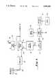
- FIG. 5is a block diagram in greater detail of the various components of the pulmonary measuring system of the present invention.
- FIG. 6is a block diagram of the transducer hook-up for the pneumotach of the present invention.
- the present systemtherefore uses a separate, sealed, electrooptical spirometer system of the type set forth in U.S. Pat. No. 4,182,175.
- the present systemis particularly usable with screening functions for detecting pulmonary problems, most particularly when used with a dynamic brake that will substantially immediately stop turbine rotation as breathing stops, thereby eliminating coast problems with the spirometer.
- Combining a dynamic brake with a sealed spirometer systemalso eliminates water problems and gas density viscosity problems.
- a pneumotach having a disposable element with a reusable handleas set forth herein, there is provided an inexpensive but effective way to eliminate water build-up in laminar flow elements.
- the contaminated itemnamely the flow tube
- the handlecomprises a seal for communication with the flow tube, and is non-disposable, but reusable.
- a flow tubegenerally designated by the numeral 10 comprising essentially a cylindrical, generally non-porous portion 11 having a generally porous portion 12 connected thereto over the left-most end of the non-porous portion 11 as shown in FIG. 1, at 13.
- the non-porous portion 11may be constructed of paper board or the like, with a thermoplastic film, or the like, thereon, or may be of substantially rigid plastic construction, if desired.
- the porous portion 12will preferably be constructed of a non-woven heat sealable filter paper, comprising many wraps or windings, until it forms a cylindrical configuration having substantial body thereto.
- the portion 11may be discussed herein as being the cardboard portion, and the portion 12 as being the porous or filter portion.
- a locating ring 14is disposed about the circumference of the cylinder 11, and is secured thereto by heat sealing, adhesive or the like, some distance from the mouthpiece end 15 of the tube.
- a porous screen 16is disposed at the rearmost end of the tube as illustrated in FIG. 1, which is the end of the tube most proximal to the patients mouth, to smooth out flow "jetting", and to screen out foreign matter.
- the left-most end of the filter portion 12is heatsealed at 17, thereby flattening out that end of the otherwise cylindrical tubular configuration for the filter portion 12, into a pillow-end-like configuration, and which serves to prevent back leakage.
- the locating ring 14is disposed with its end 18 at a precise location from the inlet end 15 of the tube, which location is also precisely coordinated with a pressure tap opening through the wall of the tube portion 11 transversely disposed as illustrated, which opening 20 is a precise distance A from the end 15 as shown, to locate the pressure tap opening at a sufficient distance away from the point of flow entry so as to eliminate "jetting" effects and to encourage the squared factor flow to remain insignificant in taking off the pressure measurement.
- the left of the tube 10, designated by the dimension "X" in FIG. 1,is likewise coordinated with the spacing A, so as to maximize the linear area of the flow through the tube 10.
- the pressure tap opening 20is made to be absolutely free of intrusion of portions of the cylindrical wall 11 into the interior of the tube 11, to eliminate adverse effects on the linearity of the measurement obtained by the transducer reacting to pressure presented to the transducer through the opening 20. It is believed that, by so constructing the opening 20, the result is a subtractive term, in the equation for the pressure, the subtractive term being a function of the square of the velocity of the flow. This subtractive term counteracts an additive term that is also a function of the square of the velocity of flow.
- the additive term that is a function of the square of the velocity of flow, and which needs counteracting,is, in turn, related to the diameter of the tube, the porosity of the element, the ratio of mouthpiece inner diameter to porous element inner diameter, and the area of the porous element.
- Ksare constants.
- the K 4 V 2 termis the subtractive term described above, which counteracts the effect of the K 3 V 2 term.
- a holder 21therefore may engage the tube 10, by being applied over its side, or in transverse approach, as is viewed in FIGS. 1 and 2, and need not be slid over the mouthpiece end 15, or opposite end 17 of the disposable tube 10.
- the holder 21will be seen to engage, in FIG. 2, the tube 10, through an arc of about 200°, leaving a non-engaged arc of about 160°.
- the holder 21thus has a concave interior 22 that terminates at the outer end at 23.
- the tube 10will be oriented against the concave face 22, such that a scribe line 24 is lined up with the end 23, to assure that the opening 20 is properly aligned with handle 26 of the holder 21.
- the handle 26has a hollow interior at 27, and an upper neck portion 28.
- a gasket or seating ring 30, of rubber or similar materialSeated at the upper end of the neck portion 28, is a gasket or seating ring 30, of rubber or similar material, having a communicating hole 31 therethrough.
- the seating ring 30is carried on a slidable sleeve 32 that is movable upwardly and downwardly toward the tube 10 and away therefrom, against the compressive force provided by compressive spring means 33, disposed in blind openings 34 in the upper end 28 of the handle 26.
- the sleeve 32is provided with a tang or manually graspable portion 35 that may be engaged by the finger of a user and pulled downwardly as viewed in FIG.
- the tang 35may be allowed to move upwardly, such that the sealing rubber or like ring 30 surrounds the hole 20 and clampingly engages the holder 26 against the tube 10.
- a tube 38 of flexible plastic, or rubber, or other materialis provided, illustrated in broken form, for reasons of space saving, to communicate with a pneumotach transducer box, in which a pressure transducer 41 is located, to be exposed to the pressure delivered from inside the tube 10 through the hole 20, and against the transducer, whereby the pressure transducer 41 may react to the flow by creating a pressure- responsive electrical signal.
- the left-most end of the tube 10'is constructed such that the left-most end 17' is provided with a plug 12', that is disc-like, if viewed in transverse section, having connected thereto a sleeve-like portion 13', such that the portion 12' and 13' comprise a separate element movably positionable at different locations inside the tube 10', in the direction of the double headed arrow 14', for instances in which specific calibration of the length Y of the tube 10' is desired.
- the gasket or seal 30, in order to conform precisely to the exterior configuration of the tube 10 at the location of the hole 20,will generally be of concave construction when viewed from above in FIG. 2.
- the upper surface of the sealing gasket 30may have various labyrinthine designs on its surface, to assure against leakage. It will be noted that by the use of a holder having an upper portion as described above, the holder may be slipped onto and off of the tube, without contamination of either end of the tube from breath of the user. In the alternative, not illustrated, the upper end of the holder could be divided into two halves, clampable over the disposable tube.
- the holder 26may readily be provided as a re-usable member, with the tube 10 constructed as a relatively inexpensive, disposable, and non-reusable member.
- the pneumotach 40is connected through a pneumotach interface 43, by means of a suitable connection means such as the male-female type connector 50, 51 illustrated, to connect to the pulmonary computer.
- the pulmonary computer 52(which comprises a microprocessor and associated components) likewise has a female connection portion 53 for receiving a male connection 54 from the spirometer 55.
- the spirometer 55can be constructed in accordance with the structure and to accomplish the functions set forth in U.S. Pat. No. 4,182,175, or in U.S. patent application Ser. No. filed on even date herewith and entitled "Dynamic Braked Spirometer," by John R. Boehringer and C. Harrison Williams, Attorney File No. 122-82, the complete disclosure of which is herein incorporated by reference, to be part of this application.
- the calculator 56(which has its own separate power supply) is designed to work with a printer or other read-out instrument 57, to print out the desired pulmonary measurements obtained by means of the pneumotach and/or spirometer.
- the pulmonary computer 52will be rechargeable, battery operated, and will include a microprocessor with all of the necessary software.
- the primary supply in calculator 56will contain battery or 110 volt converters, and suitable card reading and timing modules and will preferably contain a visible light display of information.
- the printer 57will preferably be a high speed printer having suitable graphics capability for trend recording readout printed on paper and will contain both battery and 110 volt conversion apparatus.
- the case 60includes a lid portion 61 a base portion 62, a handle 63 with hinges 64 and 65 for the connection of the lid portion 61 to the base portion 62, and with suitable clasp portions 66 and 67.
- Suitable recesses 68, 70, 71 and 72are provided in a styrofoam or like bed or block 73, for conveniently housing the various components, 10, 52, 26, 40, 43, 57, 52 and 56 of the kit, in accordance with the present invention.
- the pulmonary computer 52processes the data from the pneumotach or spirometer, and provides calibration corrections to the flow data, which are then stored in memory and/or processed for computation into formats for printing out.
- FIG. 5is a schematic block diagram of the various components of the measuring system, showing in more detail the computer and calculator and their associated components.
- the heart of the systemis central processing unit (CPU) 100, which can be a microprocessor which allows the system to be operated on batteries, and to be portable.
- Calculator 101is used to control the microprocessor.
- the calculatoris a Hewlett-Packard HP-41CV.
- the CPU 100is essentially a slave to the calculator 101. When a particular key on the calculator is pressed, a signal is sent to the computer, causing the execution of a particular function.
- commandsoriginate from calculator 101, and semi-processed transducer data are transferred from the computer back to the calculator for further processing, and output via printer 102.
- Converter 103is used to deliver all commands from the calculator to the microprocessor. For example, when a key on the calculator representing the "power up” instruction is depressed, a converter "wake-up” line is activated, which generates a pulse in power switching circuit 104. Power from the battery pack 105 is then regulated to supply the system with operating voltage. Circuit 106 provides indicator means (preferably LEDs) to inform the user that the power is on, and also to warn the user whenever the battery voltage is too low. Battery charger 107 is provided to recharge the batteries as needed.
- the converter 103When operation of the system is initiated, the converter 103 automatically resets the central processing unit 100, and the CPU then awaits further instructions. Further instructions from the calculator 101 come in the form of single ASCII coded letters, which are passed through to the CPU 100 via I/O port 109. Each instruction causes the CPU to jump to the appropriate program location, and a data acquisition routine is performed.
- Dataenters the system from at least two separate sources, as shown. First, digital data, such as from a turbine spirometer, can enter the system through I/O port 109. In the case of a spirometer which is used in conjunction with a capnometer, a delay circuit 110 may be used to cancel the effect of capnometer delay. The delay circuit 110 can be a shift register, of known design. Second, data can enter the system in analog form from a pneumotach, or from a capnometer. In the latter cases, an analog signal enters the analog-to- digital (A/D) converter 111, where the signal is converted to digital form.
- Data upon which the computer will operateis selected by the address decoder 112, which selects data from either ROM 113, RAM 114, or the analog-to-digital converter 111.
- the ROM 113contains 6K of memory, partitioned as 4K of program memory and 2K of a look-up table for linearization of pneumotach data.
- the RAMcontains 2K, which is used for temporary storage of data for output or internal program use.
- Timing of pulses, waveform generation, and event countingare accomplished by timers, of known design, in the I/O port 109.
- FIG. 6is a block diagram, showing the pneumotach transducer circuit. This circuit converts a pneumotach pressure signal, which is linearly proportional to flow, to an analog voltage. The analog voltage may be used to drive oscilloscopes or automatic data plotters.
- pneumotach 201which provides a back pressure linearly proportional to the flow, which is sent by a small-diameter plastic tube 202 to the transducer 203.
- the transducer 203is excited by the transducer board 204, and produces an analog voltage whose span and zero point may be adjusted by trim potentiometers on the board 204.
- the aim in calibrationis to obtain a zero signal at a zero flow.
- the zero circuitSince all analog circuits are subject to drift with time, temperature and physical shock, the zero circuit provides a zero voltage band on the order of plus or minus 5 millivolts during which span an LED is lit. If the absolute value of the voltage exceeds 5 millivolts, the LED goes out, notifying the user that the zero setting needs to be readjusted.
- the zero circuitis represented by reference numeral 205, and the LED is shown as 206.
- the circuit in FIG. 6is also provided with rechargeable batteries 207, and battery charger 208.
- Power switching unit 209is controlled by an on/off signal from a pulmonary computer.
- the power switching unitalso controls the circuit 210 which is an indicator that the battery voltage is too low.
- the signal from the power switching means 209is fed to a voltage regulator 211 and converter 212, which increases the voltage from 5 to 12 volts.
Landscapes
- Health & Medical Sciences (AREA)
- Life Sciences & Earth Sciences (AREA)
- Engineering & Computer Science (AREA)
- Physics & Mathematics (AREA)
- Biomedical Technology (AREA)
- Heart & Thoracic Surgery (AREA)
- Pulmonology (AREA)
- General Physics & Mathematics (AREA)
- Biophysics (AREA)
- Pathology (AREA)
- Aviation & Aerospace Engineering (AREA)
- Physiology (AREA)
- Medical Informatics (AREA)
- Molecular Biology (AREA)
- Surgery (AREA)
- Animal Behavior & Ethology (AREA)
- General Health & Medical Sciences (AREA)
- Public Health (AREA)
- Veterinary Medicine (AREA)
- Measurement Of The Respiration, Hearing Ability, Form, And Blood Characteristics Of Living Organisms (AREA)
Abstract
Description
P=K.sub.1 +K.sub.2 V+K.sub.3 V.sup.2 -K.sub.4 V.sup.2
Claims (4)
Priority Applications (1)
| Application Number | Priority Date | Filing Date | Title |
|---|---|---|---|
| US07/303,493US4995400A (en) | 1982-08-27 | 1989-01-27 | Pneumotach and components therefor |
Applications Claiming Priority (2)
| Application Number | Priority Date | Filing Date | Title |
|---|---|---|---|
| US06/412,227US4807641A (en) | 1982-08-27 | 1982-08-27 | Pneumotach and components therefore and combined pulmonary function measuring kit containing the same |
| US07/303,493US4995400A (en) | 1982-08-27 | 1989-01-27 | Pneumotach and components therefor |
Related Parent Applications (1)
| Application Number | Title | Priority Date | Filing Date |
|---|---|---|---|
| US06/412,227ContinuationUS4807641A (en) | 1982-08-27 | 1982-08-27 | Pneumotach and components therefore and combined pulmonary function measuring kit containing the same |
Publications (1)
| Publication Number | Publication Date |
|---|---|
| US4995400Atrue US4995400A (en) | 1991-02-26 |
Family
ID=26973483
Family Applications (1)
| Application Number | Title | Priority Date | Filing Date |
|---|---|---|---|
| US07/303,493Expired - LifetimeUS4995400A (en) | 1982-08-27 | 1989-01-27 | Pneumotach and components therefor |
Country Status (1)
| Country | Link |
|---|---|
| US (1) | US4995400A (en) |
Cited By (25)
| Publication number | Priority date | Publication date | Assignee | Title |
|---|---|---|---|---|
| US5193531A (en)* | 1991-02-14 | 1993-03-16 | L'air Liquide, Societe Anonyme Pour L'etude Et L'exploitation Des Procedes Georges Claude | Process and apparatus for controlling a gas pressure and system for supplying gas comprising such device |
| US5279304A (en)* | 1992-04-30 | 1994-01-18 | Robert K. Einhorn | Nasal volume meter |
| US5357972A (en)* | 1993-05-17 | 1994-10-25 | Medical Graphics Corporation | Disposable pneumotachograph flowmeter |
| WO1995026889A1 (en)* | 1994-03-30 | 1995-10-12 | Drager Australia Pty. Ltd. | Control device and mouthpiece |
| US5564432A (en)* | 1994-07-13 | 1996-10-15 | Thomson; Ronald A. | Biodegradable air tube and spirometer employing same |
| US5715831A (en)* | 1996-06-21 | 1998-02-10 | Desert Moon Development Limited Partnership | Calibrated air tube for spirometer |
| US5743270A (en)* | 1996-06-21 | 1998-04-28 | Desert Moon Development Limited Partnership | Resistive element for spirometer |
| US5816246A (en)* | 1994-09-15 | 1998-10-06 | Mirza; M. Zubair | Electronic pocket spirometer |
| US5925831A (en)* | 1997-10-18 | 1999-07-20 | Cardiopulmonary Technologies, Inc. | Respiratory air flow sensor |
| US5997483A (en)* | 1996-06-21 | 1999-12-07 | Desert Moon Development Limited Partnership | Individualized and calibrated air tube for spirometer |
| US20040254491A1 (en)* | 2003-06-13 | 2004-12-16 | Cardiopulmonary Technologies, Inc. | Gas flow diverter for respiratory monitoring device |
| US20050245837A1 (en)* | 2004-04-28 | 2005-11-03 | Medpond, Llc | Mouthpiece for use in a spirometer |
| US20060025727A1 (en)* | 2003-09-16 | 2006-02-02 | Boehringer Laboratories, Inc. | Apparatus and method for suction-assisted wound healing |
| US20060155206A1 (en)* | 1997-01-27 | 2006-07-13 | Lynn Lawrence A | System and method for sound and oximetry integration |
| US20060189880A1 (en)* | 1997-01-27 | 2006-08-24 | Lynn Lawrence A | Airway instability detection system and method |
| US20060195041A1 (en)* | 2002-05-17 | 2006-08-31 | Lynn Lawrence A | Centralized hospital monitoring system for automatically detecting upper airway instability and for preventing and aborting adverse drug reactions |
| US20070093721A1 (en)* | 2001-05-17 | 2007-04-26 | Lynn Lawrence A | Microprocessor system for the analysis of physiologic and financial datasets |
| US20070149860A1 (en)* | 1992-08-19 | 2007-06-28 | Lynn Lawrence A | Microprocessor system for the analysis of physiologic and financial datasets |
| US20080287756A1 (en)* | 1997-07-14 | 2008-11-20 | Lynn Lawrence A | Pulse oximetry relational alarm system for early recognition of instability and catastrophic occurrences |
| US20090281838A1 (en)* | 2008-05-07 | 2009-11-12 | Lawrence A. Lynn | Medical failure pattern search engine |
| US20090281839A1 (en)* | 2002-05-17 | 2009-11-12 | Lawrence A. Lynn | Patient safety processor |
| US20100174161A1 (en)* | 2006-02-10 | 2010-07-08 | Lynn Lawrence A | System and method for the detection of physiologic response to stimulation |
| US8666467B2 (en) | 2001-05-17 | 2014-03-04 | Lawrence A. Lynn | System and method for SPO2 instability detection and quantification |
| US9042952B2 (en) | 1997-01-27 | 2015-05-26 | Lawrence A. Lynn | System and method for automatic detection of a plurality of SPO2 time series pattern types |
| US9521971B2 (en) | 1997-07-14 | 2016-12-20 | Lawrence A. Lynn | System and method for automatic detection of a plurality of SPO2 time series pattern types |
Citations (5)
| Publication number | Priority date | Publication date | Assignee | Title |
|---|---|---|---|---|
| US2315756A (en)* | 1941-08-12 | 1943-04-06 | Warner Louis Allen | Air speed and similar indicator |
| US3608546A (en)* | 1970-01-21 | 1971-09-28 | Gen Electric | Fluidic spirometer |
| US3924612A (en)* | 1974-01-28 | 1975-12-09 | Philip T Dempster | Spirometer apparatus and method |
| US4051843A (en)* | 1975-02-26 | 1977-10-04 | Siemens Aktiengesellschaft | Apparatus for the determination of the respiratory passageway resistance |
| US4807641A (en)* | 1982-08-27 | 1989-02-28 | Boehringer Laboratories | Pneumotach and components therefore and combined pulmonary function measuring kit containing the same |
- 1989
- 1989-01-27USUS07/303,493patent/US4995400A/ennot_activeExpired - Lifetime
Patent Citations (5)
| Publication number | Priority date | Publication date | Assignee | Title |
|---|---|---|---|---|
| US2315756A (en)* | 1941-08-12 | 1943-04-06 | Warner Louis Allen | Air speed and similar indicator |
| US3608546A (en)* | 1970-01-21 | 1971-09-28 | Gen Electric | Fluidic spirometer |
| US3924612A (en)* | 1974-01-28 | 1975-12-09 | Philip T Dempster | Spirometer apparatus and method |
| US4051843A (en)* | 1975-02-26 | 1977-10-04 | Siemens Aktiengesellschaft | Apparatus for the determination of the respiratory passageway resistance |
| US4807641A (en)* | 1982-08-27 | 1989-02-28 | Boehringer Laboratories | Pneumotach and components therefore and combined pulmonary function measuring kit containing the same |
Cited By (54)
| Publication number | Priority date | Publication date | Assignee | Title |
|---|---|---|---|---|
| US5193531A (en)* | 1991-02-14 | 1993-03-16 | L'air Liquide, Societe Anonyme Pour L'etude Et L'exploitation Des Procedes Georges Claude | Process and apparatus for controlling a gas pressure and system for supplying gas comprising such device |
| US5279304A (en)* | 1992-04-30 | 1994-01-18 | Robert K. Einhorn | Nasal volume meter |
| US20070149860A1 (en)* | 1992-08-19 | 2007-06-28 | Lynn Lawrence A | Microprocessor system for the analysis of physiologic and financial datasets |
| US8152732B2 (en) | 1992-08-19 | 2012-04-10 | Lynn Lawrence A | Microprocessor system for the analysis of physiologic and financial datasets |
| US5357972A (en)* | 1993-05-17 | 1994-10-25 | Medical Graphics Corporation | Disposable pneumotachograph flowmeter |
| WO1995026889A1 (en)* | 1994-03-30 | 1995-10-12 | Drager Australia Pty. Ltd. | Control device and mouthpiece |
| US5564432A (en)* | 1994-07-13 | 1996-10-15 | Thomson; Ronald A. | Biodegradable air tube and spirometer employing same |
| US5735287A (en)* | 1994-07-13 | 1998-04-07 | Desert Moon Development Limited Partnership | Biodegradable air tube and spirometer employing same |
| EP0776177A4 (en)* | 1994-07-13 | 1998-10-14 | Ronald A Thomson | Biodegradable air tube and spirometer employing same |
| US6176833B1 (en) | 1994-07-13 | 2001-01-23 | Desert Moon Development | Biodegradable air tube and spirometer employing same |
| US5980466A (en)* | 1994-07-13 | 1999-11-09 | Desert Moon Development - Limited Partnership | Biodegradable air tube and spirometer employing same |
| US5816246A (en)* | 1994-09-15 | 1998-10-06 | Mirza; M. Zubair | Electronic pocket spirometer |
| US5997483A (en)* | 1996-06-21 | 1999-12-07 | Desert Moon Development Limited Partnership | Individualized and calibrated air tube for spirometer |
| US6113549A (en)* | 1996-06-21 | 2000-09-05 | Desert Moon Development | Individualized and calibrated air tube for spirometer |
| US5743270A (en)* | 1996-06-21 | 1998-04-28 | Desert Moon Development Limited Partnership | Resistive element for spirometer |
| US5715831A (en)* | 1996-06-21 | 1998-02-10 | Desert Moon Development Limited Partnership | Calibrated air tube for spirometer |
| US9468378B2 (en) | 1997-01-27 | 2016-10-18 | Lawrence A. Lynn | Airway instability detection system and method |
| US9042952B2 (en) | 1997-01-27 | 2015-05-26 | Lawrence A. Lynn | System and method for automatic detection of a plurality of SPO2 time series pattern types |
| US8187201B2 (en) | 1997-01-27 | 2012-05-29 | Lynn Lawrence A | System and method for applying continuous positive airway pressure |
| US20060155206A1 (en)* | 1997-01-27 | 2006-07-13 | Lynn Lawrence A | System and method for sound and oximetry integration |
| US20060189880A1 (en)* | 1997-01-27 | 2006-08-24 | Lynn Lawrence A | Airway instability detection system and method |
| US20100234705A1 (en)* | 1997-01-27 | 2010-09-16 | Lynn Lawrence A | System and Method for Automatic Detection of a Plurality of SP02 Time Series Pattern Types |
| US20060235324A1 (en)* | 1997-01-27 | 2006-10-19 | Lynn Lawrence A | System and method for applying continuous positive airway pressure |
| US20100079292A1 (en)* | 1997-01-27 | 2010-04-01 | Lawrence A. Lynn | Microprocessor system for the analysis of physiologic and financial datasets |
| US20080287756A1 (en)* | 1997-07-14 | 2008-11-20 | Lynn Lawrence A | Pulse oximetry relational alarm system for early recognition of instability and catastrophic occurrences |
| US9521971B2 (en) | 1997-07-14 | 2016-12-20 | Lawrence A. Lynn | System and method for automatic detection of a plurality of SPO2 time series pattern types |
| US5925831A (en)* | 1997-10-18 | 1999-07-20 | Cardiopulmonary Technologies, Inc. | Respiratory air flow sensor |
| US20070129647A1 (en)* | 2000-07-28 | 2007-06-07 | Lynn Lawrence A | System and method for CO2 and oximetry integration |
| US10058269B2 (en) | 2000-07-28 | 2018-08-28 | Lawrence A. Lynn | Monitoring system for identifying an end-exhalation carbon dioxide value of enhanced clinical utility |
| US8932227B2 (en)* | 2000-07-28 | 2015-01-13 | Lawrence A. Lynn | System and method for CO2 and oximetry integration |
| US8666467B2 (en) | 2001-05-17 | 2014-03-04 | Lawrence A. Lynn | System and method for SPO2 instability detection and quantification |
| US8862196B2 (en) | 2001-05-17 | 2014-10-14 | Lawrence A. Lynn | System and method for automatic detection of a plurality of SP02 time series pattern types |
| US11439321B2 (en) | 2001-05-17 | 2022-09-13 | Lawrence A. Lynn | Monitoring system for identifying an end-exhalation carbon dioxide value of enhanced clinical utility |
| US10366790B2 (en) | 2001-05-17 | 2019-07-30 | Lawrence A. Lynn | Patient safety processor |
| US10354753B2 (en) | 2001-05-17 | 2019-07-16 | Lawrence A. Lynn | Medical failure pattern search engine |
| US20110208539A1 (en)* | 2001-05-17 | 2011-08-25 | Lynn Lawrence A | System and method for automatic detection of a plurality of sp02 time series pattern types |
| US10297348B2 (en) | 2001-05-17 | 2019-05-21 | Lawrence A. Lynn | Patient safety processor |
| US20070093721A1 (en)* | 2001-05-17 | 2007-04-26 | Lynn Lawrence A | Microprocessor system for the analysis of physiologic and financial datasets |
| US10032526B2 (en) | 2001-05-17 | 2018-07-24 | Lawrence A. Lynn | Patient safety processor |
| US9031793B2 (en) | 2001-05-17 | 2015-05-12 | Lawrence A. Lynn | Centralized hospital monitoring system for automatically detecting upper airway instability and for preventing and aborting adverse drug reactions |
| US20090281839A1 (en)* | 2002-05-17 | 2009-11-12 | Lawrence A. Lynn | Patient safety processor |
| US20060195041A1 (en)* | 2002-05-17 | 2006-08-31 | Lynn Lawrence A | Centralized hospital monitoring system for automatically detecting upper airway instability and for preventing and aborting adverse drug reactions |
| US9053222B2 (en) | 2002-05-17 | 2015-06-09 | Lawrence A. Lynn | Patient safety processor |
| US7981098B2 (en) | 2002-09-16 | 2011-07-19 | Boehringer Technologies, L.P. | System for suction-assisted wound healing |
| US8460203B2 (en) | 2003-06-13 | 2013-06-11 | Treymed, Inc. | Gas flow diverter for respiratory monitoring device |
| US7878980B2 (en) | 2003-06-13 | 2011-02-01 | Treymed, Inc. | Gas flow diverter for respiratory monitoring device |
| US20040254491A1 (en)* | 2003-06-13 | 2004-12-16 | Cardiopulmonary Technologies, Inc. | Gas flow diverter for respiratory monitoring device |
| US20060025727A1 (en)* | 2003-09-16 | 2006-02-02 | Boehringer Laboratories, Inc. | Apparatus and method for suction-assisted wound healing |
| US7625362B2 (en)* | 2003-09-16 | 2009-12-01 | Boehringer Technologies, L.P. | Apparatus and method for suction-assisted wound healing |
| US20050245837A1 (en)* | 2004-04-28 | 2005-11-03 | Medpond, Llc | Mouthpiece for use in a spirometer |
| WO2005104788A3 (en)* | 2004-04-28 | 2007-02-08 | Meddorna Llc | Mouthpiece for use in a spirometer |
| US8728001B2 (en) | 2006-02-10 | 2014-05-20 | Lawrence A. Lynn | Nasal capnographic pressure monitoring system |
| US20100174161A1 (en)* | 2006-02-10 | 2010-07-08 | Lynn Lawrence A | System and method for the detection of physiologic response to stimulation |
| US20090281838A1 (en)* | 2008-05-07 | 2009-11-12 | Lawrence A. Lynn | Medical failure pattern search engine |
Similar Documents
| Publication | Publication Date | Title |
|---|---|---|
| US4995400A (en) | Pneumotach and components therefor | |
| US4807641A (en) | Pneumotach and components therefore and combined pulmonary function measuring kit containing the same | |
| US3884219A (en) | System for determining temperature and respiration rate | |
| US4307730A (en) | Apparatus for pulmonary function analysis | |
| US3608546A (en) | Fluidic spirometer | |
| US4096855A (en) | Incentive spirometer | |
| US5107860A (en) | Method and apparatus of analyzing the functioning of the lungs | |
| US3903742A (en) | Disposable respiratory parameter sensor | |
| US6709403B1 (en) | Manometer CO2 detector combination | |
| JPS6368179A (en) | Carbon dioxide detector | |
| EP0027154B1 (en) | Volumetric respiratory exerciser and kit for assembling such an exerciser | |
| AU5352396A (en) | A device for detecting components in exhaled air | |
| US2792828A (en) | Apparatus for determining metabolic rates | |
| US5620005A (en) | Calibration apparatus for the pressure gauges of a whole-body plethysmograph | |
| US5211180A (en) | Respiratory test apparatus | |
| US4520668A (en) | Manometric instrument for underwater diving | |
| US5316647A (en) | Portable oxygen analyzer | |
| GB2238389A (en) | Respirometer | |
| US5542414A (en) | Gas supplying head enclosure with expandable pressure indicator | |
| SU599796A1 (en) | Impedance-type pneumograph | |
| DE59406103D1 (en) | Reference impedance for the calibration of the pressure and flow measuring device of a device for the oscillometric measurement of airway resistance | |
| Brody et al. | Simple, Convenient Apparatus for Measuring Maximal Midtidal Pressures and Flows | |
| SU650611A1 (en) | Device for examening breath mechanics | |
| Gottlieb et al. | Body plethysmograph for respiratory measurements of unanesthetized small animals | |
| CN201154139Y (en) | Trachea duct capable of measuring temperature |
Legal Events
| Date | Code | Title | Description |
|---|---|---|---|
| STCF | Information on status: patent grant | Free format text:PATENTED CASE | |
| FPAY | Fee payment | Year of fee payment:4 | |
| FEPP | Fee payment procedure | Free format text:PAT HLDR NO LONGER CLAIMS SMALL ENT STAT AS SMALL BUSINESS (ORIGINAL EVENT CODE: LSM2); ENTITY STATUS OF PATENT OWNER: LARGE ENTITY | |
| FPAY | Fee payment | Year of fee payment:8 | |
| AS | Assignment | Owner name:BANKERS TRUST COMPANY, AS ADMINISTRATIVE AGENT, NE Free format text:GRANT OF PATENT SECURITY INTEREST;ASSIGNOR:HUDSON RESPIRATORY CARE, INC.;REEL/FRAME:012831/0422 Effective date:20020412 | |
| FPAY | Fee payment | Year of fee payment:12 | |
| AS | Assignment | Owner name:HUDSON RESPIRATORY CARE INC., CALIFORNIA Free format text:RELEASE OF SECURITY INTEREST;ASSIGNOR:DEUTSCHE BANK TRUST COMPANY;REEL/FRAME:014588/0312 Effective date:20031007 Owner name:WELLS FARGO FOOTHILL, INC., CALIFORNIA Free format text:SECURITY AGREEMENT;ASSIGNOR:HUDSON RESPIRATORY CARE INC;REEL/FRAME:014588/0831 Effective date:20031007 | |
| AS | Assignment | Owner name:MW POST ADVISORY GROUP, LLC, AS AGENT, CALIFORNIA Free format text:SECURITY INTEREST;ASSIGNOR:HUDSON RESPIRATORY CARE INC.;REEL/FRAME:014646/0001 Effective date:20031007 | |
| AS | Assignment | Owner name:HUDSON RESPIRATORY CARE, INC., CALIFORNIA Free format text:RELEASE OF PATENT SECURITY INTERESTS;ASSIGNOR:DEUTSCHE BANK TRUST COMPANY AMERICAS (FORMERLY KNOWN AS BANKERS TRUST COMPANY);REEL/FRAME:014763/0991 Effective date:20040618 | |
| AS | Assignment | Owner name:WELLS FARGO FOOTHILL, INC., CALIFORNIA Free format text:RELEASE OF PATENT SECURITY INTERESTS;ASSIGNOR:HUDSON RESPIRATORY CARE INC;REEL/FRAME:014822/0356 Effective date:20040706 | |
| AS | Assignment | Owner name:HUDSON RESPIRATORY CARE, INC. A CALIFORNIA CORPORA Free format text:RELEASE OF SECURITY INTEREST - PATENTS;ASSIGNOR:WELLS FARGO FOOTHILL, INC.;REEL/FRAME:014852/0541 Effective date:20040706 |