US4993959A - Grounding clip - Google Patents
Grounding clipDownload PDFInfo
- Publication number
- US4993959A US4993959AUS07/467,817US46781790AUS4993959AUS 4993959 AUS4993959 AUS 4993959AUS 46781790 AUS46781790 AUS 46781790AUS 4993959 AUS4993959 AUS 4993959A
- Authority
- US
- United States
- Prior art keywords
- grounding clip
- panel
- wire
- strain relief
- section
- Prior art date
- Legal status (The legal status is an assumption and is not a legal conclusion. Google has not performed a legal analysis and makes no representation as to the accuracy of the status listed.)
- Expired - Lifetime
Links
- 230000014759maintenance of locationEffects0.000claimsdescription2
- 238000000605extractionMethods0.000description7
- 229910001335Galvanized steelInorganic materials0.000description2
- 229910000831SteelInorganic materials0.000description2
- 229910052782aluminiumInorganic materials0.000description2
- XAGFODPZIPBFFR-UHFFFAOYSA-NaluminiumChemical compound[Al]XAGFODPZIPBFFR-UHFFFAOYSA-N0.000description2
- 239000008397galvanized steelSubstances0.000description2
- 230000037431insertionEffects0.000description2
- 238000003780insertionMethods0.000description2
- 238000009413insulationMethods0.000description2
- 239000000463materialSubstances0.000description2
- 229910052751metalInorganic materials0.000description2
- 239000002184metalSubstances0.000description2
- 239000010959steelSubstances0.000description2
- 229910000906BronzeInorganic materials0.000description1
- OAICVXFJPJFONN-UHFFFAOYSA-NPhosphorusChemical compound[P]OAICVXFJPJFONN-UHFFFAOYSA-N0.000description1
- ATJFFYVFTNAWJD-UHFFFAOYSA-NTinChemical compound[Sn]ATJFFYVFTNAWJD-UHFFFAOYSA-N0.000description1
- 238000005452bendingMethods0.000description1
- 239000010974bronzeSubstances0.000description1
- 238000010276constructionMethods0.000description1
- KUNSUQLRTQLHQQ-UHFFFAOYSA-Ncopper tinChemical compound[Cu].[Sn]KUNSUQLRTQLHQQ-UHFFFAOYSA-N0.000description1
- 238000002788crimpingMethods0.000description1
Images


Classifications
- H—ELECTRICITY
- H01—ELECTRIC ELEMENTS
- H01R—ELECTRICALLY-CONDUCTIVE CONNECTIONS; STRUCTURAL ASSOCIATIONS OF A PLURALITY OF MUTUALLY-INSULATED ELECTRICAL CONNECTING ELEMENTS; COUPLING DEVICES; CURRENT COLLECTORS
- H01R4/00—Electrically-conductive connections between two or more conductive members in direct contact, i.e. touching one another; Means for effecting or maintaining such contact; Electrically-conductive connections having two or more spaced connecting locations for conductors and using contact members penetrating insulation
- H01R4/58—Electrically-conductive connections between two or more conductive members in direct contact, i.e. touching one another; Means for effecting or maintaining such contact; Electrically-conductive connections having two or more spaced connecting locations for conductors and using contact members penetrating insulation characterised by the form or material of the contacting members
- H01R4/66—Connections with the terrestrial mass, e.g. earth plate, earth pin
- H—ELECTRICITY
- H01—ELECTRIC ELEMENTS
- H01R—ELECTRICALLY-CONDUCTIVE CONNECTIONS; STRUCTURAL ASSOCIATIONS OF A PLURALITY OF MUTUALLY-INSULATED ELECTRICAL CONNECTING ELEMENTS; COUPLING DEVICES; CURRENT COLLECTORS
- H01R4/00—Electrically-conductive connections between two or more conductive members in direct contact, i.e. touching one another; Means for effecting or maintaining such contact; Electrically-conductive connections having two or more spaced connecting locations for conductors and using contact members penetrating insulation
- H01R4/58—Electrically-conductive connections between two or more conductive members in direct contact, i.e. touching one another; Means for effecting or maintaining such contact; Electrically-conductive connections having two or more spaced connecting locations for conductors and using contact members penetrating insulation characterised by the form or material of the contacting members
- H01R4/64—Connections between or with conductive parts having primarily a non-electric function, e.g. frame, casing, rail
Definitions
- This applicationrelates to a grounding clip for use in establishing an interconnection between a wire and a metallic panel such as a panel used in an electrical appliance.
- a common way in which components of an electrical assembly are groundedis to attach a ground wire to a metallic portion of the chassis. Often this interconnection is made to a metal panel such as a 0.022 inch thick aluminum panel, a 0.024 inch painted steel panel or a 0.033 inch galvanized steel panel.
- a metal panelsuch as a 0.022 inch thick aluminum panel, a 0.024 inch painted steel panel or a 0.033 inch galvanized steel panel.
- These grounding connectionsare conventionally made using a prior art grounding clip which comprises a U shaped terminal having a crimp barrel extending from one side edge of the bight or central section of the U shaped clip.
- the prior art clip, shown in FIG. 8has two sidewalls extending upwardly from a central bight. Tabs or inwardly struck from the center of the ground plate and these tabs dig into the opposite sides of the panel.
- the U shaped grounding clipis simply inserted on one edge of the plate. Since the tabs extending from the central portion of the plate are inclined, these tabs can be deflected during insertion of the clip onto the panel. However, the free edges of the tabs engage the panel to resist retraction.
- FIG. 9shows a prior art grounding clip intended for use between two panels.
- the grounding clip shown in FIG. 9includes serrations or tines struck along the edges of the panel contact section as opposed to the tabs struck from the center of the walls of the panel contact sections of the clip shown in FIG. 8. These sheared tines or teeth can establish a good electrical and mechanical connection.
- the grounding clip shown in FIG. 9, however,is intended only for interconnecting two panels. Note that the arm extending from the center of the U shaped panel contact portion is configured as a beam for engaging an adjacent panel.
- the instant inventioncomprises a grounding clip for attaching a wire to a panel.
- This grounding cliphas a crimp section extending from one edge, but it also has a centrally disposed wire strain relief. Any force applied to the wire will be transmitted directly to the grounding clip through the central strain relief thus resulting in a straight pulling action.
- This straight pulling actionrequires greater extraction forces than would be required for conventional grounding clips in which the force is applied through an outboard crimp section resulting in rotation rather than straight pull action.
- This grounding clipis used to form an electrical interconnection between a ground wire and an electrically conductive panel.
- the grounding clipis stamped and formed and has a U shaped panel contact section having opposed walls which extend upwardly on opposite sides of the central bight. Tines or serrations protrude inwardly from each wall to grip the panel.
- a wire contact sectionextends from the panel contact section and includes means for establishing an electrical interconnection to a ground wire.
- a strain relief armextends from one of two walls of the panel contact section. The other wall of the panel contact section has a slot from which the strain relief is formed. Any extraction force applied to a wire will be transmitted to the panel gripping section through the centrally disposed strain relief instead of through the offset wire contact section, thus increasing the amount of extraction force needed to remove the grounding clip from the panel.
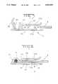
- FIG. 1is a front view of the grounding clip showing the wire crimp section and strain relief section prior to attachment to a wire.
- FIG. 2is a view similar to FIG. 1, but showing a wire attached to the grounding clip with the strain relief crimped around the insulation on the wire and the wire crimp section engaging a stripped free end. This figure also shows the clip engaging a panel.
- FIG. 3is an end view of the grounding clip prior to attachment to either a wire or a panel.
- FIG. 4is a view similar to FIG. 3, but showing the grounding clip attached to both a wire and a panel.
- FIG. 5is a view of the blank of the grounding clip prior to forming.
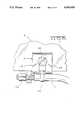
- FIG. 6is a view of the grounding clip used with an auxiliary fastener such as a screw.
- FIGS. 7A and 7Bshow an alternate embodiment of the invention depicting the use of a different wire barrel.
- FIG. 8is a view of a prior art grounding clip used to interconnect a wire to a panel.
- FIG. 9is a view of a prior art grounding clip used to interconnect two panels.
- the grounding clip 2comprising the preferred embodiment of this invention is intended for forming an electrical interconnection between a ground wire 4 and a panel 6.
- the grounding clip 2comprises a stamped and formed member fabricated of a conventional spring metal such as tin plated phosphor bronze.
- the grounding clip comprising the preferred embodiment of the inventionis intended for use with 18 gauge wire, although grounding clips of this type could be used for other wire sizes.
- the grounding clip comprising the preferred embodiment of this inventionis suitable for use with a plurality of different panels having different thicknesses and formed of different materials. In particular, the same grounding clip could be used to establish an interconnection to 0.022 inch thick aluminum panels or 0.024 inch thick painted steel panels, or 0.033 inch galvanized steel panels. It should be understood that not only could the preferred embodiment of this invention be used with other panels, but that this invention, can be fabricated in different sizes and could be employed with panels having more or less thickness and fabricated of different materials.
- Grounding clip 2comprises a U shaped panel contact section 10 and a wire contact section 20.
- the U shaped panel contact section 10has a pair of oppositely facing walls 12a and 12b extending upwardly from a central radiused bight 16.
- both electrical and mechanical interconnection to the panelis established by tines or serrations 18 formed inwardly along the edges 14 of the U shaped panel contact section 10. These tines or serrations 18 protrude inwardly from each wall 12 and form an inclined gripping engagement with the panel 6.
- Each serrationis inclined inwardly relative to the walls and extends toward the bight 16.
- the tabs 18have a greater retention force when subjected to a straight pull exerted on the U shaped panel contact section 10 than when subjected to a force tending to impart rotation to the U shaped panel contact section 10.
- the tines or serrations 14have sharp points which facilitate digging into the panels. Since the tines 18 are inclined towards the bight, the U shaped panel contact section can be inserted onto the edge of a panel 6. During insertion the tines or serrations 18 will be deflected inwardly. It can readily be seen that it would require a greater extraction force to remove the clip 2 from the panel 4 than the force required to insert the clip 2 onto the panel 4.
- the U shaped panel contact section 10also has a strain relief arm 22 which extends from one of the walls 12b of the U shaped panel contact section 10. Strain relief arm 22 extends from one of the walls 12 past the bight 16. Strain relief arm 22 extends from the center of the U shaped panel contact section 10 so that a force exerted on the wire to which the strain relief arm is attached, is transferred to the U shaped panel contact section 10 as a straight pull rather than a rotational force. The strain relief arm 22 is struck from a slot 24 extending into the other wall 12a. In order to attach the strain relief arm 22, a crimping force is applied to the arm 22 and the arm is crimped around the insulation surrounding the grounding wire 4. Typically, the grounding clip would be applied to the wire 4 before the grounding clip is attached to the panel 6.
- the wire contact section 20comprises a crimp section of conventional construction suitable for establishing an electrical connection to the stripped end of an insulated wire.
- the wire contact section 20is disposed below the bight and is located on one side of the U shaped section 10. Forces applied directly to the wire contact section 20 would tend to be transmitted to the U shaped member 10 as a rotational force rather than a straight pull force.
- the wire contact section 10comprises a deformable section configured to be crimped around the associated portion of the ground wire.
- a force applied to the wirewill be transmitted first through the strain relief arm directly to the U shaped panel contact section 10 thus resulting in a straight pull action.
- the straight pull action transmitted through the centrally disposed strain relief arm 22will increase the extraction force needed to remove the grounding clip 2 from the panel.
- FIG. 6shows an alternate use of this same grounding clip.
- a screw 30can be used to permanently attach the grounding clip to the panel 6, provided an appropriate clearance hole is located along the edge of the panel 6.
- the screwcan be inserted through the slot 24 when the grounding clip 2 is properly positioned in alignment with the clearance hole in the panel and then tapped into the pilot hole 28.
- an auxiliary pilot hole 28is provided in the wall 12b from which the strain relief 22 extends. This pilot hole 28 is in alignment with the slot 24 in the opposite wall.
- This grounding clipis normally intended for use adjacent the end of a ground wire. However, since both the wire contact section 20 and the strain relief arm 22 are offset from the U shaped panel receiving slot, this grounding clip 2 can be used with a center strip and through wire.
- Grounding clip 102 shown in FIGS. 7A and 7Bfunctions in the same manner, but this embodiment has a different wire contact section 120.
- Other configurations embodying this inventionwould be apparent to one of ordinary skill in the art.
Landscapes
- Multi-Conductor Connections (AREA)
- Connections Effected By Soldering, Adhesion, Or Permanent Deformation (AREA)
- Clamps And Clips (AREA)
- Installation Of Indoor Wiring (AREA)
Abstract
Description
1. Field of the Invention
This application relates to a grounding clip for use in establishing an interconnection between a wire and a metallic panel such as a panel used in an electrical appliance. 2. Description of the Prior Art
A common way in which components of an electrical assembly are grounded is to attach a ground wire to a metallic portion of the chassis. Often this interconnection is made to a metal panel such as a 0.022 inch thick aluminum panel, a 0.024 inch painted steel panel or a 0.033 inch galvanized steel panel. These grounding connections are conventionally made using a prior art grounding clip which comprises a U shaped terminal having a crimp barrel extending from one side edge of the bight or central section of the U shaped clip. The prior art clip, shown in FIG. 8 has two sidewalls extending upwardly from a central bight. Tabs or inwardly struck from the center of the ground plate and these tabs dig into the opposite sides of the panel. The U shaped grounding clip is simply inserted on one edge of the plate. Since the tabs extending from the central portion of the plate are inclined, these tabs can be deflected during insertion of the clip onto the panel. However, the free edges of the tabs engage the panel to resist retraction.
One problem that can be encountered with these conventional grounding clips having a crimp barrel extending from an outboard edge of the panel contact portion is that a force applied to the wire can cause rotation of the panel contact portion. This rotation makes it easier to pull the grounding clip out of engagement with the panel. In many applications minimum extraction force is a requirement and this prior art configuration tends to limit the extraction force which can be attained with such a device. Alternatively, a force applied to the wire can cause bending of the crimp barrel, thus causing permanent damage to the grounding clip.
In addition to conventional grounding clips used to attach a wire to a panel, other conventional grounding clips have been employed for interconnecting two panels. FIG. 9 shows a prior art grounding clip intended for use between two panels. The grounding clip shown in FIG. 9 includes serrations or tines struck along the edges of the panel contact section as opposed to the tabs struck from the center of the walls of the panel contact sections of the clip shown in FIG. 8. These sheared tines or teeth can establish a good electrical and mechanical connection. The grounding clip shown in FIG. 9, however, is intended only for interconnecting two panels. Note that the arm extending from the center of the U shaped panel contact portion is configured as a beam for engaging an adjacent panel.
The instant invention comprises a grounding clip for attaching a wire to a panel. This grounding clip has a crimp section extending from one edge, but it also has a centrally disposed wire strain relief. Any force applied to the wire will be transmitted directly to the grounding clip through the central strain relief thus resulting in a straight pulling action. This straight pulling action requires greater extraction forces than would be required for conventional grounding clips in which the force is applied through an outboard crimp section resulting in rotation rather than straight pull action.
This grounding clip is used to form an electrical interconnection between a ground wire and an electrically conductive panel. The grounding clip is stamped and formed and has a U shaped panel contact section having opposed walls which extend upwardly on opposite sides of the central bight. Tines or serrations protrude inwardly from each wall to grip the panel. A wire contact section extends from the panel contact section and includes means for establishing an electrical interconnection to a ground wire. A strain relief arm extends from one of two walls of the panel contact section. The other wall of the panel contact section has a slot from which the strain relief is formed. Any extraction force applied to a wire will be transmitted to the panel gripping section through the centrally disposed strain relief instead of through the offset wire contact section, thus increasing the amount of extraction force needed to remove the grounding clip from the panel.
FIG. 1 is a front view of the grounding clip showing the wire crimp section and strain relief section prior to attachment to a wire.
FIG. 2 is a view similar to FIG. 1, but showing a wire attached to the grounding clip with the strain relief crimped around the insulation on the wire and the wire crimp section engaging a stripped free end. This figure also shows the clip engaging a panel.
FIG. 3 is an end view of the grounding clip prior to attachment to either a wire or a panel.
FIG. 4 is a view similar to FIG. 3, but showing the grounding clip attached to both a wire and a panel.
FIG. 5 is a view of the blank of the grounding clip prior to forming.
FIG. 6 is a view of the grounding clip used with an auxiliary fastener such as a screw.
FIGS. 7A and 7B show an alternate embodiment of the invention depicting the use of a different wire barrel.
FIG. 8 is a view of a prior art grounding clip used to interconnect a wire to a panel.
FIG. 9 is a view of a prior art grounding clip used to interconnect two panels.
Thegrounding clip 2 comprising the preferred embodiment of this invention is intended for forming an electrical interconnection between aground wire 4 and apanel 6. Thegrounding clip 2 comprises a stamped and formed member fabricated of a conventional spring metal such as tin plated phosphor bronze. The grounding clip comprising the preferred embodiment of the invention is intended for use with 18 gauge wire, although grounding clips of this type could be used for other wire sizes. The grounding clip comprising the preferred embodiment of this invention is suitable for use with a plurality of different panels having different thicknesses and formed of different materials. In particular, the same grounding clip could be used to establish an interconnection to 0.022 inch thick aluminum panels or 0.024 inch thick painted steel panels, or 0.033 inch galvanized steel panels. It should be understood that not only could the preferred embodiment of this invention be used with other panels, but that this invention, can be fabricated in different sizes and could be employed with panels having more or less thickness and fabricated of different materials.
The U shapedpanel contact section 10 also has astrain relief arm 22 which extends from one of thewalls 12b of the U shapedpanel contact section 10.Strain relief arm 22 extends from one of thewalls 12 past thebight 16.Strain relief arm 22 extends from the center of the U shapedpanel contact section 10 so that a force exerted on the wire to which the strain relief arm is attached, is transferred to the U shapedpanel contact section 10 as a straight pull rather than a rotational force. Thestrain relief arm 22 is struck from aslot 24 extending into the other wall 12a. In order to attach thestrain relief arm 22, a crimping force is applied to thearm 22 and the arm is crimped around the insulation surrounding thegrounding wire 4. Typically, the grounding clip would be applied to thewire 4 before the grounding clip is attached to thepanel 6.
Thewire contact section 20 comprises a crimp section of conventional construction suitable for establishing an electrical connection to the stripped end of an insulated wire. Thewire contact section 20 is disposed below the bight and is located on one side of the U shapedsection 10. Forces applied directly to thewire contact section 20 would tend to be transmitted to the U shapedmember 10 as a rotational force rather than a straight pull force. As with thestrain relief arm 22 thewire contact section 10 comprises a deformable section configured to be crimped around the associated portion of the ground wire. However, when both thewire contact section 20 and thestrain relief arm 22 are crimped to the wire, a force applied to the wire will be transmitted first through the strain relief arm directly to the U shapedpanel contact section 10 thus resulting in a straight pull action. The straight pull action transmitted through the centrally disposedstrain relief arm 22 will increase the extraction force needed to remove thegrounding clip 2 from the panel.
FIG. 6 shows an alternate use of this same grounding clip. As shown in FIG. 6, ascrew 30 can be used to permanently attach the grounding clip to thepanel 6, provided an appropriate clearance hole is located along the edge of thepanel 6. The screw can be inserted through theslot 24 when thegrounding clip 2 is properly positioned in alignment with the clearance hole in the panel and then tapped into thepilot hole 28. In order to permit the use of a screw, anauxiliary pilot hole 28 is provided in thewall 12b from which thestrain relief 22 extends. Thispilot hole 28 is in alignment with theslot 24 in the opposite wall.
This grounding clip is normally intended for use adjacent the end of a ground wire. However, since both thewire contact section 20 and thestrain relief arm 22 are offset from the U shaped panel receiving slot, thisgrounding clip 2 can be used with a center strip and through wire.
This invention is not limited to the embodiment of FIGS. 1-6.Grounding clip 102 shown in FIGS. 7A and 7B functions in the same manner, but this embodiment has a differentwire contact section 120. Other configurations embodying this invention would be apparent to one of ordinary skill in the art.
Claims (7)
1. A grounding clip for forming an electrical interconnection between a ground wire and an electrically conductive panel, the grounding clip comprising a stamped and formed member having a U-shaped section with opposed walls extending from a bight; tines protruding inwardly from each wall for gripping the panel; a wire contact section for establishing an electrical interconnection with the ground wire, and a strain relief arm extending from one said wall on the side of the bight opposites said walls, the other said wall having a slot from which the strain relief arm is formed, and wherein the free ends of the tines are inclined relative to the walls and extend toward the bight, the tines having a greater retention force when subjected to a straight pull exerted on the U-shaped section than when subjected to a force tending to impart rotation to the U-shaped section.
2. The grounding clip of claim 1 wherein the strain relief arm extends from the center of the U-shaped section so that a force exerted on the wire is transferred to the U-shaped section as a straight pull.
3. The grounding clip of claim 2 wherein the tines comprise portions struck inwardly from the edges of the walls.
4. The grounding clip of claim 2 wherein the wire contact section comprises a crimp section.
5. The grounding clip of claim 2 wherein the wire contact section is disposed below the bight and on one side of the U-shaped section so that a force exerted on the wire contact section is transmitted as a rotary force to the U-shaped member.
6. The grounding clip of claim 6 wherein the strain relief arm and the wire contact section comprise deformable members configured to be crimped around associated portions of the ground wire.
7. The grounding clip of claim 6 wherein the one wall has a pilot hole aligned with the slot in the other wall so that a screw can be inserted through the slot when the grounding clip is properly aligned with a clearance hole in the panel and then tapped into the pilot hole.
Priority Applications (4)
| Application Number | Priority Date | Filing Date | Title |
|---|---|---|---|
| US07/467,817US4993959A (en) | 1990-01-19 | 1990-01-19 | Grounding clip |
| KR1019910000588AKR910015080A (en) | 1990-01-19 | 1991-01-16 | Grounding clip |
| JP3016761AJP3029301B2 (en) | 1990-01-19 | 1991-01-18 | Connection clip |
| DE4101427ADE4101427C2 (en) | 1990-01-19 | 1991-01-18 | Grounding clip |
Applications Claiming Priority (1)
| Application Number | Priority Date | Filing Date | Title |
|---|---|---|---|
| US07/467,817US4993959A (en) | 1990-01-19 | 1990-01-19 | Grounding clip |
Publications (1)
| Publication Number | Publication Date |
|---|---|
| US4993959Atrue US4993959A (en) | 1991-02-19 |
Family
ID=23857308
Family Applications (1)
| Application Number | Title | Priority Date | Filing Date |
|---|---|---|---|
| US07/467,817Expired - LifetimeUS4993959A (en) | 1990-01-19 | 1990-01-19 | Grounding clip |
Country Status (4)
| Country | Link |
|---|---|
| US (1) | US4993959A (en) |
| JP (1) | JP3029301B2 (en) |
| KR (1) | KR910015080A (en) |
| DE (1) | DE4101427C2 (en) |
Cited By (70)
| Publication number | Priority date | Publication date | Assignee | Title |
|---|---|---|---|---|
| FR2697060A1 (en)* | 1992-10-15 | 1994-04-22 | Rapid Sa | Clip nut esp. for electrical earth connections on panel - has hole on one side of folded U=piece for screw to pass through to thread opposite second hole with spikes on edge that indent panel |
| USD351825S (en) | 1993-01-13 | 1994-10-25 | Isaac Sachs | Electrical ground connector plate |
| WO1995012226A1 (en)* | 1993-10-28 | 1995-05-04 | Raychem Corporation | Connector ground clip |
| US5564952A (en)* | 1994-12-22 | 1996-10-15 | The Whitaker Corporation | Electrical plug connector with blade receiving slots |
| US5649445A (en)* | 1995-05-12 | 1997-07-22 | Burndy Corporation | Piggyback set of I-beam connector dies |
| US5681191A (en)* | 1995-08-22 | 1997-10-28 | Framatome Connectors Usa Inc. | Flag grounding connector |
| DE29813770U1 (en) | 1998-08-01 | 1998-10-29 | Comtec Communikationsanlagen GmbH, 28816 Stuhr | Shield connector |
| FR2770936A1 (en)* | 1997-11-13 | 1999-05-14 | Philips Electronics Nv | MASS POD |
| FR2771555A1 (en)* | 1997-11-26 | 1999-05-28 | Ass D Aide Materielle Et Intel | LINGUET TO BE CRIMPED AT THE END OF AN ELECTRIC WIRE |
| US6106310A (en)* | 1997-11-19 | 2000-08-22 | The Whitaker Corporation | Panel-grounding contact |
| US6276947B1 (en) | 1999-08-04 | 2001-08-21 | Illinois Tool Works | U-crimp |
| USD459302S1 (en) | 2001-07-12 | 2002-06-25 | Allied Bolt, Inc. | Grounding connector |
| US6648698B1 (en)* | 2002-10-31 | 2003-11-18 | Illinois Tool Works Inc. | Grounding tab for a welding apparatus |
| US6650546B2 (en) | 2001-02-27 | 2003-11-18 | 3Com Corporation | Chip component assembly |
| US6652295B1 (en)* | 1997-02-28 | 2003-11-25 | Maris Anthony Glass | Ground bus for junction box |
| US20040016563A1 (en)* | 2002-05-03 | 2004-01-29 | Fci Americas Technology, Inc. | Electrical connector for angled conductors |
| US20040259396A1 (en)* | 2001-10-10 | 2004-12-23 | Manfred Mueller | Terminal block |
| US20060057871A1 (en)* | 2004-09-15 | 2006-03-16 | Benq Corporation | Grounding element |
| US20060086382A1 (en)* | 2004-02-13 | 2006-04-27 | Plaisted Joshua R | Mechanism for mounting solar modules |
| US20060118163A1 (en)* | 2004-02-13 | 2006-06-08 | Kineo Design Group, Llc | Rack assembly for mounting solar modules |
| US20070251567A1 (en)* | 2004-02-13 | 2007-11-01 | Plaisted Joshua R | Interconnected solar module design and system |
| US20080053517A1 (en)* | 2006-08-31 | 2008-03-06 | Joshua Reed Plaisted | Technique for electrically bonding solar modules and mounting assemblies |
| US20080121273A1 (en)* | 2006-11-29 | 2008-05-29 | Joshua Reed Plaisted | Mounting assembly for arrays and other surface-mounted equipment |
| CN100421303C (en)* | 2004-09-22 | 2008-09-24 | 明基电通股份有限公司 | Grounding elastic sheet |
| US20090038668A1 (en)* | 2007-08-08 | 2009-02-12 | Joshua Reed Plaisted | Topologies, systems and methods for control of solar energy supply systems |
| EP2048740A1 (en)* | 2007-10-08 | 2009-04-15 | Robert Bosch GmbH | Electrical connector with a clamping element |
| US20090227128A1 (en)* | 2007-09-03 | 2009-09-10 | Eurocopter | Electrical connection between first and second metal parts that are electrically insulated from each other |
| US7686625B1 (en) | 2008-11-07 | 2010-03-30 | Tyco Electronics Corporation | Grounding clip |
| US20100233909A1 (en)* | 2009-03-10 | 2010-09-16 | Heinz-Peter Scherer | Connection Device For Connection To A Solar Module And Solar Module Comprising Such Connection Device |
| US20110005152A1 (en)* | 2006-09-06 | 2011-01-13 | Pvt Solar, Inc. | Strut runner member and assembly using same for mounting arrays on rooftops and other structures |
| US20110070765A1 (en)* | 2009-04-16 | 2011-03-24 | Yanegijutsukenkyujo Co., Ltd. | Connecting member |
| US8590223B2 (en)* | 2011-08-29 | 2013-11-26 | A. Raymond Et Cie | Solar panel assembly attachment apparatus |
| WO2014035565A1 (en)* | 2012-08-27 | 2014-03-06 | Schneider Electric USA, Inc. | Dual material ground clip for a busway plug in unit |
| US20140220834A1 (en)* | 2013-02-04 | 2014-08-07 | Dynoraxx, Inc. | Solar panel grounding system and clip |
| US8894424B2 (en) | 2011-08-29 | 2014-11-25 | A. Raymond Et Cie | Universal clip apparatus for solar panel assembly |
| US20140360749A1 (en)* | 2013-06-07 | 2014-12-11 | Apple Inc. | Spring plate for attaching bus bar to a printed circuit board |
| US8955259B2 (en) | 2011-06-09 | 2015-02-17 | A. Raymond & Cie | Solar panel attachment system for a roof |
| USD740113S1 (en) | 2013-03-15 | 2015-10-06 | Hubbell Incorporated | Clip-on bonding washer |
| US9837774B2 (en)* | 2015-11-04 | 2017-12-05 | Yazaki Corporation | Fixing structure between busbar and terminal |
| US20180087692A1 (en)* | 2016-09-29 | 2018-03-29 | Hellermanntyton Corporation | Retaining clip |
| US10008974B2 (en) | 2011-09-02 | 2018-06-26 | Pv Solutions, Llc | Mounting system for photovoltaic arrays |
| US10141662B2 (en)* | 2015-06-01 | 2018-11-27 | A. Raymond Et Cie | Metal clip for electrically connecting a conductive wire to a metal element |
| US10240820B2 (en)* | 2015-03-25 | 2019-03-26 | Ironridge, Inc. | Clamp for securing and electrically bonding solar panels to a rail support |
| US10320164B2 (en) | 2016-05-05 | 2019-06-11 | Rxl, Inc. | Grounding clip |
| US10326278B2 (en) | 2011-09-02 | 2019-06-18 | Pv Solutions, Llc | System for tracking and allocating renewable energy contributions to a modular renewable energy system |
| USD869265S1 (en)* | 2017-09-21 | 2019-12-10 | Piolax, Inc. | Nut |
| US10879835B2 (en) | 2015-01-28 | 2020-12-29 | Pv Solutions, Llc | Integrated electrical and mechanical photovoltaic array interconnection system |
| US11022343B2 (en) | 2011-09-02 | 2021-06-01 | Pv Solutions, Llc | Mounting system for photovoltaic arrays |
| US20210363755A1 (en)* | 2016-10-31 | 2021-11-25 | Rmh Tech Llc | Metal panel electrical bonding clip |
| US11303048B2 (en)* | 2019-12-02 | 2022-04-12 | Andreas Stihl Ag & Co. Kg | Plug connector for electrically connecting a tag connector to an electrical line of a motor-driven garden and/or forestry working apparatus, and motor-driven garden and/or forestry working apparatus |
| US20230012649A1 (en)* | 2018-01-31 | 2023-01-19 | Steven S. Kuhl | Clip |
| US11622458B1 (en) | 2020-12-15 | 2023-04-04 | Chatsworth Products, Inc. | Brush port assembly and method for installing same |
| US11678458B1 (en) | 2020-12-15 | 2023-06-13 | Chatsworth Products, Inc. | Slidable mounting hardware for electronic equipment enclosure and method for installing same |
| US11739529B2 (en) | 2020-03-16 | 2023-08-29 | Rmh Tech Llc | Mounting device for a metal roof |
| US11774143B2 (en) | 2017-10-09 | 2023-10-03 | Rmh Tech Llc | Rail assembly with invertible side-mount adapter for direct and indirect mounting applications |
| US11788291B2 (en) | 2020-03-17 | 2023-10-17 | Rmh Tech Llc | Mounting device for controlling uplift of a metal roof |
| US20230335980A1 (en)* | 2022-04-19 | 2023-10-19 | Steven S. Kuhl | Roof clip |
| US11818862B1 (en) | 2020-12-15 | 2023-11-14 | Chatsworth Products, Inc. | Frame structure for electronic equipment enclosure |
| US11885139B2 (en) | 2011-02-25 | 2024-01-30 | Rmh Tech Llc | Mounting device for building surfaces having elongated mounting slot |
| US20240039257A1 (en)* | 2017-09-06 | 2024-02-01 | Hubbell Incorporated | Cable Clips |
| US20240039174A1 (en)* | 2022-08-01 | 2024-02-01 | Te Connectivity Solutions Gmbh | Electrical connection to litz wire |
| US11909154B1 (en) | 2021-03-08 | 2024-02-20 | Chatsworth Products, Inc. | Endcap for establishing electrical bonding connection |
| US11920392B1 (en) | 2021-02-02 | 2024-03-05 | Chatsworth Products, Inc. | Electrical bonding door hinges |
| US12018861B2 (en) | 2011-12-29 | 2024-06-25 | Rmh Tech Llc | Mounting device for nail strip panels |
| US12044443B2 (en) | 2016-07-29 | 2024-07-23 | Rmh Tech Llc | Trapezoidal rib mounting bracket with flexible legs |
| US12048108B1 (en) | 2020-12-15 | 2024-07-23 | Chatsworth Products, Inc. | Caster attachment system using mating features |
| US12203496B2 (en) | 2020-07-09 | 2025-01-21 | Rmh Tech Llc | Mounting system, device, and method |
| US12231081B2 (en) | 2018-03-21 | 2025-02-18 | Rmh Tech Llc | PV module mounting assembly with clamp/standoff arrangement |
| USD1075493S1 (en) | 2022-07-06 | 2025-05-20 | Rmh Tech Llc | Clamp for a photovoltaic module mounting assembly |
| US12320375B2 (en) | 2018-12-14 | 2025-06-03 | Rmh Tech Llc | Mounting device for nail strip panels |
Families Citing this family (8)
| Publication number | Priority date | Publication date | Assignee | Title |
|---|---|---|---|---|
| DE19513063C2 (en)* | 1995-04-07 | 2002-06-27 | Hager Electro Gmbh | terminal |
| DE19601458A1 (en)* | 1996-01-17 | 1997-07-24 | Loh Kg Rittal Werk | Device to make electrical contact with mounting plate in switching cubicle |
| DE29619475U1 (en)* | 1996-11-11 | 1997-12-11 | Siemens AG, 80333 München | Subrack for printed circuit boards with central cross rails |
| DE19817062C2 (en)* | 1998-04-17 | 2000-12-07 | Proepster J Gmbh | Clamping device for an electrical line |
| JP5173777B2 (en)* | 2008-12-15 | 2013-04-03 | 矢崎総業株式会社 | Male terminal structure |
| JP4915707B2 (en)* | 2009-11-27 | 2012-04-11 | 関東自動車工業株式会社 | Clamp |
| JP6408815B2 (en)* | 2014-07-18 | 2018-10-17 | 矢崎総業株式会社 | Bracket and manufacturing method of bracket |
| WO2025115243A1 (en)* | 2023-11-29 | 2025-06-05 | Smk株式会社 | Clip-type connector and apparatus |
Citations (8)
| Publication number | Priority date | Publication date | Assignee | Title |
|---|---|---|---|---|
| GB907316A (en)* | 1960-03-22 | 1962-10-03 | Kent Mfg Corp | Electric connector member with corrugated neck |
| GB936573A (en)* | 1961-07-18 | 1963-09-11 | Amp Inc | Electrical connector |
| DE2014494A1 (en)* | 1969-03-28 | 1970-10-15 | Amp Inc., Harrisburg, Pa. (V.St.A.) | Method and machine for pressing U-shaped clamps onto conductor ends |
| US3686609A (en)* | 1971-04-13 | 1972-08-22 | Essex International Inc | Ground terminal |
| US3910663A (en)* | 1974-04-22 | 1975-10-07 | Gen Motors Corp | Electrical ground terminal |
| US4029384A (en)* | 1975-01-20 | 1977-06-14 | Illinois Tool Works Inc. | Grounding clip |
| US4659869A (en)* | 1983-06-20 | 1987-04-21 | Pawling Rubber Corporation | Clip-on strip for RFT/EMI shielding |
| US4874336A (en)* | 1988-03-15 | 1989-10-17 | Amp Incorporated | Shielded electrical connector for printed circuit board mounting |
Family Cites Families (1)
| Publication number | Priority date | Publication date | Assignee | Title |
|---|---|---|---|---|
| DE8711525U1 (en)* | 1987-08-25 | 1987-10-22 | Bosch-Siemens Hausgeräte GmbH, 8000 München | Grounding clamp |
- 1990
- 1990-01-19USUS07/467,817patent/US4993959A/ennot_activeExpired - Lifetime
- 1991
- 1991-01-16KRKR1019910000588Apatent/KR910015080A/ennot_activeCeased
- 1991-01-18DEDE4101427Apatent/DE4101427C2/ennot_activeExpired - Fee Related
- 1991-01-18JPJP3016761Apatent/JP3029301B2/ennot_activeExpired - Lifetime
Patent Citations (8)
| Publication number | Priority date | Publication date | Assignee | Title |
|---|---|---|---|---|
| GB907316A (en)* | 1960-03-22 | 1962-10-03 | Kent Mfg Corp | Electric connector member with corrugated neck |
| GB936573A (en)* | 1961-07-18 | 1963-09-11 | Amp Inc | Electrical connector |
| DE2014494A1 (en)* | 1969-03-28 | 1970-10-15 | Amp Inc., Harrisburg, Pa. (V.St.A.) | Method and machine for pressing U-shaped clamps onto conductor ends |
| US3686609A (en)* | 1971-04-13 | 1972-08-22 | Essex International Inc | Ground terminal |
| US3910663A (en)* | 1974-04-22 | 1975-10-07 | Gen Motors Corp | Electrical ground terminal |
| US4029384A (en)* | 1975-01-20 | 1977-06-14 | Illinois Tool Works Inc. | Grounding clip |
| US4659869A (en)* | 1983-06-20 | 1987-04-21 | Pawling Rubber Corporation | Clip-on strip for RFT/EMI shielding |
| US4874336A (en)* | 1988-03-15 | 1989-10-17 | Amp Incorporated | Shielded electrical connector for printed circuit board mounting |
Cited By (120)
| Publication number | Priority date | Publication date | Assignee | Title |
|---|---|---|---|---|
| FR2697060A1 (en)* | 1992-10-15 | 1994-04-22 | Rapid Sa | Clip nut esp. for electrical earth connections on panel - has hole on one side of folded U=piece for screw to pass through to thread opposite second hole with spikes on edge that indent panel |
| USD351825S (en) | 1993-01-13 | 1994-10-25 | Isaac Sachs | Electrical ground connector plate |
| WO1995012226A1 (en)* | 1993-10-28 | 1995-05-04 | Raychem Corporation | Connector ground clip |
| US5480310A (en)* | 1993-10-28 | 1996-01-02 | Raychem Corporation | Connector ground clip |
| US5564952A (en)* | 1994-12-22 | 1996-10-15 | The Whitaker Corporation | Electrical plug connector with blade receiving slots |
| US5649445A (en)* | 1995-05-12 | 1997-07-22 | Burndy Corporation | Piggyback set of I-beam connector dies |
| US5681191A (en)* | 1995-08-22 | 1997-10-28 | Framatome Connectors Usa Inc. | Flag grounding connector |
| US6652295B1 (en)* | 1997-02-28 | 2003-11-25 | Maris Anthony Glass | Ground bus for junction box |
| FR2770936A1 (en)* | 1997-11-13 | 1999-05-14 | Philips Electronics Nv | MASS POD |
| EP0917246A1 (en)* | 1997-11-13 | 1999-05-19 | Koninklijke Philips Electronics N.V. | Grounding terminal |
| US6106310A (en)* | 1997-11-19 | 2000-08-22 | The Whitaker Corporation | Panel-grounding contact |
| DE19852877B4 (en)* | 1997-11-19 | 2010-10-28 | The Whitaker Corporation, Wilmington | Panel grounding contact |
| FR2771555A1 (en)* | 1997-11-26 | 1999-05-28 | Ass D Aide Materielle Et Intel | LINGUET TO BE CRIMPED AT THE END OF AN ELECTRIC WIRE |
| EP0920077A1 (en)* | 1997-11-26 | 1999-06-02 | Association d'Aide Matérielle et Intellectuelle aux personnes Inadaptées | Terminal to be crimped to an end of an electric wire |
| DE29813770U1 (en) | 1998-08-01 | 1998-10-29 | Comtec Communikationsanlagen GmbH, 28816 Stuhr | Shield connector |
| US6276947B1 (en) | 1999-08-04 | 2001-08-21 | Illinois Tool Works | U-crimp |
| EP1075045A3 (en)* | 1999-08-04 | 2002-02-13 | Illinois Tool Works Inc. | Grounding clip and system |
| US6650546B2 (en) | 2001-02-27 | 2003-11-18 | 3Com Corporation | Chip component assembly |
| USD459302S1 (en) | 2001-07-12 | 2002-06-25 | Allied Bolt, Inc. | Grounding connector |
| US20040259396A1 (en)* | 2001-10-10 | 2004-12-23 | Manfred Mueller | Terminal block |
| US7008243B2 (en)* | 2001-10-10 | 2006-03-07 | Krone Gmbh | Terminal block |
| US20060194459A1 (en)* | 2001-10-10 | 2006-08-31 | Krone Gmbh | Terminal block |
| US7147492B2 (en) | 2001-10-10 | 2006-12-12 | Adc Gmbh | Terminal block |
| US20040016563A1 (en)* | 2002-05-03 | 2004-01-29 | Fci Americas Technology, Inc. | Electrical connector for angled conductors |
| US6909049B2 (en) | 2002-05-03 | 2005-06-21 | Fci Americas Technologies, Inc. | Electrical connector for angled conductors |
| US7043833B2 (en) | 2002-05-03 | 2006-05-16 | Fci Americas Technology, Inc. | Method of making an angled conductor electrical connector |
| US6648698B1 (en)* | 2002-10-31 | 2003-11-18 | Illinois Tool Works Inc. | Grounding tab for a welding apparatus |
| US20070251567A1 (en)* | 2004-02-13 | 2007-11-01 | Plaisted Joshua R | Interconnected solar module design and system |
| US8256170B2 (en) | 2004-02-13 | 2012-09-04 | Pvt Solar, Inc. | Rack assembly for mounting solar modules |
| US20060118163A1 (en)* | 2004-02-13 | 2006-06-08 | Kineo Design Group, Llc | Rack assembly for mounting solar modules |
| US8656659B2 (en) | 2004-02-13 | 2014-02-25 | Pvt Solar, Llc | Interconnected solar module design and system |
| US8344239B2 (en) | 2004-02-13 | 2013-01-01 | Pvt Solar, Inc. | Mechanism for mounting solar modules |
| US20110210085A1 (en)* | 2004-02-13 | 2011-09-01 | Joshua Reed Plaisted | Interconnected solar module design and system |
| US20110174360A1 (en)* | 2004-02-13 | 2011-07-21 | Joshua Reed Plaisted | Rack assembly for mounting solar modules |
| US7900407B2 (en) | 2004-02-13 | 2011-03-08 | Pvt Solar, Inc. | Interconnected solar module design and system |
| US7856769B2 (en) | 2004-02-13 | 2010-12-28 | Pvt Solar, Inc. | Rack assembly for mounting solar modules |
| US20060086382A1 (en)* | 2004-02-13 | 2006-04-27 | Plaisted Joshua R | Mechanism for mounting solar modules |
| US20060057871A1 (en)* | 2004-09-15 | 2006-03-16 | Benq Corporation | Grounding element |
| US7128583B2 (en)* | 2004-09-15 | 2006-10-31 | Benq Corporation | Grounding element |
| CN100421303C (en)* | 2004-09-22 | 2008-09-24 | 明基电通股份有限公司 | Grounding elastic sheet |
| EP2092136A4 (en)* | 2006-08-31 | 2015-04-22 | Pvt Solar Inc | Techniqe for electrically bonding solar modules and mounting assemblies |
| US8806813B2 (en)* | 2006-08-31 | 2014-08-19 | Pvt Solar, Inc. | Technique for electrically bonding solar modules and mounting assemblies |
| US20080053517A1 (en)* | 2006-08-31 | 2008-03-06 | Joshua Reed Plaisted | Technique for electrically bonding solar modules and mounting assemblies |
| US20110005152A1 (en)* | 2006-09-06 | 2011-01-13 | Pvt Solar, Inc. | Strut runner member and assembly using same for mounting arrays on rooftops and other structures |
| US8234821B2 (en) | 2006-09-06 | 2012-08-07 | Pvt Solar, Inc. | Strut runner member and assembly using same for mounting arrays on rooftops and other structures |
| US7857269B2 (en) | 2006-11-29 | 2010-12-28 | Pvt Solar, Inc. | Mounting assembly for arrays and other surface-mounted equipment |
| US20110173900A1 (en)* | 2006-11-29 | 2011-07-21 | Joshua Reed Plaisted | Mounting assembly for arrays and other surface-mounted equipment |
| US20080121273A1 (en)* | 2006-11-29 | 2008-05-29 | Joshua Reed Plaisted | Mounting assembly for arrays and other surface-mounted equipment |
| US8177180B2 (en) | 2006-11-29 | 2012-05-15 | Pvt Solar, Inc. | Mounting assembly for arrays and other surface-mounted equipment |
| US20090038668A1 (en)* | 2007-08-08 | 2009-02-12 | Joshua Reed Plaisted | Topologies, systems and methods for control of solar energy supply systems |
| US20090227128A1 (en)* | 2007-09-03 | 2009-09-10 | Eurocopter | Electrical connection between first and second metal parts that are electrically insulated from each other |
| US7753697B2 (en)* | 2007-09-03 | 2010-07-13 | Eurocopter | Electrical connection between first and second metal parts that are electrically insulated from each other |
| EP2048740A1 (en)* | 2007-10-08 | 2009-04-15 | Robert Bosch GmbH | Electrical connector with a clamping element |
| US7686625B1 (en) | 2008-11-07 | 2010-03-30 | Tyco Electronics Corporation | Grounding clip |
| US8152536B2 (en)* | 2009-03-10 | 2012-04-10 | Tyco Electronics Amp Gmbh | Connection device for connection to a solar module and solar module comprising such connection device |
| US20100233909A1 (en)* | 2009-03-10 | 2010-09-16 | Heinz-Peter Scherer | Connection Device For Connection To A Solar Module And Solar Module Comprising Such Connection Device |
| US8382513B2 (en)* | 2009-04-16 | 2013-02-26 | Yanegijutsukenkyujo Co., Ltd. | Connecting member for installing photovoltaic cell module |
| US20110070765A1 (en)* | 2009-04-16 | 2011-03-24 | Yanegijutsukenkyujo Co., Ltd. | Connecting member |
| US11885139B2 (en) | 2011-02-25 | 2024-01-30 | Rmh Tech Llc | Mounting device for building surfaces having elongated mounting slot |
| US8955259B2 (en) | 2011-06-09 | 2015-02-17 | A. Raymond & Cie | Solar panel attachment system for a roof |
| US8894424B2 (en) | 2011-08-29 | 2014-11-25 | A. Raymond Et Cie | Universal clip apparatus for solar panel assembly |
| US8590223B2 (en)* | 2011-08-29 | 2013-11-26 | A. Raymond Et Cie | Solar panel assembly attachment apparatus |
| US10008974B2 (en) | 2011-09-02 | 2018-06-26 | Pv Solutions, Llc | Mounting system for photovoltaic arrays |
| US11063437B2 (en) | 2011-09-02 | 2021-07-13 | Pv Solutions, Llc | System for tracking and allocating renewable energy contributions to a modular renewable energy system |
| US11022343B2 (en) | 2011-09-02 | 2021-06-01 | Pv Solutions, Llc | Mounting system for photovoltaic arrays |
| US10326278B2 (en) | 2011-09-02 | 2019-06-18 | Pv Solutions, Llc | System for tracking and allocating renewable energy contributions to a modular renewable energy system |
| US12018861B2 (en) | 2011-12-29 | 2024-06-25 | Rmh Tech Llc | Mounting device for nail strip panels |
| US8939787B2 (en) | 2012-08-27 | 2015-01-27 | Schneider Electric USA, Inc. | Dual material ground clip for a busway plug in unit |
| WO2014035565A1 (en)* | 2012-08-27 | 2014-03-06 | Schneider Electric USA, Inc. | Dual material ground clip for a busway plug in unit |
| US20140220834A1 (en)* | 2013-02-04 | 2014-08-07 | Dynoraxx, Inc. | Solar panel grounding system and clip |
| WO2014120272A1 (en)* | 2013-02-04 | 2014-08-07 | Dynoraxx, Inc. | Solar panel grounding system and clip |
| USD920089S1 (en) | 2013-03-15 | 2021-05-25 | Hubbell Incorporated | Clip-on bonding washer |
| USD740113S1 (en) | 2013-03-15 | 2015-10-06 | Hubbell Incorporated | Clip-on bonding washer |
| USD1069570S1 (en) | 2013-03-15 | 2025-04-08 | Hubbell Incorporated | Clip-on bonding washer |
| USD806529S1 (en) | 2013-03-15 | 2018-01-02 | Hubbell Incorporated | Clip-on bonding washer |
| USD844425S1 (en)* | 2013-03-15 | 2019-04-02 | Hubbell Incorporated | Clip-on bonding washer |
| USD880285S1 (en) | 2013-03-15 | 2020-04-07 | Hubbell Incorporated | Clip-on bonding washer |
| US9178288B2 (en)* | 2013-06-07 | 2015-11-03 | Apple Inc. | Spring plate for attaching bus bar to a printed circuit board |
| US20140360749A1 (en)* | 2013-06-07 | 2014-12-11 | Apple Inc. | Spring plate for attaching bus bar to a printed circuit board |
| US10879835B2 (en) | 2015-01-28 | 2020-12-29 | Pv Solutions, Llc | Integrated electrical and mechanical photovoltaic array interconnection system |
| US10240820B2 (en)* | 2015-03-25 | 2019-03-26 | Ironridge, Inc. | Clamp for securing and electrically bonding solar panels to a rail support |
| US10141662B2 (en)* | 2015-06-01 | 2018-11-27 | A. Raymond Et Cie | Metal clip for electrically connecting a conductive wire to a metal element |
| US9837774B2 (en)* | 2015-11-04 | 2017-12-05 | Yazaki Corporation | Fixing structure between busbar and terminal |
| US10320164B2 (en) | 2016-05-05 | 2019-06-11 | Rxl, Inc. | Grounding clip |
| US12044443B2 (en) | 2016-07-29 | 2024-07-23 | Rmh Tech Llc | Trapezoidal rib mounting bracket with flexible legs |
| US20180087692A1 (en)* | 2016-09-29 | 2018-03-29 | Hellermanntyton Corporation | Retaining clip |
| US10208874B2 (en)* | 2016-09-29 | 2019-02-19 | Hellermanntyton Corporation | Retaining clip |
| US20210363755A1 (en)* | 2016-10-31 | 2021-11-25 | Rmh Tech Llc | Metal panel electrical bonding clip |
| US11808043B2 (en)* | 2016-10-31 | 2023-11-07 | Rmh Tech Llc | Metal panel electrical bonding clip |
| US20240039257A1 (en)* | 2017-09-06 | 2024-02-01 | Hubbell Incorporated | Cable Clips |
| USD869265S1 (en)* | 2017-09-21 | 2019-12-10 | Piolax, Inc. | Nut |
| US11774143B2 (en) | 2017-10-09 | 2023-10-03 | Rmh Tech Llc | Rail assembly with invertible side-mount adapter for direct and indirect mounting applications |
| US20230012649A1 (en)* | 2018-01-31 | 2023-01-19 | Steven S. Kuhl | Clip |
| US11867214B2 (en)* | 2018-01-31 | 2024-01-09 | Steven S. Kuhl | Clip |
| US12231081B2 (en) | 2018-03-21 | 2025-02-18 | Rmh Tech Llc | PV module mounting assembly with clamp/standoff arrangement |
| US12320375B2 (en) | 2018-12-14 | 2025-06-03 | Rmh Tech Llc | Mounting device for nail strip panels |
| US11303048B2 (en)* | 2019-12-02 | 2022-04-12 | Andreas Stihl Ag & Co. Kg | Plug connector for electrically connecting a tag connector to an electrical line of a motor-driven garden and/or forestry working apparatus, and motor-driven garden and/or forestry working apparatus |
| US11739529B2 (en) | 2020-03-16 | 2023-08-29 | Rmh Tech Llc | Mounting device for a metal roof |
| US12305397B2 (en) | 2020-03-16 | 2025-05-20 | Rmh Tech Llc | Mounting device for a metal roof |
| US11965337B2 (en) | 2020-03-16 | 2024-04-23 | Rmh Tech Llc | Mounting device for a metal roof |
| US11788291B2 (en) | 2020-03-17 | 2023-10-17 | Rmh Tech Llc | Mounting device for controlling uplift of a metal roof |
| US12203496B2 (en) | 2020-07-09 | 2025-01-21 | Rmh Tech Llc | Mounting system, device, and method |
| US11678458B1 (en) | 2020-12-15 | 2023-06-13 | Chatsworth Products, Inc. | Slidable mounting hardware for electronic equipment enclosure and method for installing same |
| US12160974B1 (en) | 2020-12-15 | 2024-12-03 | Chatsworth Products, Inc. | Frame structure for electronic equipment enclosure |
| US12342486B1 (en) | 2020-12-15 | 2025-06-24 | Chatsworth Products, Inc. | Port barrier assembly and method for installing same |
| US11622458B1 (en) | 2020-12-15 | 2023-04-04 | Chatsworth Products, Inc. | Brush port assembly and method for installing same |
| US11627677B1 (en) | 2020-12-15 | 2023-04-11 | Chatsworth Products, Inc. | Brush port assembly and method for installing same |
| US11818861B1 (en) | 2020-12-15 | 2023-11-14 | Chatsworth Products, Inc. | Frame structure for electronic equipment enclosure |
| US11818860B1 (en) | 2020-12-15 | 2023-11-14 | Chatsworth Products, Inc. | Frame structure for electronic equipment enclosure |
| US12048108B1 (en) | 2020-12-15 | 2024-07-23 | Chatsworth Products, Inc. | Caster attachment system using mating features |
| US12089363B1 (en) | 2020-12-15 | 2024-09-10 | Chatsworth Products, Inc. | Slidable mounting hardware for electronic equipment enclosure |
| US11903156B1 (en) | 2020-12-15 | 2024-02-13 | Chatsworth Products, Inc. | Brush port assembly and method for installing same |
| US11818862B1 (en) | 2020-12-15 | 2023-11-14 | Chatsworth Products, Inc. | Frame structure for electronic equipment enclosure |
| US11678456B1 (en) | 2020-12-15 | 2023-06-13 | Chatsworth Products, Inc. | Slidable mounting hardware for electronic equipment enclosure and method for installing same |
| US11920392B1 (en) | 2021-02-02 | 2024-03-05 | Chatsworth Products, Inc. | Electrical bonding door hinges |
| US12428888B1 (en) | 2021-02-02 | 2025-09-30 | Chatsworth Products, Inc. | Electrical bonding door hinges |
| US11909154B1 (en) | 2021-03-08 | 2024-02-20 | Chatsworth Products, Inc. | Endcap for establishing electrical bonding connection |
| US20230335980A1 (en)* | 2022-04-19 | 2023-10-19 | Steven S. Kuhl | Roof clip |
| USD1075493S1 (en) | 2022-07-06 | 2025-05-20 | Rmh Tech Llc | Clamp for a photovoltaic module mounting assembly |
| US20240039174A1 (en)* | 2022-08-01 | 2024-02-01 | Te Connectivity Solutions Gmbh | Electrical connection to litz wire |
Also Published As
| Publication number | Publication date |
|---|---|
| KR910015080A (en) | 1991-08-31 |
| JP3029301B2 (en) | 2000-04-04 |
| DE4101427C2 (en) | 1997-02-06 |
| DE4101427A1 (en) | 1991-07-25 |
| JPH0629050A (en) | 1994-02-04 |
Similar Documents
| Publication | Publication Date | Title |
|---|---|---|
| US4993959A (en) | Grounding clip | |
| US7686625B1 (en) | Grounding clip | |
| US4650273A (en) | Electrical wedge connector | |
| US5759055A (en) | Interlocking terminal connection | |
| US6106310A (en) | Panel-grounding contact | |
| US4940425A (en) | Electrical contact member | |
| US4540235A (en) | Double flat spring contact provided with an over-spring | |
| US4696530A (en) | Female electrical contact element | |
| US5941741A (en) | One-piece contact spring | |
| US4775337A (en) | Conductive wire with integral electrical terminal | |
| US4735575A (en) | Electrical terminal for printed circuit board and methods of making and using same | |
| US3535673A (en) | Electrical grounding terminal | |
| US5164545A (en) | Grounding connector | |
| US5030132A (en) | Bidirectional insulation displacement electrical contact terminal | |
| US4410229A (en) | Latching means in multicontact connector and contact terminal for flat cable | |
| US5938484A (en) | Resilient terminal means including sharp conductor-retaining edges | |
| US4291934A (en) | Crimp type cable shield bonding device | |
| CN1283882A (en) | Ground wire binding clip and system | |
| US6926543B2 (en) | Electrical wiring device with multiple types of wire terminations | |
| US3546664A (en) | Detachable electrical connector means | |
| US6086433A (en) | Plug socket for electrically connecting a cable or the like having a stripped wire portion with a flat plug | |
| US5236377A (en) | Electrical wire connector | |
| US3123431A (en) | Electrical connector | |
| US5941738A (en) | Battery terminal | |
| US5133672A (en) | Insulation displacement terminal |
Legal Events
| Date | Code | Title | Description |
|---|---|---|---|
| AS | Assignment | Owner name:AMP INCORPORATED, PENNSYLVANIA Free format text:ASSIGNMENT OF ASSIGNORS INTEREST.;ASSIGNOR:RANDOLPH, KURT A.;REEL/FRAME:005220/0133 Effective date:19900117 | |
| STCF | Information on status: patent grant | Free format text:PATENTED CASE | |
| FEPP | Fee payment procedure | Free format text:PAYOR NUMBER ASSIGNED (ORIGINAL EVENT CODE: ASPN); ENTITY STATUS OF PATENT OWNER: LARGE ENTITY | |
| FPAY | Fee payment | Year of fee payment:4 | |
| FPAY | Fee payment | Year of fee payment:8 | |
| FPAY | Fee payment | Year of fee payment:12 |