US4993862A - Clamp assembly for surgical retractor support - Google Patents
Clamp assembly for surgical retractor supportDownload PDFInfo
- Publication number
- US4993862A US4993862AUS07/394,673US39467389AUS4993862AUS 4993862 AUS4993862 AUS 4993862AUS 39467389 AUS39467389 AUS 39467389AUS 4993862 AUS4993862 AUS 4993862A
- Authority
- US
- United States
- Prior art keywords
- fitting
- base
- disks
- clamp assembly
- rods
- Prior art date
- Legal status (The legal status is an assumption and is not a legal conclusion. Google has not performed a legal analysis and makes no representation as to the accuracy of the status listed.)
- Expired - Lifetime
Links
Images


Classifications
- F—MECHANICAL ENGINEERING; LIGHTING; HEATING; WEAPONS; BLASTING
- F16—ENGINEERING ELEMENTS AND UNITS; GENERAL MEASURES FOR PRODUCING AND MAINTAINING EFFECTIVE FUNCTIONING OF MACHINES OR INSTALLATIONS; THERMAL INSULATION IN GENERAL
- F16B—DEVICES FOR FASTENING OR SECURING CONSTRUCTIONAL ELEMENTS OR MACHINE PARTS TOGETHER, e.g. NAILS, BOLTS, CIRCLIPS, CLAMPS, CLIPS OR WEDGES; JOINTS OR JOINTING
- F16B7/00—Connections of rods or tubes, e.g. of non-circular section, mutually, including resilient connections
- F16B7/04—Clamping or clipping connections
- F16B7/044—Clamping or clipping connections for rods or tubes being in angled relationship
- F16B7/048—Clamping or clipping connections for rods or tubes being in angled relationship for rods or for tubes without using the innerside thereof
- F16B7/0486—Clamping or clipping connections for rods or tubes being in angled relationship for rods or for tubes without using the innerside thereof forming an abutting connection of at least one tube
- A—HUMAN NECESSITIES
- A61—MEDICAL OR VETERINARY SCIENCE; HYGIENE
- A61B—DIAGNOSIS; SURGERY; IDENTIFICATION
- A61B17/00—Surgical instruments, devices or methods
- A61B17/02—Surgical instruments, devices or methods for holding wounds open, e.g. retractors; Tractors
- A61B17/0206—Surgical instruments, devices or methods for holding wounds open, e.g. retractors; Tractors with antagonistic arms as supports for retractor elements
- F—MECHANICAL ENGINEERING; LIGHTING; HEATING; WEAPONS; BLASTING
- F16—ENGINEERING ELEMENTS AND UNITS; GENERAL MEASURES FOR PRODUCING AND MAINTAINING EFFECTIVE FUNCTIONING OF MACHINES OR INSTALLATIONS; THERMAL INSULATION IN GENERAL
- F16B—DEVICES FOR FASTENING OR SECURING CONSTRUCTIONAL ELEMENTS OR MACHINE PARTS TOGETHER, e.g. NAILS, BOLTS, CIRCLIPS, CLAMPS, CLIPS OR WEDGES; JOINTS OR JOINTING
- F16B7/00—Connections of rods or tubes, e.g. of non-circular section, mutually, including resilient connections
- F16B7/04—Clamping or clipping connections
- Y—GENERAL TAGGING OF NEW TECHNOLOGICAL DEVELOPMENTS; GENERAL TAGGING OF CROSS-SECTIONAL TECHNOLOGIES SPANNING OVER SEVERAL SECTIONS OF THE IPC; TECHNICAL SUBJECTS COVERED BY FORMER USPC CROSS-REFERENCE ART COLLECTIONS [XRACs] AND DIGESTS
- Y10—TECHNICAL SUBJECTS COVERED BY FORMER USPC
- Y10T—TECHNICAL SUBJECTS COVERED BY FORMER US CLASSIFICATION
- Y10T403/00—Joints and connections
- Y10T403/32—Articulated members
- Y10T403/32008—Plural distinct articulation axes
- Y10T403/32057—Angular and linear
- Y—GENERAL TAGGING OF NEW TECHNOLOGICAL DEVELOPMENTS; GENERAL TAGGING OF CROSS-SECTIONAL TECHNOLOGIES SPANNING OVER SEVERAL SECTIONS OF THE IPC; TECHNICAL SUBJECTS COVERED BY FORMER USPC CROSS-REFERENCE ART COLLECTIONS [XRACs] AND DIGESTS
- Y10—TECHNICAL SUBJECTS COVERED BY FORMER USPC
- Y10T—TECHNICAL SUBJECTS COVERED BY FORMER US CLASSIFICATION
- Y10T403/00—Joints and connections
- Y10T403/32—Articulated members
- Y10T403/32254—Lockable at fixed position
- Y10T403/32262—At selected angle
- Y10T403/32319—At selected angle including pivot stud
- Y10T403/32327—At selected angle including pivot stud including radially spaced detent or latch component
- Y10T403/32361—Engaging recess in radial face
- Y—GENERAL TAGGING OF NEW TECHNOLOGICAL DEVELOPMENTS; GENERAL TAGGING OF CROSS-SECTIONAL TECHNOLOGIES SPANNING OVER SEVERAL SECTIONS OF THE IPC; TECHNICAL SUBJECTS COVERED BY FORMER USPC CROSS-REFERENCE ART COLLECTIONS [XRACs] AND DIGESTS
- Y10—TECHNICAL SUBJECTS COVERED BY FORMER USPC
- Y10T—TECHNICAL SUBJECTS COVERED BY FORMER US CLASSIFICATION
- Y10T403/00—Joints and connections
- Y10T403/71—Rod side to plate or side
- Y10T403/7129—Laterally spaced rods
- Y10T403/7141—Plural channels in connector
Definitions
- the present inventionrelates generally to a table-mounted surgical retractor apparatus, and more particularly to an improved clamp assembly suitable for adjusting the spread between support rods to which surgical retractors are attached.
- Surgical retractor apparatussuch as disclosed in U.S. Pat. No. 4,617,916 to Bruce A. LeVahn et al include retractor blades clamped to opposite arms of a rigid unitary wishbone-shaped frame for holding back tissue and exposing the internal region at a surgical incision.
- a clamp secured between the frame and a rigid extension of the operating tableallows the frame to be positioned with the arms on either side of the incision.
- Applicant's copending patent application Ser. No. 07/246,350discloses an improvement in which the arms are separated to form a "split" wishbone-shaped frame of two support rods joined together by a single clamp adjustable about the table extension.
- the support rodsbeing relatively short compared to the unitary frame, permit them to be disassembled and conveniently autoclaved in a standard-size sterilizing tray.
- the opposed arms or rodsare fixed in a relatively widespread position ample for use with retractors on large patients and surgical procedures involving large incisions.
- the arms of a full-size retractor supportare too far apart.
- Retractor blades with long holdersare required to reach the incision, thus reducing the overall rigidity of the retractor system.
- the widespread arms with outwardly projecting retractor holderslimit the surgeon's physical proximity to a small incision.
- smaller retractor supports suitable for use with children and with small incisionsare unsuitable for large patients and larger incisions because the rods and retractor holders get in the way of the surgeon and operating assistants, restricting access to the surgical site.
- Another object of the inventionis to provide a single clamp assembly for simultaneously fixing the positions of a pair of retractor support rods relative to each other and to an operating table.
- Still another objectis to provide a clamp assembly for a pair of rods which can be manipulated and fixed by a single operator at a desired position relative to each other and to a support structure.
- a further object of the inventionis to provide a clamp assembly for a split wishbone-type frame in which the spread between the opposed arms of the frame can be indexed to one of a plurality of settings.
- the clamp assemblyincludes two independently rotatable clamping disks coaxially stacked on a base and tightened together by a bolt threadingly engaging a T-shaped fitting extending through central openings in the base and disks.
- Parallel channels in each disk on opposite sides of its openingare formed to receive the proximal ends of the support rods.
- the base and fittinginclude aligned bores for receiving the operating table extension.
- the baseWith the bolt and fitting loosely engaged, the base may be rotated about the extension for adjusting the support rods relative to the table, and the disks may be rotated on the base relative to each other for adjusting the spread between the retractor support rods.
- a pin disposed in one diskregisters with holes in the other disk to permit the rods to be indexed at any one of four discrete spread positions.
- a handle pivotally connected to the boltprovides convenient leverage for simultaneously tightening the support rods in a fixed position relative to each other and to the table extension.
- FIG. 1is an isometric view of the proximal ends of retractor support rods secured to the free end of an operating table extension by a clamp assembly constructed according to the invention
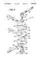
- FIG. 2is an exploded isometric view of the clamp assembly of FIG. 1;
- FIG. 3is a top plan view of the clamp assembly of FIG. 1 with surgical retractors mounted along the extended portions of the support rods;
- FIG. 4is an elevation view of the clamp assembly of FIG. 1;
- FIG. 6is a cross-sectional elevation view of the clamp assembly taken along line 6--6 of FIG. 3.
- FIGS. 1-6a clamp assembly 10 securing a pair of retractor support rods 12 and 14 in a split wishbone configuration to a cylindrical free end of an extension 16 which is rigidly fixed to an operating table (not shown).
- Assembly 10includes outer and intermediate clamping disks 18 and 20 coaxially secured on a clamp base 22 by a bolt 24 and a T-shaped fitting 26.
- Fitting 26includes a cylindrical stem 26a laterally extending from a tubular collar 26b seated in a recess 22a of base 22 and slidable in coaxially aligned holes 28, 30 and 32 in base 22 and disks 18 and 20, respectively.
- the diameters of hole 32 and of a rim 30a of hole 30are less than of hole 28 and correspond to a reduced diameter of the distal end of stem 26a beginning at a shoulder 26c intermediate of the ends in order to ensure proper assembly of disks 18 and 20 on base 22.
- Collar 26 bdefines a cylindrical passage 34 alignable with cylindrical passages 36a and 36b in base 22 for slidably receiving the end of extension 16.
- Bolt 24extends from outer clamping plate 20 through a captive thrust washer 38 and terminates with a bifurcated end 24a pivotally connected at a pin 40 to a handle 42 for manually tightening fitting 26 in assembly 10.
- a clearance mbetween recess 22a and collar 26b, allows fitting 26 to be tightened by bolt 24 pressing disks 18 and 20 and base 22 together until passages 34, 36a and 36b are frictionally clamped against rotation on extension 16.
- a set screw 44 in body 22extends into bore 36b and engages an annular groove 46 adjacent to the end of extension 16 to prevent removal of extension 16 while allowing assembly 10 to rotate about extension 16 when bolt 24 is loosened.
- Clamping disks 18 and 20further include, respectively, a pair of parallel rectangular channels 48 and 50 facing disk 20 and base 22 on opposite sides of holes 30 and 32 for slidably receiving the proximal ends of rods 12 and 14.
- the other channel of each diskis unoccupied.
- the proximal end of each rodhas top and bottom flat surfaces interchangeably cooperating with channels 48 and 50 to prevent rotation relative to disks 18 and 20.
- the distance between the flat surfaces, contiguous with either disks 18 and 20 or disk 20 and base 22,is slightly greater than the depth of channels 48 and 50 to insure proper clamping on rods 12 and 14. That is, as fitting 26 is tightened drawing extension 16 against base 22, rods 12 and 14 are simultaneously clamped in selected ones of channels 48 and 50.
- the spread between retractor support rods 12 and 14may be indexed to one of four positions.
- a pin 56, press-fitted in disk 18,is radially positioned to register with one of four angularly spaced holes 58 in disk 20.
- the position of pin 56is indicated by a cursor 52 and scale 54 inscribed on the side edges of disks 18 and 20, respectively.
- rods 12 and 14are shown, with retractors 60, installed in parallel with pin 52 in the second hole 54 from the right (FIG. 5), cursor 52 being aligned with the long or cardinal graduation on scale 54.
- the spreadis about 15 inches at the distal ends of rods 12 and 14.
- Indexing cursor 52 to the short line to the right of the cardinal graduationcauses rods 12 and 14 to "toe-in” with a spread of approximately 121/2 inches.
- Indexing cursor 52 to the short lines on the left of the cardinal graduationproduces spreads of 171/2 inches and 20 inches.
- fitting 26is first inserted in base 22 and both are slipped on the free end of operating table extension 16 and restrained from axial movement by extending set screw 44 into groove 46. Disks 20 and 18 are then stacked on base 22, and bolt 24 with washer 38 is loosely threaded into stem 26a. As this occurs, pin 56 registers with the hole 58 associated the desired indexed position of cursor 52 and scale 54. Bolt 24 may now be fully tightened with handle 42 thereby simultaneously clamping assembly 10 to extension 16 and rods 12 and 14 in their respective positions.
- a clamp assemblyis provided which is particularly useful with surgical retractor apparatus for adjusting the spread between retractor support rods, which allows operating personnel closer access to the surgical site, and which provide greater use for different size patients and surgical incisions.
- the assemblyenables an operator to fix simultaneously the positions of the support rods relative to each other and to the operating table without the assistance of other persons.
- the assemblyis constructed of relatively few parts which are easily disassembled for cleaning and sterilizing.
Landscapes
- Engineering & Computer Science (AREA)
- General Engineering & Computer Science (AREA)
- Health & Medical Sciences (AREA)
- Mechanical Engineering (AREA)
- Surgery (AREA)
- Life Sciences & Earth Sciences (AREA)
- Molecular Biology (AREA)
- Medical Informatics (AREA)
- Heart & Thoracic Surgery (AREA)
- Animal Behavior & Ethology (AREA)
- General Health & Medical Sciences (AREA)
- Public Health (AREA)
- Veterinary Medicine (AREA)
- Biomedical Technology (AREA)
- Nuclear Medicine, Radiotherapy & Molecular Imaging (AREA)
- Surgical Instruments (AREA)
Abstract
Description
Claims (13)
Priority Applications (1)
| Application Number | Priority Date | Filing Date | Title |
|---|---|---|---|
| US07/394,673US4993862A (en) | 1989-08-16 | 1989-08-16 | Clamp assembly for surgical retractor support |
Applications Claiming Priority (1)
| Application Number | Priority Date | Filing Date | Title |
|---|---|---|---|
| US07/394,673US4993862A (en) | 1989-08-16 | 1989-08-16 | Clamp assembly for surgical retractor support |
Publications (1)
| Publication Number | Publication Date |
|---|---|
| US4993862Atrue US4993862A (en) | 1991-02-19 |
Family
ID=23559941
Family Applications (1)
| Application Number | Title | Priority Date | Filing Date |
|---|---|---|---|
| US07/394,673Expired - LifetimeUS4993862A (en) | 1989-08-16 | 1989-08-16 | Clamp assembly for surgical retractor support |
Country Status (1)
| Country | Link |
|---|---|
| US (1) | US4993862A (en) |
Cited By (50)
| Publication number | Priority date | Publication date | Assignee | Title |
|---|---|---|---|---|
| EP0698374A3 (en)* | 1994-07-19 | 1996-03-13 | Int Surgical Tech Inc | |
| US5730757A (en)* | 1996-02-20 | 1998-03-24 | Cardiothoracic Systems, Inc. | Access platform for internal mammary dissection |
| WO1998027869A1 (en)* | 1996-12-23 | 1998-07-02 | University Of Massachusetts | Minimally invasive surgical apparatus and method |
| US5944736A (en)* | 1996-02-20 | 1999-08-31 | Cardiothoracic Systems, Inc. | Access platform for internal mammary dissection |
| US6017304A (en)* | 1994-08-31 | 2000-01-25 | Vierra; Mark A. | Device and method for isolating a surgical site |
| US6085749A (en)* | 1996-02-26 | 2000-07-11 | Ethicon Endo-Surgery, Inc. | Articulating guide arm for medical applications |
| US6161982A (en)* | 1998-04-22 | 2000-12-19 | Splined Tools Corporation | Assembly with a sealed coupler |
| US6190311B1 (en) | 1997-05-02 | 2001-02-20 | Cardiothoracic Systems, Inc. | Retractor and instrument platform for a less invasive cardiovascular surgical procedure |
| US6199556B1 (en) | 1998-05-01 | 2001-03-13 | Cardiothoracic Systems, Inc. | Xyphoid access for cardiac surgical procedures |
| US6231506B1 (en) | 1999-05-04 | 2001-05-15 | Cardiothoracic Systems, Inc. | Method and apparatus for creating a working opening through an incision |
| US6283912B1 (en) | 1999-05-04 | 2001-09-04 | Cardiothoracic Systems, Inc. | Surgical retractor platform blade apparatus |
| US6290644B1 (en) | 1996-02-20 | 2001-09-18 | Cardiothoracic Systems, Inc. | Surgical instruments and procedures for stabilizing a localized portion of a beating heart |
| US6296312B1 (en) | 1995-02-21 | 2001-10-02 | Neutral Posture Ergonomics, Inc. | Armrest assembly |
| US6315717B1 (en) | 1996-02-20 | 2001-11-13 | Cardiothoracic Systems, Inc. | Surgical instruments for stabilizing the beating heart during coronary artery bypass graft surgery |
| US6394951B1 (en) | 1996-02-20 | 2002-05-28 | Cardiothoracic Systems, Inc. | Surgical instruments and procedures for stabilizing the beating heart during coronary artery bypass graft surgery |
| US20020065451A1 (en)* | 1997-09-17 | 2002-05-30 | Spence Paul A. | Device to permit offpump beating heart coronary bypass surgery |
| US6406424B1 (en) | 1999-09-16 | 2002-06-18 | Williamson, Iv Warren P. | Tissue stabilizer having an articulating lift element |
| US20030009081A1 (en)* | 1999-07-08 | 2003-01-09 | Chase Medical, Lp | Device and method for isolating a surface of a beating heart during surgery |
| US6511416B1 (en) | 1999-08-03 | 2003-01-28 | Cardiothoracic Systems, Inc. | Tissue stabilizer and methods of use |
| WO2003014580A1 (en)* | 2001-08-03 | 2003-02-20 | Norbert Basler | System, clamping element and counter-element for the connection of profiled elements |
| US20030094180A1 (en)* | 1995-04-10 | 2003-05-22 | Benetti Frederico J. | Method for coronary artery bypass |
| GB2382306A (en)* | 2001-09-27 | 2003-05-28 | Cls Medical Ltd | A clamp for simultaneously clamping both a clamp support bar and a surgical retractor into position |
| US6626830B1 (en) | 1999-05-04 | 2003-09-30 | Cardiothoracic Systems, Inc. | Methods and devices for improved tissue stabilization |
| US6645141B1 (en)* | 2002-06-27 | 2003-11-11 | Boss Instruments, Ltd. | Surgical retractor apparatus |
| US20040002633A1 (en)* | 2002-06-27 | 2004-01-01 | Burns Phillips | Surgical retractor apparatus |
| US6685632B1 (en) | 1999-05-04 | 2004-02-03 | Cardiothoracic Systems, Inc. | Surgical instruments for accessing and stabilizing a localized portion of a beating heart |
| US20040092798A1 (en)* | 1997-09-17 | 2004-05-13 | Spence Paul A. | Device to permit offpump beating heart coronary bypass surgery |
| US6746467B1 (en) | 1996-02-20 | 2004-06-08 | Cardio Thoracic Systems, Inc. | Access platform for internal mammary dissection |
| US6758808B2 (en) | 2001-01-24 | 2004-07-06 | Cardiothoracic System, Inc. | Surgical instruments for stabilizing a localized portion of a beating heart |
| US6761292B1 (en) | 2002-08-13 | 2004-07-13 | Elyse L. Newman | Device adapted for use in donning a ski boot and method of using said device |
| US6840141B2 (en) | 2003-01-09 | 2005-01-11 | Brian T. Cole | Radial indexing head tool with floating splined pin |
| US20050010197A1 (en)* | 2003-07-08 | 2005-01-13 | Liming Lau | Organ manipulator apparatus |
| US6852075B1 (en) | 1996-02-20 | 2005-02-08 | Cardiothoracic Systems, Inc. | Surgical devices for imposing a negative pressure to stabilize cardiac tissue during surgery |
| US20050148824A1 (en)* | 2003-12-30 | 2005-07-07 | Morejohn Dwight P. | Transabdominal surgery system |
| US20050148822A1 (en)* | 2003-12-30 | 2005-07-07 | Willis Geoffrey H. | Organ manipulator and positioner and methods of using the same |
| US20050148825A1 (en)* | 1997-09-17 | 2005-07-07 | Spence Paul A. | Device to permit offpump beating heart coronary bypass surgery |
| US20050178249A1 (en)* | 2003-01-09 | 2005-08-18 | Cole Charles A. | Radial indexing head tool with floating splined pin |
| US20070088203A1 (en)* | 2005-05-25 | 2007-04-19 | Liming Lau | Surgical assemblies and methods for visualizing and performing surgical procedures in reduced-access surgical sites |
| US20080203644A1 (en)* | 2007-02-28 | 2008-08-28 | Dasilva Manuel F | Operating table support clamp |
| USD578217S1 (en)* | 2006-02-13 | 2008-10-07 | The LeVahn Intellectual Property Holding Company, LLC | Surgical clamp handle |
| US20100019214A1 (en)* | 2008-07-21 | 2010-01-28 | Indexable Tools, LLC | Hammer and crowbar with adjustable claw |
| US20110052313A1 (en)* | 2006-06-08 | 2011-03-03 | Ivan Boruta | Biaxial joint |
| US7931590B2 (en) | 2002-10-29 | 2011-04-26 | Maquet Cardiovascular Llc | Tissue stabilizer and methods of using the same |
| US20110250009A1 (en)* | 2010-04-08 | 2011-10-13 | Loren Swanson | Method and Apparatus for Reconfigurable Furniture |
| US8083664B2 (en) | 2005-05-25 | 2011-12-27 | Maquet Cardiovascular Llc | Surgical stabilizers and methods for use in reduced-access surgical sites |
| US20140309500A1 (en)* | 2013-04-12 | 2014-10-16 | Akron General Partners, Inc. | Self-retaining retractor |
| US9022998B2 (en) | 2010-02-26 | 2015-05-05 | Maquet Cardiovascular Llc | Blower instrument, apparatus and methods of using |
| US9078635B2 (en)* | 2012-02-02 | 2015-07-14 | Tedan Surgical Innovations, Llc | Anterior hip replacement retractor assembly |
| US9655605B2 (en) | 2010-06-14 | 2017-05-23 | Maquet Cardiovascular Llc | Surgical instruments, systems and methods of use |
| US10792449B2 (en) | 2017-10-03 | 2020-10-06 | Breathe Technologies, Inc. | Patient interface with integrated jet pump |
Citations (8)
| Publication number | Priority date | Publication date | Assignee | Title |
|---|---|---|---|---|
| US369143A (en)* | 1887-08-30 | Compound swiveling and clamping joint mechanism | ||
| US1469448A (en)* | 1922-04-03 | 1923-10-02 | Elmer S Seavey | Flexible joint |
| GB630409A (en)* | 1947-10-23 | 1949-10-12 | W & J George And Becker Ltd | Improvements in clamping means for apparatus for use in scientific demonstrations |
| US3357726A (en)* | 1966-11-10 | 1967-12-12 | Theodore C Gabrielson | Clamping device |
| US4339844A (en)* | 1978-06-30 | 1982-07-20 | Caterpillar Tractor Co. | Assembly for holding open a door or the like |
| US4426071A (en)* | 1981-02-13 | 1984-01-17 | Landstingens Inkopscentral, Lic, Ekonomisk Forening | Leg supporting device for obstetrical tables |
| US4617916A (en)* | 1984-11-08 | 1986-10-21 | Minnesota Scientific, Inc. | Retractor apparatus |
| US4747569A (en)* | 1987-07-13 | 1988-05-31 | Hoshino Gakki Co., Ltd. | Support head for a musical instrument holder or the like |
- 1989
- 1989-08-16USUS07/394,673patent/US4993862A/ennot_activeExpired - Lifetime
Patent Citations (8)
| Publication number | Priority date | Publication date | Assignee | Title |
|---|---|---|---|---|
| US369143A (en)* | 1887-08-30 | Compound swiveling and clamping joint mechanism | ||
| US1469448A (en)* | 1922-04-03 | 1923-10-02 | Elmer S Seavey | Flexible joint |
| GB630409A (en)* | 1947-10-23 | 1949-10-12 | W & J George And Becker Ltd | Improvements in clamping means for apparatus for use in scientific demonstrations |
| US3357726A (en)* | 1966-11-10 | 1967-12-12 | Theodore C Gabrielson | Clamping device |
| US4339844A (en)* | 1978-06-30 | 1982-07-20 | Caterpillar Tractor Co. | Assembly for holding open a door or the like |
| US4426071A (en)* | 1981-02-13 | 1984-01-17 | Landstingens Inkopscentral, Lic, Ekonomisk Forening | Leg supporting device for obstetrical tables |
| US4617916A (en)* | 1984-11-08 | 1986-10-21 | Minnesota Scientific, Inc. | Retractor apparatus |
| US4747569A (en)* | 1987-07-13 | 1988-05-31 | Hoshino Gakki Co., Ltd. | Support head for a musical instrument holder or the like |
Cited By (143)
| Publication number | Priority date | Publication date | Assignee | Title |
|---|---|---|---|---|
| EP0698374A3 (en)* | 1994-07-19 | 1996-03-13 | Int Surgical Tech Inc | |
| US7025722B2 (en) | 1994-08-31 | 2006-04-11 | Heartport, Inc. | Device and method for isolating a surgical site |
| US20040254425A1 (en)* | 1994-08-31 | 2004-12-16 | Vierra Mark A. | Device and method for isolating a surgical site |
| US6821247B2 (en) | 1994-08-31 | 2004-11-23 | Heartport, Inc. | Device and method for isolating a surgical site |
| US6017304A (en)* | 1994-08-31 | 2000-01-25 | Vierra; Mark A. | Device and method for isolating a surgical site |
| US6139492A (en)* | 1994-08-31 | 2000-10-31 | Heartport, Inc. | Device and method for isolating a surgical site |
| US6149583A (en)* | 1994-08-31 | 2000-11-21 | Heartport, Inc. | Device and method for isolating a surgical site |
| US6482151B1 (en) | 1994-08-31 | 2002-11-19 | Heartport, Inc. | Method of performing a procedure on a coronary artery |
| US6296312B1 (en) | 1995-02-21 | 2001-10-02 | Neutral Posture Ergonomics, Inc. | Armrest assembly |
| US7219671B2 (en) | 1995-04-10 | 2007-05-22 | Cardiothoracic Systems, Inc. | Method for coronary artery bypass |
| US20030094180A1 (en)* | 1995-04-10 | 2003-05-22 | Benetti Frederico J. | Method for coronary artery bypass |
| US7497824B2 (en) | 1996-02-20 | 2009-03-03 | Maquet Cardiovasculer, Llc | Surgical devices for imposing a negative pressure to stabilize cardiac tissue during surgery |
| US7585277B2 (en) | 1996-02-20 | 2009-09-08 | Maquet Cardiovascular Llc | Surgical instruments and procedures for stabilizing the beating heart during coronary artery bypass graft surgery |
| US6290644B1 (en) | 1996-02-20 | 2001-09-18 | Cardiothoracic Systems, Inc. | Surgical instruments and procedures for stabilizing a localized portion of a beating heart |
| US5730757A (en)* | 1996-02-20 | 1998-03-24 | Cardiothoracic Systems, Inc. | Access platform for internal mammary dissection |
| US6315717B1 (en) | 1996-02-20 | 2001-11-13 | Cardiothoracic Systems, Inc. | Surgical instruments for stabilizing the beating heart during coronary artery bypass graft surgery |
| US6743169B1 (en) | 1996-02-20 | 2004-06-01 | Cardiothoracic Systems, Inc. | Surgical instruments and procedures for stabilizing the beating heart during coronary artery bypass graft surgery |
| US7056287B2 (en) | 1996-02-20 | 2006-06-06 | Cardiothoracic Systems, Inc. | Surgical instruments and procedures for stabilizing the beating heart during coronary artery bypass graft surgery |
| US8277476B2 (en) | 1996-02-20 | 2012-10-02 | Maguet Cardiovascular LLC | Surgical instruments and procedures for stabilizing the beating heart during coronary artery bypass graft |
| US6394951B1 (en) | 1996-02-20 | 2002-05-28 | Cardiothoracic Systems, Inc. | Surgical instruments and procedures for stabilizing the beating heart during coronary artery bypass graft surgery |
| US6893391B2 (en) | 1996-02-20 | 2005-05-17 | Cardiothoracic Systems, Inc. | Surgical devices for imposing a negative pressure to stabilize cardiac tissue during surgery |
| US20050038316A1 (en)* | 1996-02-20 | 2005-02-17 | Taylor Charles S. | Surgical devices for imposing a negative pressure to stabilize cardiac tissue during surgery |
| US20020111537A1 (en)* | 1996-02-20 | 2002-08-15 | Taylor Charles S. | Surgical instruments and procedures for stabilizing the beating heart during coronary artery bypass graft surgery |
| US20050033111A1 (en)* | 1996-02-20 | 2005-02-10 | Taylor Charles S. | Surgical devices for imposing a negative pressure to stabilize cardiac tissue during surgery |
| US20110172568A1 (en)* | 1996-02-20 | 2011-07-14 | Taylor Charles S | Surgical Devices for Imposing a Negative Pressure to Stabilize the Cardiac Tissue During Surgery |
| US6478734B1 (en) | 1996-02-20 | 2002-11-12 | Cardiothoracic Systems, Inc. | Access platform for internal mammary dissection |
| US6852075B1 (en) | 1996-02-20 | 2005-02-08 | Cardiothoracic Systems, Inc. | Surgical devices for imposing a negative pressure to stabilize cardiac tissue during surgery |
| US6746467B1 (en) | 1996-02-20 | 2004-06-08 | Cardio Thoracic Systems, Inc. | Access platform for internal mammary dissection |
| US7909846B1 (en) | 1996-02-20 | 2011-03-22 | Maquet Cardiovascular Llc | Access platform for internal mammary dissection |
| US7699774B1 (en) | 1996-02-20 | 2010-04-20 | Maquet Cardiovascular Llc | Access platform for internal mammary dissection |
| US20080114201A1 (en)* | 1996-02-20 | 2008-05-15 | Taylor Charles S | Surgical devices for imposing a negative pressure to stabilize the cardiac tissue during surgery |
| US20030060686A1 (en)* | 1996-02-20 | 2003-03-27 | Taylor Charles S. | Access platform for internal mammary dissection |
| US7335158B2 (en) | 1996-02-20 | 2008-02-26 | Cardiothoracic Systems, Inc. | Surgical devices for imposing a negative pressure to stabilize the cardiac tissue during surgery |
| US20070055108A1 (en)* | 1996-02-20 | 2007-03-08 | Taylor Charles S | Surgical instruments and procedures for stabilizing the beating heart during coronary artery bypass graft surgery |
| US6602189B1 (en) | 1996-02-20 | 2003-08-05 | Cardiothoracic Systems, Inc. | Access platform for internal mammary dissection |
| US20040087834A1 (en)* | 1996-02-20 | 2004-05-06 | Benetti Federico J. | Surgical instruments and procedures for stabilizing the beating heart during coronary artery bypass graft surgery |
| US5944736A (en)* | 1996-02-20 | 1999-08-31 | Cardiothoracic Systems, Inc. | Access platform for internal mammary dissection |
| US20040230099A1 (en)* | 1996-02-20 | 2004-11-18 | Taylor Charles S. | Surgical instruments and procedures for stabilizing the beating heart during coronary artery bypass graft surgery |
| US6656113B2 (en) | 1996-02-20 | 2003-12-02 | Cardiothoracic System, Inc. | Surgical instruments and procedures for stabilizing a localized portion of a beating heart |
| US7485090B2 (en) | 1996-02-20 | 2009-02-03 | Maquet Cardiovascular Llc | Surgical devices for imposing a negative pressure to stabilize cardiac tissue during surgery |
| US6673013B2 (en) | 1996-02-20 | 2004-01-06 | Cardiothoracic Systems, Inc. | Surgical instruments and procedures for stabilizing the beating heart during coronary artery bypass graft surgery |
| US8382654B2 (en) | 1996-02-20 | 2013-02-26 | Maquet Cardiovascular Llc | Surgical devices for imposing a negative pressure to stabilize the cardiac tissue during surgery |
| US7288065B1 (en) | 1996-02-20 | 2007-10-30 | Cardiothoracic System, Inc. | Access platform for internal mammary dissection |
| US6701930B2 (en) | 1996-02-20 | 2004-03-09 | Cardiothoracic Systems, Inc. | Surgical instruments and procedures for stabilizing the beating heart during coronary artery bypass graft surgery |
| US20070149844A1 (en)* | 1996-02-20 | 2007-06-28 | Benetti Federico J | Surgical devices for imposing a negative pressure to stabilize the cardiac tissue during surgery |
| US6085749A (en)* | 1996-02-26 | 2000-07-11 | Ethicon Endo-Surgery, Inc. | Articulating guide arm for medical applications |
| US6488030B1 (en) | 1996-02-26 | 2002-12-03 | Ethicon Endo-Surgery, Inc. | Articulating guide arm for medical applications |
| WO1998027869A1 (en)* | 1996-12-23 | 1998-07-02 | University Of Massachusetts | Minimally invasive surgical apparatus and method |
| US6322500B1 (en) | 1996-12-23 | 2001-11-27 | University Of Massachusetts | Minimally invasive surgical apparatus |
| US6190311B1 (en) | 1997-05-02 | 2001-02-20 | Cardiothoracic Systems, Inc. | Retractor and instrument platform for a less invasive cardiovascular surgical procedure |
| US7476199B2 (en) | 1997-09-17 | 2009-01-13 | Maquet Cardiovascular, Llc. | Device to permit offpump beating heart coronary bypass surgery |
| US6969349B1 (en) | 1997-09-17 | 2005-11-29 | Origin Medsystem, Inc. | Device to permit offpump beating heart coronary bypass surgery |
| US20050148825A1 (en)* | 1997-09-17 | 2005-07-07 | Spence Paul A. | Device to permit offpump beating heart coronary bypass surgery |
| US7377895B2 (en) | 1997-09-17 | 2008-05-27 | Origin Medsystems, Inc. | Device to permit offpump beating heart coronary bypass surgery |
| US20040092798A1 (en)* | 1997-09-17 | 2004-05-13 | Spence Paul A. | Device to permit offpump beating heart coronary bypass surgery |
| US7404792B2 (en) | 1997-09-17 | 2008-07-29 | Origin Medsystems, Inc. | Device to permit offpump beating heart coronary bypass surgery |
| US20040138533A1 (en)* | 1997-09-17 | 2004-07-15 | Spence Paul A. | Device to permit offpump beating heart coronary bypass surgery |
| US20070179344A1 (en)* | 1997-09-17 | 2007-08-02 | Spence Paul A | Device to permit offpump beating heart coronary bypass surgery |
| US6705988B2 (en) | 1997-09-17 | 2004-03-16 | Origin Medsystems, Inc. | Device to permit offpump beating heart coronary bypass surgery |
| US7476196B2 (en) | 1997-09-17 | 2009-01-13 | Maquet Cardiovascular, Llc | Device to permit offpump beating heart coronary bypass surgery |
| US20040225195A1 (en)* | 1997-09-17 | 2004-11-11 | Spence Paul A. | Device to permit offpump beating heart coronary bypass surgery |
| US6743170B1 (en) | 1997-09-17 | 2004-06-01 | Cardiothoracic Systems, Inc. | Device to permit offpump beating heart coronary bypass surgery |
| US20090099411A1 (en)* | 1997-09-17 | 2009-04-16 | Spence Paul A | Device to permit offpump beating heart coronary bypass surgery |
| US8753266B2 (en) | 1997-09-17 | 2014-06-17 | Maquet Cardiovascular Llc | Device to permit offpump beating heart coronary bypass surgery |
| US7195591B2 (en) | 1997-09-17 | 2007-03-27 | Origin Medsystems, Inc. | Device to permit offpump beating heart coronary bypass surgery |
| US20090099412A1 (en)* | 1997-09-17 | 2009-04-16 | Spence Paul A | Device to Permit Offpump Beating Heart Coronary Bypass Surgery |
| US8317695B2 (en) | 1997-09-17 | 2012-11-27 | Maquet Cardiovascular Llc | Device to permit offpump beating heart coronary bypass surgery |
| US20020161285A1 (en)* | 1997-09-17 | 2002-10-31 | Spence Paul A. | Device to permit offpump beating heart coronary bypass surgery |
| US8162817B2 (en) | 1997-09-17 | 2012-04-24 | Maquet Cardiovascular Llc | Device to permit offpump beating heart coronary bypass surgery |
| US20020065451A1 (en)* | 1997-09-17 | 2002-05-30 | Spence Paul A. | Device to permit offpump beating heart coronary bypass surgery |
| US6161982A (en)* | 1998-04-22 | 2000-12-19 | Splined Tools Corporation | Assembly with a sealed coupler |
| US6199556B1 (en) | 1998-05-01 | 2001-03-13 | Cardiothoracic Systems, Inc. | Xyphoid access for cardiac surgical procedures |
| US6736774B2 (en) | 1998-05-01 | 2004-05-18 | Cardiothoracic Systems, Inc. | Xyphoid access for cardiac surgical procedures |
| US6626830B1 (en) | 1999-05-04 | 2003-09-30 | Cardiothoracic Systems, Inc. | Methods and devices for improved tissue stabilization |
| US20100210916A1 (en)* | 1999-05-04 | 2010-08-19 | Hu Lawrence W | Surgical Instruments for Accessing and Stabilizing a Localized Portion of a Beating Heart |
| US9498198B2 (en) | 1999-05-04 | 2016-11-22 | Maquet Cardiovascular, Llc | Surgical instruments for accessing and stabilizing a localized portion of a beating heart |
| US6231506B1 (en) | 1999-05-04 | 2001-05-15 | Cardiothoracic Systems, Inc. | Method and apparatus for creating a working opening through an incision |
| US6283912B1 (en) | 1999-05-04 | 2001-09-04 | Cardiothoracic Systems, Inc. | Surgical retractor platform blade apparatus |
| US6331158B1 (en) | 1999-05-04 | 2001-12-18 | Cardiothoracic Systems, Inc. | Surgical retractor apparatus for operating on the heart through an incision |
| US20020004628A1 (en)* | 1999-05-04 | 2002-01-10 | Hu Lawrence W. | Surgical retractor platform blade apparatus |
| US20040092799A1 (en)* | 1999-05-04 | 2004-05-13 | Hu Lawrence W. | Method and apparatus for creating a working opening through an incision |
| US6685632B1 (en) | 1999-05-04 | 2004-02-03 | Cardiothoracic Systems, Inc. | Surgical instruments for accessing and stabilizing a localized portion of a beating heart |
| US7220228B2 (en) | 1999-05-04 | 2007-05-22 | Cardiothoracic System, Inc. | Surgical retractor blade and system |
| US6652454B2 (en) | 1999-05-04 | 2003-11-25 | Lawrence W. Hu | Method and apparatus for creating a working opening through an incision |
| US20040030223A1 (en)* | 1999-05-04 | 2004-02-12 | Calafiore Antonio M. | Method and devices for improved tissue stabilization |
| US7736307B2 (en) | 1999-05-04 | 2010-06-15 | Maquet Cardiovascular Llc | Surgical instruments for accessing and stabilizing a localized portion of a beating heart |
| US7238155B2 (en) | 1999-05-04 | 2007-07-03 | Cardiothoracic Systems, Inc. | Method and apparatus for creating a working opening through an incision |
| US20070156027A1 (en)* | 1999-05-04 | 2007-07-05 | Hu Lawrence W | Surgical retractor platform blade apparatus |
| US20030009081A1 (en)* | 1999-07-08 | 2003-01-09 | Chase Medical, Lp | Device and method for isolating a surface of a beating heart during surgery |
| US6740029B2 (en) | 1999-07-08 | 2004-05-25 | Chase Medical, L.P. | Device and method for isolating a surface of a beating heart during surgery |
| US6511416B1 (en) | 1999-08-03 | 2003-01-28 | Cardiothoracic Systems, Inc. | Tissue stabilizer and methods of use |
| US20090137865A1 (en)* | 1999-08-03 | 2009-05-28 | Green Ii Harry Leonard | Tissue Stabilizer and Methods of Use |
| US7503891B2 (en) | 1999-08-03 | 2009-03-17 | Maquet Cardiovascular, Llc | Tissue stabilizer and methods of use |
| US7326177B2 (en) | 1999-09-16 | 2008-02-05 | Cardiothoracic Systems, Inc. | Tissue stabilizer having an articulating lift element |
| US20020165434A1 (en)* | 1999-09-16 | 2002-11-07 | Williamson Warren P. | Tissue stabilizer having an articulating lift element |
| US6406424B1 (en) | 1999-09-16 | 2002-06-18 | Williamson, Iv Warren P. | Tissue stabilizer having an articulating lift element |
| US6758808B2 (en) | 2001-01-24 | 2004-07-06 | Cardiothoracic System, Inc. | Surgical instruments for stabilizing a localized portion of a beating heart |
| CN1317992C (en)* | 2001-08-03 | 2007-05-30 | 诺贝特·巴斯勒 | System for connecting profile elements, clamping element and mating element |
| WO2003014580A1 (en)* | 2001-08-03 | 2003-02-20 | Norbert Basler | System, clamping element and counter-element for the connection of profiled elements |
| US20040213631A1 (en)* | 2001-08-03 | 2004-10-28 | Norbert Basler | System, clamping element and counter-element for the connector of profiled elements |
| US7325997B2 (en) | 2001-08-03 | 2008-02-05 | Norbert Basler | System, clamping element and counter-element for the connector of profiled elements |
| RU2317764C2 (en)* | 2001-08-03 | 2008-02-27 | Норберт Баслер | System, clamping member and locking member for connection of profiled members |
| GB2382306B (en)* | 2001-09-27 | 2004-11-10 | Cls Medical Ltd | Surgical retractor beam clamp |
| GB2382306A (en)* | 2001-09-27 | 2003-05-28 | Cls Medical Ltd | A clamp for simultaneously clamping both a clamp support bar and a surgical retractor into position |
| US20040002633A1 (en)* | 2002-06-27 | 2004-01-01 | Burns Phillips | Surgical retractor apparatus |
| US6790177B2 (en)* | 2002-06-27 | 2004-09-14 | Boss Instruments, Ltd. | Surgical retractor apparatus |
| US6645141B1 (en)* | 2002-06-27 | 2003-11-11 | Boss Instruments, Ltd. | Surgical retractor apparatus |
| US6761292B1 (en) | 2002-08-13 | 2004-07-13 | Elyse L. Newman | Device adapted for use in donning a ski boot and method of using said device |
| EP1551600A4 (en)* | 2002-10-16 | 2008-07-16 | Boss Instr Ltd | Surgical retractor apparatus |
| WO2004035269A1 (en)* | 2002-10-16 | 2004-04-29 | Boss Instruments, Ltd. | Surgical retractor apparatus |
| US7931590B2 (en) | 2002-10-29 | 2011-04-26 | Maquet Cardiovascular Llc | Tissue stabilizer and methods of using the same |
| US20050178249A1 (en)* | 2003-01-09 | 2005-08-18 | Cole Charles A. | Radial indexing head tool with floating splined pin |
| US7156003B2 (en) | 2003-01-09 | 2007-01-02 | Cole Charles A | Radial indexing head tool with floating splined pin |
| US6840141B2 (en) | 2003-01-09 | 2005-01-11 | Brian T. Cole | Radial indexing head tool with floating splined pin |
| US20050010197A1 (en)* | 2003-07-08 | 2005-01-13 | Liming Lau | Organ manipulator apparatus |
| US10383612B2 (en) | 2003-07-08 | 2019-08-20 | Maquet Cardiovascular Llc | Organ manipulator apparatus |
| US9402608B2 (en) | 2003-07-08 | 2016-08-02 | Maquet Cardiovascular Llc | Organ manipulator apparatus |
| US8641598B2 (en) | 2003-07-08 | 2014-02-04 | Maquet Cardiovascular Llc | Organ manipulator apparatus |
| US7479104B2 (en) | 2003-07-08 | 2009-01-20 | Maquet Cardiovascular, Llc | Organ manipulator apparatus |
| US20090299131A1 (en)* | 2003-07-08 | 2009-12-03 | Green Ii Harry Leonard | Organ Manipulator Apparatus |
| US20050148824A1 (en)* | 2003-12-30 | 2005-07-07 | Morejohn Dwight P. | Transabdominal surgery system |
| US20050148822A1 (en)* | 2003-12-30 | 2005-07-07 | Willis Geoffrey H. | Organ manipulator and positioner and methods of using the same |
| US7179224B2 (en) | 2003-12-30 | 2007-02-20 | Cardiothoracic Systems, Inc. | Organ manipulator and positioner and methods of using the same |
| US20070088203A1 (en)* | 2005-05-25 | 2007-04-19 | Liming Lau | Surgical assemblies and methods for visualizing and performing surgical procedures in reduced-access surgical sites |
| US8083664B2 (en) | 2005-05-25 | 2011-12-27 | Maquet Cardiovascular Llc | Surgical stabilizers and methods for use in reduced-access surgical sites |
| USD578217S1 (en)* | 2006-02-13 | 2008-10-07 | The LeVahn Intellectual Property Holding Company, LLC | Surgical clamp handle |
| US20110052313A1 (en)* | 2006-06-08 | 2011-03-03 | Ivan Boruta | Biaxial joint |
| US20080203644A1 (en)* | 2007-02-28 | 2008-08-28 | Dasilva Manuel F | Operating table support clamp |
| US7686267B2 (en) | 2007-02-28 | 2010-03-30 | Dasilva Manuel F | Operating table support clamp |
| US20100019214A1 (en)* | 2008-07-21 | 2010-01-28 | Indexable Tools, LLC | Hammer and crowbar with adjustable claw |
| US8424845B2 (en) | 2008-07-21 | 2013-04-23 | Indexable Tools, LLC | Hammer and crowbar with adjustable claw |
| US9662434B2 (en) | 2010-02-26 | 2017-05-30 | Maquet Cardiovascular Llc | Blower instrument, apparatus and methods of using |
| US9022998B2 (en) | 2010-02-26 | 2015-05-05 | Maquet Cardiovascular Llc | Blower instrument, apparatus and methods of using |
| US20110250009A1 (en)* | 2010-04-08 | 2011-10-13 | Loren Swanson | Method and Apparatus for Reconfigurable Furniture |
| US9655605B2 (en) | 2010-06-14 | 2017-05-23 | Maquet Cardiovascular Llc | Surgical instruments, systems and methods of use |
| US10398422B2 (en) | 2010-06-14 | 2019-09-03 | Maquet Cardiovascular Llc | Surgical instruments, systems and methods of use |
| US11284872B2 (en) | 2010-06-14 | 2022-03-29 | Maquet Cardiovascular Llc | Surgical instruments, systems and methods of use |
| US12004732B2 (en) | 2010-06-14 | 2024-06-11 | Maquet Cardiovascular Llc | Surgical instruments, systems and methods of use |
| US9078635B2 (en)* | 2012-02-02 | 2015-07-14 | Tedan Surgical Innovations, Llc | Anterior hip replacement retractor assembly |
| US20140309500A1 (en)* | 2013-04-12 | 2014-10-16 | Akron General Partners, Inc. | Self-retaining retractor |
| US9662101B2 (en)* | 2013-04-12 | 2017-05-30 | Akron General Partners, Inc. | Self-retaining retractor |
| US10792449B2 (en) | 2017-10-03 | 2020-10-06 | Breathe Technologies, Inc. | Patient interface with integrated jet pump |
| US12017002B2 (en) | 2017-10-03 | 2024-06-25 | Breathe Technologies, Inc. | Patient interface with integrated jet pump |
Similar Documents
| Publication | Publication Date | Title |
|---|---|---|
| US4993862A (en) | Clamp assembly for surgical retractor support | |
| US4971037A (en) | Surgical retractor support | |
| US5020195A (en) | Clamping device for use on a retractor support | |
| US5231974A (en) | Self retaining retractor | |
| US4790314A (en) | Orifice dilator | |
| EP1916952B1 (en) | External fixation system | |
| US4606522A (en) | Position adjustable instrument holder | |
| US4450834A (en) | External fixation device | |
| Greenberg | Self-retaining retractor and handrest system for neurosurgery | |
| US5582612A (en) | Vertebral fixing and retrieving device having centrally two fixation | |
| US4383682A (en) | Vise jaw assembly having an inclineable platform for supporting a workpiece at a selected angle | |
| US4510926A (en) | Support device for medical instruments | |
| EP0811356B1 (en) | Spinal column retaining apparatus | |
| HU181749B (en) | Surgical table for operating hands | |
| EP0126432B2 (en) | Milling tool | |
| WO1992020285A1 (en) | Surgical retractor apparatus with improved clamping device | |
| IE45961B1 (en) | Device for externally exerting a holding action on bone tissues | |
| US5197975A (en) | Radiolucent spine support frame | |
| JPH05146452A (en) | Combining tool to adjustably combine first structural element with second structural element, especially to pipe or rod for locking device | |
| US20030222388A1 (en) | Modular tooling apparatus with tapered locator system | |
| US4041612A (en) | Jaw tensioning device | |
| EP3340958A1 (en) | Device for securing an accessory to an operating table | |
| US2844345A (en) | Tripods and clamps therefor | |
| US5597149A (en) | Clamping base | |
| US2782513A (en) | Geometrical instruments |
Legal Events
| Date | Code | Title | Description |
|---|---|---|---|
| AS | Assignment | Owner name:PILLING COMPANY, PENNSYLVANIA Free format text:ASSIGNMENT OF ASSIGNORS INTEREST.;ASSIGNOR:PELTA, SAMUEL;REEL/FRAME:005148/0615 Effective date:19890809 | |
| STCF | Information on status: patent grant | Free format text:PATENTED CASE | |
| FEPP | Fee payment procedure | Free format text:PAYOR NUMBER ASSIGNED (ORIGINAL EVENT CODE: ASPN); ENTITY STATUS OF PATENT OWNER: LARGE ENTITY | |
| FPAY | Fee payment | Year of fee payment:4 | |
| AS | Assignment | Owner name:TECHNOLOGY HOLDING COMPANY II, DELAWARE Free format text:ASSIGNMENT OF ASSIGNORS INTEREST;ASSIGNOR:PILLING WECK INCORPORATED;REEL/FRAME:007570/0834 Effective date:19941226 | |
| AS | Assignment | Owner name:PILLING WECK INCORPORATED, PENNSYLVANIA Free format text:CHANGE OF NAME;ASSIGNOR:PILLING CO.;REEL/FRAME:007786/0129 Effective date:19940520 | |
| FEPP | Fee payment procedure | Free format text:PAT HLDR NO LONGER CLAIMS SMALL ENT STAT AS SMALL BUSINESS (ORIGINAL EVENT CODE: LSM2); ENTITY STATUS OF PATENT OWNER: LARGE ENTITY | |
| FPAY | Fee payment | Year of fee payment:8 | |
| FPAY | Fee payment | Year of fee payment:12 | |
| AS | Assignment | Owner name:TELEFLEX MEDICAL INCORPORATED, PENNSYLVANIA Free format text:MERGER;ASSIGNOR:TECHNOLOGY HOLDING COMPANY II;REEL/FRAME:049342/0541 Effective date:20190503 |