US4992931A - Data alignment correction apparatus for properly formatting data structures for different computer architectures - Google Patents
Data alignment correction apparatus for properly formatting data structures for different computer architecturesDownload PDFInfo
- Publication number
- US4992931A US4992931AUS07/137,674US13767487AUS4992931AUS 4992931 AUS4992931 AUS 4992931AUS 13767487 AUS13767487 AUS 13767487AUS 4992931 AUS4992931 AUS 4992931A
- Authority
- US
- United States
- Prior art keywords
- alignment
- data
- storage means
- data blocks
- source data
- Prior art date
- Legal status (The legal status is an assumption and is not a legal conclusion. Google has not performed a legal analysis and makes no representation as to the accuracy of the status listed.)
- Expired - Lifetime
Links
Images


Classifications
- G—PHYSICS
- G06—COMPUTING OR CALCULATING; COUNTING
- G06F—ELECTRIC DIGITAL DATA PROCESSING
- G06F9/00—Arrangements for program control, e.g. control units
- G06F9/06—Arrangements for program control, e.g. control units using stored programs, i.e. using an internal store of processing equipment to receive or retain programs
- G06F9/30—Arrangements for executing machine instructions, e.g. instruction decode
- G06F9/30003—Arrangements for executing specific machine instructions
- G06F9/30007—Arrangements for executing specific machine instructions to perform operations on data operands
- G06F9/30025—Format conversion instructions, e.g. Floating-Point to Integer, decimal conversion
- G—PHYSICS
- G06—COMPUTING OR CALCULATING; COUNTING
- G06F—ELECTRIC DIGITAL DATA PROCESSING
- G06F5/00—Methods or arrangements for data conversion without changing the order or content of the data handled
- G—PHYSICS
- G06—COMPUTING OR CALCULATING; COUNTING
- G06F—ELECTRIC DIGITAL DATA PROCESSING
- G06F8/00—Arrangements for software engineering
- G06F8/40—Transformation of program code
- G06F8/41—Compilation
- G06F8/43—Checking; Contextual analysis
- G06F8/433—Dependency analysis; Data or control flow analysis
- G06F8/434—Pointers; Aliasing
Definitions
- the present inventionrelates to a data alignment correction apparatus for performing alignment correction of a data structure in order that it is properly formatted for a different computer architecture.
- the present inventionhas been developed in consideration of the above situation and has as its object to provide a data alignment correction apparatus which can perform alignment correction of a data structure at a high speed by a common processing routine.
- the apparatuscomprises: first storage means for storing a source data structure, second storage means for sequentially storing an object data structure, alignment data storage means for storing alignment data corresponding to the source data structure, the alignment data including a plurality of alignment data blocks each corresponding to one of said source data blocks, and central processor means for selectively reading out said source data blocks from said first storage means, said selection being in accordance with the corresponding alignment data blocks from said alignment data storage means, and for outputting the selected source data blocks to said second storage means for storage as object data blocks in said object data structure.
- the central processorsequentially reads out the alignment data blocks from the alignment data storage section in response to an alignment correction instruction.
- the alignment data blockis a predetermined value
- the source data blockis read out from the first storage section and stored to the second storage section.
- the alignment data blockdoes not match a predetermined value
- the next alignment data blocksis read out from the alignment data storage section without storing the source data element. In this manner, the source data blocks are transferred in accordance with the alignment data blocks, thereby performing alignment correction of the structure.
- alignment correction for a required structurecan be performed at a high speed by a common processing subroutine by merely preparing alignment data, regardless of the type of the structure.
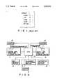
- FIG. 1shows a conventional C language data structure
- FIG. 2is a block diagram of an arrangement of an alignment correction apparatus according to an embodiment of the present invention.
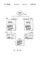
- FIGS. 3A and 3Bare flow charts for explaining an operation of the first embodiment in FIG. 1;
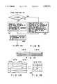
- FIG. 4is a view of alignment data used to perform alignment correction of a structure having a 4-byte boundary into a structure having a 2-byte boundary;
- FIGS. 5A and 5Bare views having the structures of 4- and 2-byte boundaries, respectively, to which the alignment data in FIG. 4 is applied;
- FIG. 6is a view of a modification of the alignment data in FIG. 4;
- FIG. 7is a view of alignment data used to perform alignment correction of a structure of 4-byte boundary in a 32-bit machine into a structure of 1-byte boundary in a 16-bit machine;
- FIGS. 8A and 8Bare views of the structures of 4- and 1-byte boundaries, respectively, to which the alignment data in FIG. 7 is applied;
- FIG. 9is a flow chart for explaining an operation of alignment correction of a structure having a 1-byte boundary in a 16-bit machine into a structure having a 4-byte boundary in a 32-bit machine;
- FIG. 10is a view of the alignment data used in the operation of FIG. 9;
- FIGS. 11A and 11Bare views of the structures having a 4- and 1-byte boundaries to which the alignment data in FIG. 10 is applied.
- FIG. 12is a view for explaining a routine of obtaining an object data structure by alignment processing.
- source data structure storage section 11stores at least one source data structure 20.
- Object data structure storage section 12stores an object data structure 21 which is obtained by correcting the alignment of the source data structure stored in section 11.
- Alignment data storage section 13stores alignment data which corresponds to the alignment relationship between the source and object data structures. The number of alignment data stored in section 13 depends on the number of types and the source data structures.
- the alignment dataincludes bit groups. Each bit group (alignment data block) determines whether a data byte (data block) of the source data structure is to be retained or deleted during the alignment correction procedure. A data byte to be deleted is padding data which is inserted for alignment correction. Each data byte of the source data structure is in 1:1 correspondence with each data bit of the alignment data. Therefore, when the size of the source data structure is 16 bytes, as is shown in FIG. 5A, the alignment data includes 16 bits. In this embodiment, each logic "1" bit of the alignment data represents that the corresponding data byte is to remain after correction, and each logic "0" represents that the data is to be deleted thereafter.
- the data alignment correction apparatusalso includes size register section 14 for storing the byte size value of a source data structure, counter 15 for indicating the location of a byte to be accessed in source data structure, and instruction register section 19 for holding an instruction of an alignment correction routine.
- the alignment correction apparatusfurther includes counter 16 for indicating the location of a byte to be stored in storage section 12, counter 17 for indicating the location of a bit to be accessed in alignment data storage section 13, and CPU 18 for executing a variety of alignment correction instructions. Note that in this embodiment, source data structure, object data structure, and alignment data storage sections 11, 12, and 13, registers 14 and 19, and counters 15 and 17 are allocated in a main memory.
- source data structure storage section 11stores, as a source data structure, the structure shown in FIG. 5A
- size register section 14stores the byte size value of the structure, i.e., "15”
- alignment data storage section 13stores the alignment data shown in FIG. 4.
- step S2fetches an alignment correction instruction from instruction register section 19 and decodes it.
- counters 15 to 17are initialized to, for example, "0".
- the alignment correction instructionis either a delete alignment correction instruction or an insertion alignment correction instruction. If the instruction is a delete alignment correction instruction, step S6 is sequentially executed subsequent to step S4. If the instruction is an insertion alignment correction instruction, step S18 is sequentially executed after step S4.
- step S6If the fetched instruction is a delete alignment instruction, bit 0 of the alignment data in storage section 13, designated by the content of counter 17 is read out in step S6.
- step S8CPU 18 checks whether the readout bit 0 data is logic "1". If Y (YES) in step S8, step S10 is executed. If N (NO) in step S8, step S16 is executed. In this case, since the alignment data is given as shown in FIG. 4, the bit 0 data is logic "1". Therefore, steps S8 and S10 are sequentially executed.
- step S10byte data of the source data structure in storage section 11, designated as by the content of counter 159, is read out.
- the byte datais written in a location of storage section 12 as designated by the content of counter 16.
- the byte data read out from storage section 11remains after correction.
- step S10the contents of counters 15, 16, and 17 are all incremented by "1" in step S12 and advance to the location of the next byte to be read out from source data storage section 11, the location of the next byte to be written to object data storage section 12, and the location of the next bit to be read out from alignment data storage section 17, respectively.
- bit data of the alignment datais logic "0", as is bit 3 data, only counters 15 and 17 are incremented by "1", in step S16.
- the byte data, of the source data structure in storage section 11, as designated by the content of counter 15is deleted after correction.
- step S12 or S16When step S12 or S16 is executed, the content of counter 15 and that of register section 14, i.e., the size value of the source data structure, are fetched 11 and CPU 18 checks whether the content of counter 15 exceeds the size value set in register section 14, in step S14. If N (NO) in step S14, CPU 18 determines that the alignment correction processing with respect to all the byte data of the source data structure is not completed, and the flow returns to step S6.
- the structure shown in FIG. 5Bis generated from its start byte, in units of bytes, in storage section 12.
- CPU 18completes the alignment correction processing. In this manner, the delete alignment correction instruction is executed.
- one data byte of the source data structurecorresponds to one data bit of the alignment data.
- the alignment datacan be reduced by causing 2-byte data of the source data structure to correspond to 1-bit data of the alignment data, as shown in FIG. 6.
- two bytes of source datais one source data block, and counters 15 and 16 are incremented by "2" in step S12 or S16.
- object file B including structure Bis obtained from a source file.
- object file Bcan be obtained at S140 by compiling the source file by compiler B at S120 including alignment correction routine B as described above.
- object file A compiled by compiler A at S110 including alignment correction routine A as described aboveis present at S130, object file C can be obtained at S150 by performing alignment correction processing by alignment correction routine C substantially the same as alignment correction routine B S120.
- step S24 or S30When step S24 or S30 is executed, the content of counter 15 and the content of register section 14, i.e., the size value of the source data structure are read out, and CPU 18 checks whether the content of counter 15 exceeds the size value set in register section 14, in step S26. If N in step S26, CPU 18 determines that the alignment correction processing with respect to all the byte data of the source data structure in storage section 11 is not completed, and the flow returns to step S18.
- the structure shown in FIG. 5Ais generated from its start byte in units of bytes in storage section 12.
- CPU 18completes the alignment processing. In this manner, the insertion alignment processing is executed.
- the present inventioncan also be used to absorb a difference between the numbers of bits of "int" in 32- and 16-bit computers. Note that in order to extend a negative number from 2 bytes to 4 bytes, padding data of FFFFH and not 0000H must be used, etc. An operation in this case will be described with reference to FIGS. 9, 10, and 11A and 11B.
- a structure, alignment data, and a size valueare designated by an insertion alignment correction instruction.
- a structure to be designatedis shown in FIG. 11B and is stored in storage section 11.
- Alignment data to be designatedis shown in FIG. 10 and is stored in storage section 13.
- step S32CPU 18 checks whether byte data designated by the content of counter 15 is start byte data in an integer area. Since a byte position where the integer area begins is indicated in the insertion alignment correction instruction, CPU 18 checks the content of counter 15 to determine whether the integer area is designated. If N (NO) in step S32, the flow advances to step S34, and the same processing as that in step S28 is executed.
- step S32byte data designated by the content of counter 15 is read out from storage section 11, and CPU 18 checks whether its MSB is logic "1" or "0". If the MSB is "0", padding byte data of "00"H is generated as described above. If the MSB is logic "1”, padding byte data of "FF"H is generated. The generated padding data is stored in a location designated by the content of counter 16 of storage section 12. After step S34 or S36 is executed, processing similar to that in the case of the insertion alignment correction instruction shown in FIG. 3B is executed.
Landscapes
- Engineering & Computer Science (AREA)
- Theoretical Computer Science (AREA)
- General Engineering & Computer Science (AREA)
- Physics & Mathematics (AREA)
- General Physics & Mathematics (AREA)
- Software Systems (AREA)
- Executing Machine-Instructions (AREA)
- Devices For Executing Special Programs (AREA)
Abstract
Description
The present invention relates to a data alignment correction apparatus for performing alignment correction of a data structure in order that it is properly formatted for a different computer architecture.
In general, when a data structure such as the structure of C language shown in FIG. 1 is processed by a compiler, a head of a word must be aligned to a halfword or fullword boundary. The resultant structure differs depending on the computer and compiler used. This is because computer architectures relating to memory access differ from one model to another. For this reason, when a C language file is planted from one computer to another, the file cannot be directly used if the architectures of the two computers are different. This problem is posed when, for example, a word in the file is written in a specific structure or a header of a communication protocol is output in a specific structure. Therefore, the file cannot be commonly used, and communication cannot be performed even though the same programming language is used, a user cannot use the file.
Therefore data alignment of the data structures must be performed. Conventionally, alignment correction of a structure has been performed by software processing using a special subroutine. However, in order to perform alignment correction by software, a separate subroutine must be formed for each structure, and it takes a very long time to create the software.
The present invention has been developed in consideration of the above situation and has as its object to provide a data alignment correction apparatus which can perform alignment correction of a data structure at a high speed by a common processing routine. The apparatus comprises: first storage means for storing a source data structure, second storage means for sequentially storing an object data structure, alignment data storage means for storing alignment data corresponding to the source data structure, the alignment data including a plurality of alignment data blocks each corresponding to one of said source data blocks, and central processor means for selectively reading out said source data blocks from said first storage means, said selection being in accordance with the corresponding alignment data blocks from said alignment data storage means, and for outputting the selected source data blocks to said second storage means for storage as object data blocks in said object data structure. The central processor sequentially reads out the alignment data blocks from the alignment data storage section in response to an alignment correction instruction. When the alignment data block is a predetermined value, the source data block is read out from the first storage section and stored to the second storage section. When the alignment data block does not match a predetermined value, the next alignment data blocks is read out from the alignment data storage section without storing the source data element. In this manner, the source data blocks are transferred in accordance with the alignment data blocks, thereby performing alignment correction of the structure.
As described above, according to the present invention, when a program created in one computer is to be run in another (i.e. different) model, alignment correction for a required structure can be performed at a high speed by a common processing subroutine by merely preparing alignment data, regardless of the type of the structure.
FIG. 1 shows a conventional C language data structure;
FIG. 2 is a block diagram of an arrangement of an alignment correction apparatus according to an embodiment of the present invention;
FIGS. 3A and 3B are flow charts for explaining an operation of the first embodiment in FIG. 1;
FIG. 4 is a view of alignment data used to perform alignment correction of a structure having a 4-byte boundary into a structure having a 2-byte boundary;
FIGS. 5A and 5B are views having the structures of 4- and 2-byte boundaries, respectively, to which the alignment data in FIG. 4 is applied;
FIG. 6 is a view of a modification of the alignment data in FIG. 4;
FIG. 7 is a view of alignment data used to perform alignment correction of a structure of 4-byte boundary in a 32-bit machine into a structure of 1-byte boundary in a 16-bit machine;
FIGS. 8A and 8B are views of the structures of 4- and 1-byte boundaries, respectively, to which the alignment data in FIG. 7 is applied;
FIG. 9 is a flow chart for explaining an operation of alignment correction of a structure having a 1-byte boundary in a 16-bit machine into a structure having a 4-byte boundary in a 32-bit machine;
FIG. 10 is a view of the alignment data used in the operation of FIG. 9;
FIGS. 11A and 11B are views of the structures having a 4- and 1-byte boundaries to which the alignment data in FIG. 10 is applied; and
FIG. 12 is a view for explaining a routine of obtaining an object data structure by alignment processing.
An embodiment of the alignment correction apparatus according to the present invention will now be described below, with reference to the accompanying drawings.
First, referring to FIG. 2, the arrangement of an embodiment of the alignment correction apparatus according to the present invention will be described in detail. In FIG. 2, source datastructure storage section 11 stores at least one source data structure 20. Object datastructure storage section 12 stores anobject data structure 21 which is obtained by correcting the alignment of the source data structure stored insection 11. Alignmentdata storage section 13 stores alignment data which corresponds to the alignment relationship between the source and object data structures. The number of alignment data stored insection 13 depends on the number of types and the source data structures.
The alignment data includes bit groups. Each bit group (alignment data block) determines whether a data byte (data block) of the source data structure is to be retained or deleted during the alignment correction procedure. A data byte to be deleted is padding data which is inserted for alignment correction. Each data byte of the source data structure is in 1:1 correspondence with each data bit of the alignment data. Therefore, when the size of the source data structure is 16 bytes, as is shown in FIG. 5A, the alignment data includes 16 bits. In this embodiment, each logic "1" bit of the alignment data represents that the corresponding data byte is to remain after correction, and each logic "0" represents that the data is to be deleted thereafter.
Returning to FIG. 2, the data alignment correction apparatus also includessize register section 14 for storing the byte size value of a source data structure,counter 15 for indicating the location of a byte to be accessed in source data structure, andinstruction register section 19 for holding an instruction of an alignment correction routine. The alignment correction apparatus further includescounter 16 for indicating the location of a byte to be stored instorage section 12,counter 17 for indicating the location of a bit to be accessed in alignmentdata storage section 13, andCPU 18 for executing a variety of alignment correction instructions. Note that in this embodiment, source data structure, object data structure, and alignmentdata storage sections registers counters
An alignment correction operation performed by the first embodiment will now be described below, with reference to the flow charts of FIGS. 3A and 3B. Assume that source datastructure storage section 11 stores, as a source data structure, the structure shown in FIG. 5A, thatsize register section 14 stores the byte size value of the structure, i.e., "15", and that alignmentdata storage section 13 stores the alignment data shown in FIG. 4.
If the fetched instruction is a delete alignment instruction, bit 0 of the alignment data instorage section 13, designated by the content ofcounter 17 is read out in step S6. In step S8,CPU 18 checks whether the readout bit 0 data is logic "1". If Y (YES) in step S8, step S10 is executed. If N (NO) in step S8, step S16 is executed. In this case, since the alignment data is given as shown in FIG. 4, the bit 0 data is logic "1". Therefore, steps S8 and S10 are sequentially executed.
In step S10, byte data of the source data structure instorage section 11, designated as by the content of counter 159, is read out. The byte data is written in a location ofstorage section 12 as designated by the content ofcounter 16. As a result, the byte data read out fromstorage section 11 remains after correction. When step S10 is completed, the contents ofcounters data storage section 11, the location of the next byte to be written to objectdata storage section 12, and the location of the next bit to be read out from alignmentdata storage section 17, respectively.
On the other hand, if the bit data of the alignment data is logic "0", as is bit 3 data, only counters 15 and 17 are incremented by "1", in step S16. As a result, the byte data, of the source data structure instorage section 11, as designated by the content ofcounter 15 is deleted after correction.
When step S12 or S16 is executed, the content ofcounter 15 and that ofregister section 14, i.e., the size value of the source data structure, are fetched 11 andCPU 18 checks whether the content ofcounter 15 exceeds the size value set inregister section 14, in step S14. If N (NO) in step S14,CPU 18 determines that the alignment correction processing with respect to all the byte data of the source data structure is not completed, and the flow returns to step S6.
By repeatedly performing the alignment correction processing, the structure shown in FIG. 5B is generated from its start byte, in units of bytes, instorage section 12. When the count ofcounter 15 exceeds the size value set inregister section 14,CPU 18 completes the alignment correction processing. In this manner, the delete alignment correction instruction is executed.
In the above description, one data byte of the source data structure corresponds to one data bit of the alignment data. However, when a structure having a 4-byte boundary is to be aligned to a structure having a 2-byte boundary, the alignment data can be reduced by causing 2-byte data of the source data structure to correspond to 1-bit data of the alignment data, as shown in FIG. 6. In this case, two bytes of source data is one source data block, and counters 15 and 16 are incremented by "2" in step S12 or S16.
The case wherein object file B including structure B is obtained from a source file will now be described below.
In this case, as is shown in FIG. 12, object file B can be obtained at S140 by compiling the source file by compiler B at S120 including alignment correction routine B as described above. When object file A compiled by compiler A at S110 including alignment correction routine A as described above is present at S130, object file C can be obtained at S150 by performing alignment correction processing by alignment correction routine C substantially the same as alignment correction routine B S120.
FIGS. 7 and 8A and 8B show alignment correction of a structure having a 4-byte boundary in a 32-bit machine into a structure having a 1-byte boundary in a 16-bit machine. An alignment correction processing routine is similar to that in steps S2 to S16 described above.
Alignment correction of a structure of 2-byte boundary shown in FIG. 5B into a structure of 4-byte boundary shown in FIG. 5A by insertion alignment correction will be described with reference to the flow charts of FIGS. 3A and 3B. In this case, the structure shown in FIG. 5B is stored instorage section 11, and a size value and alignment data corresponding to the structure are stored inregister section 14 andstorage section 13, respectively.
First, an alignment correction instruction is decoded. Then, ifCPU 18 determines in step S4 that the instruction is the insertion alignment correction instruction, step S18 is executed. In this case, the alignment data is given as shown in FIG. 4, i.e., the same as that used in the case of the delete alignment correction instruction but may be different therefrom.
In step S18, bit data of the alignment data instorage section 13 designated by the content ofcounter 17 is read out. Then, in step S20,CPU 18 checks whether the readout bit data is logic "1". If Y (YES) in step S20, step S22 is executed. If N (NO) in step S20, step S28 is executed. In step S22, byte data of a source data structure instorage section 11 designated by the content ofcounter 15 is read out. The readout byte data is written in a location instorage section 12 designated by the content ofcounter 16. As a result, the byte data read out fromstorage section 11 remains after correction. When step S22 is completed, the contents ofcounters
On the contrary, if the readout bit data is logic "0",CPU 18 generates padding data. The generated padding data is stored in a location designated by the content ofcounter 16 ofstorage section 12. Thereafter, the contents ofcounters
When step S24 or S30 is executed, the content ofcounter 15 and the content ofregister section 14, i.e., the size value of the source data structure are read out, andCPU 18 checks whether the content ofcounter 15 exceeds the size value set inregister section 14, in step S26. If N in step S26,CPU 18 determines that the alignment correction processing with respect to all the byte data of the source data structure instorage section 11 is not completed, and the flow returns to step S18.
As described above, by repeatedly performing the alignment correction processing, the structure shown in FIG. 5A is generated from its start byte in units of bytes instorage section 12. When the count ofcounter 15 exceeds the size value set inregister section 14,CPU 18 completes the alignment processing. In this manner, the insertion alignment processing is executed.
The present invention can also be used to absorb a difference between the numbers of bits of "int" in 32- and 16-bit computers. Note that in order to extend a negative number from 2 bytes to 4 bytes, padding data of FFFFH and not 0000H must be used, etc. An operation in this case will be described with reference to FIGS. 9, 10, and 11A and 11B. First, a structure, alignment data, and a size value are designated by an insertion alignment correction instruction. A structure to be designated is shown in FIG. 11B and is stored instorage section 11. Alignment data to be designated is shown in FIG. 10 and is stored instorage section 13.
The basic operation is substantially the same as that used in the case of the insertion alignment correction instruction shown in FIGS. 3A and 3B except that steps S32 to S36 are executed instead of step S28.
IfCPU 18 determines in step S20 that bit data is logic "0", step S32 is executed. In step S32,CPU 18 checks whether byte data designated by the content ofcounter 15 is start byte data in an integer area. Since a byte position where the integer area begins is indicated in the insertion alignment correction instruction,CPU 18 checks the content ofcounter 15 to determine whether the integer area is designated. If N (NO) in step S32, the flow advances to step S34, and the same processing as that in step S28 is executed.
If Y in step S32, byte data designated by the content ofcounter 15 is read out fromstorage section 11, andCPU 18 checks whether its MSB is logic "1" or "0". If the MSB is "0", padding byte data of "00"H is generated as described above. If the MSB is logic "1", padding byte data of "FF"H is generated. The generated padding data is stored in a location designated by the content ofcounter 16 ofstorage section 12. After step S34 or S36 is executed, processing similar to that in the case of the insertion alignment correction instruction shown in FIG. 3B is executed.
In the above embodiment, counters 15 to 17 are sequentially incremented. However, the content ofcounter 17 may be set in accordance with subinstructions of the alignment correction instruction. Each subinstruction includes information for designating a location ofstorage section 12 for byte data of the source structure which is to be stored. In this case, descriptions with respect to counter 17 can be omitted in steps S2, S16, S12, S24, and S30 can be also omitted, and the content ofcounter 17 may be set in accordance with the subinstructions in steps S6 and S20.
Claims (12)
1. A data alignment apparatus for aligning a source data structure for use in a different computer architecture, comprising:
first storage means for storing a source data structure, the source data structure including a plurality of source data blocks;
second storage means for sequentially storing an object data structure, the object data structure including a plurality of object data blocks each corresponding to at least one of said source data blocks;
alignment data storage means for storing alignment data corresponding to the source data structure, the alignment data including a plurality of alignment data blocks each corresponding to one of said source data blocks; and
central process or means, connected to said first storage means, said second storage means and said alignment data storage means, for selectively reading out said source data blocks from said first storage means, said selection being made in accordance with the corresponding alignment data blocks from said alignment data storage means, and for outputting the selected source data blocks to said second storage means for storage as object data blocks in said object data structure.
2. The apparatus according to claim 1, wherein said first storage means includes a first pointer for designating one of said source data blocks to be read out, said second storage means includes a second pointer for designating a memory location in which the selected source data blocks are to be stored as object data blocks, and said central process or means further performs the functions of:
(a) sequentially reading out the alignment data blocks from said alignment data storage means, in response to an alignment correction instruction;
(b) determining whether each of the alignment data blocks read in said sequential reading function (a) is a predetermined value;
(c) reading out from said first storage means the source data block designated by said first pointer when said determining function (b) determines that the alignment data block is the predetermined value, and storing the source data block read in said reading out function (c) in the memory location of said second storage means designated by said second pointer.
3. The apparatus according to claim 2, further comprising:
size data storage means, connected to said central processor means, for storing size data representing a number of source data blocks in the source data structure, wherein
said central process or means reads out the size data from said size data storage means, and stops the reading out of alignment data blocks from said alignment data storage means when a value of said first pointer exceeds the size data.
4. A data alignment apparatus for aligning a source data structure for use in a different computer architecture, comprising:
first storage means for storing a source data structure, the source data structure including a plurality of source data blocks;
second storage means for sequentially storing an object data structure, the object data structure including a plurality of object data blocks each corresponding to at least one of said source data blocks;
alignment data storage means for storing alignment data corresponding to the source data structure, the alignment data including a plurality of alignment data blocks each corresponding to one of said source data blocks; and
central process or means, connected to said first storage means, said second storage means and said alignment data storage means, for sequentially reading out the alignment data blocks from said alignment data storage means, and for selectively reading out said source data blocks from said first storage means in accordance with the corresponding alignment data blocks from said alignment data storage means, and for outputting the selected source data blocks to said second storage means for storage as object data blocks in said object data structure, said central processor means selectively inserting padding data in said object data structure in accordance with the alignment data blocks.
5. The apparatus according to claim 4, wherein said first storage means includes a first pointer for sequentially designating one of said source data blocks to be read out, said second storage means includes a second pointer for sequentially designating a memory location in said second storage means in which the selected source data blocks are to be stored as object data blocks, and said central process or means further performs the functions of:
(a) sequentially reading out the alignment data blocks from said alignment data storage means in response to an insertion alignment correction instruction;
(b) determining whether each of the alignment data blocks read out in said reading function (a) is a predetermined value;
(c) reading out the source data block designated by said first pointer when said determining function (b) determines that the readout alignment data block is a predetermined value, and storing the source data block as an object data block in said second storage means at a memory location designated by said second pointer; and
(e) generating padding data when it is determined by said determining function (b) that the alignment data block read out in said reading function (a) is not the predetermined value, and for storing the generated padding data as an object data block in said second storage means at a memory location designated by said second pointer.
6. The apparatus according to claim 5, further comprising:
size data storage means, connected to said central processor means, for storing size data representing a number of the source data blocks in the source data structure, and wherein
said central process or means reads out the size data from said size data storage means, and stops the reading out of alignment data blocks from said alignment data storage means when a value of said first pointer exceeds the size data.
7. The apparatus according to claim 5, wherein said central processor means further performs the functions of:
(f) determining whether an input alignment correction instruction is a delete alignment correction instruction or the insertion alignment correction instruction; and
(g) sequentially reading out the alignment data blocks from said alignment data storage means when said determining function (f) determines that the input alignment correction instruction is the delete alignment correction instruction, sequentially reading out the source data blocks from said first storage means in accordance with the alignment data blocks read from said alignment data storage means, and outputting the source data blocks read from said first storage means to said second storage means for storage as object data blocks.
8. The apparatus according to claim 7, wherein said reading out function (g) of said central processor means further performs the functions of:
(h) sequentially reading out the alignment data blocks from said alignment data storage means, in response to the delete alignment correction instruction;
(i) determining whether an alignment data block is a second predetermined value; and
(j) reading the source data block designated by said first pointer from said first storage means when it is determined that the alignment data block is the second predetermined value, and storing the source data block read from said first storage means as an object data block in said second storage means at a memory location designated by said second pointer.
9. The apparatus according to claim 7, further comprising:
size data storage means, connected to said central processing means, for storing size data representing a number of source data blocks in the source data structure, wherein
said central processor means reads out the size data from said size data storage means, and stops reading of the alignment data blocks when a value of said first pointer exceeds the size data.
10. The apparatus according to claim 5, wherein said generating function (e) further performs the function of:
generating said padding data in accordance with the insertion alignment correction instruction.
11. A data alignment apparatus for aligning a source data structure for use in a different computer architecture, comprising:
first storage means for storing a source data structure, the source data structure including a plurality of source data blocks;
second storage means for sequentially storing an object data structure, the object data structure including a plurality of object data blocks each corresponding to at least one of said source data blocks;
alignment data storage means for storing alignment data corresponding to the source data structure, the alignment data including a plurality of alignment data blocks each corresponding to one of said source data blocks; and
central processor means, connected to said first storage means, said second storage means and said alignment data storage means, and responsive to an input alignment correction instruction, for reading out the alignment data blocks from said alignment data storage means, and for selectively reading out the source data blocks from said first storage means in accordance with the alignment data blocks, and for selectively generating padding data in accordance with the readout alignment data blocks, and for outputting the selected source data blocks and padding data to said second storage means for storage as object data blocks in said object data structure.
12. The apparatus according to claim 11, wherein said first storage means includes a first pointer for holding data designating the source data block to be read out, and said second storage means includes a second pointer for holding data designating a memory location in said second storage means in which the selected source data block is to be stored as an object data block,
said central process or means further performing the functions of:
(a) sequentially reading out the alignment data blocks from said alignment data storage means in response to the input alignment correction instruction;
(b) determining whether the readout alignment data block is a predetermined value;
(c) determining whether an input alignment correction instruction is a delete alignment correction instruction or an insertion alignment correction instruction;
(d) selectively setting said second pointer in accordance with the input alignment correction instruction;
(e) reading the source data block designated by said first pointer when said determining function (c) determines that the input alignment correction instruction is the insertion alignment correction instruction and said determining function (b) determines that the readout alignment data block is the predetermined value, said reading function (e) also storing the selected source data blocks as object data blocks in a memory location of said second storage means designated by said second pointer;
(f) generating the padding data when said determining function (c) determines that the input alignment correction instruction is the insertion alignment correction instruction and said determining function (b) determines that the alignment data block is not the predetermined value, and storing the generated padding data as an object data block in a memory location of the second storage means designated by the second pointer; and
(g) reading out the source data block designated by the first pointer from said first storage means when said determining function (e) determines that the input alignment correction instruction is the delete alignment correction instruction and said determining function (b) determines that the readout alignment data block is the predetermined value, and storing the selected source data blocks as object data blocks in a memory location of said second storage means designated by said second pointer.
Applications Claiming Priority (2)
| Application Number | Priority Date | Filing Date | Title |
|---|---|---|---|
| JP61315330AJPS63163930A (en) | 1986-12-26 | 1986-12-26 | Alignment correction method |
| JP61-315330 | 1986-12-26 |
Publications (1)
| Publication Number | Publication Date |
|---|---|
| US4992931Atrue US4992931A (en) | 1991-02-12 |
Family
ID=18064110
Family Applications (1)
| Application Number | Title | Priority Date | Filing Date |
|---|---|---|---|
| US07/137,674Expired - LifetimeUS4992931A (en) | 1986-12-26 | 1987-12-24 | Data alignment correction apparatus for properly formatting data structures for different computer architectures |
Country Status (2)
| Country | Link |
|---|---|
| US (1) | US4992931A (en) |
| JP (1) | JPS63163930A (en) |
Cited By (22)
| Publication number | Priority date | Publication date | Assignee | Title |
|---|---|---|---|---|
| US5276881A (en)* | 1990-06-25 | 1994-01-04 | Hewlett-Packard Company | ANDF producer using the HPcode-Plus compiler intermediate language |
| US5280613A (en)* | 1990-06-25 | 1994-01-18 | Hewlett-Packard Company | ANDF installer using the HPcode-Plus compiler intermediate language |
| US5317719A (en)* | 1989-11-20 | 1994-05-31 | Digital Equipment Corporation | System for forming serial M-bit information into blocks whose locations correspond to bitmap locations |
| US5319769A (en)* | 1989-09-11 | 1994-06-07 | Sharp Kabushiki Kaisha | Memory access circuit for handling data pockets including data having misaligned addresses and different widths |
| US5335332A (en)* | 1991-12-24 | 1994-08-02 | International Business Machines Corporation | Method and system for stack memory alignment utilizing recursion |
| US5339419A (en)* | 1990-06-25 | 1994-08-16 | Hewlett-Packard Company | ANDF compiler using the HPcode-plus compiler intermediate language |
| US5392406A (en)* | 1992-09-18 | 1995-02-21 | 3Com Corporation | DMA data path aligner and network adaptor utilizing same |
| WO1995006285A3 (en)* | 1993-08-27 | 1995-03-23 | 3Com Corp | Read and write data aligner and device utilizing same |
| US5428801A (en)* | 1989-02-28 | 1995-06-27 | Sharp Kabushiki Kaisha | Data array conversion control system for controlling conversion of data arrays being transferred between two processing systems |
| US5438668A (en)* | 1992-03-31 | 1995-08-01 | Seiko Epson Corporation | System and method for extraction, alignment and decoding of CISC instructions into a nano-instruction bucket for execution by a RISC computer |
| US5442769A (en)* | 1990-03-13 | 1995-08-15 | At&T Corp. | Processor having general registers with subdivisions addressable in instructions by register number and subdivision type |
| US5550972A (en)* | 1993-06-30 | 1996-08-27 | Microsoft Corporation | Method and apparatus for efficient transfer of data to memory |
| US5572699A (en)* | 1988-09-19 | 1996-11-05 | Hitachi, Ltd. | Variable length data in a parallel disk array |
| US5799155A (en)* | 1993-02-22 | 1998-08-25 | Hitachi, Ltd. | Method of data communication and system for carrying out the method |
| US6230254B1 (en) | 1992-09-29 | 2001-05-08 | Seiko Epson Corporation | System and method for handling load and/or store operators in a superscalar microprocessor |
| EP0939365A3 (en)* | 1998-02-26 | 2001-08-29 | Sun Microsystems, Inc. | Method, apparatus, system & computer program product for initializing a data structure at its first active use |
| US20020052727A1 (en)* | 2000-10-30 | 2002-05-02 | Barry Bond | Kernel emulator for non-native program modules |
| US6434693B1 (en) | 1992-09-29 | 2002-08-13 | Seiko Epson Corporation | System and method for handling load and/or store operations in a superscalar microprocessor |
| WO2003036475A1 (en) | 2001-10-23 | 2003-05-01 | Microsoft Corporation | Data alignment between native and non-native shared data structures |
| US6622232B2 (en)* | 2001-05-18 | 2003-09-16 | Intel Corporation | Apparatus and method for performing non-aligned memory accesses |
| US20080074563A1 (en)* | 2006-08-30 | 2008-03-27 | Hirokazu Nishino | Display control system for spatial light modulators |
| US20090157971A1 (en)* | 2007-12-13 | 2009-06-18 | Xian Jun Liu | Integration of Secure Data Transfer Applications for Generic IO Devices |
Citations (5)
| Publication number | Priority date | Publication date | Assignee | Title |
|---|---|---|---|---|
| US3916388A (en)* | 1974-05-30 | 1975-10-28 | Ibm | Shifting apparatus for automatic data alignment |
| US3967101A (en)* | 1975-03-17 | 1976-06-29 | Honeywell Information Systems, Inc. | Data alignment circuit |
| US4797810A (en)* | 1986-06-26 | 1989-01-10 | Texas Instruments Incorporated | Incremental, multi-area, generational, copying garbage collector for use in a virtual address space |
| US4800520A (en)* | 1985-10-29 | 1989-01-24 | Kabushiki Kaisha Toshiba | Portable electronic device with garbage collection function |
| US4841435A (en)* | 1986-10-29 | 1989-06-20 | Saxpy Computer Corporation | Data alignment system for random and block transfers of embedded subarrays of an array onto a system bus |
- 1986
- 1986-12-26JPJP61315330Apatent/JPS63163930A/enactivePending
- 1987
- 1987-12-24USUS07/137,674patent/US4992931A/ennot_activeExpired - Lifetime
Patent Citations (5)
| Publication number | Priority date | Publication date | Assignee | Title |
|---|---|---|---|---|
| US3916388A (en)* | 1974-05-30 | 1975-10-28 | Ibm | Shifting apparatus for automatic data alignment |
| US3967101A (en)* | 1975-03-17 | 1976-06-29 | Honeywell Information Systems, Inc. | Data alignment circuit |
| US4800520A (en)* | 1985-10-29 | 1989-01-24 | Kabushiki Kaisha Toshiba | Portable electronic device with garbage collection function |
| US4797810A (en)* | 1986-06-26 | 1989-01-10 | Texas Instruments Incorporated | Incremental, multi-area, generational, copying garbage collector for use in a virtual address space |
| US4841435A (en)* | 1986-10-29 | 1989-06-20 | Saxpy Computer Corporation | Data alignment system for random and block transfers of embedded subarrays of an array onto a system bus |
Cited By (61)
| Publication number | Priority date | Publication date | Assignee | Title |
|---|---|---|---|---|
| US5572699A (en)* | 1988-09-19 | 1996-11-05 | Hitachi, Ltd. | Variable length data in a parallel disk array |
| US5428801A (en)* | 1989-02-28 | 1995-06-27 | Sharp Kabushiki Kaisha | Data array conversion control system for controlling conversion of data arrays being transferred between two processing systems |
| US5319769A (en)* | 1989-09-11 | 1994-06-07 | Sharp Kabushiki Kaisha | Memory access circuit for handling data pockets including data having misaligned addresses and different widths |
| US5317719A (en)* | 1989-11-20 | 1994-05-31 | Digital Equipment Corporation | System for forming serial M-bit information into blocks whose locations correspond to bitmap locations |
| US5442769A (en)* | 1990-03-13 | 1995-08-15 | At&T Corp. | Processor having general registers with subdivisions addressable in instructions by register number and subdivision type |
| US5339419A (en)* | 1990-06-25 | 1994-08-16 | Hewlett-Packard Company | ANDF compiler using the HPcode-plus compiler intermediate language |
| US5276881A (en)* | 1990-06-25 | 1994-01-04 | Hewlett-Packard Company | ANDF producer using the HPcode-Plus compiler intermediate language |
| US5280613A (en)* | 1990-06-25 | 1994-01-18 | Hewlett-Packard Company | ANDF installer using the HPcode-Plus compiler intermediate language |
| US5335332A (en)* | 1991-12-24 | 1994-08-02 | International Business Machines Corporation | Method and system for stack memory alignment utilizing recursion |
| US5546552A (en)* | 1992-03-31 | 1996-08-13 | Seiko Epson Corporation | Method for translating non-native instructions to native instructions and combining them into a final bucket for processing on a host processor |
| US5438668A (en)* | 1992-03-31 | 1995-08-01 | Seiko Epson Corporation | System and method for extraction, alignment and decoding of CISC instructions into a nano-instruction bucket for execution by a RISC computer |
| US20080162880A1 (en)* | 1992-03-31 | 2008-07-03 | Transmeta Corporation | System and Method for Translating Non-Native Instructions to Native Instructions for Processing on a Host Processor |
| US20030084270A1 (en)* | 1992-03-31 | 2003-05-01 | Transmeta Corp. | System and method for translating non-native instructions to native instructions for processing on a host processor |
| US5619666A (en)* | 1992-03-31 | 1997-04-08 | Seiko Epson Corporation | System for translating non-native instructions to native instructions and combining them into a final bucket for processing on a host processor |
| US7343473B2 (en) | 1992-03-31 | 2008-03-11 | Transmeta Corporation | System and method for translating non-native instructions to native instructions for processing on a host processor |
| US5983334A (en)* | 1992-03-31 | 1999-11-09 | Seiko Epson Corporation | Superscalar microprocessor for out-of-order and concurrently executing at least two RISC instructions translating from in-order CISC instructions |
| US6954847B2 (en) | 1992-03-31 | 2005-10-11 | Transmeta Corporation | System and method for translating non-native instructions to native instructions for processing on a host processor |
| US7664935B2 (en) | 1992-03-31 | 2010-02-16 | Brett Coon | System and method for translating non-native instructions to native instructions for processing on a host processor |
| US6263423B1 (en) | 1992-03-31 | 2001-07-17 | Seiko Epson Corporation | System and method for translating non-native instructions to native instructions for processing on a host processor |
| US5517627A (en)* | 1992-09-18 | 1996-05-14 | 3Com Corporation | Read and write data aligner and method |
| US5392406A (en)* | 1992-09-18 | 1995-02-21 | 3Com Corporation | DMA data path aligner and network adaptor utilizing same |
| US20040128487A1 (en)* | 1992-09-29 | 2004-07-01 | Seiko Epson Corporation | System and method for handling load and/or store operations in a superscalar microprocessor |
| US7000097B2 (en) | 1992-09-29 | 2006-02-14 | Seiko Epson Corporation | System and method for handling load and/or store operations in a superscalar microprocessor |
| US6434693B1 (en) | 1992-09-29 | 2002-08-13 | Seiko Epson Corporation | System and method for handling load and/or store operations in a superscalar microprocessor |
| US20020188829A1 (en)* | 1992-09-29 | 2002-12-12 | Senter Cheryl D. | System and method for handling load and/or store operations in a superscalar microprocessor |
| US20030056089A1 (en)* | 1992-09-29 | 2003-03-20 | Seiko Epson Corporation | System and method for handling load and/or store operations in a superscalar microprocessor |
| US8019975B2 (en) | 1992-09-29 | 2011-09-13 | Seiko-Epson Corporation | System and method for handling load and/or store operations in a superscalar microprocessor |
| US7861069B2 (en) | 1992-09-29 | 2010-12-28 | Seiko-Epson Corporation | System and method for handling load and/or store operations in a superscalar microprocessor |
| US7844797B2 (en) | 1992-09-29 | 2010-11-30 | Seiko Epson Corporation | System and method for handling load and/or store operations in a superscalar microprocessor |
| US20090217001A1 (en)* | 1992-09-29 | 2009-08-27 | Seiko Epson Corporation | System and Method for Handling Load and/or Store Operations in a Superscalar Microprocessor |
| US6735685B1 (en) | 1992-09-29 | 2004-05-11 | Seiko Epson Corporation | System and method for handling load and/or store operations in a superscalar microprocessor |
| US7447876B2 (en) | 1992-09-29 | 2008-11-04 | Seiko Epson Corporation | System and method for handling load and/or store operations in a superscalar microprocessor |
| US20070101106A1 (en)* | 1992-09-29 | 2007-05-03 | Senter Cheryl D | System and method for handling load and/or store operations in a superscalar microprocessor |
| US20050188184A1 (en)* | 1992-09-29 | 2005-08-25 | Seiko Epson Corporation | System and method for handling load and/or store operations an a supperscalar microprocessor |
| US6230254B1 (en) | 1992-09-29 | 2001-05-08 | Seiko Epson Corporation | System and method for handling load and/or store operators in a superscalar microprocessor |
| US6957320B2 (en) | 1992-09-29 | 2005-10-18 | Seiko Epson Corporation | System and method for handling load and/or store operations in a superscalar microprocessor |
| US6965987B2 (en) | 1992-09-29 | 2005-11-15 | Seiko Epson Corporation | System and method for handling load and/or store operations in a superscalar microprocessor |
| US20050283591A1 (en)* | 1992-09-29 | 2005-12-22 | Seiko Epson Corporation | System and method for handling load and/or store operations in a superscalar microprocessor |
| US6237038B1 (en) | 1993-02-11 | 2001-05-22 | Hitachi, Ltd. | Method of data communication and system for carrying out the method |
| US5799155A (en)* | 1993-02-22 | 1998-08-25 | Hitachi, Ltd. | Method of data communication and system for carrying out the method |
| US5550972A (en)* | 1993-06-30 | 1996-08-27 | Microsoft Corporation | Method and apparatus for efficient transfer of data to memory |
| WO1995006285A3 (en)* | 1993-08-27 | 1995-03-23 | 3Com Corp | Read and write data aligner and device utilizing same |
| EP0939365A3 (en)* | 1998-02-26 | 2001-08-29 | Sun Microsystems, Inc. | Method, apparatus, system & computer program product for initializing a data structure at its first active use |
| US7478373B2 (en) | 2000-10-30 | 2009-01-13 | Microsoft Corporation | Kernel emulator for non-native program modules |
| US20050102129A1 (en)* | 2000-10-30 | 2005-05-12 | Microsoft Corporation | Kernel emulator for non-native program modules |
| US7574346B2 (en) | 2000-10-30 | 2009-08-11 | Microsoft Corporation | Kernel emulator for non-native program modules |
| US20020052727A1 (en)* | 2000-10-30 | 2002-05-02 | Barry Bond | Kernel emulator for non-native program modules |
| US6622232B2 (en)* | 2001-05-18 | 2003-09-16 | Intel Corporation | Apparatus and method for performing non-aligned memory accesses |
| CN100468338C (en)* | 2001-10-23 | 2009-03-11 | 微软公司 | Data alignment between local and non-local shared data structures |
| US7107584B2 (en) | 2001-10-23 | 2006-09-12 | Microsoft Corporation | Data alignment between native and non-native shared data structures |
| RU2335798C2 (en)* | 2001-10-23 | 2008-10-10 | Майкрософт Корпорейшн | Data justification between shared proprietary and non-proprietary data structures |
| KR100861641B1 (en)* | 2001-10-23 | 2008-10-07 | 마이크로소프트 코포레이션 | Emulators for non-native program modules, operating systems on computer readable media, data alignment systems, methods for facilitating interoperability and compatibility of non-native program modules and native environments, computers and computer readable media |
| CN1892591B (en)* | 2001-10-23 | 2010-05-26 | 微软公司 | Data alignment system and method |
| US20030097247A1 (en)* | 2001-10-23 | 2003-05-22 | Barry Bond | Data alignment between native and non-native shared data structures |
| WO2003036475A1 (en) | 2001-10-23 | 2003-05-01 | Microsoft Corporation | Data alignment between native and non-native shared data structures |
| US20090231496A1 (en)* | 2003-11-01 | 2009-09-17 | Hirokazu Nishino | Display control system for spatial light modulators |
| US7545553B2 (en) | 2006-08-30 | 2009-06-09 | Silicon Quest Kabushiki-Kaisha | Display control system for spatial light modulators |
| WO2008027230A3 (en)* | 2006-08-30 | 2008-10-16 | Olympus Corp | A display control system for spatial light modulators |
| US20080074563A1 (en)* | 2006-08-30 | 2008-03-27 | Hirokazu Nishino | Display control system for spatial light modulators |
| US20090157971A1 (en)* | 2007-12-13 | 2009-06-18 | Xian Jun Liu | Integration of Secure Data Transfer Applications for Generic IO Devices |
| US9032154B2 (en)* | 2007-12-13 | 2015-05-12 | Sandisk Technologies Inc. | Integration of secure data transfer applications for generic IO devices |
Also Published As
| Publication number | Publication date |
|---|---|
| JPS63163930A (en) | 1988-07-07 |
Similar Documents
| Publication | Publication Date | Title |
|---|---|---|
| US4992931A (en) | Data alignment correction apparatus for properly formatting data structures for different computer architectures | |
| US7725736B2 (en) | Message digest instruction | |
| US4763255A (en) | Method for generating short form instructions in an optimizing compiler | |
| US4825355A (en) | Instruction format for program control type data processing systems | |
| US5669012A (en) | Data processor and control circuit for inserting/extracting data to/from an optional byte position of a register | |
| JPH077385B2 (en) | Data processing device | |
| US4054945A (en) | Electronic computer capable of searching a queue in response to a single instruction | |
| US7546442B1 (en) | Fixed length memory to memory arithmetic and architecture for direct memory access using fixed length instructions | |
| JPH0248931B2 (en) | ||
| US7356710B2 (en) | Security message authentication control instruction | |
| US4347566A (en) | Data processor with register file and arithmetic logic circuit on one chip and register means directly connected to the chip | |
| JPS623461B2 (en) | ||
| KR920004279B1 (en) | Microprocessor with Pointer Register | |
| JPS6212529B2 (en) | ||
| US8464235B2 (en) | Adaptive production of assembler | |
| JPH034936B2 (en) | ||
| JPS5790762A (en) | Instruction control system | |
| US4212058A (en) | Computer store mechanism | |
| US5463747A (en) | Microprogram data processor processing operand address calculation and instruction execution with common hardware | |
| EP0180077A2 (en) | A data processing machine for compiling computer programs | |
| JPS58186875A (en) | Program alteration system of electronic cash register or the like | |
| JP2671325B2 (en) | Data processing device | |
| JP2006505044A (en) | Validation parser accelerated by hardware | |
| JPH06250874A (en) | Cpu simulation method and cpu simulator | |
| JP2507809B2 (en) | Index input / output specification method |
Legal Events
| Date | Code | Title | Description |
|---|---|---|---|
| AS | Assignment | Owner name:KABUSHIKI KAISHA TOSHIBA, 72 HORIKAWA-CHO, SAIWAI- Free format text:ASSIGNMENT OF ASSIGNORS INTEREST.;ASSIGNOR:HIRASAWA, YUTAKA;REEL/FRAME:004809/0165 Effective date:19871208 Owner name:KABUSHIKI KAISHA TOSHIBA,JAPAN Free format text:ASSIGNMENT OF ASSIGNORS INTEREST;ASSIGNOR:HIRASAWA, YUTAKA;REEL/FRAME:004809/0165 Effective date:19871208 | |
| STCF | Information on status: patent grant | Free format text:PATENTED CASE | |
| FEPP | Fee payment procedure | Free format text:PAYOR NUMBER ASSIGNED (ORIGINAL EVENT CODE: ASPN); ENTITY STATUS OF PATENT OWNER: LARGE ENTITY | |
| FPAY | Fee payment | Year of fee payment:4 | |
| FPAY | Fee payment | Year of fee payment:8 | |
| FPAY | Fee payment | Year of fee payment:12 |