US4991968A - Three dimensional object surface determination with automatic sensor control - Google Patents
Three dimensional object surface determination with automatic sensor controlDownload PDFInfo
- Publication number
- US4991968A US4991968AUS07/221,641US22164188AUS4991968AUS 4991968 AUS4991968 AUS 4991968AUS 22164188 AUS22164188 AUS 22164188AUS 4991968 AUS4991968 AUS 4991968A
- Authority
- US
- United States
- Prior art keywords
- electromagnetic radiation
- accordance
- detector
- signals
- energy
- Prior art date
- Legal status (The legal status is an assumption and is not a legal conclusion. Google has not performed a legal analysis and makes no representation as to the accuracy of the status listed.)
- Expired - Lifetime
Links
- 238000004441surface measurementMethods0.000titleabstractdescription4
- 230000005855radiationEffects0.000claimsabstractdescription30
- 230000005670electromagnetic radiationEffects0.000claimsdescription60
- 238000000034methodMethods0.000claimsdescription24
- 230000003287optical effectEffects0.000claimsdescription9
- 230000002401inhibitory effectEffects0.000claimsdescription7
- 238000001514detection methodMethods0.000claimsdescription3
- 230000001419dependent effectEffects0.000claimsdescription2
- 239000003990capacitorSubstances0.000description2
- 230000000694effectsEffects0.000description2
- 238000002310reflectometryMethods0.000description2
- 229910000679solderInorganic materials0.000description2
- 238000012935AveragingMethods0.000description1
- 230000005540biological transmissionEffects0.000description1
- 239000002131composite materialSubstances0.000description1
- 230000002939deleterious effectEffects0.000description1
- 238000010586diagramMethods0.000description1
- 230000005669field effectEffects0.000description1
- 238000010304firingMethods0.000description1
- 230000010354integrationEffects0.000description1
- 238000012544monitoring processMethods0.000description1
- 230000000979retarding effectEffects0.000description1
- 229920006395saturated elastomerPolymers0.000description1
- 230000035945sensitivityEffects0.000description1
Images

Classifications
- G—PHYSICS
- G01—MEASURING; TESTING
- G01B—MEASURING LENGTH, THICKNESS OR SIMILAR LINEAR DIMENSIONS; MEASURING ANGLES; MEASURING AREAS; MEASURING IRREGULARITIES OF SURFACES OR CONTOURS
- G01B11/00—Measuring arrangements characterised by the use of optical techniques
- G01B11/24—Measuring arrangements characterised by the use of optical techniques for measuring contours or curvatures
Definitions
- This inventionrelates to a method and apparatus for object surface determination and, in particular, a method and apparatus for object surface determination which utilizes projected electromagnetic radiation.
- a projector/detector sensoris used to develop data which is then analyzed and processed to obtain the surface point locations.
- the sensorcomprises a projector which projects electromagnetic radation such as, for example, optical radiation, at the object surface.
- the projected electromagnetic radiationconfronts or intersects the surface and gives rise to reflected radiation.
- the reflected radiationis then collected by a lens which focuses the reflected radiation onto a radiation detector, the lens and detector forming parts of the sensor.
- An analyzing and processing unitis fed the output of the sensor, i.e., the sensor detector output, and using conventional triangulation techniques determines the locations of the points on the object surface.
- the power of the reflected radiation collected by the lens and coupled to the radiation detectormust fall well within the useable dynamic range of the sensor detector.
- useable dynamic rangeis meant the range between the power level at which the detector is saturated (i.e., provides no increase in output for an increase in input power or when deleterious effects are introduced) and the power level corresponding to a level significantly above the noise of the system.
- the object surfaces being analyzedmay have diverse reflective characteristics from surface to surface such as, for example, those found in solder joints, it is not always possible to achieve the aforementioned condition.
- the dynamic range of the reflected radiation intensity and, therefore, reflected power, for a constant on time of the projectormay be 1000:1, while the useable dynamic range of the radiation sensor detector may be only about 6:1.
- the system performancesuffers and in many cases is unsatisfactory.
- control meansfor the sensor of the system.
- the control meansincludes a detector which is arranged to be responsive to a portion of the reflected electromagnetic radiation and which, when the power or energy in any one of a plurality of parts of the radiation, exceeds a predetermined level, causes the portion of the reflected radiation being coupled to the sensor detector be inhibited or stopped.
- the predetermined levelBy suitable selection of the predetermined level, the radiation is terminated in such time that the power or energy of the radiation portion coupled to the sensor detector is within the detector's dynamic range for the expected range of intensities of the reflected radiation.
- the aforesaidis further facilitated by the sensor projecting the radiation such that it is non-uniform with time and, in particular, such that it increases with time.
- the sensorprojecting the radiation such that it is non-uniform with time and, in particular, such that it increases with time.
- the inherent time delay in terminating the reflected radiation for a highly reflective surfaceis compensated for.
- the time required for the reflected radiation to build up for surfaces of limited reflectivityis reduced.
- the sensor detector and the sensor control detectoreach include multiple, independent detector elements.
- the detector elements of the sensor control detectordefine the different parts of the portion of the reflected radiation received by the detector and develop signals for comparing the energy or power in these different radiation parts with the predetermined level.
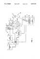
- FIG. 1shows a system for three-dimensional determination of the points on the surface of an object in accordance with the principles of the present invention
- FIG. 2shows in greater detail a block diagram for the sensor control section of the system of FIG. 1.
- FIG. 1a system 1 for determining the positions or locations of the points on the surface of an object 2 is illustrated.
- the system 1comprises a projector assembly 3 including a projector 3A for projecting electromagnetic radiation 4 at the object 2, a variable power supply 3B for supplying power to the projector and a projector power controller 3C for controlling the variable power supply.
- the electromagnetic radiation 4is assumed to be a pencil beam of optical radiation or light and the projector 3A is assumed to be a laser beam source.
- the principles of the inventionmay be also accomplished by use of a modulated continuous wave laser.
- a HeNe lasercould be gated on and off via an acousto-optic or Kerr cell or Pockels cell (with cross polarizers) modulator. These devices can provide amplitude modulation with on/off control equivalent to that of a laser source with variable power supply.
- the projected beam of radiation or light 4is incident on the object 2 and at the point of incidence 2' a spot on the surface is illuminated.
- the light creating the spotis then reflected from the surface and the reflected light 5 in the field of view of a lens 6 is collected by the lens.
- the lensthen directs or focuses the collected light 5 onto a sensor detector 7.
- the sensor detector 7comprises a plurality of independent, detector segments or elements 7-1, 7-2 . . . 7-N, each of which develops an electrical signal proportional to the power-time integral, i.e., the energy, in the part of the reflected light incident thereon. Since the resolution of the system 1 is dependent upon the number of elements in the sensor detector 7, it is desirable that the number of elements be relatively large. Available detectors meeting the requirement of a large number of elements, however, typically develop a voltage output across each element proportional to the energy or power-time integral of the incident light and typically these voltages can be read out from the elements only serially, i.e., one voltage following the other in time. Detector 7 is assumed to be such a serial type detector. A particular detector useable as the detector 7 might be the 256 element video pickup or chip sold by EG & G Reticon under component part number RL0256CEQ-011.
- the projector assembly 3, lens 6 and sensor detector 7thus together form a sensor 10 which develops electrical signals (the detector 7 signals) from which the positions of the points on the surface of the object 2 can be determined.
- the detector 7 signalselectrical signals
- an indication of the location of each illuminated point, e.g., the point 2', on the object surfacecan be obtained.
- the amplified signalsare fed to a processing unit 9.
- the latter unitusing standard triangulation practices, then analyzes and processes the signals to provide the three dimensional location of the object surface points.
- the power in the reflected light 5 incident on the detector elements 7-1 to 7-Nmust be above the power level attributable to noise and below the power level (or more precisely the power-time integral) which saturates or causes blooming (false spreading of the detected signal) at the detector elements, i.e., the power level must be within the dynamic range of the detector.
- the object surfaceis a highly reflective surface such as, for example, a solder joint on a printed circuit board
- the range of intensities of the reflected light 5 for different object surfacescan be quite broad and may be of the order of 1000:1.
- the range of 1000:1 in the expected intensities of the reflected light 5translates into a like 1000:1 dynamic range in power which must be accommodated by the detector elements 7, if the system 1 is to be able to detect the points on the various reflective surface.
- Present day detectors usable for detector 7e.g., component RL0256CEQ-011 of EG & G Reticon mentioned above, however, typically may have a nominal dynamic range of 100:1 and, in practice, a useable dynamic range of only about 6:1. Thus, conventional detectors alone are not able to satisfy the needed requirements for detection of the various object surfaces.
- this abilityis provided in the system 1, by further adapting the system to control the projector assembly 3 such that the energy of the reflected light 5 at the detector 7, over the expected dynamic range of intensities of the reflected light, is kept within the dynamic range of the sensor detector 7.
- Thisis accomplished in accord with the invention, by providing a sensor control assembly 11 which monitors the energy in parts of the reflected light 5 and inhibits the reflected light 5 from reaching the detector 7 after the energy in any one of the monitored parts exceeds a predetermined level.
- the sensor assembly 11comprises an optical beam splitter 12 which is placed in the path of the reflected light 5, between the lens 6 and the detector 7, a sensor control detector 13 and control circuitry 14.
- the transmission/reflective properties of the beam splitter 12are such that the beam splitter passes a major portion 5A of the reflected light 5 to the detector 7 undisturbed, while it reflects the smaller remaining portion 5B of the light 5 and redirects it to the sensor control detector 13.
- the detector 13is positioned relative to the beam splitter 12 so that the reflected light portion 5B is focused onto the detector 13 similarly to the light portion 5A being focused onto the detector 7.
- the detector 13also comprises a plurality of independent, detector elements 13-1 to 13-M.
- the elementsare such that the signals from the elements can be read in parallel, i.e., simultaneously with each other in real time.
- the desired real time monitoring of the energy in various parts of the reflected light 5Bi.e., those parts incident on elements 13-1 to 13-M
- These values of energyare indicative of the relative energy in the various parts of the reflected light 5A incident on the sensor detector 7.
- the energy in the parts of light 5A delivered to the sensor detector elements 7-1 to 7-Ncan be confined to the dynamic range of the sensor detector 7 over a wide range of surface reflectivities of object 2.
- the predetermined levelis adjusted such that the light 5A delivered to the elements 7-1 to 7-N result in a maximum energy in any element which is at about the middle of the dynamic range of the detector 7.
- the selection of the detector 13depends, amongst other things, on the availability of detectors whose elements can be read in parallel. Typically, as above-indicated, detectors having large numbers of elements, such as those mentioned above for the detector 7, can only be read serially and, thus are not suitable.
- the non-suitabilitystems from the fact that the light must be inhibited immediately upon reaching the desired level which can be accomplished with real time parallel readout detectors, but not with serial readout detectors that are essentially non-real for this application.
- detectors having at least 8 elements and providing output currents proportional to the incident light intensity and readable in parallelare presently available and can be used as the detector 13 with accurate results.
- a typical detector of this typeis sold under component No. PDA-20 by EG & G Photon Devices.
- FIG. 2illustrates the control circuitry 14 of the sensor control assembly 11.
- This circuitrydevelops the required power signals from the current signals of the detector elements 13-1 to 13-M and terminates the reflected light 5 to the sensor detector 7.
- the latteris accomplished by addressing the projector controller 3C which causes the power supply 3B to terminate the power to projector 3A, thereby ceasing the projection of the light 4 and, therefore, the reflected light 5.
- the output current signals from the detector elements 13-1 to 13-Mare first each integrated in respective integration circuits 22-1 to 22-M each comprised of a capacitor C and a field-effect transistor T.
- the resultant integrated signalswhich now correspond to the energy in the incident light, are then coupled to a "greatest of" circuit 23 comprised of diodes 23-1 to 23-M.
- the circuit 23forms at node 24 a value equal to the greatest value of integrated current which corresponds to the greatest energy value.
- This greatest valueis then fed to the positive input (+) of a comparator 25 and is compared to the above-mentioned predetermined value which is applied to the negative input (-) of the comparator.
- the predetermined valueis shown as a present voltage developed across a resistor R.
- a signalis generated at the comparator 25 output and the generated signal addresses the stop input of the projector power controller 3C.
- the power controller 3Cthereupon causes the projector supply 3B to cease providing power to the projector 3A and light projection ceases.
- Projected light 4 thereuponceases causing reflected light 5 (i.e., reflected light portions 5A and 5B) to also cease.
- the light power delivered to sensor detector 7is thereby stopped and thus controlled to keep within the dynamic range of the sensor detector 7 as above-described.
- the transistors T of the circuitsare turned off by the master timing control 29 of the system 1 at the start of each projection period and turned on in advance of the next projection period. This insures synchronism between the sensor control assembly 11 and the sensor 10.
- the system 1is further adapted to compensate for inherent limitations in equipment which tend to reduce the reflected intensity range sensitivity of the system and which tend to increase the operating time of the system.
- this time lagitself limits the upper end of the range of intensities of the reflected light whose resultant energy can be brought within the dynamic range of the sensor detector 7.
- the intensity of reflected lightis low, in order to bring it within the dynamic range of the sensor detector 7, the projector 1 has to be kept on for a significant amount of time. This increases the operating time of the system and, if too long, is undesirable.
- both these conditionsare alleviated, in accord with a further aspect of the invention, by adapting the system 1 such that the intensity of the projected light 4 is not constant, but varies with time over the projection period. More particularly, the intensity is increased with time over the period, starting with a low value and then increasing to a high value.
- the low initial value of intensitycompensates for the time lag in turning off the projector 3A. This is accomplished since it takes longer to saturate detector 7 at a lower power level. As a result, light reflected from highly reflective surfaces can now be more readily brought into the desired portion of the dynamic range of the sensor detector 7 by the control assembly 11. On the other hand, where the surface is not highly reflective, the increase in intensity with time significantly reduces the time needed to bring the power-time integral up into the sensor dynamic range.
- the particular manner in which the intensity of the projected light is increasedi.e., linearly, non-linearly, etc., will depend upon the system 1 parameters and operating conditions.
- the characteristiconce chosen, however, can be effected by the controller 3C controlling delivery of power from the variable power supply 3B to meet the characteristic.
- a pulsed laser with a controlled varying firing rateslow to fast
- the overall resultant effectis the same, i.e., the power of the projected light is increased with time.
- the sensor control circuitryis also provided with added circuitry for developing signals indicative of the character of the reflected light 5A being sensed by the sensor detector 7. These signals can then be used to control the projection of the light 4 by the projector 3A and/or merely to give an indication of the character of the data being developed.
- An averaging circuit 26 and a "least of" circuit 27monitor the integrated signals or energy values from the control elements 13-1 to 13-M.
- the circuit 26determines the average of the energy values, while the circuit 27 determines the lowest energy value, i.e., the so-called “base-line” energy.
- a judgement circuit 28is responsive to these values and to the highest or peak energy value from the node 24 and makes a judgement as to the quality of the data.
- the judgement circuit outputis then coupled to the controller 3C to modify the on-time of the projector 3A, accordingly.
- the judgement outputalso serves as a flag/indicator signal indicative of the quality of the data.
- the signalmight indicate that data is good or bad, or some index proportional therebetween.
- waveforms in FIG. 2show three examples of possible composite signals which might be developed by the sensor detector 7.
- Waveform Cshows "poor” quality data due to high baseline level vs. peak level.
- Waveform Bshows "poor” quality data due to high average value compared to peak value even though the baseline value is low. This high average value could be due to multiple returns as depicted in the waveform.
- waveform Ashows "good” quality data, since it is has a high value, low baseline and low average.
Landscapes
- Physics & Mathematics (AREA)
- General Physics & Mathematics (AREA)
- Length Measuring Devices By Optical Means (AREA)
Abstract
Description
Claims (44)
Priority Applications (1)
| Application Number | Priority Date | Filing Date | Title |
|---|---|---|---|
| US07/221,641US4991968A (en) | 1988-07-20 | 1988-07-20 | Three dimensional object surface determination with automatic sensor control |
Applications Claiming Priority (1)
| Application Number | Priority Date | Filing Date | Title |
|---|---|---|---|
| US07/221,641US4991968A (en) | 1988-07-20 | 1988-07-20 | Three dimensional object surface determination with automatic sensor control |
Publications (1)
| Publication Number | Publication Date |
|---|---|
| US4991968Atrue US4991968A (en) | 1991-02-12 |
Family
ID=22828673
Family Applications (1)
| Application Number | Title | Priority Date | Filing Date |
|---|---|---|---|
| US07/221,641Expired - LifetimeUS4991968A (en) | 1988-07-20 | 1988-07-20 | Three dimensional object surface determination with automatic sensor control |
Country Status (1)
| Country | Link |
|---|---|
| US (1) | US4991968A (en) |
Cited By (17)
| Publication number | Priority date | Publication date | Assignee | Title |
|---|---|---|---|---|
| US5408324A (en)* | 1992-03-19 | 1995-04-18 | Sony Corporation | Distance measuring method and apparatus that compares signals from plural photocells |
| US5654800A (en)* | 1994-05-19 | 1997-08-05 | General Scanning Inc, | Triangulation-based 3D imaging and processing method and system |
| US5691544A (en)* | 1992-06-24 | 1997-11-25 | Robotic Vision Systems, Inc. | Apparatus for obtaining three-dimensional data from multiple parts or devices in a multi-pocketed tray |
| US5793051A (en)* | 1995-06-07 | 1998-08-11 | Robotic Vision Systems, Inc. | Method for obtaining three-dimensional data from semiconductor devices in a row/column array and control of manufacturing of same with data to eliminate manufacturing errors |
| DE19738480C1 (en)* | 1997-09-03 | 1998-11-26 | Bernward Maehner | Optical measuring method for 3-dimensional object |
| US5859924A (en)* | 1996-07-12 | 1999-01-12 | Robotic Vision Systems, Inc. | Method and system for measuring object features |
| US6075883A (en)* | 1996-11-12 | 2000-06-13 | Robotic Vision Systems, Inc. | Method and system for imaging an object or pattern |
| US6486963B1 (en) | 2000-06-20 | 2002-11-26 | Ppt Vision, Inc. | Precision 3D scanner base and method for measuring manufactured parts |
| US6501554B1 (en) | 2000-06-20 | 2002-12-31 | Ppt Vision, Inc. | 3D scanner and method for measuring heights and angles of manufactured parts |
| US6509559B1 (en) | 2000-06-20 | 2003-01-21 | Ppt Vision, Inc. | Binary optical grating and method for generating a moire pattern for 3D imaging |
| US6522777B1 (en) | 1998-07-08 | 2003-02-18 | Ppt Vision, Inc. | Combined 3D- and 2D-scanning machine-vision system and method |
| US20040263834A1 (en)* | 1990-11-16 | 2004-12-30 | Applied Materials, Inc. | Optical inspection apparatus for substrate defect detection |
| US20050029168A1 (en)* | 2003-08-01 | 2005-02-10 | Jones William J. | Currency processing device, method and system |
| US20050111726A1 (en)* | 1998-07-08 | 2005-05-26 | Hackney Joshua J. | Parts manipulation and inspection system and method |
| US20050128473A1 (en)* | 1999-11-17 | 2005-06-16 | Applied Materials, Inc. | Method and apparatus for article inspection including speckle reduction |
| US7142301B2 (en) | 1999-07-08 | 2006-11-28 | Ppt Vision | Method and apparatus for adjusting illumination angle |
| US7353954B1 (en) | 1998-07-08 | 2008-04-08 | Charles A. Lemaire | Tray flipper and method for parts inspection |
Citations (3)
| Publication number | Priority date | Publication date | Assignee | Title |
|---|---|---|---|---|
| US4493533A (en)* | 1981-04-27 | 1985-01-15 | Hoffmann-La Roche Inc. | Immersion oil containing aliphatic thio compounds |
| US4634879A (en)* | 1985-03-21 | 1987-01-06 | General Electric Company | Method and system for determining surface profile information |
| US4705395A (en)* | 1984-10-03 | 1987-11-10 | Diffracto Ltd. | Triangulation data integrity |
- 1988
- 1988-07-20USUS07/221,641patent/US4991968A/ennot_activeExpired - Lifetime
Patent Citations (3)
| Publication number | Priority date | Publication date | Assignee | Title |
|---|---|---|---|---|
| US4493533A (en)* | 1981-04-27 | 1985-01-15 | Hoffmann-La Roche Inc. | Immersion oil containing aliphatic thio compounds |
| US4705395A (en)* | 1984-10-03 | 1987-11-10 | Diffracto Ltd. | Triangulation data integrity |
| US4634879A (en)* | 1985-03-21 | 1987-01-06 | General Electric Company | Method and system for determining surface profile information |
Cited By (32)
| Publication number | Priority date | Publication date | Assignee | Title |
|---|---|---|---|---|
| US20040263834A1 (en)* | 1990-11-16 | 2004-12-30 | Applied Materials, Inc. | Optical inspection apparatus for substrate defect detection |
| US5408324A (en)* | 1992-03-19 | 1995-04-18 | Sony Corporation | Distance measuring method and apparatus that compares signals from plural photocells |
| US5691544A (en)* | 1992-06-24 | 1997-11-25 | Robotic Vision Systems, Inc. | Apparatus for obtaining three-dimensional data from multiple parts or devices in a multi-pocketed tray |
| US5654800A (en)* | 1994-05-19 | 1997-08-05 | General Scanning Inc, | Triangulation-based 3D imaging and processing method and system |
| US5793051A (en)* | 1995-06-07 | 1998-08-11 | Robotic Vision Systems, Inc. | Method for obtaining three-dimensional data from semiconductor devices in a row/column array and control of manufacturing of same with data to eliminate manufacturing errors |
| US5859924A (en)* | 1996-07-12 | 1999-01-12 | Robotic Vision Systems, Inc. | Method and system for measuring object features |
| US6603874B1 (en) | 1996-11-12 | 2003-08-05 | Robotic Vision Systems, Inc. | Method and system for imaging an object or pattern |
| US6075883A (en)* | 1996-11-12 | 2000-06-13 | Robotic Vision Systems, Inc. | Method and system for imaging an object or pattern |
| US20030215127A1 (en)* | 1996-11-12 | 2003-11-20 | Howard Stern | Method and system for imaging an object or pattern |
| DE19738480C1 (en)* | 1997-09-03 | 1998-11-26 | Bernward Maehner | Optical measuring method for 3-dimensional object |
| US20090078620A1 (en)* | 1998-07-08 | 2009-03-26 | Charles A. Lemaire | Tray flipper, tray, and method for parts inspection |
| US7397550B2 (en) | 1998-07-08 | 2008-07-08 | Charles A. Lemaire | Parts manipulation and inspection system and method |
| US6603103B1 (en)* | 1998-07-08 | 2003-08-05 | Ppt Vision, Inc. | Circuit for machine-vision system |
| US8408379B2 (en) | 1998-07-08 | 2013-04-02 | Charles A. Lemaire | Parts manipulation, inspection, and replacement |
| US8286780B2 (en) | 1998-07-08 | 2012-10-16 | Charles A. Lemaire | Parts manipulation, inspection, and replacement system and method |
| US8056700B2 (en) | 1998-07-08 | 2011-11-15 | Charles A. Lemaire | Tray flipper, tray, and method for parts inspection |
| US20050111726A1 (en)* | 1998-07-08 | 2005-05-26 | Hackney Joshua J. | Parts manipulation and inspection system and method |
| US7773209B2 (en) | 1998-07-08 | 2010-08-10 | Charles A. Lemaire | Method and apparatus for parts manipulation, inspection, and replacement |
| US6956963B2 (en) | 1998-07-08 | 2005-10-18 | Ismeca Europe Semiconductor Sa | Imaging for a machine-vision system |
| US7719670B2 (en) | 1998-07-08 | 2010-05-18 | Charles A. Lemaire | Parts manipulation, inspection, and replacement system and method |
| US7353954B1 (en) | 1998-07-08 | 2008-04-08 | Charles A. Lemaire | Tray flipper and method for parts inspection |
| US6522777B1 (en) | 1998-07-08 | 2003-02-18 | Ppt Vision, Inc. | Combined 3D- and 2D-scanning machine-vision system and method |
| US20090180679A1 (en)* | 1998-07-08 | 2009-07-16 | Charles A. Lemaire | Method and apparatus for parts manipulation, inspection, and replacement |
| US20090073427A1 (en)* | 1998-07-08 | 2009-03-19 | Charles A. Lemaire | Parts manipulation, inspection, and replacement system and method |
| US7557920B2 (en) | 1999-07-08 | 2009-07-07 | Lebens Gary A | Method and apparatus for auto-adjusting illumination |
| US7142301B2 (en) | 1999-07-08 | 2006-11-28 | Ppt Vision | Method and apparatus for adjusting illumination angle |
| US7463352B2 (en) | 1999-11-17 | 2008-12-09 | Applied Materials, Inc. | Method and apparatus for article inspection including speckle reduction |
| US20050128473A1 (en)* | 1999-11-17 | 2005-06-16 | Applied Materials, Inc. | Method and apparatus for article inspection including speckle reduction |
| US6486963B1 (en) | 2000-06-20 | 2002-11-26 | Ppt Vision, Inc. | Precision 3D scanner base and method for measuring manufactured parts |
| US6501554B1 (en) | 2000-06-20 | 2002-12-31 | Ppt Vision, Inc. | 3D scanner and method for measuring heights and angles of manufactured parts |
| US6509559B1 (en) | 2000-06-20 | 2003-01-21 | Ppt Vision, Inc. | Binary optical grating and method for generating a moire pattern for 3D imaging |
| US20050029168A1 (en)* | 2003-08-01 | 2005-02-10 | Jones William J. | Currency processing device, method and system |
Similar Documents
| Publication | Publication Date | Title |
|---|---|---|
| US4991968A (en) | Three dimensional object surface determination with automatic sensor control | |
| US4634879A (en) | Method and system for determining surface profile information | |
| US4142105A (en) | Method for producing a switching signal on the passage of a contrast jump | |
| US5151608A (en) | Optical distance sensor using a laser beam and processing means | |
| US4677302A (en) | Optical system for inspecting printed circuit boards wherein a ramp filter is disposed between reflected beam and photodetector | |
| US4850712A (en) | Method and system for determining surface profile information | |
| Qian et al. | A method for measurement of multiple light spot positions on one position-sensitive detector (PSD) | |
| US4983827A (en) | Linescan apparatus for detecting salient pattern of a product | |
| US4924105A (en) | Optical measuring device with alternately-activated detection | |
| EP0512616A2 (en) | Optical scanning device | |
| US6363044B1 (en) | Automatically adapting forward or reversed biased photodiode detection circuit | |
| CA1068371A (en) | Circuit arrangements for controlling detector signals in surface inspection systems | |
| US5550800A (en) | Pick-up with adaptation | |
| US4949345A (en) | Method and apparatus for reducing the effect of random polarization on the power/energy output of lasers | |
| EP0347202A3 (en) | Excitation system for a semiconductor laser device | |
| JPS6114506A (en) | Optical sensor | |
| US5377282A (en) | Optical inspection system utilizing dynamic analog-to-digital thresholding | |
| US20040145992A1 (en) | Method and electronic circuit for controlling of a supply voltage of a laser diode | |
| JP2743038B2 (en) | Underwater distance measuring device using laser light | |
| US5134438A (en) | Image forming apparatus having a device for measuring an original density | |
| JPH0378608A (en) | Processing device of signal of optical road-surface state sensor | |
| JPH0434503Y2 (en) | ||
| JPS575187A (en) | Recorder | |
| JPS6183904A (en) | End point detection | |
| JPS5915089Y2 (en) | Laser output monitoring device |
Legal Events
| Date | Code | Title | Description |
|---|---|---|---|
| AS | Assignment | Owner name:ROBOTIC VISION SYSTEMS, INC., 425 RABRO DRIVE EAST Free format text:ASSIGNMENT OF ASSIGNORS INTEREST.;ASSIGNORS:YONESCU, WILLIAM E.;STERN, HOWARD K.;REEL/FRAME:004936/0324 Effective date:19880711 | |
| STCF | Information on status: patent grant | Free format text:PATENTED CASE | |
| FEPP | Fee payment procedure | Free format text:PAYOR NUMBER ASSIGNED (ORIGINAL EVENT CODE: ASPN); ENTITY STATUS OF PATENT OWNER: LARGE ENTITY | |
| FEPP | Fee payment procedure | Free format text:PAT HLDR NO LONGER CLAIMS SMALL ENT STAT AS SMALL BUSINESS (ORIGINAL EVENT CODE: LSM2); ENTITY STATUS OF PATENT OWNER: LARGE ENTITY | |
| CC | Certificate of correction | ||
| FPAY | Fee payment | Year of fee payment:4 | |
| AS | Assignment | Owner name:BANK OF NEW YORK, THE, NEW YORK Free format text:GRANT OF SECURITY INTEREST (PATENTS);ASSIGNOR:ROBOTIC VISION SYSTEMS, INC.;REEL/FRAME:009114/0385 Effective date:19980318 | |
| FPAY | Fee payment | Year of fee payment:8 | |
| AS | Assignment | Owner name:ROBOTIC VISION SYSTEMS, INC., NEW YORK Free format text:RELEASE OF SECURITY INTEREST;ASSIGNOR:THE BANK OF NEW YORK;REEL/FRAME:010731/0869 Effective date:20000329 | |
| AS | Assignment | Owner name:PNC BANK, NATIONAL ASSOCIATION, NEW JERSEY Free format text:SECURITY INTEREST;ASSIGNOR:ROBOTIC VISION SYSTEMS, INC.;REEL/FRAME:010804/0380 Effective date:20000428 | |
| FPAY | Fee payment | Year of fee payment:12 | |
| REMI | Maintenance fee reminder mailed | ||
| AS | Assignment | Owner name:RVSI INSPECTION LLC, NEW YORK Free format text:NUNC PRO TUNC ASSIGNMENT;ASSIGNOR:ROBOTIC VISION SYSTEMS, INC., NOW KNOWN AS ACUITY CIMATRIX, INC.;REEL/FRAME:018279/0776 Effective date:20060721 | |
| AS | Assignment | Owner name:RVSI ACQUISITIONS, LLC, NEW YORK Free format text:RELEASE OF LIENS, CLAIMS ENCUMBRANCES BY COURT;ASSIGNOR:UNITED STATES BANKRUPTCY COURT, DISTRICT OF NEW HAMPSHIRE, CASE 04-14151, JUDGE J. MICHAEL DEASY, DOCUMENT NO. 819;REEL/FRAME:020462/0087 Effective date:20050311 Owner name:RVSI INSPECTION LLC, NEW YORK Free format text:RELEASE OF LIENS, CLAIMS ENCUMBRANCES BY COURT;ASSIGNOR:UNITED STATES BANKRUPTCY COURT, DISTRICT OF NEW HAMPSHIRE, CASE 04-14151, JUDGE J. MICHAEL DEASY, DOCUMENT NO. 819;REEL/FRAME:020462/0087 Effective date:20050311 | |
| AS | Assignment | Owner name:RUDOLPH TECHNOLOGIES, INC., NEW JERSEY Free format text:ASSIGNMENT OF ASSIGNORS INTEREST;ASSIGNOR:RVSI INSPECTION, LLC;REEL/FRAME:021669/0907 Effective date:20080122 |