US4990838A - Movement trajectory generating method of a dynamical system - Google Patents
Movement trajectory generating method of a dynamical systemDownload PDFInfo
- Publication number
- US4990838A US4990838AUS07/462,531US46253190AUS4990838AUS 4990838 AUS4990838 AUS 4990838AUS 46253190 AUS46253190 AUS 46253190AUS 4990838 AUS4990838 AUS 4990838A
- Authority
- US
- United States
- Prior art keywords
- trajectory
- movement
- time
- generating
- controlled object
- Prior art date
- Legal status (The legal status is an assumption and is not a legal conclusion. Google has not performed a legal analysis and makes no representation as to the accuracy of the status listed.)
- Expired - Lifetime
Links
Images


Classifications
- G—PHYSICS
- G05—CONTROLLING; REGULATING
- G05B—CONTROL OR REGULATING SYSTEMS IN GENERAL; FUNCTIONAL ELEMENTS OF SUCH SYSTEMS; MONITORING OR TESTING ARRANGEMENTS FOR SUCH SYSTEMS OR ELEMENTS
- G05B19/00—Programme-control systems
- G05B19/02—Programme-control systems electric
- G05B19/18—Numerical control [NC], i.e. automatically operating machines, in particular machine tools, e.g. in a manufacturing environment, so as to execute positioning, movement or co-ordinated operations by means of programme data in numerical form
- G05B19/41—Numerical control [NC], i.e. automatically operating machines, in particular machine tools, e.g. in a manufacturing environment, so as to execute positioning, movement or co-ordinated operations by means of programme data in numerical form characterised by interpolation, e.g. the computation of intermediate points between programmed end points to define the path to be followed and the rate of travel along that path
- B—PERFORMING OPERATIONS; TRANSPORTING
- B25—HAND TOOLS; PORTABLE POWER-DRIVEN TOOLS; MANIPULATORS
- B25J—MANIPULATORS; CHAMBERS PROVIDED WITH MANIPULATION DEVICES
- B25J9/00—Programme-controlled manipulators
- B25J9/16—Programme controls
- B25J9/1602—Programme controls characterised by the control system, structure, architecture
- B25J9/161—Hardware, e.g. neural networks, fuzzy logic, interfaces, processor
- G—PHYSICS
- G06—COMPUTING OR CALCULATING; COUNTING
- G06N—COMPUTING ARRANGEMENTS BASED ON SPECIFIC COMPUTATIONAL MODELS
- G06N3/00—Computing arrangements based on biological models
- G06N3/02—Neural networks
- G06N3/04—Architecture, e.g. interconnection topology
- G06N3/045—Combinations of networks
- G—PHYSICS
- G06—COMPUTING OR CALCULATING; COUNTING
- G06N—COMPUTING ARRANGEMENTS BASED ON SPECIFIC COMPUTATIONAL MODELS
- G06N3/00—Computing arrangements based on biological models
- G06N3/02—Neural networks
- G06N3/04—Architecture, e.g. interconnection topology
- G06N3/0499—Feedforward networks
- G—PHYSICS
- G06—COMPUTING OR CALCULATING; COUNTING
- G06N—COMPUTING ARRANGEMENTS BASED ON SPECIFIC COMPUTATIONAL MODELS
- G06N3/00—Computing arrangements based on biological models
- G06N3/02—Neural networks
- G06N3/08—Learning methods
- G06N3/09—Supervised learning
- G—PHYSICS
- G05—CONTROLLING; REGULATING
- G05B—CONTROL OR REGULATING SYSTEMS IN GENERAL; FUNCTIONAL ELEMENTS OF SUCH SYSTEMS; MONITORING OR TESTING ARRANGEMENTS FOR SUCH SYSTEMS OR ELEMENTS
- G05B2219/00—Program-control systems
- G05B2219/30—Nc systems
- G05B2219/33—Director till display
- G05B2219/33027—Artificial neural network controller
- G—PHYSICS
- G05—CONTROLLING; REGULATING
- G05B—CONTROL OR REGULATING SYSTEMS IN GENERAL; FUNCTIONAL ELEMENTS OF SUCH SYSTEMS; MONITORING OR TESTING ARRANGEMENTS FOR SUCH SYSTEMS OR ELEMENTS
- G05B2219/00—Program-control systems
- G05B2219/30—Nc systems
- G05B2219/42—Servomotor, servo controller kind till VSS
- G05B2219/42155—Model
- G—PHYSICS
- G05—CONTROLLING; REGULATING
- G05B—CONTROL OR REGULATING SYSTEMS IN GENERAL; FUNCTIONAL ELEMENTS OF SUCH SYSTEMS; MONITORING OR TESTING ARRANGEMENTS FOR SUCH SYSTEMS OR ELEMENTS
- G05B2219/00—Program-control systems
- G05B2219/30—Nc systems
- G05B2219/49—Nc machine tool, till multiple
- G05B2219/49157—Limitation, collision, interference, forbidden zones, avoid obstacles
Definitions
- the present inventionrelates to a movement trajectory generating method of a dynamical system. More specifically, the present invention relates to a movement trajectory generating method of a dynamical system, which is capable of automatically generating, by least dissipation of energy, an objective trajectory of a dynamical system having nonlinear characteristics such as robots, power generation plants, motor engines, elevators, trains, cars and other vehicles, and which makes it possible to speech synthesis or to recognize continuous speech.
- the calculation timeis exponentially increased when the degrees of freedom of the controlled object and the number of obstacles are increased, and therefore such methods are not practical.
- the dynamics of the controlled objectis not taken into account in such methods, smooth movement cannot be obtained and excessive load is applied to the controlled object.
- a principal object of the present inventionis to provide a movement trajectory generating method of a dynamical system, which does not require strict modeling of a nonlinear controlled object and which is capable of automatically generating a smooth trajectory as in movement of human hands without increasing calculation time exponentially even if the number of degrees of freedom of the controlled object or the number of obstacles is increased.
- the present inventionuses not only various conditions for estimating a movement trajectory, such as the movement time, the start point, the end point, the via-point of the trajectory, or obstacles to the movement, but also uses a criterion for ensuring smoothness the movement trajectory by minimizing functions of evaluation in integration for the movement time equivalent to the square of a jerk, integration for the movement time equivalent to the square of rate of change of torque, and integration for the movement time equivalent to the square of rate of change of force, whereby the movement trajectory is formed.
- trajectory running and forming systemshave improvements in performance, in which the calculation time increases only in a linear order of degrees of freedom of a control object, a trajectory is generated with high precision and in a wide range of applications, strict modeling of the controlled object or estimations of parameters are not required, and the automatic formation of the trajectory is smooth as in movements of a human, causing no excessive load to the controlled object.
- a movement trajectoryis formed by a large number of cascade connections of internal models each obtained by multiplying, by a unit of time, a vector field of a nonlinear differential equation describing dynamical characteristics of a controlled object, and by using a bypass corresponding to a flow of the differential equations and discrete diffusion couplings for satisfying the criterion of evaluation of movement smoothness.
- a movement trajectoryis formed by an ultra multilayer neural network including a large number of cascade connections of multilayer neural networks in which internal models obtained by multiplying vector fields of nonlinear differential equations by a unit of time are learned in the multilayer neural networks, and further including bypasses corresponding to a flow of the differential equations and electric synapses for satisfying the criterion of evaluation of movement smoothness.
- FIG. 1is a block diagram showing learning in an embodiment of the present invention.
- FIG. 2is a block diagram in which a trajectory is being generated according to the embodiment of the invention.
- FIG. 3is a diagram for explaining a 2-link robot manipulator used for testing the embodiment of the invention in computer simulation experiments.
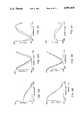
- FIGS. 4 and 5show circuit simulation results in relaxation calculation with respect to trajectory generation by using a neural network model. Particularly, FIG. 4 shows the initial condition of the neural network model, and FIG. 5 shows the stable equilibrium state of the network after 1,000 iterations and the corresponding realized trajectory by the model manipulator.
- FIG. 6is a bird's eye view of a hand path between the start point (0.3, 0.3) and the end point (0.15, 0.15).
- FIG. 7is a diagram showing results of simulation of trajectory generation by a network model while avoiding obstacles.
- FIG. 8is a diagram showing corresponding trajectories and torque waveforms.
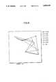
- FIG. 9is a bird's eye view of a hand path avoiding two obstacles.
- FIG. 10is a diagram showing hand paths and arm configurations for a via-point movement.
- FIG. 11shows diagrams showing trajectories and torque waveforms.
- FIGS. 1 and 2are block diagrams showing a model according to a method of an embodiment of the present invention. Particularly, FIG. 1 shows a block diagram of learning and FIG. 2 shows a block diagram of trajectory formation.
- the cascade structure of the neural network model shown in FIG. 1is simply a direct hardware implementation of Euler's method above.
- FIG. 1For simplicity, a single degree of freedom case without the kinematics problem is shown. All four-layer network units are identical. Operations of the model are divided into the learning phase shown in FIG. 1, and the pattern generating phase shown in FIG. 2. In the learning phase, the network unit learns the vector field of the dynamical equation which describes the forward dynamics of the controlled object 4 such as a manipulator. In the pattern generating phase, the network relaxes its state to minimum energy equilibrium based on backward propagation of errors through the acquired forward model.
- the modelincludes many identical four-layer network units 1, 2, 3.
- the jth network unitcorresponds to time j ⁇ t.
- the network units 1, 2, 3are connected in a cascade formation. Operation of each neuron is assumed to be the linear weighted summation of synaptic inputs and the sigmoid nonlinear transformation.
- the input-output transformation of the neurons in the first and fourth layersis assumed linear.
- Let u m ,j i and y m ,j idenote an average membrane potential (i.e. weighted summation of all synaptic inputs) and an output (i.e. average firing frequency) of the ith neuron in the mth layer of the jth network unit.
- ⁇is the input-output transformation.
- w k ,i m-1 ,mdenotes a synaptic weight from the kth neuron in the m-1th layer to the ith neuron in the mth layer. Then the following equations hold:
- the cascade structureis formed by a unit-weight serial connection from the fourth layer of the jth network unit to the first layer of the j+1th network unit, and a unit-weight connection bypass from the fourth layer of the jth network unit to the fourth layer of the j+1th network unit:
- serial connectionscorrespond to the second terms of the right sides of Euler's formula.
- bypass connectionscorrespond to the first terms of the right sides, and just convey the previous states to the next time step.
- equation (8)corresponds to the equations (3) and (4). Since the vector field is time invariant, all the network units are identical. That is, the number of neurons and the synaptic weights are exactly the same for all units.
- the network unitconsists of four layers of neurons.
- the first layer 11, 21, 31represents the time course of the trajectory and the torque.
- the third layer 13, 23, 33represents the change of the trajectory within a unit of time, that is, the vector field multiplied by the unit of time, ⁇ t ⁇ h( ⁇ (j ⁇ t), ⁇ (j ⁇ t), ⁇ (j ⁇ t)).
- the second layer 12, 22, 32provides the necessary nonlinear transformations for learning the vector filed multiplied by the unit of time.
- the fourth layer 14, 24, 34 and the output line on the right siderepresent the estimated time course of the trajectory.
- the fourth layer neurons in the jth unitoutput the estimated trajectory, ⁇ (j ⁇ t) and ⁇ (j ⁇ t) at time j ⁇ t, which are the summation of their synaptic inputs, i.e., the outputs of the third layer in the jth unit and outputs from the fourth layer neurons in the (j-1)st unit (see the equation (8)).
- the first two neurons in the first layer of the first unitrepresent the initial conditions ⁇ (0) and ⁇ (0). Because the model faithfully reproduces the time structure of the dynamical system, intrinsic properties of the flow of the dynamical system, to be described below, are embedded into the cascade structure of the model.
- the neural network model shown in FIG. 1those properties of the flow of the dynamical system are embedded into the structure.
- the common input torqueare fed to both the controlled object 4 and the neural network model.
- the realized trajectory ( ⁇ , ⁇ ) from the controlled object 4is used as a teaching signal to acquire the forward dynamics model between the first and third layers 11, 21, 31 and 13, 23, 33 of the network unit.
- the steepest descent methodis introduced for learning synaptic rates in the network unit, with the following error function E for the output of the fourth layer 14, 24, 34, ##EQU2## where c represents the input torque and the resulting trajectory.
- the back-propagation learning algorithm(Rumelhart, Hinton, & Williams, 1986; Werbos, 1988) can be applied to this case as follows.
- the error signal of neurons in the third layer 13, 23, 33is the same as that of the 4th layer 14, 24, 34.
- the error signals of neurons in the 1st and 2nd layers 11, 21, 31 and 22, 22, 32are computed from those in the 3rd layer as in the usual back-propagation learning rule: ##EQU4##
- the error signals for all neuronsare calculated from the equation (10) exactly the same as in the learning phase, while replacing the realized trajectory as the teaching signal by the desired end point, the via-point, obstacles and so on, as the objective signal. If we consider the simple case without via-point or obstacles, the backward propagation of errors in the pattern generating phase obeys the following equation:
- ⁇ d ,N( ⁇ d ,N, ⁇ d ,N) represents desired terminal conditions.
- the error signalsare not used for synaptic modification.
- the error signals to the torque neurons in the first layer 11, 21, 31are used for dynamical state change of the model. That is, the network changes its state autonomously by forward synaptic calculation and by back-propagation of error signals through the cascade structure while obeying the following differential equation.
- the Ljapunov functionin a simple case without the via-point or the obstacle avoidance conditions.
- the first two terms of the Ljapunov functionrequire that the hand reaches the end point with a specific speed and the third term guarantees the minimum torque change criterion.
- the stable equilibrium point of the network dynamicscorresponds to the minimum-energy state, and, hence, the network outputs the torque, which realizes the minimum torque trajectory.
- An appropriate delay lineshould be inserted between the cascade network and the controlled object in FIG. 2.
- the conductance gis slowly decreased to 0, during relaxation of the state point to the equilibrium, similar to the temperature in "simulated annealing" (Kirkpatrick, Gellat, Vecci, 1983).
- the first two terms of the Ljapunov functionare the hard constraints imposed by trajectory specification, and the third term is the smoothness constraint. Introduction of the third energy as electrical couplings resolves the ill-posed trajectory formation. The network learns the first two terms of the energy as synaptic weights, and then minimizes the total energy.
- the relaxation computation of the cascade networkhas a close relationship with the first-order gradient method which is a well known numerical method in optimal control theory (Bryson and Ho, 1975).
- the forward calculation through the cascade structure using the equations (3) and (4)is interpreted as forward numerical integration of a control system equations.
- the backward propagation of erroris interpreted as backward integration of a part of an adjoint equation of the dynamics equation.
- the equation (12)can be interpreted as backward Euler's numerical integration of a part of the adjoint equation.
- the proposed networkis different from the control theory approach in that it does not utilize any co-state (in this case ⁇ ).
- the neural network modeluses fewer state variables, (iii) and it is several times faster.
- the most marked advantage of the neural network modelis that we can impose constraints on the motor command by directly constraining states of the neurons which represent the motor command. Instead, if we use the co-state, these constraints must be treated as those on the state variables, which leads to further complication of the calculations. This is important, since when we extend the minimum torque-change model to the minimum muscle tension-change model, we must introduce positivity constraints on muscle tensions. Actually, in this case, if we use a standard sigmoid input-output transformation function for neurons representing motor commands, we do not need to introduce any extra constraint for positivity of muscle tension at all.
- FIG. 3is a diagram showing a two-joint robotic manipulator within a horizontal plane as a model of a human arm.
- FIGS. 1 and 2The performance of the network model proposed in FIGS. 1 and 2 was examined in computer simulation experiments of trajectory formation.
- a two-link robotic manipulator shown in FIG. 3was used as model of a human right arm.
- Links 21 and 22correspond to the upper arm and the forearm, and joints 31 and 32 correspond to the shoulder and the elbow.
- the joint 31 (shoulder)is located at the origin of the X-Y cartesian coordinates.
- the positive direction of the X coordinateis the right side direction of the body, and the positive direction of the Y coordinate is the front direction of the body.
- Physical parameters of the model manipulatorare shown in Table 1. They were chosen based on experiment data and human arm geometry (see Uno et al, 1989).
- the hand positionis represented as (X, Y) in meter.
- the manipulatorhas two degrees of freedom within the plane, there is no redundancy at the kinematics level. Because the manipulator has only one actuator at each joint, there is no redundancy at the dynamics level. Consequently, in this simplest case, the forward kinematics and dynamics of the manipulator can be described by the following ordinary differential equations expressed in task-oriented coordinates.
- ⁇ 1 (t) and ⁇ 2 (t)represent torque waveforms fed to the shoulder and the elbow.
- p and qare nonlinear functions which determine the nonlinear dynamics and kinematics of the manipulator.
- the simple cascade neural network model shown in FIG. 1is a composite model of the forward dynamics and kinematics of the controlled object and conducted simulation with the following conditions.
- the right side of the equation (15)is acquired in a three-layer network unit.
- the first layer of each network unitcontains 6 neurons. 4 of them represent the task space trajectory X, Y, X, Y, and the other 2 represent torque waveforms ⁇ 1 , ⁇ 2.
- the third layer of each network unitcontains 4 neurons which represent changes of the task space trajectory within a unit of time (i.e. the right sides of the equation (15) multiplied by ⁇ t).
- the fourth layer of each network unitcontains 4 neurons, and they represent the task space trajectory X, Y, X, Y.
- the movement timewas set at 500 ms. 5 ms was chosen for the time step ⁇ t of the network.
- the total neural network modelcontains 3,400 neurons and 20,000 modifiable synaptic weights. However, only 200 synaptic weights are independent parameters to be acquired since each network unit is identical.
- the first schemeuses back-propagation of trajectory errors all through the cascade structure.
- the second schemeis simpler than this.
- the jth network unitreceives the realized trajectory and the motor command at (j-1) ⁇ t as inputs, and receives the realized trajectory at j ⁇ t as a desired output or the teaching signal. Consequently, each network unit is trained to acquire only the vector field multiplied by ⁇ t, and no back-propagation of trajectory errors is conducted.
- trajectory formation between two pointswas examined.
- the objectiveis to move the arm between the starting point (0.1, 0.2) and the end point of (0.2, 0.3) in 500 ms based on the minimum torque-change criterion.
- FIGS. 4 and 5show relaxation of the neural network state during generation of a movement between two points.
- FIG. 4shows the initial condition of the neural network model
- FIG. 5shows the stable equilibrium state of the network after 1,000 iterations and the corresponding realized trajectory by the model manipulator.
- the abscissa of all the figuresshow the time in seconds.
- the left columnshows the hand position trajectory X(t) (above) and Y(t) (below).
- the scale of the ordinateis in meters.
- the middle columnshows the hand velocity history X(t) (above) and Y(t) (below).
- the scale of the ordinateis in meters per second.
- the right columnshows the torque waveforms fed to the shoulder (above) and to the elbow (below).
- Two-point chain curvesare exact trajectories and torque waveforms of the minimum torque-change model calculated by a Newton-like method.
- One-point chain curves in the left and middle columnsare trajectories estimated by the network model.
- Solid curves in the right columnrepresent torque waveforms generated by the network model.
- Solid curves in the left and middle columns in FIG. 5show the realized trajectory by the model manipulator when the generated torque is fed to it.
- the states of 200 torque neuronswere set at random initial values at the beginning of relaxation. After 1,000 iterations of relaxation computation according to the equation (13), the state settles down to a stable equilibrium and generates an estimated trajectory and a torque shown in FIG. 5.
- Solid curves in FIG. 5show a trajectory realized by the model manipulator when fed the torque estimated by the network. The estimated trajectory reaches the end point at the given time and stopped properly. The generated torque waveforms were smooth enough and fairly close to the exact solution.
- the realized trajectorydid not reach the end point. There are consistent errors between the minimum torque-change trajectory (two-point chain curve), the estimated trajectory (one-point chain curve) and the realized trajectory (solid curve). We know that the cause of this error is incomplete running of dynamics and kinematics, since the error is almost negligible in the simulation experiments where an accurate forward model is used. Thus, we expect that the network can generate a more accurate trajectory and torque if we use more efficient running algorithms such as the conjugate gradient method or the quasi-Newton method instead of the back-propagation (steepest descent) algorithm, and if we carefully select more independent training data.
- more efficient running algorithmssuch as the conjugate gradient method or the quasi-Newton method instead of the back-propagation (steepest descent) algorithm, and if we carefully select more independent training data.
- FIG. 6is a bird's-eye view of a hand path between two points and 5 configurations of the model manipulator every 125 ms.
- the scale in the figureis 0.1 m.
- the solid curveis the realized hand path, and the two-point chain curve is the exact minimum torque-change hand path calculated by a Newton-like method.
- the number of relaxation computation iterationswas 1,000.
- the minimum torque-change hand path and the realized hand pathare shown by the two-point chain curve and the solid curve, respectively.
- the minimum-torque change hand path and the one estimated by the neural network modelcannot be separately seen.
- the error between the realized hand path and the minimum torque-change hand pathwas due to the incomplete running of the forward model.
- FIG. 8shows trajectories and torque waveforms corresponding to FIG. 7.
- the two-point chain curves in FIGS. 7 and 8show hand paths, trajectories and torque waveforms for the minimum torque-change trajectory without the obstacle.
- the number of relaxation computation iterationswas 2,000 in this experiment.
- the corresponding obstacle avoidance error signals for the first and the second neurons in the fourth layer of the jth network unitcan be calculated as follows: ##EQU7##
- the sign of the error signalis opposite that of the usual error signals associated with the desired end or via-points, since h is positive.
- the center of the obstacleacts like a repelling point when the hand position is within a circle. If the hand is located outside the obstacle, the obstacle does not exert any force on the arm at all.
- FIG. 9is a bird's-eye view of a hand path which avoids two obstacles.
- a two-point chain curveshows the exact minimum torque-change hand path calculated by a Newton-like method when there is no obstacle
- the starting pointis (0.1, 0.2), and the end point is (0.2, 0.3). Centers of the two circle obstacles with a radius 0.02 m are (0.125, 0.245) and (0.175, 0.255).
- a one-point chain curveshows a hand path estimated by the network model.
- a solid curveshows a realized trajectory by the manipulator when the generated torque is fed to it. Because we used an accurate model of the forward dynamics in this simulation, these two curves almost coincided and cannot be seen separately at this solution. The number of relaxation computation iterations was 10,000 in this experiment.
- the neural network modelhas multiple stable equilibrium in relaxation computation for avoidance of multiple obstacles.
- the networksettled down to three different trajectories. The first is shown in FIG. 9.
- the second trajectoryruns above the two obstacles, and the third one runs below.
- the forward dynamics and kinematics of the armis nonlinear.
- the obstacle avoidance potential fieldis not convex. Consequently, the total energy of the network is not convex, and the steepest descent method employed in this paper may be trapped to local minimum, as exemplified in this example.
- we can avoid local minimumby adding noise to the relaxation equation as in the simulated annealing. However, we do not think this is necessary.
- FIG. 10shows hand path and arm configuration for a via-point movement
- FIG. 10shows trajectories and torque waveforms for the via-point movement
- FIG. 10is the same format as FIG. 6.
- FIG. 11is the same format as FIG. 5.
- the parallelogram in FIG. 10shows the location of the via-point.
- Parallelograms in the left column of FIG. 11show the corresponding X and Y coordinates of the via-point.
- the number of relaxation computation iterationswas 5,000 in this experiment.
- the neural networkgenerated a via-point trajectory which passes through the via-point (0, 0.23) from the start point (-0.2, 0.3) to the end point (0.2, 0.3).
- the neural network modelautonomously finds the best time to pass the via-point on the minimum torque change criterian using the energy equationor.
- the estimated and realized trajectorieswere in fairly close agreement with the trajectory calculated by the Newton-like method. In particular, between these two methods, the time required to pass the via-point differed by only 0.005 s.
- the modelis provided with the cascade connection structure for the learning of each unit layer circuit and the flow of the differential equations, and the electronic synapses for ensuring smoothness of movement and bypasses.
- the computation timeincreases only in linear order of degrees of freedom of the controlled object.
- the method according to the embodiment of the inventionmakes it possible to automatically generate a trajectory with high precision and to control objects in a wide range of applications.
- trajectory learning and generating systemsin general have improvements in performance that a trajectory can be automatically generated smoothly as in movement of a human without causing any excessive load to the controlled object.
Landscapes
- Engineering & Computer Science (AREA)
- Physics & Mathematics (AREA)
- Theoretical Computer Science (AREA)
- Computing Systems (AREA)
- Automation & Control Theory (AREA)
- Artificial Intelligence (AREA)
- Software Systems (AREA)
- Mathematical Physics (AREA)
- General Physics & Mathematics (AREA)
- Evolutionary Computation (AREA)
- Biophysics (AREA)
- Molecular Biology (AREA)
- General Health & Medical Sciences (AREA)
- General Engineering & Computer Science (AREA)
- Data Mining & Analysis (AREA)
- Computational Linguistics (AREA)
- Biomedical Technology (AREA)
- Life Sciences & Earth Sciences (AREA)
- Health & Medical Sciences (AREA)
- Manufacturing & Machinery (AREA)
- Human Computer Interaction (AREA)
- Fuzzy Systems (AREA)
- Robotics (AREA)
- Mechanical Engineering (AREA)
- Feedback Control In General (AREA)
- Manipulator (AREA)
- Testing Or Calibration Of Command Recording Devices (AREA)
Abstract
Description
dθ/dt=θ (1)
dθ/dt=h(θ, θ, τ), (2)
θ ((j+1)Δt)=θ(jΔt)+Δt·θ(jΔt) (3)
θ ((j+1)Δt)=θ(jΔt)+Δt·h(θ(jΔt),θ(jΔt),τ(jΔt)). (4)
y.sub.1,j+1.sup.i =y.sub.4,j,.sup.i (7)
y.sub.4,j+1.sup.i =y.sub.4,j.sup.i +y.sub.3,j+1.sup.i. (8)
j=1, 2 . . . , N-1; i=1,2 (12)
T·dr.sub.j /ds=δ.sub.1,j.sup.3 +g(τ.sub.j+1 -2τ.sub.j +τ.sub.j-1) j=0, 1, 2, . . . , N-1 (13)
TABLE 1 ______________________________________ Parameter Upper arm Forearm ______________________________________ L.sub.k (m) 0.25 0.35 S.sub.k (m) 0.11 0.15 M.sub.k (kg) 0.9 1.1 I.sub.k (kgm.sup.2) 0.065 0.100 - B.sub.k (kgm.sup.2 /s) 0.07 0.07 ______________________________________
dX/dt=X
dY/dt=Y
dX/dt=p (X, Y, X, Y, τ.sup.1, τ.sup.2)
dY/dt=q (X, Y, X, Y, τ.sup.1, τ.sup.2) (15)
Claims (12)
Applications Claiming Priority (2)
| Application Number | Priority Date | Filing Date | Title |
|---|---|---|---|
| JP64000768AJP2676397B2 (en) | 1989-01-05 | 1989-01-05 | Dynamic trajectory generation method for dynamic system |
| JP64-768 | 1989-01-05 |
Publications (1)
| Publication Number | Publication Date |
|---|---|
| US4990838Atrue US4990838A (en) | 1991-02-05 |
Family
ID=11482876
Family Applications (1)
| Application Number | Title | Priority Date | Filing Date |
|---|---|---|---|
| US07/462,531Expired - LifetimeUS4990838A (en) | 1989-01-05 | 1990-01-03 | Movement trajectory generating method of a dynamical system |
Country Status (4)
| Country | Link |
|---|---|
| US (1) | US4990838A (en) |
| EP (1) | EP0377467B1 (en) |
| JP (1) | JP2676397B2 (en) |
| DE (1) | DE69030592T2 (en) |
Cited By (86)
| Publication number | Priority date | Publication date | Assignee | Title |
|---|---|---|---|---|
| US5167006A (en)* | 1989-12-29 | 1992-11-24 | Ricoh Company, Ltd. | Neuron unit, neural network and signal processing method |
| US5172253A (en)* | 1990-06-21 | 1992-12-15 | Inernational Business Machines Corporation | Neural network model for reaching a goal state |
| WO1993012475A1 (en)* | 1991-12-09 | 1993-06-24 | Siemens Aktiengesellschaft | Process for optimising control parameters for a system having an actual behaviour depending on the control parameters |
| US5311421A (en)* | 1989-12-08 | 1994-05-10 | Hitachi, Ltd. | Process control method and system for performing control of a controlled system by use of a neural network |
| US5331121A (en)* | 1990-03-28 | 1994-07-19 | Mitsubishi Denki Kabushiki Kaisha | Elevator control apparatus |
| US5371834A (en)* | 1992-08-28 | 1994-12-06 | The United States Of America As Represented By The Administrator Of The National Aeronautics And Space Administration | Adaptive neuron model--an architecture for the rapid learning of nonlinear topological transformations |
| US5377307A (en)* | 1992-10-07 | 1994-12-27 | Schlumberger Technology Corporation | System and method of global optimization using artificial neural networks |
| US5384895A (en)* | 1992-08-28 | 1995-01-24 | The United States Of America As Represented By The Secretary Of The Navy | Self-organizing neural network for classifying pattern signatures with `a posteriori` conditional class probability |
| US5396415A (en)* | 1992-01-31 | 1995-03-07 | Honeywell Inc. | Neruo-pid controller |
| US5404423A (en)* | 1992-06-16 | 1995-04-04 | Nippon Telegraph And Telephone Corporation | Method and apparatus for indetification, forecast, and control of a non-linear flow on a physical system network using a neural network |
| US5412163A (en)* | 1990-05-29 | 1995-05-02 | Mitsubishi Denki Kabushiki Kaisha | Elevator control apparatus |
| US5412754A (en)* | 1992-06-30 | 1995-05-02 | At&T Corp. | Reverse time delay neural network for pattern generation |
| US5426722A (en)* | 1993-09-09 | 1995-06-20 | Stratasys, Inc. | Method for optimizing the motion of a multi-axis robot |
| US5428559A (en)* | 1991-08-14 | 1995-06-27 | Kabushiki Kaisha Toshiba | Predictive control method and apparatus |
| US5428710A (en)* | 1992-06-29 | 1995-06-27 | The United States Of America As Represented By The Administrator Of The National Aeronautics And Space Administration | Fast temporal neural learning using teacher forcing |
| US5438647A (en)* | 1987-03-12 | 1995-08-01 | Toyota Jidosha Kabushiki Kaisha | Multi-manipulator robot apparatus |
| US5485546A (en)* | 1990-04-27 | 1996-01-16 | Neurosciences Research Foundation, Inc. | Discrimination and testing methods and apparatus employing adaptively changing network behavior based on spatial and heterocellular modification rules |
| US5485545A (en)* | 1991-06-20 | 1996-01-16 | Mitsubishi Denki Kabushiki Kaisha | Control method using neural networks and a voltage/reactive-power controller for a power system using the control method |
| US5495158A (en)* | 1994-09-30 | 1996-02-27 | Allen-Bradley Company, Inc. | Apparatus and method used with AC motors for controlling motor operation |
| US5504841A (en)* | 1990-11-06 | 1996-04-02 | Sony Corporation | Method of processing signals within a neural network to position arobot |
| US5513097A (en)* | 1993-05-17 | 1996-04-30 | Siemens Aktiengesellschaft | Method and control device for controlling a process including the use of a neural network having variable network parameters |
| US5529147A (en)* | 1990-06-19 | 1996-06-25 | Mitsubishi Denki Kabushiki Kaisha | Apparatus for controlling elevator cars based on car delay |
| US5555347A (en)* | 1992-09-21 | 1996-09-10 | Toyoda Koki Kabushiki Kaisha | Method and apparatus for controlling a robot using a neural network |
| US5566275A (en)* | 1991-08-14 | 1996-10-15 | Kabushiki Kaisha Toshiba | Control method and apparatus using two neural networks |
| US5579442A (en)* | 1993-04-30 | 1996-11-26 | Fujitsu Limited | Adaptive kinematic control apparatus |
| US5581662A (en)* | 1989-12-29 | 1996-12-03 | Ricoh Company, Ltd. | Signal processing apparatus including plural aggregates |
| US5586223A (en)* | 1992-10-27 | 1996-12-17 | Eastman Kodak Company | High speed segmented neural network and fabrication method |
| US5594644A (en)* | 1992-05-22 | 1997-01-14 | Honda Giken Kogyo Kabushiki Kaisha | Method and system for generating trajectory of robot and the like |
| US5608842A (en)* | 1993-11-11 | 1997-03-04 | Siemens Aktiengesellschaft | Method and device for conducting a process in a controlled system with at least one precomputed parameter based on a plurality of results from partial mathematical models combined by a neural network |
| US5642461A (en)* | 1994-11-14 | 1997-06-24 | Seagate Technology, Inc. | Economical wide range speed control system |
| US5673367A (en)* | 1992-10-01 | 1997-09-30 | Buckley; Theresa M. | Method for neural network control of motion using real-time environmental feedback |
| US5719480A (en)* | 1992-10-27 | 1998-02-17 | Minister Of National Defence Of Her Majesty's Canadian Government | Parametric control device |
| US5852817A (en)* | 1991-08-14 | 1998-12-22 | Kabushiki Kaisha Toshiba | Intelligent control apparatus |
| US5930781A (en)* | 1992-10-27 | 1999-07-27 | The United States Of America As Represented By The Administrator Of The National Aeronautics And Space Administration | Neural network training by integration of adjoint systems of equations forward in time |
| US6028410A (en)* | 1999-01-11 | 2000-02-22 | Stratasys, Inc. | Resonance detection and resolution |
| US6266578B1 (en) | 1998-05-15 | 2001-07-24 | Firdaus E. Udwadia | Computer based control system |
| US6341246B1 (en)* | 1999-03-26 | 2002-01-22 | Kuka Development Laboratories, Inc. | Object oriented motion system |
| US20030101611A1 (en)* | 2001-11-05 | 2003-06-05 | Bueno Chrispatrick A. | Siding installation tool, kit and method |
| US20030176261A1 (en)* | 1999-09-14 | 2003-09-18 | Free Motion Fitness, Inc. | Cable crossover exercise apparatus |
| US6633783B1 (en) | 2000-06-06 | 2003-10-14 | Honda Giken Kogyo Kabushiki Kaisha | Fuzzy logic based control |
| US6643555B1 (en)* | 2000-10-10 | 2003-11-04 | Schneider Automation Inc. | Method and apparatus for generating an application for an automation control system |
| US6691010B1 (en)* | 2000-11-15 | 2004-02-10 | Caterpillar Inc | Method for developing an algorithm to efficiently control an autonomous excavating linkage |
| US20060259500A1 (en)* | 2005-05-13 | 2006-11-16 | Rockwell Automation Technologies, Inc. | Library that includes modifiable industrial automation objects |
| US20060259634A1 (en)* | 2005-05-13 | 2006-11-16 | Rockwell Automation Technologies, Inc. | Tracking and tracing across process boundaries in an industrial automation environment |
| US20060288301A1 (en)* | 2005-05-13 | 2006-12-21 | Rockwell Automation Technologies, Inc. | Automatic user interface generation |
| US20070067458A1 (en)* | 2005-09-20 | 2007-03-22 | Rockwell Software, Inc. | Proxy server for integration of industrial automation data over multiple networks |
| US20070073426A1 (en)* | 2005-09-29 | 2007-03-29 | Rockwell Automation Technologies, Inc. | Editing and configuring device |
| US20070073750A1 (en)* | 2005-09-29 | 2007-03-29 | Rockwell Automation Technologies, Inc. | Editing lifecycle and deployment of objects in an industrial automation environment |
| US20070078862A1 (en)* | 2005-09-30 | 2007-04-05 | Rockwell Automation Technologies, Inc. | Data federation with industrial control systems |
| US20070079355A1 (en)* | 2005-09-30 | 2007-04-05 | Rockwell Automation Technologies, Inc. | Data perspectives in controller system and production management systems |
| US20070078525A1 (en)* | 2005-09-30 | 2007-04-05 | Rockwell Automation Technologies, Inc. | Business process execution engine |
| US20070078736A1 (en)* | 2005-09-30 | 2007-04-05 | Rockwell Automation Technologies, Inc. | Enabling transactional mechanisms in an automated controller system |
| US7437201B2 (en) | 2003-01-14 | 2008-10-14 | Cullen Christopher P | Electric motor controller |
| US7601105B1 (en) | 2005-07-11 | 2009-10-13 | Icon Ip, Inc. | Cable crossover exercise apparatus with lateral arm movement |
| US7672737B2 (en) | 2005-05-13 | 2010-03-02 | Rockwell Automation Technologies, Inc. | Hierarchically structured data model for utilization in industrial automation environments |
| US7676281B2 (en) | 2005-05-13 | 2010-03-09 | Rockwell Automation Technologies, Inc. | Distributed database in an industrial automation environment |
| US7734590B2 (en) | 2005-09-30 | 2010-06-08 | Rockwell Automation Technologies, Inc. | Incremental association of metadata to production data |
| US7801628B2 (en) | 2005-09-30 | 2010-09-21 | Rockwell Automation Technologies, Inc. | Industrial operator interfaces interacting with higher-level business workflow |
| US20110035051A1 (en)* | 2009-08-10 | 2011-02-10 | Samsung Electronics Co., Ltd | Path planning apparatus and method for robot |
| US7904488B2 (en) | 2004-07-21 | 2011-03-08 | Rockwell Automation Technologies, Inc. | Time stamp methods for unified plant model |
| US20110106303A1 (en)* | 2009-10-30 | 2011-05-05 | Samsung Electronics Co., Ltd. | Robot and control method of optimizing robot motion performance thereof |
| US7977906B1 (en)* | 2008-08-14 | 2011-07-12 | Hrl Laboratories, Llc | Saccadic tracking for an electro-mechanical system |
| US20120209773A1 (en)* | 2011-02-10 | 2012-08-16 | Ebay, Inc. | Fraud alerting using mobile phone location |
| US8396282B1 (en) | 2008-10-31 | 2013-03-12 | Hrl Labortories, Llc | Method and system for computing fused saliency maps from multi-modal sensory inputs |
| US8484401B2 (en) | 2010-04-15 | 2013-07-09 | Rockwell Automation Technologies, Inc. | Systems and methods for conducting communications among components of multidomain industrial automation system |
| US8843235B2 (en) | 2012-01-13 | 2014-09-23 | Toyota Motor Engineering & Manufacturing North America, Inc. | Robots, computer program products, and methods for trajectory plan optimization |
| US8984533B2 (en) | 2010-04-15 | 2015-03-17 | Rockwell Automation Technologies, Inc. | Systems and methods for conducting communications among components of multidomain industrial automation system |
| US9014857B2 (en) | 2012-01-13 | 2015-04-21 | Toyota Motor Engineering & Manufacturing North America, Inc. | Methods and computer-program products for generating grasp patterns for use by a robot |
| US9014850B2 (en) | 2012-01-13 | 2015-04-21 | Toyota Motor Engineering & Manufacturing North America, Inc. | Methods and computer-program products for evaluating grasp patterns, and robots incorporating the same |
| US9392072B2 (en) | 2010-04-15 | 2016-07-12 | Rockwell Automation Technologies, Inc. | Systems and methods for conducting communications among components of multidomain industrial automation system |
| US9486918B1 (en)* | 2013-03-13 | 2016-11-08 | Hrl Laboratories, Llc | System and method for quick scripting of tasks for autonomous robotic manipulation |
| US10188890B2 (en) | 2013-12-26 | 2019-01-29 | Icon Health & Fitness, Inc. | Magnetic resistance mechanism in a cable machine |
| US10252109B2 (en) | 2016-05-13 | 2019-04-09 | Icon Health & Fitness, Inc. | Weight platform treadmill |
| US10279212B2 (en) | 2013-03-14 | 2019-05-07 | Icon Health & Fitness, Inc. | Strength training apparatus with flywheel and related methods |
| US10293211B2 (en) | 2016-03-18 | 2019-05-21 | Icon Health & Fitness, Inc. | Coordinated weight selection |
| US10426989B2 (en) | 2014-06-09 | 2019-10-01 | Icon Health & Fitness, Inc. | Cable system incorporated into a treadmill |
| US10441840B2 (en) | 2016-03-18 | 2019-10-15 | Icon Health & Fitness, Inc. | Collapsible strength exercise machine |
| US10449416B2 (en) | 2015-08-26 | 2019-10-22 | Icon Health & Fitness, Inc. | Strength exercise mechanisms |
| US10514799B2 (en) | 2016-09-08 | 2019-12-24 | Google Llc | Deep machine learning to perform touch motion prediction |
| US10661114B2 (en) | 2016-11-01 | 2020-05-26 | Icon Health & Fitness, Inc. | Body weight lift mechanism on treadmill |
| US10940360B2 (en) | 2015-08-26 | 2021-03-09 | Icon Health & Fitness, Inc. | Strength exercise mechanisms |
| US11334085B2 (en)* | 2020-05-22 | 2022-05-17 | The Regents Of The University Of California | Method to optimize robot motion planning using deep learning |
| US11642785B2 (en) | 2017-12-12 | 2023-05-09 | Pilz Gmbh & Co. Kg | Collision-free motion planning for closed kinematics |
| US11714880B1 (en) | 2016-02-17 | 2023-08-01 | Ultrahaptics IP Two Limited | Hand pose estimation for machine learning based gesture recognition |
| US11841920B1 (en) | 2016-02-17 | 2023-12-12 | Ultrahaptics IP Two Limited | Machine learning based gesture recognition |
| US11854308B1 (en)* | 2016-02-17 | 2023-12-26 | Ultrahaptics IP Two Limited | Hand initialization for machine learning based gesture recognition |
Families Citing this family (6)
| Publication number | Priority date | Publication date | Assignee | Title |
|---|---|---|---|---|
| US5446829A (en)* | 1993-06-24 | 1995-08-29 | The United States Of America As Represented By The Department Of Health And Human Services | Artificial network for temporal sequence processing |
| DE102008029657A1 (en) | 2008-06-24 | 2009-12-31 | Technische Universität Carolo-Wilhelmina Zu Braunschweig | Position-controlled mechanism and method for controlling mechanisms movable in multiple degrees of freedom of movement |
| JP5752500B2 (en)* | 2011-06-27 | 2015-07-22 | 本田技研工業株式会社 | Orbit generation system |
| JP5829968B2 (en)* | 2012-04-06 | 2015-12-09 | トヨタ自動車株式会社 | Articulated robot, joint cooperative control apparatus and method thereof |
| US9857795B2 (en)* | 2016-03-24 | 2018-01-02 | Honda Motor Co., Ltd. | System and method for trajectory planning for unexpected pedestrians |
| CN107253194B (en)* | 2017-07-31 | 2018-04-03 | 中南大学 | A kind of carrying machine human arm manipulation multiple spot mapping intelligent control method and system |
Citations (6)
| Publication number | Priority date | Publication date | Assignee | Title |
|---|---|---|---|---|
| US3950733A (en)* | 1974-06-06 | 1976-04-13 | Nestor Associates | Information processing system |
| US4796199A (en)* | 1987-02-24 | 1989-01-03 | Oregon Graduate Center | Neural-model, information-handling architecture and method |
| US4852018A (en)* | 1987-01-07 | 1989-07-25 | Trustees Of Boston University | Massively parellel real-time network architectures for robots capable of self-calibrating their operating parameters through associative learning |
| US4860215A (en)* | 1987-04-06 | 1989-08-22 | California Institute Of Technology | Method and apparatus for adaptive force and position control of manipulators |
| US4884216A (en)* | 1987-11-09 | 1989-11-28 | Michael Kuperstein | Neural network system for adaptive sensory-motor coordination of multijoint robots for single postures |
| US4897811A (en)* | 1988-01-19 | 1990-01-30 | Nestor, Inc. | N-dimensional coulomb neural network which provides for cumulative learning of internal representations |
Family Cites Families (2)
| Publication number | Priority date | Publication date | Assignee | Title |
|---|---|---|---|---|
| JPS625408A (en)* | 1985-07-01 | 1987-01-12 | Fanuc Ltd | Method for controlling joint-type robot |
| JP2635066B2 (en)* | 1987-12-18 | 1997-07-30 | 川崎重工業株式会社 | Automatic operation method of opposed deck crane |
- 1989
- 1989-01-05JPJP64000768Apatent/JP2676397B2/ennot_activeExpired - Fee Related
- 1990
- 1990-01-03USUS07/462,531patent/US4990838A/ennot_activeExpired - Lifetime
- 1990-01-05DEDE69030592Tpatent/DE69030592T2/ennot_activeExpired - Fee Related
- 1990-01-05EPEP90100209Apatent/EP0377467B1/ennot_activeExpired - Lifetime
Patent Citations (6)
| Publication number | Priority date | Publication date | Assignee | Title |
|---|---|---|---|---|
| US3950733A (en)* | 1974-06-06 | 1976-04-13 | Nestor Associates | Information processing system |
| US4852018A (en)* | 1987-01-07 | 1989-07-25 | Trustees Of Boston University | Massively parellel real-time network architectures for robots capable of self-calibrating their operating parameters through associative learning |
| US4796199A (en)* | 1987-02-24 | 1989-01-03 | Oregon Graduate Center | Neural-model, information-handling architecture and method |
| US4860215A (en)* | 1987-04-06 | 1989-08-22 | California Institute Of Technology | Method and apparatus for adaptive force and position control of manipulators |
| US4884216A (en)* | 1987-11-09 | 1989-11-28 | Michael Kuperstein | Neural network system for adaptive sensory-motor coordination of multijoint robots for single postures |
| US4897811A (en)* | 1988-01-19 | 1990-01-30 | Nestor, Inc. | N-dimensional coulomb neural network which provides for cumulative learning of internal representations |
Cited By (123)
| Publication number | Priority date | Publication date | Assignee | Title |
|---|---|---|---|---|
| US5438647A (en)* | 1987-03-12 | 1995-08-01 | Toyota Jidosha Kabushiki Kaisha | Multi-manipulator robot apparatus |
| US5311421A (en)* | 1989-12-08 | 1994-05-10 | Hitachi, Ltd. | Process control method and system for performing control of a controlled system by use of a neural network |
| US5581662A (en)* | 1989-12-29 | 1996-12-03 | Ricoh Company, Ltd. | Signal processing apparatus including plural aggregates |
| US5619617A (en)* | 1989-12-29 | 1997-04-08 | Ricoh Company, Ltd. | Neuron unit, neural network and signal processing method |
| US5333241A (en)* | 1989-12-29 | 1994-07-26 | Ricoh Company, Ltd. | Neuron unit, neural network and signal processing method |
| US5167006A (en)* | 1989-12-29 | 1992-11-24 | Ricoh Company, Ltd. | Neuron unit, neural network and signal processing method |
| US5504838A (en)* | 1989-12-29 | 1996-04-02 | Ricoh Company, Ltd. | Neuron unit with error signal having components representing pulse densities |
| US5331121A (en)* | 1990-03-28 | 1994-07-19 | Mitsubishi Denki Kabushiki Kaisha | Elevator control apparatus |
| US5485546A (en)* | 1990-04-27 | 1996-01-16 | Neurosciences Research Foundation, Inc. | Discrimination and testing methods and apparatus employing adaptively changing network behavior based on spatial and heterocellular modification rules |
| US5412163A (en)* | 1990-05-29 | 1995-05-02 | Mitsubishi Denki Kabushiki Kaisha | Elevator control apparatus |
| US5529147A (en)* | 1990-06-19 | 1996-06-25 | Mitsubishi Denki Kabushiki Kaisha | Apparatus for controlling elevator cars based on car delay |
| US5172253A (en)* | 1990-06-21 | 1992-12-15 | Inernational Business Machines Corporation | Neural network model for reaching a goal state |
| US5504841A (en)* | 1990-11-06 | 1996-04-02 | Sony Corporation | Method of processing signals within a neural network to position arobot |
| US5485545A (en)* | 1991-06-20 | 1996-01-16 | Mitsubishi Denki Kabushiki Kaisha | Control method using neural networks and a voltage/reactive-power controller for a power system using the control method |
| US5852817A (en)* | 1991-08-14 | 1998-12-22 | Kabushiki Kaisha Toshiba | Intelligent control apparatus |
| US5428559A (en)* | 1991-08-14 | 1995-06-27 | Kabushiki Kaisha Toshiba | Predictive control method and apparatus |
| US5566275A (en)* | 1991-08-14 | 1996-10-15 | Kabushiki Kaisha Toshiba | Control method and apparatus using two neural networks |
| WO1993012475A1 (en)* | 1991-12-09 | 1993-06-24 | Siemens Aktiengesellschaft | Process for optimising control parameters for a system having an actual behaviour depending on the control parameters |
| US5396415A (en)* | 1992-01-31 | 1995-03-07 | Honeywell Inc. | Neruo-pid controller |
| US5594644A (en)* | 1992-05-22 | 1997-01-14 | Honda Giken Kogyo Kabushiki Kaisha | Method and system for generating trajectory of robot and the like |
| US5404423A (en)* | 1992-06-16 | 1995-04-04 | Nippon Telegraph And Telephone Corporation | Method and apparatus for indetification, forecast, and control of a non-linear flow on a physical system network using a neural network |
| US5428710A (en)* | 1992-06-29 | 1995-06-27 | The United States Of America As Represented By The Administrator Of The National Aeronautics And Space Administration | Fast temporal neural learning using teacher forcing |
| US5412754A (en)* | 1992-06-30 | 1995-05-02 | At&T Corp. | Reverse time delay neural network for pattern generation |
| US5384895A (en)* | 1992-08-28 | 1995-01-24 | The United States Of America As Represented By The Secretary Of The Navy | Self-organizing neural network for classifying pattern signatures with `a posteriori` conditional class probability |
| US5371834A (en)* | 1992-08-28 | 1994-12-06 | The United States Of America As Represented By The Administrator Of The National Aeronautics And Space Administration | Adaptive neuron model--an architecture for the rapid learning of nonlinear topological transformations |
| US5555347A (en)* | 1992-09-21 | 1996-09-10 | Toyoda Koki Kabushiki Kaisha | Method and apparatus for controlling a robot using a neural network |
| US5673367A (en)* | 1992-10-01 | 1997-09-30 | Buckley; Theresa M. | Method for neural network control of motion using real-time environmental feedback |
| US5377307A (en)* | 1992-10-07 | 1994-12-27 | Schlumberger Technology Corporation | System and method of global optimization using artificial neural networks |
| US5930781A (en)* | 1992-10-27 | 1999-07-27 | The United States Of America As Represented By The Administrator Of The National Aeronautics And Space Administration | Neural network training by integration of adjoint systems of equations forward in time |
| US5586223A (en)* | 1992-10-27 | 1996-12-17 | Eastman Kodak Company | High speed segmented neural network and fabrication method |
| US5719480A (en)* | 1992-10-27 | 1998-02-17 | Minister Of National Defence Of Her Majesty's Canadian Government | Parametric control device |
| US5579442A (en)* | 1993-04-30 | 1996-11-26 | Fujitsu Limited | Adaptive kinematic control apparatus |
| US5513097A (en)* | 1993-05-17 | 1996-04-30 | Siemens Aktiengesellschaft | Method and control device for controlling a process including the use of a neural network having variable network parameters |
| US5426722A (en)* | 1993-09-09 | 1995-06-20 | Stratasys, Inc. | Method for optimizing the motion of a multi-axis robot |
| US5608842A (en)* | 1993-11-11 | 1997-03-04 | Siemens Aktiengesellschaft | Method and device for conducting a process in a controlled system with at least one precomputed parameter based on a plurality of results from partial mathematical models combined by a neural network |
| US5495158A (en)* | 1994-09-30 | 1996-02-27 | Allen-Bradley Company, Inc. | Apparatus and method used with AC motors for controlling motor operation |
| US5642461A (en)* | 1994-11-14 | 1997-06-24 | Seagate Technology, Inc. | Economical wide range speed control system |
| US5854877A (en)* | 1994-11-14 | 1998-12-29 | Seagate Technology, Inc. | Economical wide range speed control system |
| US6266578B1 (en) | 1998-05-15 | 2001-07-24 | Firdaus E. Udwadia | Computer based control system |
| US6028410A (en)* | 1999-01-11 | 2000-02-22 | Stratasys, Inc. | Resonance detection and resolution |
| US6341246B1 (en)* | 1999-03-26 | 2002-01-22 | Kuka Development Laboratories, Inc. | Object oriented motion system |
| US7625321B2 (en) | 1999-09-14 | 2009-12-01 | Icon Ip, Inc | Cable crossover exercise apparatus |
| US20030176261A1 (en)* | 1999-09-14 | 2003-09-18 | Free Motion Fitness, Inc. | Cable crossover exercise apparatus |
| US7169093B2 (en) | 1999-09-14 | 2007-01-30 | Free Motion Fitness, Inc. | Cable crossover exercise apparatus |
| US20070167299A1 (en)* | 1999-09-14 | 2007-07-19 | Free Motion Fitness, Inc. | Cable crossover exercise apparatus |
| US6633783B1 (en) | 2000-06-06 | 2003-10-14 | Honda Giken Kogyo Kabushiki Kaisha | Fuzzy logic based control |
| US6643555B1 (en)* | 2000-10-10 | 2003-11-04 | Schneider Automation Inc. | Method and apparatus for generating an application for an automation control system |
| US6691010B1 (en)* | 2000-11-15 | 2004-02-10 | Caterpillar Inc | Method for developing an algorithm to efficiently control an autonomous excavating linkage |
| US20030101611A1 (en)* | 2001-11-05 | 2003-06-05 | Bueno Chrispatrick A. | Siding installation tool, kit and method |
| US20100036510A1 (en)* | 2003-01-14 | 2010-02-11 | Christopher Cullen | Electronic motor controller |
| US7606624B2 (en) | 2003-01-14 | 2009-10-20 | Cullen Christopher P | Self-commissioning electronic motor controller determination |
| US20090021205A1 (en)* | 2003-01-14 | 2009-01-22 | Cullen Christopher P | Electronic motor controller |
| US7437201B2 (en) | 2003-01-14 | 2008-10-14 | Cullen Christopher P | Electric motor controller |
| US7904488B2 (en) | 2004-07-21 | 2011-03-08 | Rockwell Automation Technologies, Inc. | Time stamp methods for unified plant model |
| US7676281B2 (en) | 2005-05-13 | 2010-03-09 | Rockwell Automation Technologies, Inc. | Distributed database in an industrial automation environment |
| US7672737B2 (en) | 2005-05-13 | 2010-03-02 | Rockwell Automation Technologies, Inc. | Hierarchically structured data model for utilization in industrial automation environments |
| US7809683B2 (en) | 2005-05-13 | 2010-10-05 | Rockwell Automation Technologies, Inc. | Library that includes modifiable industrial automation objects |
| US20060259500A1 (en)* | 2005-05-13 | 2006-11-16 | Rockwell Automation Technologies, Inc. | Library that includes modifiable industrial automation objects |
| US20060288301A1 (en)* | 2005-05-13 | 2006-12-21 | Rockwell Automation Technologies, Inc. | Automatic user interface generation |
| US8799800B2 (en) | 2005-05-13 | 2014-08-05 | Rockwell Automation Technologies, Inc. | Automatic user interface generation |
| US7650405B2 (en) | 2005-05-13 | 2010-01-19 | Rockwell Automation Technologies, Inc. | Tracking and tracing across process boundaries in an industrial automation environment |
| US20060259634A1 (en)* | 2005-05-13 | 2006-11-16 | Rockwell Automation Technologies, Inc. | Tracking and tracing across process boundaries in an industrial automation environment |
| US7601105B1 (en) | 2005-07-11 | 2009-10-13 | Icon Ip, Inc. | Cable crossover exercise apparatus with lateral arm movement |
| US20070067458A1 (en)* | 2005-09-20 | 2007-03-22 | Rockwell Software, Inc. | Proxy server for integration of industrial automation data over multiple networks |
| US7548789B2 (en) | 2005-09-29 | 2009-06-16 | Rockwell Automation Technologies, Inc. | Editing lifecycle and deployment of objects in an industrial automation environment |
| US8060223B2 (en) | 2005-09-29 | 2011-11-15 | Rockwell Automation Technologies, Inc. | Editing lifecycle and deployment of objects in an industrial automation environment |
| US8280537B2 (en) | 2005-09-29 | 2012-10-02 | Rockwell Automation Technologies, Inc. | Editing lifecycle and deployment of objects in an industrial automation environment |
| US20070073426A1 (en)* | 2005-09-29 | 2007-03-29 | Rockwell Automation Technologies, Inc. | Editing and configuring device |
| US20070073750A1 (en)* | 2005-09-29 | 2007-03-29 | Rockwell Automation Technologies, Inc. | Editing lifecycle and deployment of objects in an industrial automation environment |
| US20090240348A1 (en)* | 2005-09-29 | 2009-09-24 | Rockwell Automation Technologies, Inc. | Editing lifecycle and deployment of objects in an industrial automation environment |
| US7881812B2 (en) | 2005-09-29 | 2011-02-01 | Rockwell Automation Technologies, Inc. | Editing and configuring device |
| US8019796B1 (en) | 2005-09-30 | 2011-09-13 | Rockwell Automation Technologies, Inc. | Incremental association of metadata to production data |
| US8484250B2 (en) | 2005-09-30 | 2013-07-09 | Rockwell Automation Technologies, Inc. | Data federation with industrial control systems |
| US20070078862A1 (en)* | 2005-09-30 | 2007-04-05 | Rockwell Automation Technologies, Inc. | Data federation with industrial control systems |
| US20070079355A1 (en)* | 2005-09-30 | 2007-04-05 | Rockwell Automation Technologies, Inc. | Data perspectives in controller system and production management systems |
| US20070078525A1 (en)* | 2005-09-30 | 2007-04-05 | Rockwell Automation Technologies, Inc. | Business process execution engine |
| US20070078736A1 (en)* | 2005-09-30 | 2007-04-05 | Rockwell Automation Technologies, Inc. | Enabling transactional mechanisms in an automated controller system |
| US7660638B2 (en) | 2005-09-30 | 2010-02-09 | Rockwell Automation Technologies, Inc. | Business process execution engine |
| US8438191B1 (en) | 2005-09-30 | 2013-05-07 | Rockwell Automation Technologies, Inc. | Incremental association of metadata to production data |
| US7801628B2 (en) | 2005-09-30 | 2010-09-21 | Rockwell Automation Technologies, Inc. | Industrial operator interfaces interacting with higher-level business workflow |
| US8086649B1 (en) | 2005-09-30 | 2011-12-27 | Rockwell Automation Technologies, Inc. | Incremental association of metadata to production data |
| US7734590B2 (en) | 2005-09-30 | 2010-06-08 | Rockwell Automation Technologies, Inc. | Incremental association of metadata to production data |
| US8204609B2 (en) | 2005-09-30 | 2012-06-19 | Rockwell Automation Technologies, Inc. | Industrial operator interfaces interacting with higher-level business workflow |
| US8855791B2 (en) | 2005-09-30 | 2014-10-07 | Rockwell Automation Technologies, Inc. | Industrial operator interfaces interacting with higher-level business workflow |
| US8275680B2 (en) | 2005-09-30 | 2012-09-25 | Rockwell Automation Technologies, Inc. | Enabling transactional mechanisms in an automated controller system |
| US7526794B2 (en) | 2005-09-30 | 2009-04-28 | Rockwell Automation Technologies, Inc. | Data perspectives in controller system and production management systems |
| US7977906B1 (en)* | 2008-08-14 | 2011-07-12 | Hrl Laboratories, Llc | Saccadic tracking for an electro-mechanical system |
| US8396282B1 (en) | 2008-10-31 | 2013-03-12 | Hrl Labortories, Llc | Method and system for computing fused saliency maps from multi-modal sensory inputs |
| US9044862B2 (en)* | 2009-08-10 | 2015-06-02 | Samsung Electronics Co., Ltd. | Path planning apparatus and method for robot |
| US20110035051A1 (en)* | 2009-08-10 | 2011-02-10 | Samsung Electronics Co., Ltd | Path planning apparatus and method for robot |
| US9037292B2 (en)* | 2009-10-30 | 2015-05-19 | Samsung Electronics Co., Ltd. | Robot and control method of optimizing robot motion performance thereof |
| US20110106303A1 (en)* | 2009-10-30 | 2011-05-05 | Samsung Electronics Co., Ltd. | Robot and control method of optimizing robot motion performance thereof |
| US8984533B2 (en) | 2010-04-15 | 2015-03-17 | Rockwell Automation Technologies, Inc. | Systems and methods for conducting communications among components of multidomain industrial automation system |
| US8484401B2 (en) | 2010-04-15 | 2013-07-09 | Rockwell Automation Technologies, Inc. | Systems and methods for conducting communications among components of multidomain industrial automation system |
| US9392072B2 (en) | 2010-04-15 | 2016-07-12 | Rockwell Automation Technologies, Inc. | Systems and methods for conducting communications among components of multidomain industrial automation system |
| US10373160B2 (en)* | 2011-02-10 | 2019-08-06 | Paypal, Inc. | Fraud alerting using mobile phone location |
| US20120209773A1 (en)* | 2011-02-10 | 2012-08-16 | Ebay, Inc. | Fraud alerting using mobile phone location |
| US11551214B2 (en) | 2011-02-10 | 2023-01-10 | Paypal, Inc. | Fraud alerting using mobile phone location |
| US9014857B2 (en) | 2012-01-13 | 2015-04-21 | Toyota Motor Engineering & Manufacturing North America, Inc. | Methods and computer-program products for generating grasp patterns for use by a robot |
| US9014850B2 (en) | 2012-01-13 | 2015-04-21 | Toyota Motor Engineering & Manufacturing North America, Inc. | Methods and computer-program products for evaluating grasp patterns, and robots incorporating the same |
| US9375839B2 (en) | 2012-01-13 | 2016-06-28 | Carnegie Mellon University | Methods and computer-program products for evaluating grasp patterns, and robots incorporating the same |
| US8843235B2 (en) | 2012-01-13 | 2014-09-23 | Toyota Motor Engineering & Manufacturing North America, Inc. | Robots, computer program products, and methods for trajectory plan optimization |
| US9486918B1 (en)* | 2013-03-13 | 2016-11-08 | Hrl Laboratories, Llc | System and method for quick scripting of tasks for autonomous robotic manipulation |
| US10279212B2 (en) | 2013-03-14 | 2019-05-07 | Icon Health & Fitness, Inc. | Strength training apparatus with flywheel and related methods |
| US10188890B2 (en) | 2013-12-26 | 2019-01-29 | Icon Health & Fitness, Inc. | Magnetic resistance mechanism in a cable machine |
| US10426989B2 (en) | 2014-06-09 | 2019-10-01 | Icon Health & Fitness, Inc. | Cable system incorporated into a treadmill |
| US10449416B2 (en) | 2015-08-26 | 2019-10-22 | Icon Health & Fitness, Inc. | Strength exercise mechanisms |
| US10940360B2 (en) | 2015-08-26 | 2021-03-09 | Icon Health & Fitness, Inc. | Strength exercise mechanisms |
| US12243238B1 (en) | 2016-02-17 | 2025-03-04 | Ultrahaptics IP Two Limited | Hand pose estimation for machine learning based gesture recognition |
| US11714880B1 (en) | 2016-02-17 | 2023-08-01 | Ultrahaptics IP Two Limited | Hand pose estimation for machine learning based gesture recognition |
| US12260679B1 (en) | 2016-02-17 | 2025-03-25 | Ultrahaptics IP Two Limited | Hand initialization for machine learning based gesture recognition |
| US12229217B1 (en) | 2016-02-17 | 2025-02-18 | Ultrahaptics IP Two Limited | Machine learning based gesture recognition |
| US12147505B1 (en) | 2016-02-17 | 2024-11-19 | Ultrahaptics IP Two Limited | Hand pose estimation for machine learning based gesture recognition |
| US11854308B1 (en)* | 2016-02-17 | 2023-12-26 | Ultrahaptics IP Two Limited | Hand initialization for machine learning based gesture recognition |
| US11841920B1 (en) | 2016-02-17 | 2023-12-12 | Ultrahaptics IP Two Limited | Machine learning based gesture recognition |
| US10441840B2 (en) | 2016-03-18 | 2019-10-15 | Icon Health & Fitness, Inc. | Collapsible strength exercise machine |
| US10293211B2 (en) | 2016-03-18 | 2019-05-21 | Icon Health & Fitness, Inc. | Coordinated weight selection |
| US10252109B2 (en) | 2016-05-13 | 2019-04-09 | Icon Health & Fitness, Inc. | Weight platform treadmill |
| US11740724B2 (en) | 2016-09-08 | 2023-08-29 | Google Llc | Deep machine learning to perform touch motion prediction |
| US10514799B2 (en) | 2016-09-08 | 2019-12-24 | Google Llc | Deep machine learning to perform touch motion prediction |
| US10661114B2 (en) | 2016-11-01 | 2020-05-26 | Icon Health & Fitness, Inc. | Body weight lift mechanism on treadmill |
| US11642785B2 (en) | 2017-12-12 | 2023-05-09 | Pilz Gmbh & Co. Kg | Collision-free motion planning for closed kinematics |
| US11334085B2 (en)* | 2020-05-22 | 2022-05-17 | The Regents Of The University Of California | Method to optimize robot motion planning using deep learning |
Also Published As
| Publication number | Publication date |
|---|---|
| EP0377467A3 (en) | 1993-03-03 |
| JPH02181201A (en) | 1990-07-16 |
| EP0377467B1 (en) | 1997-05-02 |
| DE69030592T2 (en) | 1997-09-18 |
| JP2676397B2 (en) | 1997-11-12 |
| EP0377467A2 (en) | 1990-07-11 |
| DE69030592D1 (en) | 1997-06-05 |
Similar Documents
| Publication | Publication Date | Title |
|---|---|---|
| US4990838A (en) | Movement trajectory generating method of a dynamical system | |
| Kawato et al. | Trajectory formation of arm movement by cascade neural network model based on minimum torque-change criterion | |
| Karakasoglu et al. | Identification and decentralized adaptive control using dynamical neural networks with application to robotic manipulators | |
| Köker et al. | A study of neural network based inverse kinematics solution for a three-joint robot | |
| US5719480A (en) | Parametric control device | |
| Köker et al. | A neural-network committee machine approach to the inverse kinematics problem solution of robotic manipulators | |
| Hasan et al. | Neural networks’ based inverse kinematics solution for serial robot manipulators passing through singularities | |
| Yıldırım | Adaptive robust neural controller for robots | |
| Yan et al. | Robot learning control based on recurrent neural network inverse model | |
| Kiguchi et al. | Fuzzy selection of fuzzy-neuro robot force controllers in an unknown environment | |
| Araújo et al. | A partially recurrent neural network to perform trajectory planning, inverse kinematics, and inverse dynamics | |
| Nguyen et al. | Fuzzy control of automatic peg-in-hole insertion | |
| Singh et al. | Inverse Kinematics Solution of Programmable Universal Machine for Assembly (PUMA) Robot | |
| Hassanein et al. | Auto-generating fuzzy system modelling of physical systems | |
| Moreno et al. | Simulation and animation of a 2 degree of freedom planar robot arm based on neural networks | |
| Yildirim et al. | Feedback error learning for control of a robot using SMENN | |
| Golnazarian et al. | Robot control using neural networks with adaptive learning steps | |
| Golnazarian | Time-varying neural networks for robot trajectory control | |
| Babu et al. | A neural network online controller for autonomous underwater vehicle | |
| Huang et al. | Neural network controller for robotic motion control | |
| Yıldırım | A proposed neural internal model control for robot manipulators | |
| Yen | Decentralized neural controller design for space structural platforms | |
| Imajo et al. | Application of a neural network to the generation of a robot arm trajectory | |
| Shiltagh et al. | Modified training method for feedforward neural networks and its application in 4-link SCARA Robot identification | |
| Dai et al. | A cooperative motion control of 2-DOF robot arms by neuro-evolved agents |
Legal Events
| Date | Code | Title | Description |
|---|---|---|---|
| AS | Assignment | Owner name:ATR AUDITORY AND VISUAL PERCEPTION RESEARCH LABORA Free format text:ASSIGNMENT OF ASSIGNORS INTEREST.;ASSIGNORS:KAWATO, MITSUO;MAEDA, YOSHIHARU;UNO, YOJI;AND OTHERS;REEL/FRAME:005254/0163;SIGNING DATES FROM 19900208 TO 19900213 | |
| STCF | Information on status: patent grant | Free format text:PATENTED CASE | |
| FEPP | Fee payment procedure | Free format text:PAYOR NUMBER ASSIGNED (ORIGINAL EVENT CODE: ASPN); ENTITY STATUS OF PATENT OWNER: LARGE ENTITY | |
| FPAY | Fee payment | Year of fee payment:4 | |
| FPAY | Fee payment | Year of fee payment:8 | |
| FEPP | Fee payment procedure | Free format text:PAT HOLDER NO LONGER CLAIMS SMALL ENTITY STATUS, ENTITY STATUS SET TO UNDISCOUNTED (ORIGINAL EVENT CODE: STOL); ENTITY STATUS OF PATENT OWNER: LARGE ENTITY | |
| REFU | Refund | Free format text:REFUND - PAYMENT OF MAINTENANCE FEE, 12TH YR, SMALL ENTITY (ORIGINAL EVENT CODE: R285); ENTITY STATUS OF PATENT OWNER: LARGE ENTITY | |
| AS | Assignment | Owner name:ATR AUDITORY AND VISUAL PERCEPTION RESEARCH LABORA Free format text:CHANGE OF ADDRESS;ASSIGNOR:ATR AUDITORY AND VISUAL PERCEPTION RESEARCH LABORATORIES;REEL/FRAME:012665/0856 Effective date:20000329 | |
| FPAY | Fee payment | Year of fee payment:12 | |
| AS | Assignment | Owner name:SONY CORPORATION, JAPAN Free format text:ASSIGNMENT OF ASSIGNORS INTEREST;ASSIGNOR:ATR AUDITORY AND VISUAL PERCEPTION RESEARCH LABORATORIES;REEL/FRAME:013231/0942 Effective date:20020805 |