US4990047A - Vacuum apparatus - Google Patents
Vacuum apparatusDownload PDFInfo
- Publication number
- US4990047A US4990047AUS07/356,872US35687289AUS4990047AUS 4990047 AUS4990047 AUS 4990047AUS 35687289 AUS35687289 AUS 35687289AUS 4990047 AUS4990047 AUS 4990047A
- Authority
- US
- United States
- Prior art keywords
- chamber
- ports
- treatment
- workpiece
- vacuum apparatus
- Prior art date
- Legal status (The legal status is an assumption and is not a legal conclusion. Google has not performed a legal analysis and makes no representation as to the accuracy of the status listed.)
- Expired - Lifetime
Links
Images


Classifications
- H—ELECTRICITY
- H01—ELECTRIC ELEMENTS
- H01L—SEMICONDUCTOR DEVICES NOT COVERED BY CLASS H10
- H01L21/00—Processes or apparatus adapted for the manufacture or treatment of semiconductor or solid state devices or of parts thereof
- H01L21/67—Apparatus specially adapted for handling semiconductor or electric solid state devices during manufacture or treatment thereof; Apparatus specially adapted for handling wafers during manufacture or treatment of semiconductor or electric solid state devices or components ; Apparatus not specifically provided for elsewhere
- H01L21/67005—Apparatus not specifically provided for elsewhere
- H01L21/67011—Apparatus for manufacture or treatment
- H01L21/67155—Apparatus for manufacturing or treating in a plurality of work-stations
- H01L21/67161—Apparatus for manufacturing or treating in a plurality of work-stations characterized by the layout of the process chambers
- H01L21/67167—Apparatus for manufacturing or treating in a plurality of work-stations characterized by the layout of the process chambers surrounding a central transfer chamber
- H—ELECTRICITY
- H01—ELECTRIC ELEMENTS
- H01L—SEMICONDUCTOR DEVICES NOT COVERED BY CLASS H10
- H01L21/00—Processes or apparatus adapted for the manufacture or treatment of semiconductor or solid state devices or of parts thereof
- H01L21/67—Apparatus specially adapted for handling semiconductor or electric solid state devices during manufacture or treatment thereof; Apparatus specially adapted for handling wafers during manufacture or treatment of semiconductor or electric solid state devices or components ; Apparatus not specifically provided for elsewhere
- H01L21/67005—Apparatus not specifically provided for elsewhere
- H01L21/67011—Apparatus for manufacture or treatment
- H01L21/67155—Apparatus for manufacturing or treating in a plurality of work-stations
- H01L21/6719—Apparatus for manufacturing or treating in a plurality of work-stations characterized by the construction of the processing chambers, e.g. modular processing chambers
- H—ELECTRICITY
- H01—ELECTRIC ELEMENTS
- H01L—SEMICONDUCTOR DEVICES NOT COVERED BY CLASS H10
- H01L21/00—Processes or apparatus adapted for the manufacture or treatment of semiconductor or solid state devices or of parts thereof
- H01L21/67—Apparatus specially adapted for handling semiconductor or electric solid state devices during manufacture or treatment thereof; Apparatus specially adapted for handling wafers during manufacture or treatment of semiconductor or electric solid state devices or components ; Apparatus not specifically provided for elsewhere
- H01L21/683—Apparatus specially adapted for handling semiconductor or electric solid state devices during manufacture or treatment thereof; Apparatus specially adapted for handling wafers during manufacture or treatment of semiconductor or electric solid state devices or components ; Apparatus not specifically provided for elsewhere for supporting or gripping
- H01L21/687—Apparatus specially adapted for handling semiconductor or electric solid state devices during manufacture or treatment thereof; Apparatus specially adapted for handling wafers during manufacture or treatment of semiconductor or electric solid state devices or components ; Apparatus not specifically provided for elsewhere for supporting or gripping using mechanical means, e.g. chucks, clamps or pinches
- H01L21/68707—Apparatus specially adapted for handling semiconductor or electric solid state devices during manufacture or treatment thereof; Apparatus specially adapted for handling wafers during manufacture or treatment of semiconductor or electric solid state devices or components ; Apparatus not specifically provided for elsewhere for supporting or gripping using mechanical means, e.g. chucks, clamps or pinches the wafers being placed on a robot blade, or gripped by a gripper for conveyance
- Y—GENERAL TAGGING OF NEW TECHNOLOGICAL DEVELOPMENTS; GENERAL TAGGING OF CROSS-SECTIONAL TECHNOLOGIES SPANNING OVER SEVERAL SECTIONS OF THE IPC; TECHNICAL SUBJECTS COVERED BY FORMER USPC CROSS-REFERENCE ART COLLECTIONS [XRACs] AND DIGESTS
- Y10—TECHNICAL SUBJECTS COVERED BY FORMER USPC
- Y10S—TECHNICAL SUBJECTS COVERED BY FORMER USPC CROSS-REFERENCE ART COLLECTIONS [XRACs] AND DIGESTS
- Y10S414/00—Material or article handling
- Y10S414/135—Associated with semiconductor wafer handling
- Y10S414/137—Associated with semiconductor wafer handling including means for charging or discharging wafer cassette
- Y—GENERAL TAGGING OF NEW TECHNOLOGICAL DEVELOPMENTS; GENERAL TAGGING OF CROSS-SECTIONAL TECHNOLOGIES SPANNING OVER SEVERAL SECTIONS OF THE IPC; TECHNICAL SUBJECTS COVERED BY FORMER USPC CROSS-REFERENCE ART COLLECTIONS [XRACs] AND DIGESTS
- Y10—TECHNICAL SUBJECTS COVERED BY FORMER USPC
- Y10S—TECHNICAL SUBJECTS COVERED BY FORMER USPC CROSS-REFERENCE ART COLLECTIONS [XRACs] AND DIGESTS
- Y10S414/00—Material or article handling
- Y10S414/135—Associated with semiconductor wafer handling
- Y10S414/139—Associated with semiconductor wafer handling including wafer charging or discharging means for vacuum chamber
Definitions
- the present inventionrelates to a vacuum apparatus for the treatment of workpieces and having at least one treating chamber for said workpieces and a central evacuable distribution chamber and including a first transporting mechanism and locks through which the workpieces can be placed by the first transporting mechanism into the distribution chamber and retrieved by same after having been treated.
- such a multi-chamber apparatus for the treating of silicon waferswhich includes a robot arm located in a central distributing chamber and which places the individual semi-conductor disks in accordance with a set programme into the individual treatment chambers and retrieves these disks out of such chambers after having received a certain treatment such as a coating.
- a plurality of treatment chambersmay be connected to one such central distribution chamber whereby the semi-conductor disks can be transported through the distribution chamber from one treatment chamber into another treatment chamber such that they must not be transported in the free environment between the individual treatments.
- a further objectis to provide a vacuum apparatus which comprises an evacuable intermediate chamber including communication openings and thereto allocated shut-off members located between the distribution chamber and at least one treatment chamber and including communication openings and allocated shut-off members in correlation with the distribution chamber and the treatment chamber and comprising a further transporting mechanism operative to transport the workpieces into the treatment chamber.
- Yet a further objectis to provide a vacuum apparatus in which a plurality of intermediate chambers and thereto allocated treatment chambers are connected to one distribution chamber and/or a plurality of treatment chambers are allocated to one intermediate chamber.
- FIG. 1is a schematic view of a vertical section through a vacuum apparatus
- FIG. 2is a schematic top view of a vacuum apparatus having three intermediate chambers and nine treatment chambers;
- FIG. 3is a perspective illustration of the principle of the transferring of a disk from the first to the second transporting mechanism
- FIG. 4is a schematic view of a vertical section through an elevating table located in an intermediate chamber and including a mounting device for the disk, illustrated in a first elevating position;
- FIG. 5illustrates the elevating table of FIG. 4 in an intermediate position
- FIG. 6illustrates the elevating table of FIG. 4 in its final position during the treating of the disk in the treatment chamber
- FIG. 7is a top view of structural members belonging to the elevating table.
- FIG. 1illustrates a lock chamber 1 forming an input chamber and having a door 2 leading to the free environment and having a mounting support 3 for a wafer magazine 4 located in said chamber 1.
- the magazine 4can be raised and lowered by means of an elevating mechanism having a siphon gland 5 and an operating mechanism 6 such that at a given instance one certain disk of the magazine 4 to be treated is located at a suitable height or level for introduction into a distributing chamber 7 through a opening of the gate 8; latter is opened or closed as the need arises by an actuator unit 9.
- a first transport mechanism 10, 11 for a transporting of the respective disk retrieved from the magazine on to the intermediate chamber 15is located in the distributing mechanism includes a rotatably mounted robot arm 10 to which a controllable drive 11 is allocated.
- the robot arm 10retrieves by means of the disk support 12 and by the gate 8 in its open position one respective disk from the magazine 4 and forwards the disk through the open gate 14 which is operated by an auxiliary unit 13 into the intermediate chamber 15.
- the diskis forwarded into such intermediate chamber which corresponds to the treatment operating programme.
- FIG. 1The position of the rotatable robot arm 10 in which it retrieves a disk from the magazine 4 is illustrated in FIG. 1 by broken lines 10. Its position in which it passes the disk on to the intermediate chamber 15 whereby the gate 14 is open is identified by 10 in full lines.
- a second mechanism for the handling of the disksis located in the intermediate chamber 15 from which the forwarding of the disks to the individual treatment chambers 24 and 25 connected thereto is made, in which chambers the disks are subjected to their further treatment steps, e.g. a coating or etching during a treatment procedure of the production.
- This second transport mechanismis designed similar to the first one as a rotating arm 20 having gripping devices 21 for a taking over of the disks brought by the first mechanism.
- the diskscan be brought under the openings 22 and 23 located on a circle to the treatment chambers 24 and 25 and can be raised by means of elevating mechanisms 26 and 27 (which can be designed similar to those in the lock chamber 1) upto the treatment locations of the individual treatment chambers and lowered, after the treatment and be forwarded to a further treatment station.
- the elevating mechanisms of the illustrated embodimentare additionally equipped with annular seals 28 and 29 which upon getting fitted at the cover of the intermediate chambers provide for a vacuum tight seal around the openings 22 and 23 and between the intermediate chamber and the treatment chambers; the shut off position of the seal 28 is illustrated in FIG. 1 by 28'.
- FIG. 1illustrates further schematically the pumping units allocated to the various chambers and of which each can consist e.g. of a backing pump 30, a condenser 31, a high vacuum pump 32 and a valve 33. All gates and valves and the pumps can be connected to a control mechanism or control computer, so as to actuate them for the desired treating or production cycle (which is not a subject of the present invention).
- FIG. 1only one simplyfied arrangement having only one intermediate chamber 15 connected to the chamber 7 is shown, it is, however, obvious for the person skilled in the art that also two or more intermediate chambers can be connected to the distribution chamber from which the disks can be distributed in accordance with a pre-set programme by the second mechanism to the treatment chambers connected to the intermediate chambers.
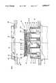
- the reference numeral 40denotes the central distributing chamber having at least three parts and into which the disks to be treated are fed and from which they are retrieved after the treatment from and to workpiece input and output chambers 42, 42.
- the intermediate chambers 44, 44' and 44"are connected at three sides and at three ports to this central distributing chamber and in the illustrated embodiment three treatment chambers are connected to every intermediate chamber, which treatment chambers are identified in FIG. 2 schematically by 45, 46 and 47; 45', 46' 47' and 45", 46", 47".
- the communication between the distributing chamber and the intermediate chambers connected theretois given by the gates 48, 48' and 48", which are opened and closed by an actuating unit in accordance with the processing treatments to be made.
- first and second mechanismsare located in the central distributing chamber or in the intermediate chambers which are flanged thereonto; these conduit the transporting of the disks in accordance with the processing sequence into the individual chambers or out of these chambers, similar to the procedure described in connection with FIG. 1.
- FIG. 3illustrates the first and second mechanisms used in the embodiment of FIG. 1 and the interaction.
- the reference numerals, as far as used,are the same as those of FIG. 1.
- a plate 50is mounted to the robot arm 10 and controlled by the drive 11, so that the plate can reach under a disk and take it from the cassette in the lock chamber 1 and pass it on after a retreating and rotating of the robot arm from the position 10' into the position 10 (see FIG. 1) to the gripping devices 21 in the chamber 15.
- the second mechanismthe disks will thereafter be brought into the proper position opposite the opening of a treatment chamber in that it rotates around the axis 20'.
- a disk 51 located on the plateis just passed on to the gripping device 21 (and thus would be positioned under the opening 22 of FIG. 1), whereas a further disk 52 is illustrated under the opening 23 of the treatment chamber 25 rotated further (in case of a treble division rotated further by 120°).
- the inventive method for operating the vacuum apparatuswill now be explained based on FIG. 1 and is characterized in that the first transporting mechanism 10, 11, 12 located in the first distributing chamber 7 takes consecutively one workpiece out of a magazine 4 in the lock 1 and transports it along the course through the distributing chamber 7 into an intermediate chamber 15 and in that the second transporting mechanism 20, 21 located in the intermediate chamber takes the workpiece over from the first transporting mechanism 10, 11, 12 and keeps it ready in a position coaxial to a communication opening 22 or 23 between the intermediate chamber 15 and one of the treatment chambers 24 or 25.
- This method of operationis specifically characterized in case of a plurality of treatment chambers 24, 25 allocated to one intermediate chamber 15 and of elevating mechanisms 26, 27 for a raising and lowering transport of the disks into and out of the treatment chambers in which elevating mechanisms 26, 27 are located below the communication openings 22, 23 between the treatment chambers 24, 25 and the intermediate chamber 15 and in the intermediate chamber 15, in accordance with the invention in that the second transport mechanism 20, 21 places the workpiece which has been taken over from the first transport mechanism 10, 11, 12 onto one of the elevating mechanisms 26, 27 which transports the workpiece into a treatment chamber 24, 25 located above the elevating mechanisms 24, 25, and in that the workpiece is transported along the same path at a reversed sequence of the transporting steps back to its starting position.
- the method of operating the vacuum apparatuscan specifically be formed such that in case of at least two treatment chambers 24, 25 allocated to one respective intermediate chamber 15 each one of these treatment chambers is placed into operation and regenerated during consecutively following time intervals alternatively after being loaded, whereby during the regeneration of one treatment chamber the further chamber is placed into operation.
- a certain time span during which a disk is treated in this chamberis followed by a time span during which this chamber is regenerated.
- two treatment chambersbeing present such can be carried out alternatively such that the regenerating phase and the treatment phase are interchanged continuously.
- the method of operating the vacuum apparatuscan be designed in accordance with the invention also such that instead of an elevating mechanism 26 or 27 a magazine having a supply of disks is located in an intermediate chamber and that then an intermediate chamber with a plurality for instance three treatment chambers allocated thereto is put into operation as a unit which is functionable independently from the rest of the vacuum apparatus, in other words a unit which can operate autonomously if for instance the other parts of the vacuum apparatus are out of operation due to an operational break-down.
- the vacuum apparatuscomprises elevating mechanisms located in every intermediate chamber present, which are operative to bring a disk placed onto the elevating mechanism into a treatment chamber located above the intermediate chamber.
- the disk shaped workpiecemust be secured to the support of the elevating mechanism, i.e. the workpiece must be held at its edge such that it maintains a predetermined position.
- the disksgrow together with such holding devices and adhere to these devices. If the treatment, on the other hand is an etching process the holding devices are etched too and the material which is removed from the disks could thereby soil the surface of the disk. During a cleaning etching of the disk by a cathode atomization the holding devices cause also distortions of the potential and as a consequence thereof often a kind of a halo or shade.
- the disk to be treatedshould be positioned on the support of the elevating mechanism further at a predetermined orientation of its position before the disk is transported into the treatment chamber.
- the diskhas for instance a contour which differs from the shape of a circle whereby a segment of the circle is cut off which serves for an indicating of the orientation of the crystals and the support for the disk has the same contour which differs from the shape of a circle and the disk must be held and transported precisely oriented relative to the support.
- an elevating mechanismis thus necessary in the shape of a specific elevating table with holding devices which are in a position to bring the workpiece onto the support in an exactly oriented position and lock the workpiece during its transport and without they themselves being exposed during the treatment of the workpiece to the influence of this treatment.
- the elevating table to be used in the vacuum apparatusshould, furthermore enable a treatment of the workpiece in the treatment chamber at predetermined set temperatures which must be held precisely constant. To this end a supplying of heat against the lower surface of the workpiece or a cooling thereof may be needed.
- an elevating tableserves for the rising and lowering transport of a disk shaped workpiece which has a movable workpiece support at which holding members are arranged pivotably to pivot into a holding position and out of holding position, such to move them shortly before the movable support reaches a treatment position into the release position and to move them in this position during the rest of the transport movement of the support into the treatment station until it moves behind a cover which protects the holding devices from the influences of the treatment of the workpiece.
- the workpiece supportis provided with a heating plate which is heatable by a heating element and with a plurality of channels opening at the surface of the support and which are jointly connected to a gas supply line in order to generate between support and workpiece a gas cushion as a homogenous heat conducting means for a heating of the workpiece.
- the gas cushionserves for an absolutely equal heat distribution under the workpiece.
- a dead weight load in the form of a loose ringis used which comes to lie at the outer edge of the workpiece in the treatment station. This ring has, furthermore, the duty to keep the annular gap between the support which carries the workpiece and the cover closed.
- a ringwhich rests only on the edge of the support but not on the edge of the workpiece such that the latter can also be transported in a freely resting condition.
- the ringrests preferably along the entire edge of the workpiece if a sealing action for the gas cushion is to be reached between the workpiece and the support.
- the ringcan be mounted by a spring bellows gas tight to the housing of the vacuum apparatus whereby also the elastic action of the spring bellows can be utilized to counteract the pressure of the gas cushion. If, however, the workpiece must be treated upto the outermost edge the ring can rest also by hooks located at its inner edge on the edge of the workpiece such that, except for the areas of the hooks, the largest part of the edge of the workpiece is heated.
- the elevating table with the holding members which can be pivoted into a holding condition and out of the holding conditionhas the advantage that the holding members protected in the position away from the holding position behind the cover can not get bonded or attached, to the workpiece by the influences of the treatment. If, however, the workpiece gets bonded to the ring resting on the edge of the workpiece the pivotable holding members operate in their position pivoted inwards toward the workpiece to separate during the reverse movement of the elevating table into its starting position, the workpiece by tearing the ring off.
- FIG. 4illustrates the most important parts of one of the elevating mechanisms 26 and 27 illustrated in FIG. 1 and which are designed respectively as elevating table for a rising and lowering movement of a workpiece inside of an intermediate chamber 15.
- the elevating table 26is illustrated in FIG. 4 in the so-called loading position in which a disk shaped workpiece 61 is placed on a workpiece support 62 consisting of several parts and specifically onto the central part 63 which in the illustrated example is provided with a heating plate 64 which is heated by a heating element and which heating plate has a plurality of vertical through bores through which a gas can flow inbetween the disk shaped workpiece 61 and the upper surface of the heating plate 64.
- the heating elementcan heat the heating plate up to a temperatures over 500° C.
- the heated gasacts then as heat conducting medium in order to completely evenly heat the workpiece over its entire surface.
- Useis made here preferably of the same gas which is used by a treatment made in the vacuum apparatus because a gas tight seal at the edge of the heating plate can be achieved only with large difficulties.
- a flange 67 located under the heating plate 64is used for the mounting of the heating element 65 and for the gas supply to the through bores in the heating plate.
- This heating plate and the flange 67are mounted together onto a further flange 68 which contains channels 69 of a rapid cooling system.
- the flange 68is mounted gas tight by means of a thin walled tube 70 in a temperature insulated fashion to an also cooled and electrically insulated mounted part 71.
- the workpiece support 62which can be moved upwards and downwards includes also mounting members 72 and 73 mounted pivotably thereto.
- FIG. 7discloses that two of such mounting members 72 are present at the one side and one mounting member 73 is present at the opposite side.
- the mounting membersare pivoted from a position 72a and 73a, in which position they are remote from an workpiece engaging position into the position 72b and 73b in which position they are in a engaging position. To this end they are pivoted around an axis 74 extending parallel to the center axis of the workpiece support 62. If necessary a correction of the position of the workpiece 62 its support is made during this movement, which will be explained in detail later on based on FIG. 7.
- the mounting members 72 and 73consist each of a rod shaped body 75 which is supported in a bearing 76 for rotation around its axis. Each mounting member can be pressed downwards against the action of a pressure spring 77 supported on the bearing and surrounding the rod shaped body 75.
- a cylindrically shaped outer member 78belongs also to the workpiece support 62 which can be moved upwards and downwards and within which the mounting members 72 and 73 are arranged for a pivotal movement.
- the elevating table 26extends from below through a recess in the wall 79 of the intermediate chamber 15 and this elevating table is flanged at the lower side onto this wall 79.
- a treatment chamber 24is located above the intermediate chamber 15 which two chambers communicate via a communicating opening 22 in the wall 80 located therebetween.
- the elevating table 26acts, therefore, not only for a rising and lowering transport of the workpieces but forms at the same instance a seal which separates the intermediate chamber 15 from the process chamber in a gas tight manner.
- annular cover 83is mounted to the wall 80 of the chamber and inside of the treatment chamber. Under this cover a loose ring 84 rests on the edge of the wall of the chamber and is guided in the opening 22. At its inner edge this ring 84 has hooks 85 distributed along its circumference.
- FIG. 5the workpiece support 62 is illustrated in a position risen into an intermediate station. Thereby the workpiece 61 resting on the support has lifted somewhat and the ring hangs by means of its hooks 85 on the edge of the workpiece such that latter is pressed against the heating plate 64 and is secured against a lateral sliding away.
- the ringacts thereby also as a dead weight loading in order to act against the earlier mentioned gas cushion between the workpiece and the heating plate.
- This ring 84has the further duty of covering the annular gap present between the cover 83 and the workpiece which has been risen on the support in order to protect the parts located thereunder from the influence of the treatment taking place in the treatment chamber.
- the mounting members 72 and 73are illustrated in a position remote from the mounting position, i.e. pivoted toward the outside.
- the workpiece support 62is illustrated in FIG. 6 risen up into its end position and is located at the treatment position. This position is reached when the cylindrical outer member 78 of the support 62 has been moved onto the edge of the wall 15 of the chamber 80 which is shaped as valve seal 81.
- the workpiece 61projects then over the cover 83 and is fully exposed to the treatment in the treatment chamber 24.
- the mounting members 72 and 73are pressed at the lower side against the cover 83 where they are slid inwards against the action of the spring 77. In this position under the cover 83 these mounting members 72 and 73 are protected from the influences of the treatment of the workpieces.
- FIG. 6different embodiments are illustrated at the right hand side and the left hand side and the movable ring 84 is only visible at the left hand side.
- a annular shield 86is illustrated in the right hand side of this figure which shield 86 is mounted to the support 62 and covers the annular gap between the cover 83 and the workpiece in order to protect the part located there below from the influences of the treatment chamber.
- This shield in the shape of a groovemust receive during coating treatments the coatings which grow slowly, e.g. an aluminum layer which can be as thick a 7 millimeters. Such coatings can also grow on the cover 83 for which reason this cover is easyly exchangeable and accessible from the treatment chamber 24, which is also true for the loose ring 84 and the shield 86.
- the right hand side of FIG. 6illustrates a possible embodiment having only one workpiece supporting plate, i.e. without a heating plate.
- FIG. 7illustrates a top view of the loose ring 84 with the hooks 85 located at its inner edge as well as the mounting members 72 and 73 for acting together with the disk shaped workpiece 61 illustrated with broken lines.
- the direction of vieworiginates at the treatemnt chamber 24 when the cover 83 is removed.
- FIG. 7illustrates the position after the workpiece support 62 has reached the intermediate position according to FIG. 5 but before the pivoting movement of the mounting members 72 and 73 towards the outside.
- the illustration according to FIG. 7is identical to the situation of the loading position according to FIG. 4 after the mounting members have been pivoted toward the inside if one imagines the loose ring 84 of FIG. 4 to lie in a plane above the workpiece 61 and the mounting members.
- the two situations mentioned beforerepeat themselves during the transporting of the workpiece from the treating position back into the loading position. Twice during every treatment cycle with a to and from transport, namely always during the pivoting movement of the mounting members 72 and 73 towards the inside into the position in accordance with FIG. 7 the orientation of the workpiece is corrected.
- the two mounting members 72are pivotted initially around axes 87 extending parallel to the center axis and not particularly illustrated in FIG. 4 and pressed firmly against a mechanical abutment.
- the mounting member 73is thereafter pivoted inwards around the axis 74 also illustrated in FIG. 4.
- the mounting memberpresses the workpiece 61 with the edge of the segment 61a (or the flat) softly against the two mounting members 72 and corrects thereby the orientation of the workpieces if the mounting members 72 are not contacted at the same time by the segment edge 61a, i.e. if the mounting members 72 and this edge 61a have not been oriented beforehand parallel.
- a shifting of the workpiece in the direction against the axis 88 during the procedure of correcting the orientationcan be limited in both positions, namely in the loading position by the here not described means for transporting the workpiece from one to the other station and in the intermediate station by the loose ring 84 or parts mounted thereto.
Landscapes
- Engineering & Computer Science (AREA)
- Power Engineering (AREA)
- Condensed Matter Physics & Semiconductors (AREA)
- General Physics & Mathematics (AREA)
- Manufacturing & Machinery (AREA)
- Computer Hardware Design (AREA)
- Physics & Mathematics (AREA)
- Microelectronics & Electronic Packaging (AREA)
- Robotics (AREA)
- Container, Conveyance, Adherence, Positioning, Of Wafer (AREA)
- Coating Apparatus (AREA)
- Physical Vapour Deposition (AREA)
- Drying Of Semiconductors (AREA)
- Applications Or Details Of Rotary Compressors (AREA)
- Electron Tubes For Measurement (AREA)
- Manipulator (AREA)
- Fluid-Driven Valves (AREA)
Abstract
Description
Claims (22)
Applications Claiming Priority (4)
| Application Number | Priority Date | Filing Date | Title |
|---|---|---|---|
| CH195188 | 1988-05-24 | ||
| CH1951/88 | 1988-05-24 | ||
| CH2722/88 | 1988-07-07 | ||
| CH272288 | 1988-07-15 |
Related Child Applications (1)
| Application Number | Title | Priority Date | Filing Date |
|---|---|---|---|
| US07/577,462DivisionUS5090900A (en) | 1988-05-24 | 1990-09-04 | Workpiece support for vacuum chamber |
Publications (1)
| Publication Number | Publication Date |
|---|---|
| US4990047Atrue US4990047A (en) | 1991-02-05 |
Family
ID=25689081
Family Applications (2)
| Application Number | Title | Priority Date | Filing Date |
|---|---|---|---|
| US07/356,872Expired - LifetimeUS4990047A (en) | 1988-05-24 | 1989-05-24 | Vacuum apparatus |
| US07/577,462Expired - LifetimeUS5090900A (en) | 1988-05-24 | 1990-09-04 | Workpiece support for vacuum chamber |
Family Applications After (1)
| Application Number | Title | Priority Date | Filing Date |
|---|---|---|---|
| US07/577,462Expired - LifetimeUS5090900A (en) | 1988-05-24 | 1990-09-04 | Workpiece support for vacuum chamber |
Country Status (6)
| Country | Link |
|---|---|
| US (2) | US4990047A (en) |
| EP (1) | EP0343530B1 (en) |
| JP (4) | JP3121602B2 (en) |
| AT (1) | ATE208961T1 (en) |
| DE (1) | DE58909880D1 (en) |
| ES (1) | ES2163388T3 (en) |
Cited By (73)
| Publication number | Priority date | Publication date | Assignee | Title |
|---|---|---|---|---|
| US5037262A (en)* | 1988-07-15 | 1991-08-06 | Balzers Aktiengesellschaft | Holding device for a disk and application therefor |
| US5098245A (en)* | 1989-02-24 | 1992-03-24 | U.S. Philips Corporation | High speed wafer handler |
| US5100285A (en)* | 1989-05-08 | 1992-03-31 | Balzers Aktiengesellschaft | Supporting and transport apparatus |
| US5228501A (en)* | 1986-12-19 | 1993-07-20 | Applied Materials, Inc. | Physical vapor deposition clamping mechanism and heater/cooler |
| US5234303A (en)* | 1990-05-15 | 1993-08-10 | Seiko Instruments Inc. | In-vacuum conveyance robot |
| US5288379A (en)* | 1991-12-04 | 1994-02-22 | Anelva Corporation | Multi-chamber integrated process system |
| US5308210A (en)* | 1990-07-23 | 1994-05-03 | Dainippon Screen Mfg. Co., Ltd. | Interface apparatus for transporting substrates between substrate processing apparatus |
| US5333986A (en)* | 1991-07-29 | 1994-08-02 | Tokyo Electron Limited | Transfer apparatus |
| US5352294A (en)* | 1993-01-28 | 1994-10-04 | White John M | Alignment of a shadow frame and large flat substrates on a support |
| US5364219A (en)* | 1991-06-24 | 1994-11-15 | Tdk Corporation | Apparatus for clean transfer of objects |
| US5388944A (en)* | 1992-02-07 | 1995-02-14 | Tokyo Electron Tohoku Kabushiki Kaisha | Vertical heat-treating apparatus and heat-treating process by using the vertical heat-treating apparatus |
| US5391035A (en)* | 1992-11-06 | 1995-02-21 | Applied Materials, Inc. | Micro-enviroment load lock |
| US5404894A (en)* | 1992-05-20 | 1995-04-11 | Tokyo Electron Kabushiki Kaisha | Conveyor apparatus |
| US5443346A (en)* | 1992-07-03 | 1995-08-22 | Shinko Electric Co., Ltd. | Wafer conveying system in a clean room |
| US5445491A (en)* | 1991-08-27 | 1995-08-29 | Toshiba Kikai Kabushiki Kaisha | Method for multichamber sheet-after-sheet type treatment |
| US5462397A (en)* | 1993-03-16 | 1995-10-31 | Tokyo Electron Limited | Processing apparatus |
| US5484011A (en)* | 1986-12-19 | 1996-01-16 | Applied Materials, Inc. | Method of heating and cooling a wafer during semiconductor processing |
| US5538390A (en)* | 1993-10-29 | 1996-07-23 | Applied Materials, Inc. | Enclosure for load lock interface |
| US5658115A (en)* | 1991-09-05 | 1997-08-19 | Hitachi, Ltd. | Transfer apparatus |
| US5697749A (en)* | 1992-07-17 | 1997-12-16 | Tokyo Electron Kabushiki Kaisha | Wafer processing apparatus |
| US5769588A (en)* | 1990-04-19 | 1998-06-23 | Applied Materials, Inc. | Dual cassette load lock |
| US5789878A (en)* | 1996-07-15 | 1998-08-04 | Applied Materials, Inc. | Dual plane robot |
| US5848670A (en)* | 1996-12-04 | 1998-12-15 | Applied Materials, Inc. | Lift pin guidance apparatus |
| US5855465A (en)* | 1996-04-16 | 1999-01-05 | Gasonics International | Semiconductor wafer processing carousel |
| US5863170A (en)* | 1996-04-16 | 1999-01-26 | Gasonics International | Modular process system |
| US6000905A (en)* | 1998-03-13 | 1999-12-14 | Toro-Lira; Guillermo L. | High speed in-vacuum flat panel display handler |
| US6034000A (en)* | 1997-07-28 | 2000-03-07 | Applied Materials, Inc. | Multiple loadlock system |
| US6045299A (en)* | 1998-04-13 | 2000-04-04 | International Business Machines Corp. | Unidirectional gate between interconnecting fluid transport regions |
| WO2000030155A1 (en)* | 1998-11-12 | 2000-05-25 | Tokyo Electron Limited | Buffer chamber and method for integrating physical and chemical vapor deposition chambers together in a processing system |
| US6092299A (en)* | 1997-09-05 | 2000-07-25 | Tokyo Electron Limited | Vacuum processing apparatus |
| US6132165A (en)* | 1998-02-23 | 2000-10-17 | Applied Materials, Inc. | Single drive, dual plane robot |
| US6136168A (en)* | 1993-01-21 | 2000-10-24 | Tdk Corporation | Clean transfer method and apparatus therefor |
| US6149368A (en)* | 1998-06-12 | 2000-11-21 | Advanced Micro Devices, Inc. | Wafer disk pad having one or more wafer loading points to facilitate vacuum wand wafer loading and unloading |
| US6183186B1 (en)* | 1997-08-29 | 2001-02-06 | Daitron, Inc. | Wafer handling system and method |
| US6207006B1 (en) | 1997-09-18 | 2001-03-27 | Tokyo Electron Limited | Vacuum processing apparatus |
| US6264706B1 (en)* | 1996-03-08 | 2001-07-24 | Kokusai Electric Co., Ltd. | Substrate processing apparatus with local exhaust for removing contaminants |
| US6352403B1 (en) | 1992-11-06 | 2002-03-05 | Applied Materials, Inc. | Controlled environment enclosure and mechanical interface |
| US20020034886A1 (en)* | 2000-09-15 | 2002-03-21 | Applied Materials, Inc. | Double dual slot load lock for process equipment |
| US6395094B1 (en)* | 1999-04-15 | 2002-05-28 | Tokyo Electron Limited | Process system with transfer unit for object to be processed |
| US20020133260A1 (en)* | 1996-09-11 | 2002-09-19 | Kouji Nishihata | Operating method of vacuum processing system and vacuum processing system |
| US20030152445A1 (en)* | 2002-02-08 | 2003-08-14 | Takayuki Yamagishi | Semiconductor processing apparatus comprising chamber partitioned into reaction and transfer sections |
| US20050016454A1 (en)* | 1999-12-15 | 2005-01-27 | Applied Materials, Inc. | Dual substrate loadlock process equipment |
| US20050051101A1 (en)* | 1999-03-08 | 2005-03-10 | Kuznetsov Vladimir Ivanovich | Method and device for rotating a wafer |
| US6877250B2 (en) | 1999-12-29 | 2005-04-12 | Asm International N.V. | Apparatus, method and system for the treatment of a wafer |
| US6883250B1 (en) | 2003-11-04 | 2005-04-26 | Asm America, Inc. | Non-contact cool-down station for wafers |
| US20050095088A1 (en)* | 2003-10-20 | 2005-05-05 | Applied Materials, Inc. | Load lock chamber for large area substrate processing system |
| US20050150757A1 (en)* | 1997-03-17 | 2005-07-14 | Applied Komatsu Technology, Inc. | Heated and cooled vacuum chamber shield |
| US20060151735A1 (en)* | 2004-06-14 | 2006-07-13 | Jae-Chull Lee | Curved slit valve door with flexible coupling |
| US20060182615A1 (en)* | 2001-09-21 | 2006-08-17 | Shinichi Kurita | Method for transferring substrates in a load lock chamber |
| US20060231027A1 (en)* | 2005-04-18 | 2006-10-19 | Tokyo Electron Limited | Load lock apparatus, processing system and substrate processing method |
| US20060273815A1 (en)* | 2005-06-06 | 2006-12-07 | Applied Materials, Inc. | Substrate support with integrated prober drive |
| US20070006936A1 (en)* | 2005-07-07 | 2007-01-11 | Applied Materials, Inc. | Load lock chamber with substrate temperature regulation |
| US20070166133A1 (en)* | 2006-01-13 | 2007-07-19 | Applied Materials, Inc. | Decoupled chamber body |
| US20070280816A1 (en)* | 2006-06-02 | 2007-12-06 | Shinichi Kurita | Multiple slot load lock chamber and method of operation |
| US20080029023A1 (en)* | 2004-05-17 | 2008-02-07 | Shibaura Mechatronics Corporation | Vacuum Processing Device |
| US20080087214A1 (en)* | 2006-08-04 | 2008-04-17 | Jae-Chull Lee | Load lock chamber with decoupled slit valve door seal compartment |
| US20080202416A1 (en)* | 2006-01-19 | 2008-08-28 | Provencher Timothy J | High temperature ALD inlet manifold |
| US20080251376A1 (en)* | 2004-05-17 | 2008-10-16 | Shibaura Mechatronics Corporation | Vacuum Processing Device and Method of Manufacturing Optical Disk |
| US20080251019A1 (en)* | 2007-04-12 | 2008-10-16 | Sriram Krishnaswami | System and method for transferring a substrate into and out of a reduced volume chamber accommodating multiple substrates |
| US20080282710A1 (en)* | 2007-05-15 | 2008-11-20 | Bartlett Allen J | Integral facet cryopump, water vapor pump, or high vacuum pump |
| CN100569996C (en)* | 2004-05-14 | 2009-12-16 | 爱德华兹真空股份有限公司 | Method and apparatus for transferring articles through load lock chamber under vacuum |
| US7845618B2 (en) | 2006-06-28 | 2010-12-07 | Applied Materials, Inc. | Valve door with ball coupling |
| US20120231628A1 (en)* | 2011-03-07 | 2012-09-13 | Novellus Systems Inc. | Reduction of a process volume of a processing chamber using a nested dynamic inert volume |
| US9388492B2 (en) | 2011-12-27 | 2016-07-12 | Asm America, Inc. | Vapor flow control apparatus for atomic layer deposition |
| US9574268B1 (en) | 2011-10-28 | 2017-02-21 | Asm America, Inc. | Pulsed valve manifold for atomic layer deposition |
| US10662527B2 (en) | 2016-06-01 | 2020-05-26 | Asm Ip Holding B.V. | Manifolds for uniform vapor deposition |
| US10998209B2 (en)* | 2019-05-31 | 2021-05-04 | Applied Materials, Inc. | Substrate processing platforms including multiple processing chambers |
| US20210187139A1 (en)* | 2017-11-07 | 2021-06-24 | Metall + Plastic Gmbh | Surface decontamination device and operating method |
| CN114080668A (en)* | 2019-07-12 | 2022-02-22 | 应用材料公司 | High density substrate processing system and method |
| US11257696B2 (en)* | 2016-10-18 | 2022-02-22 | Mattson Technology, Inc. | Systems and methods for workpiece processing |
| US11482434B2 (en) | 2016-10-18 | 2022-10-25 | Belting E-Town Semiconductor Technology Co., Ltd | Systems and methods for workpiece processing |
| US11492701B2 (en) | 2019-03-19 | 2022-11-08 | Asm Ip Holding B.V. | Reactor manifolds |
| US11830731B2 (en) | 2019-10-22 | 2023-11-28 | Asm Ip Holding B.V. | Semiconductor deposition reactor manifolds |
Families Citing this family (30)
| Publication number | Priority date | Publication date | Assignee | Title |
|---|---|---|---|---|
| US5094885A (en)* | 1990-10-12 | 1992-03-10 | Genus, Inc. | Differential pressure cvd chuck |
| JPH0552808U (en)* | 1991-12-24 | 1993-07-13 | 富士写真光機株式会社 | Projector projection lens |
| DE4235674C2 (en)* | 1992-10-22 | 2000-12-28 | Balzers Ag Liechtenstein | Chamber for the transport of workpieces in a vacuum atmosphere, chamber combination and method for transporting a workpiece |
| KR960009975B1 (en)* | 1993-04-26 | 1996-07-25 | 한국베리안 주식회사 | Heat treatment device for thin film using second space |
| US5447431A (en)* | 1993-10-29 | 1995-09-05 | Brooks Automation, Inc. | Low-gas temperature stabilization system |
| US5588827A (en)* | 1993-12-17 | 1996-12-31 | Brooks Automation Inc. | Passive gas substrate thermal conditioning apparatus and method |
| KR100356438B1 (en)* | 1993-12-17 | 2002-12-12 | 부룩스 오토메이션, 인코포레이티드 | Wafer Heating or Cooling System |
| US5791895A (en)* | 1994-02-17 | 1998-08-11 | Novellus Systems, Inc. | Apparatus for thermal treatment of thin film wafer |
| DE9407482U1 (en)* | 1994-05-05 | 1994-10-06 | Balzers und Leybold Deutschland Holding AG, 63450 Hanau | Functional device for a vacuum system for the treatment of disc-shaped workpieces |
| US5476549A (en)* | 1995-01-24 | 1995-12-19 | Cvd, Inc. | Process for an improved laminate of ZnSe and ZnS |
| US5680502A (en)* | 1995-04-03 | 1997-10-21 | Varian Associates, Inc. | Thin film heat treatment apparatus with conductively heated table and surrounding radiation shield |
| US6193506B1 (en) | 1995-05-24 | 2001-02-27 | Brooks Automation, Inc. | Apparatus and method for batch thermal conditioning of substrates |
| KR100238998B1 (en)* | 1995-07-26 | 2000-01-15 | 우치가사키 기이치로 | Heating furnace |
| US6113702A (en)* | 1995-09-01 | 2000-09-05 | Asm America, Inc. | Wafer support system |
| US6053982A (en)* | 1995-09-01 | 2000-04-25 | Asm America, Inc. | Wafer support system |
| US5881208A (en)* | 1995-12-20 | 1999-03-09 | Sematech, Inc. | Heater and temperature sensor array for rapid thermal processing thermal core |
| US6183565B1 (en)* | 1997-07-08 | 2001-02-06 | Asm International N.V | Method and apparatus for supporting a semiconductor wafer during processing |
| US5879461A (en)* | 1997-04-21 | 1999-03-09 | Brooks Automation, Inc. | Metered gas control in a substrate processing apparatus |
| US20010035403A1 (en) | 2000-05-18 | 2001-11-01 | Albert Wang | Method and structure for producing flat wafer chucks |
| US20030168174A1 (en) | 2002-03-08 | 2003-09-11 | Foree Michael Todd | Gas cushion susceptor system |
| US20060137609A1 (en)* | 2004-09-13 | 2006-06-29 | Puchacz Jerzy P | Multi-single wafer processing apparatus |
| KR100972255B1 (en)* | 2005-08-05 | 2010-07-23 | 어드밴스드 마이크로 패브리케이션 이큅먼트 인코퍼레이티드 아시아 | Semiconductor workpiece processing system and processing method |
| KR20100086490A (en) | 2007-10-24 | 2010-07-30 | 오씨 외를리콘 발처스 악티엔게젤샤프트 | Method for manufacturing workpieces and apparatus |
| US8092606B2 (en) | 2007-12-18 | 2012-01-10 | Asm Genitech Korea Ltd. | Deposition apparatus |
| US20120083129A1 (en) | 2010-10-05 | 2012-04-05 | Skyworks Solutions, Inc. | Apparatus and methods for focusing plasma |
| US9478428B2 (en)* | 2010-10-05 | 2016-10-25 | Skyworks Solutions, Inc. | Apparatus and methods for shielding a plasma etcher electrode |
| CN108007488B (en)* | 2017-11-29 | 2020-04-28 | 赫立科技(成都)有限公司 | A position adjustment device used in a vacuum chamber |
| RU2700872C1 (en)* | 2018-08-23 | 2019-09-23 | Акционерное общество "Объединенная двигателестроительная корпорация" (АО "ОДК") | Pyrolysis vacuum unit |
| US20210013069A1 (en)* | 2019-07-12 | 2021-01-14 | Applied Materials, Inc. | Multi-lid structure for semiconductor processing system |
| CN112391608A (en)* | 2020-11-13 | 2021-02-23 | 宁波沁圆科技有限公司 | CVD processing system and processing method |
Citations (14)
| Publication number | Priority date | Publication date | Assignee | Title |
|---|---|---|---|---|
| US3874525A (en)* | 1973-06-29 | 1975-04-01 | Ibm | Method and apparatus for handling workpieces |
| US4405435A (en)* | 1980-08-27 | 1983-09-20 | Hitachi, Ltd. | Apparatus for performing continuous treatment in vacuum |
| US4553069A (en)* | 1984-01-05 | 1985-11-12 | General Ionex Corporation | Wafer holding apparatus for ion implantation |
| US4592306A (en)* | 1983-12-05 | 1986-06-03 | Pilkington Brothers P.L.C. | Apparatus for the deposition of multi-layer coatings |
| WO1987006561A1 (en)* | 1986-04-28 | 1987-11-05 | Varian Associates, Inc. | Modular semiconductor wafer transport and processing system |
| US4705951A (en)* | 1986-04-17 | 1987-11-10 | Varian Associates, Inc. | Wafer processing system |
| US4709655A (en)* | 1985-12-03 | 1987-12-01 | Varian Associates, Inc. | Chemical vapor deposition apparatus |
| US4715637A (en)* | 1985-04-17 | 1987-12-29 | Hitachi, Ltd. | Grip device for sheet-like objects |
| US4747928A (en)* | 1985-08-08 | 1988-05-31 | Anelva Corporation | Substrate processing apparatus including wafer transporting and substrate cooling mechanisms |
| EP0276061A1 (en)* | 1987-01-15 | 1988-07-27 | Varian Associates, Inc. | Rapid thermal chemical vapour deposition apparatus |
| US4828224A (en)* | 1987-10-15 | 1989-05-09 | Epsilon Technology, Inc. | Chemical vapor deposition system |
| US4874312A (en)* | 1985-03-11 | 1989-10-17 | Hailey Robert W | Heating and handling system for objects |
| US4909695A (en)* | 1986-04-04 | 1990-03-20 | Materials Research Corporation | Method and apparatus for handling and processing wafer-like materials |
| US4917556A (en)* | 1986-04-28 | 1990-04-17 | Varian Associates, Inc. | Modular wafer transport and processing system |
Family Cites Families (25)
| Publication number | Priority date | Publication date | Assignee | Title |
|---|---|---|---|---|
| US3930684A (en)* | 1971-06-22 | 1976-01-06 | Lasch Jr Cecil A | Automatic wafer feeding and pre-alignment apparatus and method |
| JPH0670897B2 (en)* | 1982-05-25 | 1994-09-07 | バリアン・アソシエイツ・インコ−ポレイテッド | Device for removing heat from thin and flexible articles |
| JPS58207217A (en)* | 1982-05-28 | 1983-12-02 | Fujitsu Ltd | Object transfer method in vacuum |
| JPS59129778A (en)* | 1983-01-13 | 1984-07-26 | Tokuda Seisakusho Ltd | Sputtering device |
| JPH0669027B2 (en)* | 1983-02-21 | 1994-08-31 | 株式会社日立製作所 | Method for forming thin film on semiconductor wafer |
| JPS6074531A (en)* | 1983-09-30 | 1985-04-26 | Hitachi Ltd | Vacuum processing equipment |
| JPH06105742B2 (en)* | 1983-11-28 | 1994-12-21 | 株式会社日立製作所 | Vacuum processing method and device |
| JPS60125371A (en)* | 1983-12-09 | 1985-07-04 | Hitachi Ltd | Device for heating substrate in vacuum |
| US4603466A (en)* | 1984-02-17 | 1986-08-05 | Gca Corporation | Wafer chuck |
| JPS60238134A (en)* | 1984-04-16 | 1985-11-27 | Tokuda Seisakusho Ltd | Vacuum processing equipment |
| JPS611017A (en)* | 1984-06-13 | 1986-01-07 | Kokusai Electric Co Ltd | Heat treatment equipment for semiconductor substrates |
| US4534816A (en)* | 1984-06-22 | 1985-08-13 | International Business Machines Corporation | Single wafer plasma etch reactor |
| JPS6130030A (en)* | 1984-07-12 | 1986-02-12 | インタ−ナショナル ビジネス マシ−ンズ コ−ポレ−ション | Method of annealing multi-element semiconductor |
| JPS61107720A (en)* | 1984-10-31 | 1986-05-26 | Hitachi Ltd | Molecular beam epitaxy equipment |
| JPS61112312A (en)* | 1984-11-07 | 1986-05-30 | Hitachi Ltd | Vacuum continuous processing equipment |
| US4693777A (en)* | 1984-11-30 | 1987-09-15 | Kabushiki Kaisha Toshiba | Apparatus for producing semiconductor devices |
| JPS6251170U (en)* | 1985-09-19 | 1987-03-30 | ||
| JP2540524B2 (en)* | 1985-10-24 | 1996-10-02 | テキサス インスツルメンツ インコ−ポレイテツド | Wafer support |
| CA1331163C (en)* | 1986-04-18 | 1994-08-02 | Applied Materials, Inc. | Multiple-processing and contamination-free plasma etching system |
| US4715921A (en)* | 1986-10-24 | 1987-12-29 | General Signal Corporation | Quad processor |
| GB8709064D0 (en)* | 1986-04-28 | 1987-05-20 | Varian Associates | Wafer handling arm |
| JPS62277234A (en)* | 1986-05-23 | 1987-12-02 | Canon Inc | electrostatic chuck device |
| DE3633386A1 (en)* | 1986-10-01 | 1988-04-14 | Leybold Ag | Method and device for treating substrates in a vacuum |
| US4874273A (en)* | 1987-03-16 | 1989-10-17 | Hitachi, Ltd. | Apparatus for holding and/or conveying articles by fluid |
| DE3885240D1 (en)* | 1987-12-03 | 1993-12-02 | Balzers Hochvakuum | Method and device for transferring thermal energy to or from a plate-shaped substrate. |
- 1989
- 1989-05-19DEDE58909880Tpatent/DE58909880D1/ennot_activeExpired - Lifetime
- 1989-05-19ESES89109054Tpatent/ES2163388T3/ennot_activeExpired - Lifetime
- 1989-05-19EPEP89109054Apatent/EP0343530B1/ennot_activeExpired - Lifetime
- 1989-05-19ATAT89109054Tpatent/ATE208961T1/ennot_activeIP Right Cessation
- 1989-05-24USUS07/356,872patent/US4990047A/ennot_activeExpired - Lifetime
- 1989-05-24JPJP12901389Apatent/JP3121602B2/ennot_activeExpired - Lifetime
- 1990
- 1990-09-04USUS07/577,462patent/US5090900A/ennot_activeExpired - Lifetime
- 1998
- 1998-09-16JPJP10261550Apatent/JPH11145252A/ennot_activeWithdrawn
- 1999
- 1999-04-16JPJP10972699Apatent/JP3455468B2/ennot_activeExpired - Lifetime
- 2005
- 2005-01-12JPJP2005005068Apatent/JP4012941B2/ennot_activeExpired - Lifetime
Patent Citations (14)
| Publication number | Priority date | Publication date | Assignee | Title |
|---|---|---|---|---|
| US3874525A (en)* | 1973-06-29 | 1975-04-01 | Ibm | Method and apparatus for handling workpieces |
| US4405435A (en)* | 1980-08-27 | 1983-09-20 | Hitachi, Ltd. | Apparatus for performing continuous treatment in vacuum |
| US4592306A (en)* | 1983-12-05 | 1986-06-03 | Pilkington Brothers P.L.C. | Apparatus for the deposition of multi-layer coatings |
| US4553069A (en)* | 1984-01-05 | 1985-11-12 | General Ionex Corporation | Wafer holding apparatus for ion implantation |
| US4874312A (en)* | 1985-03-11 | 1989-10-17 | Hailey Robert W | Heating and handling system for objects |
| US4715637A (en)* | 1985-04-17 | 1987-12-29 | Hitachi, Ltd. | Grip device for sheet-like objects |
| US4747928A (en)* | 1985-08-08 | 1988-05-31 | Anelva Corporation | Substrate processing apparatus including wafer transporting and substrate cooling mechanisms |
| US4709655A (en)* | 1985-12-03 | 1987-12-01 | Varian Associates, Inc. | Chemical vapor deposition apparatus |
| US4909695A (en)* | 1986-04-04 | 1990-03-20 | Materials Research Corporation | Method and apparatus for handling and processing wafer-like materials |
| US4705951A (en)* | 1986-04-17 | 1987-11-10 | Varian Associates, Inc. | Wafer processing system |
| WO1987006561A1 (en)* | 1986-04-28 | 1987-11-05 | Varian Associates, Inc. | Modular semiconductor wafer transport and processing system |
| US4917556A (en)* | 1986-04-28 | 1990-04-17 | Varian Associates, Inc. | Modular wafer transport and processing system |
| EP0276061A1 (en)* | 1987-01-15 | 1988-07-27 | Varian Associates, Inc. | Rapid thermal chemical vapour deposition apparatus |
| US4828224A (en)* | 1987-10-15 | 1989-05-09 | Epsilon Technology, Inc. | Chemical vapor deposition system |
Cited By (125)
| Publication number | Priority date | Publication date | Assignee | Title |
|---|---|---|---|---|
| US5228501A (en)* | 1986-12-19 | 1993-07-20 | Applied Materials, Inc. | Physical vapor deposition clamping mechanism and heater/cooler |
| US5484011A (en)* | 1986-12-19 | 1996-01-16 | Applied Materials, Inc. | Method of heating and cooling a wafer during semiconductor processing |
| US5037262A (en)* | 1988-07-15 | 1991-08-06 | Balzers Aktiengesellschaft | Holding device for a disk and application therefor |
| US5098245A (en)* | 1989-02-24 | 1992-03-24 | U.S. Philips Corporation | High speed wafer handler |
| US5100285A (en)* | 1989-05-08 | 1992-03-31 | Balzers Aktiengesellschaft | Supporting and transport apparatus |
| US5769588A (en)* | 1990-04-19 | 1998-06-23 | Applied Materials, Inc. | Dual cassette load lock |
| US6599076B2 (en) | 1990-04-19 | 2003-07-29 | Applied Materials, Inc. | Dual cassette load lock |
| US6454508B2 (en) | 1990-04-19 | 2002-09-24 | Applied Materials, Inc. | Dual cassette load lock |
| US6454519B1 (en)* | 1990-04-19 | 2002-09-24 | Applied Materials, Inc. | Dual cassette load lock |
| US5234303A (en)* | 1990-05-15 | 1993-08-10 | Seiko Instruments Inc. | In-vacuum conveyance robot |
| US5308210A (en)* | 1990-07-23 | 1994-05-03 | Dainippon Screen Mfg. Co., Ltd. | Interface apparatus for transporting substrates between substrate processing apparatus |
| US5364219A (en)* | 1991-06-24 | 1994-11-15 | Tdk Corporation | Apparatus for clean transfer of objects |
| US5333986A (en)* | 1991-07-29 | 1994-08-02 | Tokyo Electron Limited | Transfer apparatus |
| US5445491A (en)* | 1991-08-27 | 1995-08-29 | Toshiba Kikai Kabushiki Kaisha | Method for multichamber sheet-after-sheet type treatment |
| US5658115A (en)* | 1991-09-05 | 1997-08-19 | Hitachi, Ltd. | Transfer apparatus |
| US5288379A (en)* | 1991-12-04 | 1994-02-22 | Anelva Corporation | Multi-chamber integrated process system |
| US5388944A (en)* | 1992-02-07 | 1995-02-14 | Tokyo Electron Tohoku Kabushiki Kaisha | Vertical heat-treating apparatus and heat-treating process by using the vertical heat-treating apparatus |
| US5404894A (en)* | 1992-05-20 | 1995-04-11 | Tokyo Electron Kabushiki Kaisha | Conveyor apparatus |
| US5443346A (en)* | 1992-07-03 | 1995-08-22 | Shinko Electric Co., Ltd. | Wafer conveying system in a clean room |
| US5697749A (en)* | 1992-07-17 | 1997-12-16 | Tokyo Electron Kabushiki Kaisha | Wafer processing apparatus |
| US5391035A (en)* | 1992-11-06 | 1995-02-21 | Applied Materials, Inc. | Micro-enviroment load lock |
| US6352403B1 (en) | 1992-11-06 | 2002-03-05 | Applied Materials, Inc. | Controlled environment enclosure and mechanical interface |
| US6136168A (en)* | 1993-01-21 | 2000-10-24 | Tdk Corporation | Clean transfer method and apparatus therefor |
| US5611865A (en)* | 1993-01-28 | 1997-03-18 | Applied Materials, Inc. | Alignment of a shadow frame and large flat substrates on a heated support |
| US5352294A (en)* | 1993-01-28 | 1994-10-04 | White John M | Alignment of a shadow frame and large flat substrates on a support |
| US5462397A (en)* | 1993-03-16 | 1995-10-31 | Tokyo Electron Limited | Processing apparatus |
| US5630690A (en)* | 1993-10-29 | 1997-05-20 | Applied Materials, Inc. | Enclosure for load lock interface |
| US5538390A (en)* | 1993-10-29 | 1996-07-23 | Applied Materials, Inc. | Enclosure for load lock interface |
| US6264706B1 (en)* | 1996-03-08 | 2001-07-24 | Kokusai Electric Co., Ltd. | Substrate processing apparatus with local exhaust for removing contaminants |
| US5863170A (en)* | 1996-04-16 | 1999-01-26 | Gasonics International | Modular process system |
| US5855465A (en)* | 1996-04-16 | 1999-01-05 | Gasonics International | Semiconductor wafer processing carousel |
| US5789878A (en)* | 1996-07-15 | 1998-08-04 | Applied Materials, Inc. | Dual plane robot |
| US20020133256A1 (en)* | 1996-09-11 | 2002-09-19 | Kouji Nishihata | Operating method of vacuum processing system and vacuum processing system |
| US20020133260A1 (en)* | 1996-09-11 | 2002-09-19 | Kouji Nishihata | Operating method of vacuum processing system and vacuum processing system |
| US6941185B2 (en)* | 1996-09-11 | 2005-09-06 | Hitachi, Ltd. | Operating method of vacuum processing system and vacuum processing system |
| US6853872B2 (en)* | 1996-09-11 | 2005-02-08 | Hitachi, Ltd. | Operating method of vacuum processing system and vacuum processing system |
| US5848670A (en)* | 1996-12-04 | 1998-12-15 | Applied Materials, Inc. | Lift pin guidance apparatus |
| US20050150757A1 (en)* | 1997-03-17 | 2005-07-14 | Applied Komatsu Technology, Inc. | Heated and cooled vacuum chamber shield |
| US6450750B1 (en) | 1997-07-28 | 2002-09-17 | Applied Materials, Inc. | Multiple loadlock system |
| US6034000A (en)* | 1997-07-28 | 2000-03-07 | Applied Materials, Inc. | Multiple loadlock system |
| US6183186B1 (en)* | 1997-08-29 | 2001-02-06 | Daitron, Inc. | Wafer handling system and method |
| US6092299A (en)* | 1997-09-05 | 2000-07-25 | Tokyo Electron Limited | Vacuum processing apparatus |
| US6207006B1 (en) | 1997-09-18 | 2001-03-27 | Tokyo Electron Limited | Vacuum processing apparatus |
| US6132165A (en)* | 1998-02-23 | 2000-10-17 | Applied Materials, Inc. | Single drive, dual plane robot |
| US6000905A (en)* | 1998-03-13 | 1999-12-14 | Toro-Lira; Guillermo L. | High speed in-vacuum flat panel display handler |
| US6149498A (en)* | 1998-04-13 | 2000-11-21 | International Business Machines Corporation | Semiconductor wafer handling system |
| US6045299A (en)* | 1998-04-13 | 2000-04-04 | International Business Machines Corp. | Unidirectional gate between interconnecting fluid transport regions |
| US6149368A (en)* | 1998-06-12 | 2000-11-21 | Advanced Micro Devices, Inc. | Wafer disk pad having one or more wafer loading points to facilitate vacuum wand wafer loading and unloading |
| US6183564B1 (en) | 1998-11-12 | 2001-02-06 | Tokyo Electron Limited | Buffer chamber for integrating physical and chemical vapor deposition chambers together in a processing system |
| GB2349893B (en)* | 1998-11-12 | 2003-07-02 | Tokyo Electron Ltd | Buffer chamber and method for intergrating physical and chemical vapor deposition chambers together in a processing system |
| WO2000030155A1 (en)* | 1998-11-12 | 2000-05-25 | Tokyo Electron Limited | Buffer chamber and method for integrating physical and chemical vapor deposition chambers together in a processing system |
| KR100392966B1 (en)* | 1998-11-12 | 2003-07-31 | 도쿄 엘렉트론 가부시키가이샤 | Buffer chamber and method for integrating physical and chemical vapor deposition chambers together in a processing system |
| GB2349893A (en)* | 1998-11-12 | 2000-11-15 | Tokyo Electron Ltd | Buffer chamber and method for intergrating physical and chemical vapor deposition chambers together in a processing system |
| DE19982566B4 (en)* | 1998-11-12 | 2009-02-26 | Tokyo Electron Arizona Inc., Gilbert | Device and method for processing a substrate |
| US20050051101A1 (en)* | 1999-03-08 | 2005-03-10 | Kuznetsov Vladimir Ivanovich | Method and device for rotating a wafer |
| US7351293B2 (en) | 1999-03-08 | 2008-04-01 | Asm International N.V. | Method and device for rotating a wafer |
| US6395094B1 (en)* | 1999-04-15 | 2002-05-28 | Tokyo Electron Limited | Process system with transfer unit for object to be processed |
| US20050016454A1 (en)* | 1999-12-15 | 2005-01-27 | Applied Materials, Inc. | Dual substrate loadlock process equipment |
| US7641434B2 (en) | 1999-12-15 | 2010-01-05 | Applied Materials, Inc. | Dual substrate loadlock process equipment |
| US6949143B1 (en) | 1999-12-15 | 2005-09-27 | Applied Materials, Inc. | Dual substrate loadlock process equipment |
| US6877250B2 (en) | 1999-12-29 | 2005-04-12 | Asm International N.V. | Apparatus, method and system for the treatment of a wafer |
| US7105463B2 (en) | 2000-09-15 | 2006-09-12 | Applied Materials, Inc. | Load lock chamber having two dual slot regions |
| US20020034886A1 (en)* | 2000-09-15 | 2002-03-21 | Applied Materials, Inc. | Double dual slot load lock for process equipment |
| US8616820B2 (en) | 2001-09-21 | 2013-12-31 | Applied Materials, Inc. | Double dual slot load lock chamber |
| US7316966B2 (en) | 2001-09-21 | 2008-01-08 | Applied Materials, Inc. | Method for transferring substrates in a load lock chamber |
| US20060182615A1 (en)* | 2001-09-21 | 2006-08-17 | Shinichi Kurita | Method for transferring substrates in a load lock chamber |
| US20080044259A1 (en)* | 2001-09-21 | 2008-02-21 | Shinichi Kurita | Double dual slot load lock chamber |
| US20050118001A1 (en)* | 2002-02-08 | 2005-06-02 | Takayuki Yamagishi | Semiconductor processing apparatus comprising chamber partitioned into reaction and transfer sections |
| US6899507B2 (en)* | 2002-02-08 | 2005-05-31 | Asm Japan K.K. | Semiconductor processing apparatus comprising chamber partitioned into reaction and transfer sections |
| US7021881B2 (en) | 2002-02-08 | 2006-04-04 | Asm Japan K.K. | Semiconductor processing apparatus comprising chamber partitioned into reaction and transfer sections |
| US20030152445A1 (en)* | 2002-02-08 | 2003-08-14 | Takayuki Yamagishi | Semiconductor processing apparatus comprising chamber partitioned into reaction and transfer sections |
| US7651315B2 (en) | 2003-10-20 | 2010-01-26 | Applied Materials, Inc. | Large area substrate transferring method for aligning with horizontal actuation of lever arm |
| US7207766B2 (en) | 2003-10-20 | 2007-04-24 | Applied Materials, Inc. | Load lock chamber for large area substrate processing system |
| US20070140814A1 (en)* | 2003-10-20 | 2007-06-21 | Shinichi Kurita | Large area substrate transferring method |
| US20050095088A1 (en)* | 2003-10-20 | 2005-05-05 | Applied Materials, Inc. | Load lock chamber for large area substrate processing system |
| US6883250B1 (en) | 2003-11-04 | 2005-04-26 | Asm America, Inc. | Non-contact cool-down station for wafers |
| US7147720B2 (en) | 2003-11-04 | 2006-12-12 | Asm America, Inc. | Non-contact cool-down station for wafers |
| US20050091992A1 (en)* | 2003-11-04 | 2005-05-05 | Ravinder Aggarwal | Non-contact cool-down station for wafers |
| US20050145180A1 (en)* | 2003-11-04 | 2005-07-07 | Ravinder Aggarwal | Non-contact cool-down station for wafers |
| CN100569996C (en)* | 2004-05-14 | 2009-12-16 | 爱德华兹真空股份有限公司 | Method and apparatus for transferring articles through load lock chamber under vacuum |
| US8506774B2 (en) | 2004-05-17 | 2013-08-13 | Shibaura Mechatronics Corporation | Vacuum processing device |
| US20080251376A1 (en)* | 2004-05-17 | 2008-10-16 | Shibaura Mechatronics Corporation | Vacuum Processing Device and Method of Manufacturing Optical Disk |
| US20080029023A1 (en)* | 2004-05-17 | 2008-02-07 | Shibaura Mechatronics Corporation | Vacuum Processing Device |
| US20060151735A1 (en)* | 2004-06-14 | 2006-07-13 | Jae-Chull Lee | Curved slit valve door with flexible coupling |
| US7497414B2 (en) | 2004-06-14 | 2009-03-03 | Applied Materials, Inc. | Curved slit valve door with flexible coupling |
| US20060231027A1 (en)* | 2005-04-18 | 2006-10-19 | Tokyo Electron Limited | Load lock apparatus, processing system and substrate processing method |
| US8196619B2 (en) | 2005-04-18 | 2012-06-12 | Tokyo Electron Limited | Load lock apparatus, processing system and substrate processing method |
| US20100040437A1 (en)* | 2005-04-18 | 2010-02-18 | Tokyo Electron Limited | Load lock apparatus, processing system and substrate processing method |
| US7624772B2 (en)* | 2005-04-18 | 2009-12-01 | Tokyo Electron Limited | Load lock apparatus, processing system and substrate processing method |
| US20060273815A1 (en)* | 2005-06-06 | 2006-12-07 | Applied Materials, Inc. | Substrate support with integrated prober drive |
| US20070006936A1 (en)* | 2005-07-07 | 2007-01-11 | Applied Materials, Inc. | Load lock chamber with substrate temperature regulation |
| US7845891B2 (en) | 2006-01-13 | 2010-12-07 | Applied Materials, Inc. | Decoupled chamber body |
| US20070166133A1 (en)* | 2006-01-13 | 2007-07-19 | Applied Materials, Inc. | Decoupled chamber body |
| US8372201B2 (en) | 2006-01-19 | 2013-02-12 | Asm America, Inc. | High temperature ALD inlet manifold |
| US20110162580A1 (en)* | 2006-01-19 | 2011-07-07 | Asm America, Inc. | High temperature ald inlet manifold |
| US20080202416A1 (en)* | 2006-01-19 | 2008-08-28 | Provencher Timothy J | High temperature ALD inlet manifold |
| US7918938B2 (en) | 2006-01-19 | 2011-04-05 | Asm America, Inc. | High temperature ALD inlet manifold |
| US7665951B2 (en) | 2006-06-02 | 2010-02-23 | Applied Materials, Inc. | Multiple slot load lock chamber and method of operation |
| US20070280816A1 (en)* | 2006-06-02 | 2007-12-06 | Shinichi Kurita | Multiple slot load lock chamber and method of operation |
| US7845618B2 (en) | 2006-06-28 | 2010-12-07 | Applied Materials, Inc. | Valve door with ball coupling |
| US8124907B2 (en) | 2006-08-04 | 2012-02-28 | Applied Materials, Inc. | Load lock chamber with decoupled slit valve door seal compartment |
| US20080087214A1 (en)* | 2006-08-04 | 2008-04-17 | Jae-Chull Lee | Load lock chamber with decoupled slit valve door seal compartment |
| US20080251019A1 (en)* | 2007-04-12 | 2008-10-16 | Sriram Krishnaswami | System and method for transferring a substrate into and out of a reduced volume chamber accommodating multiple substrates |
| WO2008143766A3 (en)* | 2007-05-15 | 2009-04-09 | Brooks Automation Inc | Adaptor for cluster tool chambers |
| US8082741B2 (en) | 2007-05-15 | 2011-12-27 | Brooks Automation, Inc. | Integral facet cryopump, water vapor pump, or high vacuum pump |
| US20080282710A1 (en)* | 2007-05-15 | 2008-11-20 | Bartlett Allen J | Integral facet cryopump, water vapor pump, or high vacuum pump |
| US20120231628A1 (en)* | 2011-03-07 | 2012-09-13 | Novellus Systems Inc. | Reduction of a process volume of a processing chamber using a nested dynamic inert volume |
| US8801950B2 (en)* | 2011-03-07 | 2014-08-12 | Novellus Systems, Inc. | Reduction of a process volume of a processing chamber using a nested dynamic inert volume |
| US20170121818A1 (en) | 2011-10-28 | 2017-05-04 | Asm America, Inc. | Pulsed valve manifold for atomic layer deposition |
| US10370761B2 (en) | 2011-10-28 | 2019-08-06 | Asm America, Inc. | Pulsed valve manifold for atomic layer deposition |
| US9574268B1 (en) | 2011-10-28 | 2017-02-21 | Asm America, Inc. | Pulsed valve manifold for atomic layer deposition |
| US9388492B2 (en) | 2011-12-27 | 2016-07-12 | Asm America, Inc. | Vapor flow control apparatus for atomic layer deposition |
| US11208722B2 (en) | 2011-12-27 | 2021-12-28 | Asm Ip Holding B.V. | Vapor flow control apparatus for atomic layer deposition |
| US10662527B2 (en) | 2016-06-01 | 2020-05-26 | Asm Ip Holding B.V. | Manifolds for uniform vapor deposition |
| US12416081B2 (en) | 2016-06-01 | 2025-09-16 | Asm Ip Holding B.V. | Manifolds for uniform vapor deposition |
| US11377737B2 (en) | 2016-06-01 | 2022-07-05 | Asm Ip Holding B.V. | Manifolds for uniform vapor deposition |
| US11482434B2 (en) | 2016-10-18 | 2022-10-25 | Belting E-Town Semiconductor Technology Co., Ltd | Systems and methods for workpiece processing |
| US11923215B2 (en) | 2016-10-18 | 2024-03-05 | Beijing E-town Semiconductor Technology Co., Ltd. | Systems and methods for workpiece processing |
| US11257696B2 (en)* | 2016-10-18 | 2022-02-22 | Mattson Technology, Inc. | Systems and methods for workpiece processing |
| US11730839B2 (en)* | 2017-11-07 | 2023-08-22 | Metall + Plastic Gmbh | Surface decontamination device and operating method |
| US20210187139A1 (en)* | 2017-11-07 | 2021-06-24 | Metall + Plastic Gmbh | Surface decontamination device and operating method |
| US11492701B2 (en) | 2019-03-19 | 2022-11-08 | Asm Ip Holding B.V. | Reactor manifolds |
| US10998209B2 (en)* | 2019-05-31 | 2021-05-04 | Applied Materials, Inc. | Substrate processing platforms including multiple processing chambers |
| CN114080668A (en)* | 2019-07-12 | 2022-02-22 | 应用材料公司 | High density substrate processing system and method |
| US11830731B2 (en) | 2019-10-22 | 2023-11-28 | Asm Ip Holding B.V. | Semiconductor deposition reactor manifolds |
Also Published As
| Publication number | Publication date |
|---|---|
| JPH0297035A (en) | 1990-04-09 |
| EP0343530B1 (en) | 2001-11-14 |
| EP0343530A2 (en) | 1989-11-29 |
| JPH11345860A (en) | 1999-12-14 |
| EP0343530A3 (en) | 1990-12-27 |
| JP3455468B2 (en) | 2003-10-14 |
| JP2005167270A (en) | 2005-06-23 |
| JP3121602B2 (en) | 2001-01-09 |
| ES2163388T3 (en) | 2002-02-01 |
| JP4012941B2 (en) | 2007-11-28 |
| ATE208961T1 (en) | 2001-11-15 |
| JPH11145252A (en) | 1999-05-28 |
| DE58909880D1 (en) | 2001-12-20 |
| US5090900A (en) | 1992-02-25 |
Similar Documents
| Publication | Publication Date | Title |
|---|---|---|
| US4990047A (en) | Vacuum apparatus | |
| CN109300806B (en) | Vacuum processing apparatus | |
| JP3332926B2 (en) | Wafer processing machine vacuum front end-wafer processing method and apparatus | |
| US6435868B2 (en) | Multi-function chamber for a substrate processing system | |
| JP2699045B2 (en) | Substrate handling processing system | |
| US4795299A (en) | Dial deposition and processing apparatus | |
| US6802934B2 (en) | Processing apparatus | |
| US4932358A (en) | Perimeter wafer seal | |
| KR20030032034A (en) | Double dual slot load lock for process equipment | |
| JP4317608B2 (en) | Deposition equipment | |
| JPH07109822B2 (en) | Particle reduction system in semiconductor manufacturing | |
| WO2017209881A1 (en) | Dodecadon transfer chamber and processing system having the same | |
| JP2002155366A (en) | Method and device of leaf type heat treatment | |
| WO1998019334A1 (en) | Heat treatment apparatus | |
| KR102174063B1 (en) | Transfer unit, apparatus for treating substrate including the same and substrate treating method | |
| JP2003037146A (en) | Semiconductor manufacturing apparatus having buffer mechanism and method | |
| JPH11204443A (en) | Single wafer heat treatment device | |
| JPH0737827A (en) | Heat treatment device | |
| JP3844608B2 (en) | Vacuum deposition system | |
| US20250191940A1 (en) | Apparatus and method for processing a semiconductor substrate | |
| TW202534819A (en) | Apparatus and method for processing a semiconductor substrate | |
| KR20240044165A (en) | Substrate heating unit and substrate processing apparatus including same | |
| JP2001160583A (en) | Substrate inverting mechanism, deposition device, and substrate treating device | |
| KR20200002069A (en) | Multi-cassete load-lock chamber | |
| JPWO2021262585A5 (en) |
Legal Events
| Date | Code | Title | Description |
|---|---|---|---|
| AS | Assignment | Owner name:BALZERS AKTIENGESELLSCHAFT, FL-9496 BALZERS Free format text:ASSIGNMENT OF ASSIGNORS INTEREST.;ASSIGNOR:RUDOLF, WAGNER;REEL/FRAME:005146/0308 Effective date:19890530 Owner name:BALZERS AKTIENGESELLSCHAFT, FL-9496 BALZERS Free format text:ASSIGNMENT OF ASSIGNORS INTEREST.;ASSIGNOR:MARTIN, BADER;REEL/FRAME:005146/0309 Effective date:19890516 Owner name:BALZERS AKTIENGESELLSCHAFT, FL-9496 BALZERS Free format text:ASSIGNMENT OF ASSIGNORS INTEREST.;ASSIGNOR:ZANARDO, RENZO;REEL/FRAME:005146/0310 Effective date:19890516 Owner name:BALZERS AKTIENGESELLSCHAFT, FL-9496 BALZERS Free format text:ASSIGNMENT OF ASSIGNORS INTEREST.;ASSIGNOR:EBERHARD, MOLL;REEL/FRAME:005146/0312 Effective date:19890516 Owner name:BALZERS AKTIENGESELLSCHAFT Free format text:ASSIGNMENT OF ASSIGNORS INTEREST.;ASSIGNOR:VAN AGTMAAL, J. G.;REEL/FRAME:005146/0311 Effective date:19890517 | |
| STCF | Information on status: patent grant | Free format text:PATENTED CASE | |
| FEPP | Fee payment procedure | Free format text:PAYOR NUMBER ASSIGNED (ORIGINAL EVENT CODE: ASPN); ENTITY STATUS OF PATENT OWNER: LARGE ENTITY | |
| FPAY | Fee payment | Year of fee payment:4 | |
| FPAY | Fee payment | Year of fee payment:8 | |
| FPAY | Fee payment | Year of fee payment:12 |