US4989813A - Supporting base for controlling height, swivel and inclination of display means - Google Patents
Supporting base for controlling height, swivel and inclination of display meansDownload PDFInfo
- Publication number
- US4989813A US4989813AUS07/443,520US44352089AUS4989813AUS 4989813 AUS4989813 AUS 4989813AUS 44352089 AUS44352089 AUS 44352089AUS 4989813 AUS4989813 AUS 4989813A
- Authority
- US
- United States
- Prior art keywords
- tapered
- arm
- display means
- boss
- knuckle
- Prior art date
- Legal status (The legal status is an assumption and is not a legal conclusion. Google has not performed a legal analysis and makes no representation as to the accuracy of the status listed.)
- Expired - Lifetime
Links
- 230000006835compressionEffects0.000abstractdescription4
- 238000007906compressionMethods0.000abstractdescription4
- 230000008901benefitEffects0.000description2
- 230000008878couplingEffects0.000description2
- 238000010168coupling processMethods0.000description2
- 238000005859coupling reactionMethods0.000description2
- 230000004044responseEffects0.000description2
- 238000010586diagramMethods0.000description1
- 230000000694effectsEffects0.000description1
- 230000006872improvementEffects0.000description1
- 230000004048modificationEffects0.000description1
- 238000012986modificationMethods0.000description1
Images


Classifications
- F—MECHANICAL ENGINEERING; LIGHTING; HEATING; WEAPONS; BLASTING
- F16—ENGINEERING ELEMENTS AND UNITS; GENERAL MEASURES FOR PRODUCING AND MAINTAINING EFFECTIVE FUNCTIONING OF MACHINES OR INSTALLATIONS; THERMAL INSULATION IN GENERAL
- F16M—FRAMES, CASINGS OR BEDS OF ENGINES, MACHINES OR APPARATUS, NOT SPECIFIC TO ENGINES, MACHINES OR APPARATUS PROVIDED FOR ELSEWHERE; STANDS; SUPPORTS
- F16M11/00—Stands or trestles as supports for apparatus or articles placed thereon ; Stands for scientific apparatus such as gravitational force meters
- F16M11/20—Undercarriages with or without wheels
- F16M11/2007—Undercarriages with or without wheels comprising means allowing pivoting adjustment
- F16M11/2021—Undercarriages with or without wheels comprising means allowing pivoting adjustment around a horizontal axis
- F—MECHANICAL ENGINEERING; LIGHTING; HEATING; WEAPONS; BLASTING
- F16—ENGINEERING ELEMENTS AND UNITS; GENERAL MEASURES FOR PRODUCING AND MAINTAINING EFFECTIVE FUNCTIONING OF MACHINES OR INSTALLATIONS; THERMAL INSULATION IN GENERAL
- F16M—FRAMES, CASINGS OR BEDS OF ENGINES, MACHINES OR APPARATUS, NOT SPECIFIC TO ENGINES, MACHINES OR APPARATUS PROVIDED FOR ELSEWHERE; STANDS; SUPPORTS
- F16M11/00—Stands or trestles as supports for apparatus or articles placed thereon ; Stands for scientific apparatus such as gravitational force meters
- F16M11/02—Heads
- F16M11/04—Means for attachment of apparatus; Means allowing adjustment of the apparatus relatively to the stand
- F16M11/06—Means for attachment of apparatus; Means allowing adjustment of the apparatus relatively to the stand allowing pivoting
- F16M11/10—Means for attachment of apparatus; Means allowing adjustment of the apparatus relatively to the stand allowing pivoting around a horizontal axis
- F—MECHANICAL ENGINEERING; LIGHTING; HEATING; WEAPONS; BLASTING
- F16—ENGINEERING ELEMENTS AND UNITS; GENERAL MEASURES FOR PRODUCING AND MAINTAINING EFFECTIVE FUNCTIONING OF MACHINES OR INSTALLATIONS; THERMAL INSULATION IN GENERAL
- F16M—FRAMES, CASINGS OR BEDS OF ENGINES, MACHINES OR APPARATUS, NOT SPECIFIC TO ENGINES, MACHINES OR APPARATUS PROVIDED FOR ELSEWHERE; STANDS; SUPPORTS
- F16M2200/00—Details of stands or supports
- F16M2200/04—Balancing means
- F16M2200/041—Balancing means for balancing rotational movement of the head
- F—MECHANICAL ENGINEERING; LIGHTING; HEATING; WEAPONS; BLASTING
- F16—ENGINEERING ELEMENTS AND UNITS; GENERAL MEASURES FOR PRODUCING AND MAINTAINING EFFECTIVE FUNCTIONING OF MACHINES OR INSTALLATIONS; THERMAL INSULATION IN GENERAL
- F16M—FRAMES, CASINGS OR BEDS OF ENGINES, MACHINES OR APPARATUS, NOT SPECIFIC TO ENGINES, MACHINES OR APPARATUS PROVIDED FOR ELSEWHERE; STANDS; SUPPORTS
- F16M2200/00—Details of stands or supports
- F16M2200/04—Balancing means
- F16M2200/044—Balancing means for balancing rotational movement of the undercarriage
- Y—GENERAL TAGGING OF NEW TECHNOLOGICAL DEVELOPMENTS; GENERAL TAGGING OF CROSS-SECTIONAL TECHNOLOGIES SPANNING OVER SEVERAL SECTIONS OF THE IPC; TECHNICAL SUBJECTS COVERED BY FORMER USPC CROSS-REFERENCE ART COLLECTIONS [XRACs] AND DIGESTS
- Y10—TECHNICAL SUBJECTS COVERED BY FORMER USPC
- Y10S—TECHNICAL SUBJECTS COVERED BY FORMER USPC CROSS-REFERENCE ART COLLECTIONS [XRACs] AND DIGESTS
- Y10S248/00—Supports
- Y10S248/917—Video display screen support
- Y10S248/919—Adjustably orientable video screen support
- Y10S248/92—Angular and linear video display screen support adjustment
Definitions
- the inclination and swivel control device of said display means supporting basehas a complicated structure, which is difficult to cast, a device which provides flexibility when viewing at a point that inclining angle and swiveling angle are limited within a predetermined extent, becomes a great improvement.
- a device capable of controlling freely the height of the monitor and viewing angle of the screenis proposed in Korean utility model publication No. 85-1889.
- a deviceis presented in which there is a recess having several hooking steps in circular arc on the top surface of the supporting base, and several supporting grooves are formed on the concave surface, and then a subsidiary supporting base is used in which a convex surface having several rectangular holes is formed on the upper portion of the subsidiary supporting base and several supporting, bars protrude downwardly to the bottom surface, such projections having cut out portions form a circular arc.
- the present inventionis invented to solve several problems that the conventional display means supporting base has, and it is an object of the present invention to provide a supporting base for easily controlling the height, inclination and swivel of the display means.
- the present inventionis characterized in that:
- an armis rotatably fixed to the base by knobs with tapered pins which are coupled to a screw bar in screwing manner from both sides thereof, wherein tapered pins are inserted through tapered bushings respectively, and when the knobs are moved along with said screw bar, the tapered bushings are both expanded and the inclination degree is maintained whereby the height can be controlled; and
- inclining means similar to the height control systemare provided at the top end of an arm, on which swiveling control means formed by a semispherical body is provided.
- FIG. 1is an exploded perspective view of the present invention
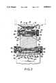
- FIG. 2is an elevational cross sectional view for showing the assembled state of the present invention
- FIG. 3is a fragmentary half cross sectional view for showing the inclining and swiveling portion of the present invention.
- FIG. 4is a schematic diagram for showing an example of height controlling state of the present invention.
- FIG. 1is an exploded perspective view of the present invention
- FIG. 2is an elevational cross sectional view showing assembled state of FIG. 1, wherein first knuckle means N1 is mounted at rear side of base 1.
- This first knuckle means N1is structured such that an arm 3 is rotatably fixed to two bosses 2a, 2a which are formed at both end sides of the rear portion of said base 1.
- Tapered holes 7a, 7a becoming narrower toward inside so as to be contacted in surface with tapered bushingsare formed at both sides of said boss 4a into which tapered bushings 6a, 6a are inserted respectively.
- Tapered pins 8a', 8a' of the knobs 8a, 8aare respectively inserted into the tapered bushings 6a, 6a, and with which tapered pins 8a', 8a' a screw bar 9a is in threaded engagement.
- tapered pins 8a', 8a'start to move along the threads of screw bar 9a inwardly or outwardly, and thus the moving of tapered pins 8a', 8a' cause the tapered bushings 6a, 6a to expand or contract, so that the surface contacting force with tapered hole 7a can be controlled.
- grooves 11a, 11a located at internally through holes 5a, 5a located at each boss 2a, 2a,can receive torsion springs 12a, 12a which react resiliently when receiving a torsional force.
- the above described identical structuresare provide respectively to right and left of the arm 3.
- a second knuckle means N2is provided at the top end of the arm 3.
- the structure of the second knuckle means N2is similar to that of the first knuckle means N1.
- a screw bar 9bis in threaded engagement with each knob 8b, 8b having the same function as knobs 8a, 8a, which are inserted through tapered bushings 6b, 6b and torsion springs 12b, 12b at grooves 11b, 11b into holes 5b, 5b of bosses 2b, 2b respectively, which the tapered bushings 6a, 6b are outwardly urged by a compression coil spring 10b.
- the semispherical body 14is structured to be able to turn by an angle of 360 degrees on the supporting plate 13.
- numeral 18represents an annular ring.
- Arm 3may be stopped at any desired position without turning by itself because knuckle N1 becomes fixed as a result of the friction force existing at the contact between the pins and the tapered bushings 6a, 6a.
- the semispherical body 14is slided within the range of the elongated hole 17, whereby it can be stopped at the desired position by closely contacting slider to the internal surface of semispherical body 14 and tightening the bolt 16.
- the semispherical body 14When it is desired to turn the display means M the semispherical body 14 is turned on the annular ring 18 of the supporting plate 13 whereby a swiveling motion of 360 degree angle becomes possible.
Landscapes
- Engineering & Computer Science (AREA)
- General Engineering & Computer Science (AREA)
- Mechanical Engineering (AREA)
- Devices For Indicating Variable Information By Combining Individual Elements (AREA)
- Pivots And Pivotal Connections (AREA)
Abstract
Description
The present invention relates to a supporting base for monitor, and more particularly, to a supporting base for controlling height, swivel and inclination of display means such as a monitor, television and terminal device (capable of controlling more conveniently).
Because the screen of display means may be exhibited differently it is important to be able to adjust the displayed information with the viewing direction and incident light from outside.
In order to provide such flexibility display means which swivel control the inclining angle have been proposed.
Korean utility model publication No. 85-2006, 2007, 2008, and Japanese utility model publication No. SHO-42821 also describe means of swiveling and controlling the display means.
However, since the display means supporting base of such system is only for inclination and swivel control device but height control means is not included, separate setting means is required at the time of adjusting the product, and if such adjustment is not made the user is not expected to be comfortable.
Further, because the inclination and swivel control device of said display means supporting base has a complicated structure, which is difficult to cast, a device which provides flexibility when viewing at a point that inclining angle and swiveling angle are limited within a predetermined extent, becomes a great improvement.
A device capable of controlling freely the height of the monitor and viewing angle of the screen is proposed in Korean utility model publication No. 85-1889.
According to this model a device is presented in which there is a recess having several hooking steps in circular arc on the top surface of the supporting base, and several supporting grooves are formed on the concave surface, and then a subsidiary supporting base is used in which a convex surface having several rectangular holes is formed on the upper portion of the subsidiary supporting base and several supporting, bars protrude downwardly to the bottom surface, such projections having cut out portions form a circular arc.
However, since this structure controls the height by setting another subsidiary supporting base on the main supporting base, there is a problem whenever the height control distance is limited to the height of subsidiary supporting base, and there is also a storage problem when the device is not used.
Therefore, the present invention is invented to solve several problems that the conventional display means supporting base has, and it is an object of the present invention to provide a supporting base for easily controlling the height, inclination and swivel of the display means.
In order to realize this, the present invention is characterized in that:
an arm is rotatably fixed to the base by knobs with tapered pins which are coupled to a screw bar in screwing manner from both sides thereof, wherein tapered pins are inserted through tapered bushings respectively, and when the knobs are moved along with said screw bar, the tapered bushings are both expanded and the inclination degree is maintained whereby the height can be controlled; and
inclining means similar to the height control system, are provided at the top end of an arm, on which swiveling control means formed by a semispherical body is provided.
The foregoing and other objects as well as advantages of the present invention will become clear the following description of the invention with reference to the accompanying drawings.
For a better understanding of the invention, and to show how the same may be carried out into effect, reference will now be made, by way of example, with respect to the accompanying drawings, in which:
FIG. 1 is an exploded perspective view of the present invention,
FIG. 2 is an elevational cross sectional view for showing the assembled state of the present invention,
FIG. 3 is a fragmentary half cross sectional view for showing the inclining and swiveling portion of the present invention, and
FIG. 4 is a schematic diagram for showing an example of height controlling state of the present invention.
Throughout the drawings, like reference numerals and symbols are used for designating like or equivalent parts or portions, for simplicity of illustration and explanation.
Hereinafter, a preferred embodiment of the present invention will be described in detail with reference to the accompanying drawings.
FIG. 1 is an exploded perspective view of the present invention, and FIG. 2 is an elevational cross sectional view showing assembled state of FIG. 1, wherein first knuckle means N1 is mounted at rear side ofbase 1.
This first knuckle means N1 is structured such that anarm 3 is rotatably fixed to twobosses said base 1.
And anotherboss 4a is formed at the bottom end ofarm 3, and each tip ends oftapered bushings holes boss 4a.
Taperedholes boss 4a into whichtapered bushings
Taperedpins 8a', 8a' of theknobs tapered bushings tapered pins 8a', 8a' a screw bar 9a is in threaded engagement.
Accordingly, when theknobs tapered pins 8a', 8a' start to move along the threads of screw bar 9a inwardly or outwardly, and thus the moving oftapered pins 8a', 8a' cause thetapered bushings tapered hole 7a can be controlled.
Whenknobs tapered pins 8a', 8a' move outwardly with the movement of thetapered bushings compression coil spring 10a contained within the interior ofboss 4a.
Further,grooves holes boss torsion springs arm 3.
On the other hand, a second knuckle means N2 is provided at the top end of thearm 3.
The structure of the second knuckle means N2 is similar to that of the first knuckle means N1.
That is, ascrew bar 9b is in threaded engagement with eachknob knobs tapered bushings torsion springs grooves holes tapered bushings
In addition, there is a supportingplate 13 with a spherical surface which is integrally formed and located on the top of boss 4b, to which asemispherical body 14 is coupled to the bottom of the display means M which is slidably mounted bybolt 16 throughslider 15.
Thesemispherical body 14 is structured to be able to turn by an angle of 360 degrees on the supportingplate 13.
In the drawing,numeral 18 represents an annular ring.
The operation of the present invention constituted as above will be described in detail as follows.
When theknobs tapered pins 8a', 8a' are moved along the screw bar 9a toward the center portion, and for this purpose, the knobs are turned in opposite directions manner of right and left to be oppositely of right turning screw coupling and left turning screw coupling.
Thetapered pins 8a', 8a' are inserted throughtapered bushings tapered holes
However, when theknobs tapered pins 8a', 8a' are moved outwardly, and thetapered bushings compression coil spring 10a whereby the close contact with thetapered holes
The release of the close contact by surface of thetapered bushings arm 3 and explains whyarm 3 can be made to stand or fold.
Therefore, when one desires to extend the height of the display means M then, thearm 3 can be made to stand as shown in FIG. 3.
The display means M can easily be lifted up as a result of the opposite resilient force exented bytorsion springs
Thus, when theknobs arm 3 can be made and fixed.
However, when thearm 3 is made to stand only by turning first knuckle means N1, since the display means M is inclined backwards, then theknobs plate 13 is made to stand and then theknobs
Whenever it is required to turn or incline the display means M in response to the amount and angle incident light and the display means M has to be pushed or pulled or turned, then it is possible to control the range of the inclining angle from -10 to +15 and the swivel angle of 360 degrees according to the operation as follow.
At first, with respect to the inclining control, when the display means M is pulled to the front or pushed to the back, thesemispherical body 14 is slided within the range of theelongated hole 17, whereby it can be stopped at the desired position by closely contacting slider to the internal surface ofsemispherical body 14 and tightening thebolt 16.
When it is desired to turn the display means M thesemispherical body 14 is turned on theannular ring 18 of the supportingplate 13 whereby a swiveling motion of 360 degree angle becomes possible.
Thus, according to the present invention, the screen of the display means can be adjusted according to the angle of incident light, quantity and directing angle and the height can be controlled in response to the eye level of the user, and thus is an advantage that efficiency of business can be enhanced.
It will be appreciated that the present invention is not restricted to the particular embodiment that has been described hereinbefore, and that variations and modifications may be made therein without departing from the spirit and scope of the invention as defined in the appended claims and equivalents thereof.
Claims (3)
1. A support for a display means so as to adjust the height, swivel and inclination thereof, said support comprising:
a base to be placed on a desk or the like, and having first boss means;
an elongated arm having second and third boss means, respectively at opposite ends of said arm;
a plate to be connected to the display means, and having fourth boss means;
first knuckle means rotatably connecting said second boss means at one end of said arm to said first boss means so that said arm is rotatable about a first axis substantially parallel to the desk; and second knuckle means rotatably connecting said third boss means at the other end of said arm to said fourth boss means so that said plate is rotatable about a second axis substantially parallel to said first axis;
wherein said second and fourth boss means each have tapered bores, said first and second knuckle means each including tapered bushings within said bores respectively; threaded bars respectively within said bores and threaded tapered pins respectively within said tapered bushings and threadedly engaging said threaded bars, whereby degree of rotation of said plate and arm are adjustable;
comprising torsion spring means interposed between said first and second boss means, and between said third and fourth boss means, respectively.
2. A support according to claim 1, wherein said first boss means is arranged at a rear portion of said base.
3. A support according to claim 1, comprising coil spring means between said tapered bushings.
Priority Applications (3)
| Application Number | Priority Date | Filing Date | Title |
|---|---|---|---|
| US07/443,520US4989813A (en) | 1989-11-29 | 1989-11-29 | Supporting base for controlling height, swivel and inclination of display means |
| DE3943137ADE3943137A1 (en) | 1989-11-29 | 1989-12-28 | CARRIER FOR ADJUSTING THE HEIGHT, SWIVELING ANGLE AND TILTING OF A DISPLAY DEVICE |
| GB9000235AGB2239594B (en) | 1989-11-29 | 1990-01-05 | A support |
Applications Claiming Priority (1)
| Application Number | Priority Date | Filing Date | Title |
|---|---|---|---|
| US07/443,520US4989813A (en) | 1989-11-29 | 1989-11-29 | Supporting base for controlling height, swivel and inclination of display means |
Publications (1)
| Publication Number | Publication Date |
|---|---|
| US4989813Atrue US4989813A (en) | 1991-02-05 |
Family
ID=23761115
Family Applications (1)
| Application Number | Title | Priority Date | Filing Date |
|---|---|---|---|
| US07/443,520Expired - LifetimeUS4989813A (en) | 1989-11-29 | 1989-11-29 | Supporting base for controlling height, swivel and inclination of display means |
Country Status (3)
| Country | Link |
|---|---|
| US (1) | US4989813A (en) |
| DE (1) | DE3943137A1 (en) |
| GB (1) | GB2239594B (en) |
Cited By (79)
| Publication number | Priority date | Publication date | Assignee | Title |
|---|---|---|---|---|
| US5173837A (en)* | 1990-10-15 | 1992-12-22 | Compaq Computer Corporation | Hinge with two-towed clutch spring for suppressing electromagnetic interference for laptop personal computers |
| FR2704043A1 (en)* | 1993-04-16 | 1994-10-21 | Alcatel Business Systems | Method and device for positioning a detection station of a tracking system |
| EP0722064A1 (en)* | 1995-01-12 | 1996-07-17 | NCR International, Inc. | A mounting apparatus |
| US5553820A (en)* | 1994-10-17 | 1996-09-10 | Rubbermaid Office Products Inc. | Adjustable monitor arm |
| US5564668A (en)* | 1995-02-15 | 1996-10-15 | Crowe, Ii; Marvin E. | Computer stand for vehicles |
| USD383739S (en)* | 1996-05-06 | 1997-09-16 | KS-Design GmbH | Computer monitor |
| US5842672A (en)* | 1996-06-07 | 1998-12-01 | Ergotron, Inc. | Mounting system for flat panel display, keyboard and stand |
| US5857415A (en)* | 1993-08-24 | 1999-01-12 | Richard; Paul E. | Ergonomic computer workstation and method of using |
| US5887837A (en)* | 1996-09-30 | 1999-03-30 | Johns; H. Douglas | Pivotal computer stand |
| US6047939A (en)* | 1997-07-09 | 2000-04-11 | Lg Electronics Inc. | Adjustable support structure for video appliance |
| US6050535A (en)* | 1997-12-31 | 2000-04-18 | Samsung Electronics Co., Ltd. | Flat panel display device having a wide adjusting range of a visual angle |
| US6276655B1 (en)* | 1997-12-12 | 2001-08-21 | Samsung Electronics Co., Ltd. | Flat panel display device |
| US20010017761A1 (en)* | 1993-06-29 | 2001-08-30 | Ditzik Richard J. | Desktop device with adjustable flat panel screen |
| US6464185B1 (en)* | 1998-11-16 | 2002-10-15 | Garmin Corporation | Multi-position articulating mounting apparatus for an electronic device |
| US20030030620A1 (en)* | 2001-08-08 | 2003-02-13 | International Business Machines Corporation | Adjustable display device |
| US20030086240A1 (en)* | 2001-11-08 | 2003-05-08 | Jobs Steven P | Computer controlled display device |
| US20030173476A1 (en)* | 2002-03-12 | 2003-09-18 | Kuni Masuda | Stable support system for displays |
| US20030223188A1 (en)* | 2002-05-28 | 2003-12-04 | Samsung Electronics Co., Ltd. | Tilting apparatus of monitor |
| US6663064B1 (en) | 1999-12-01 | 2003-12-16 | Garmin Corporation | Multi-position articulating mounting apparatus for an electronic device |
| US20040004165A1 (en)* | 2002-07-06 | 2004-01-08 | Samsung Electronics Co., Ltd. | Display apparatus |
| US20040012917A1 (en)* | 2002-07-16 | 2004-01-22 | Samsung Electronics Co., Ltd. | Monitor improved in a tilting structure |
| USD486486S1 (en) | 2001-11-08 | 2004-02-10 | Apple Computer, Inc. | Display device with a moveable assembly |
| US20040051012A1 (en)* | 1999-12-14 | 2004-03-18 | Fujitsu Limited | Tilt-swivel stand |
| USD487893S1 (en) | 2001-11-08 | 2004-03-30 | Apple Computer, Inc. | Display device with a moveable assembly |
| USD489370S1 (en) | 2001-11-08 | 2004-05-04 | Apple Computer, Inc. | Display device with a moveable assembly |
| US20040084579A1 (en)* | 2002-10-30 | 2004-05-06 | Samsung Electronics Co., Ltd. | Stand for display |
| US20040084578A1 (en)* | 2002-11-05 | 2004-05-06 | Samsung Electronics, Co., Ltd. | Display apparatus |
| US6734922B1 (en)* | 1999-10-08 | 2004-05-11 | Lg Electronics Inc. | Base assembly for video display appliance |
| US20040118984A1 (en)* | 2002-09-27 | 2004-06-24 | Samsung Electronics Co., Ltd. | Display apparatus |
| US20040147178A1 (en)* | 2002-11-11 | 2004-07-29 | Samsung Electronics Co., Ltd. | Monitor |
| US20040159757A1 (en)* | 2003-01-09 | 2004-08-19 | Decade Industries, Inc. D/B/A Sanus Systems | Articulated mount |
| US20040211866A1 (en)* | 2001-11-19 | 2004-10-28 | Samsung Electronics Co., Ltd. | Monitor improved in a tilting and combining structure |
| US20040218352A1 (en)* | 2001-11-08 | 2004-11-04 | Hillman Michael D. | Computer controlled display device |
| US20040228080A1 (en)* | 2001-11-08 | 2004-11-18 | Hillman Michael D. | Computer controlled display device |
| US20040231213A1 (en)* | 2003-05-23 | 2004-11-25 | Samsung Electronic Co., Ltd. | Display apparatus |
| US20040257755A1 (en)* | 2001-11-08 | 2004-12-23 | Hillman Michael D. | Computer controlled display device |
| US20050002159A1 (en)* | 2002-09-28 | 2005-01-06 | Samsung Electronics Co., Ltd. | Monitor |
| US20050015939A1 (en)* | 2002-04-12 | 2005-01-27 | Gijsel Geert Van | Suspension system |
| US20050029424A1 (en)* | 2003-08-06 | 2005-02-10 | Liu Alvin (Chien-Chung) | Adjusting assembly for LCD monitor |
| US20050097706A1 (en)* | 2003-11-12 | 2005-05-12 | Toshiba International Corporation | Incremental locking hinge assembly |
| US20050133678A1 (en)* | 2002-06-11 | 2005-06-23 | Chief Manufacturing Inc. | Adjustable, self-balancing flat panel display mounting system |
| US20050145759A1 (en)* | 2004-01-06 | 2005-07-07 | Albert Shih | Display apparatus with adjustable supporting device |
| US6929224B1 (en) | 2002-03-12 | 2005-08-16 | Sun Microsystems, Inc. | Multi-hinge system for displays |
| USD509826S1 (en)* | 2001-11-08 | 2005-09-20 | Apple Computer, Inc. | Display device with a moveable assembly |
| USD510088S1 (en)* | 2001-11-08 | 2005-09-27 | Apple Computer, Inc. | Display device with a moveable assembly |
| USD510577S1 (en)* | 2001-11-08 | 2005-10-11 | Apple Computer, Inc. | Display device with a moveable assembly |
| US20060022102A1 (en)* | 2003-05-30 | 2006-02-02 | Jay Dittmer | Self-balancing adjustable mounting system with friction adjustment |
| US20060058941A1 (en)* | 1999-04-19 | 2006-03-16 | Dekock Bruce W | System for providing traffic information |
| US7028961B1 (en)* | 2003-05-30 | 2006-04-18 | Csav, Inc. | Self-balancing adjustable flat panel mounting system |
| US20060176655A1 (en)* | 2001-11-08 | 2006-08-10 | Hillman Michael D | Computer controlled display device |
| US20060181637A1 (en)* | 2005-02-16 | 2006-08-17 | Innovative Office Products, Inc. | Quick release assembly for an electronic device |
| US20060214082A1 (en)* | 2005-03-22 | 2006-09-28 | Trace Benjamin M | Folding stand for a portable crimping device |
| US20060255216A1 (en)* | 2004-05-06 | 2006-11-16 | Lg Electronics Inc. | Stand assembly for monitor |
| US20070040084A1 (en)* | 2005-06-03 | 2007-02-22 | Lane Sturman | Support arm assembly |
| US20070080270A1 (en)* | 2005-10-06 | 2007-04-12 | Lg Electronics Inc. | Stand for image display device |
| US20070152114A1 (en)* | 2005-12-30 | 2007-07-05 | Lg Electronics Inc. | Stand for display device |
| US20070153459A1 (en)* | 2006-01-04 | 2007-07-05 | Jim Wohlford | Mounting system for flat panel electronic display |
| US20070194196A1 (en)* | 2003-01-09 | 2007-08-23 | Csav, Inc. | Adjustable tilt mount |
| US20070201197A1 (en)* | 2001-11-08 | 2007-08-30 | Hillman Michael D | Computer controlled display device |
| US20080037207A1 (en)* | 2006-08-09 | 2008-02-14 | Ting-Hui Chih | Support structure for supporting an object |
| US7380759B1 (en) | 1998-11-16 | 2008-06-03 | Garmin Corporation | Multi-position articulating mounting apparatus for an electronic device |
| US7389963B2 (en) | 2002-08-24 | 2008-06-24 | Samsung Electronics Co., Ltd. | Display apparatus |
| US20080278044A1 (en)* | 2006-01-24 | 2008-11-13 | Fujitsu Limited | Display support apparatus |
| US20090050763A1 (en)* | 2007-01-05 | 2009-02-26 | Jay Dittmer | In-wall mount |
| USD595723S1 (en) | 2007-11-09 | 2009-07-07 | Milestone Av Technologies Llc | Pivot arm assembly for mounting an electronic display |
| US20100149736A1 (en)* | 2007-01-05 | 2010-06-17 | Jay Dittmer | Wall-avoiding self-balancing mount for tilt positioning of a flat panel electronic display |
| US20100172073A1 (en)* | 2009-01-06 | 2010-07-08 | Innocom Technology (Shenzhen) Co., Ltd. | Flat panel display with support providing pivoting |
| USD620943S1 (en) | 2009-01-07 | 2010-08-03 | Milestone Av Technologies Llc | Single arm display mount |
| US20100239130A1 (en)* | 2009-03-18 | 2010-09-23 | Industrial Technology Research Institute | System and method for performing rapid facial recognition |
| USD627787S1 (en) | 2009-01-07 | 2010-11-23 | Milestone Av Technologies Llc | Display mount with single articulating arm |
| US7908080B2 (en) | 2004-12-31 | 2011-03-15 | Google Inc. | Transportation routing |
| US20110234926A1 (en)* | 2008-09-02 | 2011-09-29 | Milestone Av Technologies Llc | Low profile mount for flat panel electronic display |
| US8072739B2 (en) | 2007-01-03 | 2011-12-06 | Milestone Av Technologies Llc | Device mount with selectively positionable tilt axis |
| USD684982S1 (en) | 2010-08-11 | 2013-06-25 | Colebrook Bosson Saunders (Products) Limited | Display support with indicator window |
| US8756842B2 (en)* | 2000-10-06 | 2014-06-24 | Clamp Swing Pricing Company | Sign holder device |
| US8763976B1 (en)* | 2012-01-18 | 2014-07-01 | Arctic, LLC | Mounting accessory for personal electronics |
| US8891249B2 (en) | 2009-01-07 | 2014-11-18 | Milestone Av Technologies Llc | Display mount with adjustable position tilt axis |
| US9074721B2 (en) | 2010-06-09 | 2015-07-07 | Alex Lau | Support system |
| US9316346B2 (en) | 2010-06-09 | 2016-04-19 | Colebrook Bosson Saunders (Products) Limited | Support system |
Families Citing this family (3)
| Publication number | Priority date | Publication date | Assignee | Title |
|---|---|---|---|---|
| DE4214341A1 (en)* | 1992-05-09 | 1993-11-11 | Ivan Mallinowski | Computer housing with adjustable monitor and keyboard holders - has computer mounted on plinth and supports spherically dished mounting plate on two adjustable pillars |
| EP1344972A3 (en)* | 2002-03-12 | 2004-12-08 | Sun Microsystems, Inc. | Systems for supporting displays |
| CN105299415B (en)* | 2015-11-13 | 2017-08-25 | 中山市宜高机电科技有限公司 | Multi-joint liquid crystal display television suspension bracket |
Citations (12)
| Publication number | Priority date | Publication date | Assignee | Title |
|---|---|---|---|---|
| GB746329A (en)* | 1953-11-09 | 1956-03-14 | Wheaton Brass Works | Improvements in spring counterbalanced swing-joint-supported conduit |
| US3123330A (en)* | 1964-03-03 | Forbes-robinson | ||
| US4068961A (en)* | 1976-08-23 | 1978-01-17 | Milgo Electronic Corporation | Swivel joint |
| US4554590A (en)* | 1980-06-05 | 1985-11-19 | Ing. C. Olivetti & C., S.P.A. | Device for positioning video display unit |
| US4562988A (en)* | 1984-06-27 | 1986-01-07 | Northern Telecom Limited | Video display mounting mechanism providing pivoting and tilting of the display |
| US4591123A (en)* | 1981-07-20 | 1986-05-27 | International Business Machines Corporation | Adjustable brake assembly |
| US4645153A (en)* | 1985-05-23 | 1987-02-24 | Ncr Corporation | Tilt and swivel support |
| US4691886A (en)* | 1985-04-18 | 1987-09-08 | Texas Instruments Incorporated | Adjustable display stand |
| US4729533A (en)* | 1986-04-19 | 1988-03-08 | International Business Machines Corporation | Support apparatus |
| US4834329A (en)* | 1987-05-29 | 1989-05-30 | Michael Delapp | Monitor support for a terminal |
| US4852500A (en)* | 1987-03-18 | 1989-08-01 | Herman Miller, Inc. | Integrated computer implement work area |
| US4880191A (en)* | 1984-07-05 | 1989-11-14 | Unisys Corporation | Mounting arrangement for display terminal |
Family Cites Families (7)
| Publication number | Priority date | Publication date | Assignee | Title |
|---|---|---|---|---|
| DE2847135C3 (en)* | 1978-10-30 | 1985-01-10 | Nixdorf Computer Ag, 4790 Paderborn | Stand for an information display unit having a box-shaped housing |
| DE3031463A1 (en)* | 1980-08-20 | 1982-03-25 | Siemens AG, 1000 Berlin und 8000 München | DEVICE FOR SETTING UP A VIEWING DEVICE ON A WORKTOP |
| DE3036852C2 (en)* | 1980-09-30 | 1984-02-23 | Tandberg Data A/S, Oslo | Device for setting up a data display device on a work surface |
| DE3105601A1 (en)* | 1981-02-16 | 1982-09-02 | Siemens AG, 1000 Berlin und 8000 München | DATA VISION DEVICE |
| DE3390529T1 (en)* | 1983-10-11 | 1986-01-09 | Tektronix, Inc., Beaverton, Oreg. | Base for computer monitors |
| US4624434A (en)* | 1984-12-19 | 1986-11-25 | Burroughs Corporation | Stable tiltable display terminal |
| GB2222939A (en)* | 1988-08-19 | 1990-03-28 | Microcomputer Accessories Inc | Adjustable CRT support stand |
- 1989
- 1989-11-29USUS07/443,520patent/US4989813A/ennot_activeExpired - Lifetime
- 1989-12-28DEDE3943137Apatent/DE3943137A1/ennot_activeWithdrawn
- 1990
- 1990-01-05GBGB9000235Apatent/GB2239594B/ennot_activeExpired - Fee Related
Patent Citations (12)
| Publication number | Priority date | Publication date | Assignee | Title |
|---|---|---|---|---|
| US3123330A (en)* | 1964-03-03 | Forbes-robinson | ||
| GB746329A (en)* | 1953-11-09 | 1956-03-14 | Wheaton Brass Works | Improvements in spring counterbalanced swing-joint-supported conduit |
| US4068961A (en)* | 1976-08-23 | 1978-01-17 | Milgo Electronic Corporation | Swivel joint |
| US4554590A (en)* | 1980-06-05 | 1985-11-19 | Ing. C. Olivetti & C., S.P.A. | Device for positioning video display unit |
| US4591123A (en)* | 1981-07-20 | 1986-05-27 | International Business Machines Corporation | Adjustable brake assembly |
| US4562988A (en)* | 1984-06-27 | 1986-01-07 | Northern Telecom Limited | Video display mounting mechanism providing pivoting and tilting of the display |
| US4880191A (en)* | 1984-07-05 | 1989-11-14 | Unisys Corporation | Mounting arrangement for display terminal |
| US4691886A (en)* | 1985-04-18 | 1987-09-08 | Texas Instruments Incorporated | Adjustable display stand |
| US4645153A (en)* | 1985-05-23 | 1987-02-24 | Ncr Corporation | Tilt and swivel support |
| US4729533A (en)* | 1986-04-19 | 1988-03-08 | International Business Machines Corporation | Support apparatus |
| US4852500A (en)* | 1987-03-18 | 1989-08-01 | Herman Miller, Inc. | Integrated computer implement work area |
| US4834329A (en)* | 1987-05-29 | 1989-05-30 | Michael Delapp | Monitor support for a terminal |
Cited By (159)
| Publication number | Priority date | Publication date | Assignee | Title |
|---|---|---|---|---|
| US5173837A (en)* | 1990-10-15 | 1992-12-22 | Compaq Computer Corporation | Hinge with two-towed clutch spring for suppressing electromagnetic interference for laptop personal computers |
| FR2704043A1 (en)* | 1993-04-16 | 1994-10-21 | Alcatel Business Systems | Method and device for positioning a detection station of a tracking system |
| US20060187626A1 (en)* | 1993-06-29 | 2006-08-24 | Ditzik Richard J | Desktop device with adjustable flat screen display |
| US7091961B2 (en)* | 1993-06-29 | 2006-08-15 | Ditzik Richard J | Desktop device with adjustable flat screen display |
| US20030080949A1 (en)* | 1993-06-29 | 2003-05-01 | Ditzik Richard J. | Desktop device with adjustable flat screen display |
| US20010017761A1 (en)* | 1993-06-29 | 2001-08-30 | Ditzik Richard J. | Desktop device with adjustable flat panel screen |
| US6326955B1 (en)* | 1993-06-29 | 2001-12-04 | Richard J. Ditzik | Information device with adjustable flat panel screen |
| US5857415A (en)* | 1993-08-24 | 1999-01-12 | Richard; Paul E. | Ergonomic computer workstation and method of using |
| US5553820A (en)* | 1994-10-17 | 1996-09-10 | Rubbermaid Office Products Inc. | Adjustable monitor arm |
| US5593119A (en)* | 1995-01-12 | 1997-01-14 | At&T Global Information Solutions Company | Apparatus and method for mounting a terminal |
| EP0722064A1 (en)* | 1995-01-12 | 1996-07-17 | NCR International, Inc. | A mounting apparatus |
| US5564668A (en)* | 1995-02-15 | 1996-10-15 | Crowe, Ii; Marvin E. | Computer stand for vehicles |
| USD383739S (en)* | 1996-05-06 | 1997-09-16 | KS-Design GmbH | Computer monitor |
| US5924665A (en)* | 1996-06-07 | 1999-07-20 | Ergotron, Inc. | Ceiling system for a flat panel display |
| US6015120A (en)* | 1996-06-07 | 2000-01-18 | Ergotron, Inc. | Desktop flat panel display support system |
| US6019332A (en)* | 1996-06-07 | 2000-02-01 | Ergotron, Inc. | Pivot/ratchet assembly and support system |
| US5992809A (en)* | 1996-06-07 | 1999-11-30 | Ergotron, Inc. | Mounting system for flat panel display, keyboard, and stand |
| US5967479A (en)* | 1996-06-07 | 1999-10-19 | Ergotron, Inc. | Keyboard tray on support arm with pivoting brake |
| US5947429A (en)* | 1996-06-07 | 1999-09-07 | Ergotron, Inc. | Table mount system for flat panel display |
| US5842672A (en)* | 1996-06-07 | 1998-12-01 | Ergotron, Inc. | Mounting system for flat panel display, keyboard and stand |
| US5887837A (en)* | 1996-09-30 | 1999-03-30 | Johns; H. Douglas | Pivotal computer stand |
| US6047939A (en)* | 1997-07-09 | 2000-04-11 | Lg Electronics Inc. | Adjustable support structure for video appliance |
| US6276655B1 (en)* | 1997-12-12 | 2001-08-21 | Samsung Electronics Co., Ltd. | Flat panel display device |
| US6050535A (en)* | 1997-12-31 | 2000-04-18 | Samsung Electronics Co., Ltd. | Flat panel display device having a wide adjusting range of a visual angle |
| US6464185B1 (en)* | 1998-11-16 | 2002-10-15 | Garmin Corporation | Multi-position articulating mounting apparatus for an electronic device |
| US7380759B1 (en) | 1998-11-16 | 2008-06-03 | Garmin Corporation | Multi-position articulating mounting apparatus for an electronic device |
| US20060058941A1 (en)* | 1999-04-19 | 2006-03-16 | Dekock Bruce W | System for providing traffic information |
| US6734922B1 (en)* | 1999-10-08 | 2004-05-11 | Lg Electronics Inc. | Base assembly for video display appliance |
| US6663064B1 (en) | 1999-12-01 | 2003-12-16 | Garmin Corporation | Multi-position articulating mounting apparatus for an electronic device |
| US6869056B2 (en)* | 1999-12-14 | 2005-03-22 | Fujitsu Limited | Tilt-swivel stand |
| US20040051012A1 (en)* | 1999-12-14 | 2004-03-18 | Fujitsu Limited | Tilt-swivel stand |
| US8756842B2 (en)* | 2000-10-06 | 2014-06-24 | Clamp Swing Pricing Company | Sign holder device |
| US20030030620A1 (en)* | 2001-08-08 | 2003-02-13 | International Business Machines Corporation | Adjustable display device |
| USD496040S1 (en) | 2001-11-08 | 2004-09-14 | Apple Computer, Inc. | Display device with a moveable assembly |
| USD510088S1 (en)* | 2001-11-08 | 2005-09-27 | Apple Computer, Inc. | Display device with a moveable assembly |
| US20070201197A1 (en)* | 2001-11-08 | 2007-08-30 | Hillman Michael D | Computer controlled display device |
| USD489370S1 (en) | 2001-11-08 | 2004-05-04 | Apple Computer, Inc. | Display device with a moveable assembly |
| US7349203B2 (en) | 2001-11-08 | 2008-03-25 | Apple Inc. | Computer controlled display device |
| US20030086240A1 (en)* | 2001-11-08 | 2003-05-08 | Jobs Steven P | Computer controlled display device |
| USD487893S1 (en) | 2001-11-08 | 2004-03-30 | Apple Computer, Inc. | Display device with a moveable assembly |
| USD494971S1 (en) | 2001-11-08 | 2004-08-24 | Apple Computer, Inc. | Display device with a moveable assembly |
| USD495332S1 (en) | 2001-11-08 | 2004-08-31 | Apple Computer, Inc. | Display device with a moveable assembly |
| US20070014084A1 (en)* | 2001-11-08 | 2007-01-18 | Jobs Steven P | Computer controlled display device |
| US7136280B2 (en) | 2001-11-08 | 2006-11-14 | Apple Computer, Inc. | Computer controlled display device |
| US20040218352A1 (en)* | 2001-11-08 | 2004-11-04 | Hillman Michael D. | Computer controlled display device |
| US6819550B2 (en) | 2001-11-08 | 2004-11-16 | Apple Computer, Inc. | Computer controlled display device |
| US20040228080A1 (en)* | 2001-11-08 | 2004-11-18 | Hillman Michael D. | Computer controlled display device |
| US20060176655A1 (en)* | 2001-11-08 | 2006-08-10 | Hillman Michael D | Computer controlled display device |
| US20040257755A1 (en)* | 2001-11-08 | 2004-12-23 | Hillman Michael D. | Computer controlled display device |
| USD510577S1 (en)* | 2001-11-08 | 2005-10-11 | Apple Computer, Inc. | Display device with a moveable assembly |
| USD509826S1 (en)* | 2001-11-08 | 2005-09-20 | Apple Computer, Inc. | Display device with a moveable assembly |
| US7773371B2 (en) | 2001-11-08 | 2010-08-10 | Apple Inc. | Computer controlled display device |
| US20050088814A1 (en)* | 2001-11-08 | 2005-04-28 | Jobs Steven P. | Computer controlled display device |
| USD486486S1 (en) | 2001-11-08 | 2004-02-10 | Apple Computer, Inc. | Display device with a moveable assembly |
| US7513468B2 (en) | 2001-11-19 | 2009-04-07 | Samsung Electronics Co., Ltd. | Monitor improved in a tilting and combining structure |
| US7819368B2 (en) | 2001-11-19 | 2010-10-26 | Samsung Electronics Co., Ltd. | Monitor improved in a tilting and combining structure |
| US20050006537A1 (en)* | 2001-11-19 | 2005-01-13 | Samsung Electronics Co., Ltd. | Monitor improved in a tilting and combining structure |
| US20040211866A1 (en)* | 2001-11-19 | 2004-10-28 | Samsung Electronics Co., Ltd. | Monitor improved in a tilting and combining structure |
| US7604206B2 (en)* | 2001-11-19 | 2009-10-20 | Samsung Electronics Co., Ltd. | Monitor improved in a tilting and combining structure |
| US20030173476A1 (en)* | 2002-03-12 | 2003-09-18 | Kuni Masuda | Stable support system for displays |
| US6929224B1 (en) | 2002-03-12 | 2005-08-16 | Sun Microsystems, Inc. | Multi-hinge system for displays |
| US20050015939A1 (en)* | 2002-04-12 | 2005-01-27 | Gijsel Geert Van | Suspension system |
| US7177144B2 (en) | 2002-05-28 | 2007-02-13 | Samsung Electronics Co., Ltd. | Tilting apparatus of monitor |
| US20030223188A1 (en)* | 2002-05-28 | 2003-12-04 | Samsung Electronics Co., Ltd. | Tilting apparatus of monitor |
| US20090020673A1 (en)* | 2002-06-11 | 2009-01-22 | Jay Dittmer | Adjustable, self-balancing flat panel display mounting system |
| US7954780B2 (en) | 2002-06-11 | 2011-06-07 | Milestone Av Technologies Llc | Adjustable self-balancing flat panel display mounting system |
| US8490934B2 (en) | 2002-06-11 | 2013-07-23 | Milestone Av Technologies Llc | Adjustable, self-balancing flat panel display mounting system |
| US20050133678A1 (en)* | 2002-06-11 | 2005-06-23 | Chief Manufacturing Inc. | Adjustable, self-balancing flat panel display mounting system |
| US20070181762A1 (en)* | 2002-06-11 | 2007-08-09 | Jay Dittmer | Adjustable self-balancing flat panel display mounting system |
| US7395996B2 (en) | 2002-06-11 | 2008-07-08 | Csav, Inc. | Adjustable, self-balancing flat panel display mounting system |
| US7168665B2 (en) | 2002-07-06 | 2007-01-30 | Samsung Electronics Co., Ltd. | Display apparatus |
| US20040004165A1 (en)* | 2002-07-06 | 2004-01-08 | Samsung Electronics Co., Ltd. | Display apparatus |
| US20040012917A1 (en)* | 2002-07-16 | 2004-01-22 | Samsung Electronics Co., Ltd. | Monitor improved in a tilting structure |
| US7389963B2 (en) | 2002-08-24 | 2008-06-24 | Samsung Electronics Co., Ltd. | Display apparatus |
| US7424991B2 (en) | 2002-09-27 | 2008-09-16 | Samsung Electronics Co., Ltd. | Display apparatus |
| US20040118984A1 (en)* | 2002-09-27 | 2004-06-24 | Samsung Electronics Co., Ltd. | Display apparatus |
| US7567436B2 (en) | 2002-09-28 | 2009-07-28 | Samsung Electronics Co., Ltd. | Monitor |
| US20050002159A1 (en)* | 2002-09-28 | 2005-01-06 | Samsung Electronics Co., Ltd. | Monitor |
| US20040084579A1 (en)* | 2002-10-30 | 2004-05-06 | Samsung Electronics Co., Ltd. | Stand for display |
| US7195214B2 (en) | 2002-10-30 | 2007-03-27 | Samsung Electronics Co., Ltd. | Stand for display |
| US7237755B2 (en) | 2002-11-05 | 2007-07-03 | Samsung Electronics Co., Ltd. | Display apparatus |
| US20040084578A1 (en)* | 2002-11-05 | 2004-05-06 | Samsung Electronics, Co., Ltd. | Display apparatus |
| US7573711B2 (en) | 2002-11-11 | 2009-08-11 | Samsung Electronics Co., Ltd. | Monitor having a moving member counterbalancing weight of display |
| US20040147178A1 (en)* | 2002-11-11 | 2004-07-29 | Samsung Electronics Co., Ltd. | Monitor |
| US20070284488A1 (en)* | 2002-11-11 | 2007-12-13 | Samsung Electronics Co., Ltd. | Monitor |
| US7274555B2 (en) | 2002-11-11 | 2007-09-25 | Samsung Electronics Co., Ltd. | Stand for supporting a monitor main body |
| EP1610653A4 (en)* | 2003-01-09 | 2007-04-04 | Decade Ind Inc D B A Sanus Sys | Articulated mount |
| US7438269B2 (en) | 2003-01-09 | 2008-10-21 | Csav, Inc. | Adjustable tilt mount |
| US7243892B2 (en) | 2003-01-09 | 2007-07-17 | Csav, Inc. | Articulated mount |
| US20040159757A1 (en)* | 2003-01-09 | 2004-08-19 | Decade Industries, Inc. D/B/A Sanus Systems | Articulated mount |
| US8235342B2 (en) | 2003-01-09 | 2012-08-07 | Milestone AV Techonologies LLC | Adjustable tilt mount |
| US20090084918A1 (en)* | 2003-01-09 | 2009-04-02 | Pfister Joel W | Adjustable tilt mount |
| US20070194196A1 (en)* | 2003-01-09 | 2007-08-23 | Csav, Inc. | Adjustable tilt mount |
| US20040231213A1 (en)* | 2003-05-23 | 2004-11-25 | Samsung Electronic Co., Ltd. | Display apparatus |
| US7611103B2 (en)* | 2003-05-23 | 2009-11-03 | Samsung Electronics Co., Ltd. | Display apparatus |
| US9279536B2 (en) | 2003-05-30 | 2016-03-08 | Milestone Av Technologies Llc | Self-balancing adjustable flat panel mounting system |
| US20100214729A1 (en)* | 2003-05-30 | 2010-08-26 | Jay Dittmer | Self-balancing adjustable flat panel mounting system |
| US7823849B2 (en) | 2003-05-30 | 2010-11-02 | Milestone Av Technologies Llc | Self-balancing adjustable flat panel mounting system |
| US7380760B2 (en) | 2003-05-30 | 2008-06-03 | Csav, Inc. | Self-balancing adjustable mounting system with friction adjustment |
| US7387286B2 (en) | 2003-05-30 | 2008-06-17 | Csav, Inc. | Self-balancing adjustable flat panel mounting system |
| US20080117580A1 (en)* | 2003-05-30 | 2008-05-22 | Jay Dittmer | Self-balancing adjustable flat panel mounting system |
| US20060022102A1 (en)* | 2003-05-30 | 2006-02-02 | Jay Dittmer | Self-balancing adjustable mounting system with friction adjustment |
| US7028961B1 (en)* | 2003-05-30 | 2006-04-18 | Csav, Inc. | Self-balancing adjustable flat panel mounting system |
| US20060186295A1 (en)* | 2003-05-30 | 2006-08-24 | Chief Manufacturing Inc. | Self-balancing adjustable flat panel mounting system |
| US20050029424A1 (en)* | 2003-08-06 | 2005-02-10 | Liu Alvin (Chien-Chung) | Adjusting assembly for LCD monitor |
| US7338019B2 (en)* | 2003-08-06 | 2008-03-04 | Hon Hai Precision Ind. Co., Ltd. | Adjusting assembly for LCD monitor |
| US20070214603A1 (en)* | 2003-11-12 | 2007-09-20 | Toshiba International Corporation | Incremental Locking Hinge Assembly |
| US20050097706A1 (en)* | 2003-11-12 | 2005-05-12 | Toshiba International Corporation | Incremental locking hinge assembly |
| US7665185B2 (en) | 2003-11-12 | 2010-02-23 | Toshiba International Corporation | Incremental locking hinge assembly |
| US7222395B2 (en)* | 2003-11-12 | 2007-05-29 | Toshiba International Corporation | Incremental locking hinge assembly |
| US6962312B2 (en)* | 2004-01-06 | 2005-11-08 | Amtran Technology Co., Ltd. | Display apparatus with adjustable supporting device |
| US20050145759A1 (en)* | 2004-01-06 | 2005-07-07 | Albert Shih | Display apparatus with adjustable supporting device |
| US20060255216A1 (en)* | 2004-05-06 | 2006-11-16 | Lg Electronics Inc. | Stand assembly for monitor |
| US7651058B2 (en)* | 2004-05-06 | 2010-01-26 | Lg Electronics Inc. | Stand assembly for monitor |
| US9709415B2 (en) | 2004-12-31 | 2017-07-18 | Google Inc. | Transportation routing |
| US7908080B2 (en) | 2004-12-31 | 2011-03-15 | Google Inc. | Transportation routing |
| US9945686B2 (en) | 2004-12-31 | 2018-04-17 | Google Llc | Transportation routing |
| US11092455B2 (en) | 2004-12-31 | 2021-08-17 | Google Llc | Transportation routing |
| US9778055B2 (en) | 2004-12-31 | 2017-10-03 | Google Inc. | Transportation routing |
| US8606514B2 (en) | 2004-12-31 | 2013-12-10 | Google Inc. | Transportation routing |
| US8798917B2 (en) | 2004-12-31 | 2014-08-05 | Google Inc. | Transportation routing |
| US20060181637A1 (en)* | 2005-02-16 | 2006-08-17 | Innovative Office Products, Inc. | Quick release assembly for an electronic device |
| US7673838B2 (en) | 2005-02-16 | 2010-03-09 | Innovative Office Products, Inc. | Quick release assembly for an electronic device |
| US20060214082A1 (en)* | 2005-03-22 | 2006-09-28 | Trace Benjamin M | Folding stand for a portable crimping device |
| US7360304B2 (en) | 2005-03-22 | 2008-04-22 | Parker-Hannifin Corporation | Folding stand for a portable crimping device |
| US8794579B2 (en) | 2005-06-03 | 2014-08-05 | Steelcase, Inc. | Support arm assembly |
| US20070040084A1 (en)* | 2005-06-03 | 2007-02-22 | Lane Sturman | Support arm assembly |
| US20070080270A1 (en)* | 2005-10-06 | 2007-04-12 | Lg Electronics Inc. | Stand for image display device |
| US7681848B2 (en)* | 2005-10-06 | 2010-03-23 | Lg Electronics Inc. | Stand for image display device |
| US20070152114A1 (en)* | 2005-12-30 | 2007-07-05 | Lg Electronics Inc. | Stand for display device |
| US7748680B2 (en)* | 2005-12-30 | 2010-07-06 | Lg Electronics Inc. | Foldable stand for display device |
| US20070153459A1 (en)* | 2006-01-04 | 2007-07-05 | Jim Wohlford | Mounting system for flat panel electronic display |
| US20080278044A1 (en)* | 2006-01-24 | 2008-11-13 | Fujitsu Limited | Display support apparatus |
| US8081261B2 (en)* | 2006-01-24 | 2011-12-20 | Fujitsu Limited | Display support apparatus |
| US20080037207A1 (en)* | 2006-08-09 | 2008-02-14 | Ting-Hui Chih | Support structure for supporting an object |
| US8072739B2 (en) | 2007-01-03 | 2011-12-06 | Milestone Av Technologies Llc | Device mount with selectively positionable tilt axis |
| US8094438B2 (en) | 2007-01-05 | 2012-01-10 | Milestone Av Technologies Llc | Wall-avoiding self-balancing mount for tilt positioning of a flat panel electronic display |
| US20090050763A1 (en)* | 2007-01-05 | 2009-02-26 | Jay Dittmer | In-wall mount |
| US20100149736A1 (en)* | 2007-01-05 | 2010-06-17 | Jay Dittmer | Wall-avoiding self-balancing mount for tilt positioning of a flat panel electronic display |
| US7866622B2 (en) | 2007-01-05 | 2011-01-11 | Milestone Av Technologies Llc | In-wall mount |
| US8508918B2 (en) | 2007-01-05 | 2013-08-13 | Milestone Av Technologies Llc | Wall-avoiding self-balancing mount for tilt positioning of a flat panel electronic display |
| US20100294904A1 (en)* | 2007-01-05 | 2010-11-25 | Csav, Inc. | Wall-avoiding self-balancing mount for tilt positioning of a flat panel electronic display |
| USD595723S1 (en) | 2007-11-09 | 2009-07-07 | Milestone Av Technologies Llc | Pivot arm assembly for mounting an electronic display |
| US9109742B2 (en) | 2008-09-02 | 2015-08-18 | Milestone Av Technologies Llc | Low profile mount for flat panel electronic display |
| US20110234926A1 (en)* | 2008-09-02 | 2011-09-29 | Milestone Av Technologies Llc | Low profile mount for flat panel electronic display |
| US20100172073A1 (en)* | 2009-01-06 | 2010-07-08 | Innocom Technology (Shenzhen) Co., Ltd. | Flat panel display with support providing pivoting |
| CN101770097B (en)* | 2009-01-06 | 2012-11-21 | 群康科技(深圳)有限公司 | Display device |
| US8199472B2 (en) | 2009-01-06 | 2012-06-12 | Innocom Technology (Shenzhen) Co., Ltd. | Flat panel display with support providing pivoting |
| USD620943S1 (en) | 2009-01-07 | 2010-08-03 | Milestone Av Technologies Llc | Single arm display mount |
| US8891249B2 (en) | 2009-01-07 | 2014-11-18 | Milestone Av Technologies Llc | Display mount with adjustable position tilt axis |
| USD627787S1 (en) | 2009-01-07 | 2010-11-23 | Milestone Av Technologies Llc | Display mount with single articulating arm |
| US20100239130A1 (en)* | 2009-03-18 | 2010-09-23 | Industrial Technology Research Institute | System and method for performing rapid facial recognition |
| US8244002B2 (en) | 2009-03-18 | 2012-08-14 | Industrial Technology Research Institute | System and method for performing rapid facial recognition |
| US9074721B2 (en) | 2010-06-09 | 2015-07-07 | Alex Lau | Support system |
| US9572269B2 (en) | 2010-06-09 | 2017-02-14 | Colebrook Bosson Saunders (Products) Limited | Support system |
| US9316346B2 (en) | 2010-06-09 | 2016-04-19 | Colebrook Bosson Saunders (Products) Limited | Support system |
| USD684982S1 (en) | 2010-08-11 | 2013-06-25 | Colebrook Bosson Saunders (Products) Limited | Display support with indicator window |
| USD1005984S1 (en) | 2010-08-11 | 2023-11-28 | Colebrook Bosson & Saunders (Products) Limited | Indicator window for a display support |
| US8763976B1 (en)* | 2012-01-18 | 2014-07-01 | Arctic, LLC | Mounting accessory for personal electronics |
Also Published As
| Publication number | Publication date |
|---|---|
| GB2239594B (en) | 1993-04-07 |
| GB2239594A (en) | 1991-07-10 |
| DE3943137A1 (en) | 1991-08-01 |
| GB9000235D0 (en) | 1990-03-07 |
Similar Documents
| Publication | Publication Date | Title |
|---|---|---|
| US4989813A (en) | Supporting base for controlling height, swivel and inclination of display means | |
| US6857610B1 (en) | Position adjustable load support mechanism | |
| US6726280B1 (en) | Mechanism for adjusting the height of the back support of chair | |
| EP1455328B1 (en) | Direction regulator of display | |
| US6712321B1 (en) | Adjustable supporting device for a display panel | |
| US5042876A (en) | Controller for seating and the like | |
| US6116560A (en) | Monitor stand with smooth tilting and rotating movements | |
| CN104364574B (en) | Multiaxis pivot system and method | |
| GB2115479A (en) | Supporting assembly | |
| US7421813B2 (en) | Display device having an adjustable counterweight structure | |
| FI77105C (en) | STATIV SPECIELLT FOER BILDSKAERMSTERMINALER. | |
| CA1211094A (en) | Ergonomic equipment arm | |
| US5589895A (en) | Hinge structure of a spectacle frame | |
| US4555081A (en) | Tiltable and swivable mounting assembly for a video display terminal | |
| US4232900A (en) | Chair control | |
| US4974139A (en) | Desk lamp with improved angular position adjusting structure | |
| US6831697B1 (en) | Surveillance camera with rotary camera lens | |
| US4533103A (en) | Device in universal head for tilting camera to the left and right | |
| JPH0718218Y2 (en) | Table for rotation, tilt and height adjustment of video products | |
| JP2008507444A (en) | Tilt adjustment device for monitor | |
| EP2146131B1 (en) | Display device | |
| KR910009310Y1 (en) | Stand of monitor | |
| CN217482421U (en) | Supporting device | |
| JPS60124183A (en) | Supporting device having inclining mechanism | |
| JP3077169U (en) | Monitor angle adjustment device |
Legal Events
| Date | Code | Title | Description |
|---|---|---|---|
| AS | Assignment | Owner name:SAMSUNG ELECTRON DEVICES CO., LTD., 575, SIN-RI, T Free format text:ASSIGNMENT OF ASSIGNORS INTEREST.;ASSIGNORS:KIM, JINEUI;CHOI, YOUNGBAE;PARK, SANGBONG;REEL/FRAME:005189/0077 Effective date:19891115 | |
| STCF | Information on status: patent grant | Free format text:PATENTED CASE | |
| FEPP | Fee payment procedure | Free format text:PAYOR NUMBER ASSIGNED (ORIGINAL EVENT CODE: ASPN); ENTITY STATUS OF PATENT OWNER: LARGE ENTITY | |
| FPAY | Fee payment | Year of fee payment:4 | |
| FEPP | Fee payment procedure | Free format text:PAYER NUMBER DE-ASSIGNED (ORIGINAL EVENT CODE: RMPN); ENTITY STATUS OF PATENT OWNER: LARGE ENTITY Free format text:PAYOR NUMBER ASSIGNED (ORIGINAL EVENT CODE: ASPN); ENTITY STATUS OF PATENT OWNER: LARGE ENTITY | |
| FPAY | Fee payment | Year of fee payment:8 | |
| FPAY | Fee payment | Year of fee payment:12 |