US4989583A - Ultrasonic cutting tip assembly - Google Patents
Ultrasonic cutting tip assemblyDownload PDFInfo
- Publication number
- US4989583A US4989583AUS07/260,702US26070288AUS4989583AUS 4989583 AUS4989583 AUS 4989583AUS 26070288 AUS26070288 AUS 26070288AUS 4989583 AUS4989583 AUS 4989583A
- Authority
- US
- United States
- Prior art keywords
- tube
- horn
- assembly
- nut
- threaded portion
- Prior art date
- Legal status (The legal status is an assumption and is not a legal conclusion. Google has not performed a legal analysis and makes no representation as to the accuracy of the status listed.)
- Expired - Lifetime
Links
Images


Classifications
- A—HUMAN NECESSITIES
- A61—MEDICAL OR VETERINARY SCIENCE; HYGIENE
- A61B—DIAGNOSIS; SURGERY; IDENTIFICATION
- A61B17/00—Surgical instruments, devices or methods
- A61B17/32—Surgical cutting instruments
- A61B17/320068—Surgical cutting instruments using mechanical vibrations, e.g. ultrasonic
- A—HUMAN NECESSITIES
- A61—MEDICAL OR VETERINARY SCIENCE; HYGIENE
- A61B—DIAGNOSIS; SURGERY; IDENTIFICATION
- A61B17/00—Surgical instruments, devices or methods
- A61B17/22—Implements for squeezing-off ulcers or the like on inner organs of the body; Implements for scraping-out cavities of body organs, e.g. bones; for invasive removal or destruction of calculus using mechanical vibrations; for removing obstructions in blood vessels, not otherwise provided for
- A61B17/22004—Implements for squeezing-off ulcers or the like on inner organs of the body; Implements for scraping-out cavities of body organs, e.g. bones; for invasive removal or destruction of calculus using mechanical vibrations; for removing obstructions in blood vessels, not otherwise provided for using mechanical vibrations, e.g. ultrasonic shock waves
- A61B2017/22005—Effects, e.g. on tissue
- A61B2017/22007—Cavitation or pseudocavitation, i.e. creation of gas bubbles generating a secondary shock wave when collapsing
- A61B2017/22009—Cavitation or pseudocavitation, i.e. creation of gas bubbles generating a secondary shock wave when collapsing reduced or prevented
- A—HUMAN NECESSITIES
- A61—MEDICAL OR VETERINARY SCIENCE; HYGIENE
- A61B—DIAGNOSIS; SURGERY; IDENTIFICATION
- A61B17/00—Surgical instruments, devices or methods
- A61B17/32—Surgical cutting instruments
- A61B17/320068—Surgical cutting instruments using mechanical vibrations, e.g. ultrasonic
- A61B2017/32007—Surgical cutting instruments using mechanical vibrations, e.g. ultrasonic with suction or vacuum means
- A—HUMAN NECESSITIES
- A61—MEDICAL OR VETERINARY SCIENCE; HYGIENE
- A61B—DIAGNOSIS; SURGERY; IDENTIFICATION
- A61B17/00—Surgical instruments, devices or methods
- A61B17/32—Surgical cutting instruments
- A61B17/320068—Surgical cutting instruments using mechanical vibrations, e.g. ultrasonic
- A61B2017/320084—Irrigation sleeves
- A—HUMAN NECESSITIES
- A61—MEDICAL OR VETERINARY SCIENCE; HYGIENE
- A61B—DIAGNOSIS; SURGERY; IDENTIFICATION
- A61B2217/00—General characteristics of surgical instruments
- A61B2217/002—Auxiliary appliance
- A61B2217/005—Auxiliary appliance with suction drainage system
- A—HUMAN NECESSITIES
- A61—MEDICAL OR VETERINARY SCIENCE; HYGIENE
- A61B—DIAGNOSIS; SURGERY; IDENTIFICATION
- A61B2217/00—General characteristics of surgical instruments
- A61B2217/002—Auxiliary appliance
- A61B2217/007—Auxiliary appliance with irrigation system
Definitions
- This inventionrelates to ultrasonic surgical cutting instruments and more particularly to the cutting tip assemblies thereof. It also pertains to ultrasonic cutting tip assemblies whose tools or tubes are removable or separable from their ultrasonic transition horns.
- Certain devices known in the artcharacteristically produce continuous vibrations having a substantial constant amplitude at a frequency of about twenty to thirty kHz up to about forty to fifty kHz.
- U.S. Pat. No. 3,589,363describes one such device which is especially adapted for use in the removal of cataracts
- U.S. Pat. No. 4,063,557describes a device suitable for the removal of soft tissue which is particularly adapted for removing highly compliant elastic tissue mixed with blood.
- Such devicesare continuously operative when a surgeon wishes to fragment and remove tissue, and generally operate under the control of a footswitch easily accessible to him.
- a further object of the present inventionis to provide an ultrasonic cutting tip assembly which is less expensive to manufacture so as a practical matter to be truly disposable.
- a still further object of the present inventionis to provide an improved cutting tip assembly design which minimizes the cavitation erosion of the tip and thereby also the deposition of metallic particulates at the surgical site, such as in the eye.
- Another objectis to provide an improved cutting tip assembly design which reduces adjacent tissue heating which can cause in cataract removal procedures corneal burns and astigmatism, without deleteriously affecting the surgical removal procedures.
- a further objectis to provide an improved cutting tip assembly design which minimizes the production of cavitation bubbles which can visually interfere with the surgical procedure such as in a cataract removal procedure.
- a still further object of the present inventionis to provide an improved cutting tip assembly design which reduces the power required to produce the same tool tip end vibration.
- Another objectis to provide a improved cutting tip assembly design which reduces the exposure of adjacent healthy tissue to the ultrasound energy.
- a further objectis to provide an improved cutting tip assembly construction which provides a better fluidic seal for the cutting tip.
- a still further objectis to provide an improved cutting tip assembly design which handles greater tensile forces and accelerations.
- Another objectis to provide a cutting tip assembly having improved acoustic gain variations and stability.
- a further objectis to provide an improved ultrasonic cutting tip assembly which provides increased resulting emulsifying forces.
- a still further objectis to provide an improved ultrasonic cutting tip assembly design which allows tissue resection to be performed on harder tissue, such as that of a cataract lens, with less damage to adjacent healthy tissue.
- Another objectis to provide an ultrasonic cutting tip assembly having good, consistent, low impedence acoustical coupling characteristics.
- a further objectis to provide a cutting tip assembly wherein low cost metal forming technology is utilized in the manufacture thereof and which is efficient in providing a higher stroke for less input power.
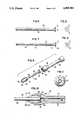
- FIG. 1is an exploded perspective view of a first embodiment of the present invention.
- FIG. 2is a longitudinal cross-sectional view of the embodiment of FIG. 1.
- FIG. 3is a longitudinal sectional view of the retaining nut and tube of the embodiment of FIG. 1.
- FIG. 4is an end view of the retaining nut and tube of FIG. 3.
- FIG. 5is an elevational view of a first tube design of the present invention.
- FIG. 6is an end view of the tube of FIG. 5.
- FIG. 7is an elevational view of a second tube design of the present invention.
- FIG. 8is an end view of the tube of FIG. 7.
- FIG. 9is an exploded perspective view of a second embodiment of the present invention.
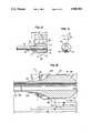
- FIG. 10is longitudinal cross-sectional view of the embodiment of FIG. 9.
- FIG. 11is a cross-sectional view taken along line 11--11 of FIG. 10.
- FIG. 12is a cross-sectional view of the retaining nut and tube of the embodiment of FIG. 9 shown assembled together.
- FIG. 13is an end view of the assembled retaining nut and tube of FIG. 12.
- FIG. 14is an exploded perspective view of a third embodiment of the present invention.
- FIG. 15is a longitudinal cross-sectional view of the embodiment of FIG. 14.
- FIG. 16is an enlarged cross-sectional view of the integral nut-tube member of the assembly of FIG. 14 illustrated in isolation.
- FIG. 17is a plan view of a wrench for tightening the retaining nut relative to the horn of any of the embodiments herein.
- FIG. 18is a right end view of the wrench of FIG. 17.
- FIG. 19is a fragmentary side view of a sample ultrasonic surgical cutting instrument using the ultrasonic cutting tip assembly of FIGS. 9-13.
- an ultrasonic cutting tip assemblyadaptable to generally any ultrasonic surgical cutting instrument or handpiece is illustrated generally at 30.
- the assembly 30includes a transition horn 32 which is operatively couplable to an ultrasonic transducer of the ultrasonic surgical cutting instrument or handpiece as will be more apparent from the later description relative to FIG. 19.
- the transducerconverts high frequency electrical energy to high frequency mechanical vibration to be transmitted to the surgical site. See e.g., International application No. PCT/US87/00696, entitled “Method and Apparatus for Ultrasonic Surgical Fragmentation" published under WO87/05793.
- a retaining nut shown generally at 36is provided to be threaded into position to hold the proximal end 38 of the tube 34 and the transition horn 32 together so that ultrasonic vibrations from the ultrasonic transducer can thereby be efficiently transmitted to the tube 34 and emitted from the distal end 40 of the tube 34 to the tissue at the surgical site.
- the horn 32 at its distal endhas a threaded portion 44 on its outside surface.
- the retaining nut 36 at its proximal endsimilarly has internal threads 46, as best shown in FIG. 2, which are adapted to thread on to the horn threaded portion 44.
- the tube 34 at its proximal endhas an annular flange 50 and three equally-spaced tabs 52 extending out therefrom.
- the retaining nut 36preferably comprises a 3AL-2.5 V or 6AL-4 V titanium nut for strength, improved manufacturing dimensional accuracy, optimal finish, biocompatibility and low tooling cost, and it can be machined from a solid or tubular piece of titanium.
- the retaining nut 36has an opening 54 extending longitudinally through it and the distal end 40 of the tube 34 passes out through it until the annular flange 50 engages an annular internal shoulder 56 in the tube 34 as best shown in FIG. 2.
- the shoulder 56is configured to be slightly smaller than the outer diameter of the tabs 52 so that an interference fit is thereby defined to more firmly hold the tube 34 to the nut 36 and eliminate seperation during attachment to the transition horn 32.
- the design of assembly 30allows for a minimum contact of the walls of the tube 34 to the retaining nut 36 thereby minimizing any ferriting corrosion, and allowing for a long extending tube length to be used.
- the nut 36has lengths in inches of 0.30, 0.240, 0.140, 0.055, 0.050, 0.025, and 0.010, as shown respectively at 57a, 57b, 57c, 57d, 57e, 57f and 57g, angles of forty-five degrees as shown at 58a and 58b, an angle of 6°27'30" at 58c, a width of 0.015 at 59, widths of 0.015 and 0.030 at 61a and 61b in FIG. 4 and diameters of 0.095, 0.054, 0.150, 0.002 and 0.115, as shown at 62a, 62b, 62c, 62d and 62e.
- the distal tip 40 of the tube 34is configured to effectively transmit the ultrasonic energy to the surgical site and preferably has a flat ninety degree configuration as illustrated, but alternatively may have a curved or a cut angled or any other suitable configuration. See e.g. U.S. Pat. No. 3,990,452.
- the distal tip 40itself defines a thin wall, very sharp cutting edge.
- the tube 34is preferably formed of stainless steel to minimize its unit cost and weight, to optimize the finish thereof and to provide greater strength and design flexibility.
- the tube 34is hollow thereby defining a longitudinal channel 63 so that fluid and matter sucked through the distal tip 40 thereof can be aspirated through the entire length of the tube and then through the longitudinal channel 64 of the horn 32 and to a suitable container (not shown) as will become more apparent from the discussion to follow relative to FIG. 19.
- FIG. 5is an elevational view of a tube 66 which can be used with the assembly 30 of FIG. 1 and with a small end portion thereof broken away to illustrate its hollow configuration.
- the tube 66is seen to simply comprise a cylinder 68 having a wall thickness of 0.0025 inch and an outer diameter of 0.042 inch.
- the flange 70 thereofhas a thickness of 0.004 inch and the tube 66 has a length of 1.15 inch.
- the flange 70has an outer diameter of 0.092 inch and each of the three radial tabs 72 thereon has a radial length of 0.003 inch and a width of 0.105 inch. It is noted in this regard that prior art tubes typically have a length shorter than 0.75 inches and a wall thickness greater than 0.004 inch.
- the flange 70can range from about 5 degrees to 90 degrees.
- FIGS. 7 and 8A second embodiment of a tube, which can be used with the assembly 30 and is also preferably formed of stainless steel, is illustrated in FIGS. 7 and 8 generally at 74.
- Tube 74can be used for smaller incision procedures, and it is seen to comprise a cylindrical distal portion 76 having a distal portion outer diameter and a cylindrical proximal portion 78 adjoining the end flange 80 and having a proximal portion outer diameter.
- the proximal portion outer diameteris greater than the distal portion outer diameter and a conical portion 82 between and connecting the proximal and distal portions and tapering with an angle of seven degrees ⁇ three degrees is provided having its outer diameter tapering from the proximal portion 78 to the distal portion 76.
- Tabs 84can be provided on the end flange 80.
- the distal portion outer diameteris 0.030 inch
- the distal portion wall thicknessis 0.0025 inch
- the proximal portion outer diameteris 0.042 inch
- the tubehas a length of 1.150 inch
- the distal portionhas a length of 0.900 inch.
- the flanges of either one of these tube embodimentscan be formed by swaging.
- FIGS. 9 through 11A second and preferred ultrasonic cutting tool assembly is illustrated in FIGS. 9 through 11 generally at 90 and either one of the tube designs of FIGS. 5 or 7 can be used therefor but preferably the tabs 72, 86 thereof are to be omitted.
- the cutting tool assembly 90includes a transition horn 92 having a cylindrical portion 94 with a bulbous enlarged member 96 at its distal end.
- the curved connection surface 98 therebetweenhas a tangent which is less than or equal to twenty-two and half degrees.
- the enlarged member 96has a large opening 100 extending about three- quarters of the way thereinto, as best seen in FIG. 10, and has internal threads 102 along its surface.
- the threads 102extend to generally the end 104 of the enlarged opening and the opening 100 communicates with a narrower aspiration conduit 106 passing through the rest of the enlarged member 96, and through the cylindrical portion 94.
- the retaining nut 108 of this assemblyis configured to be generally cylindrical in shape with a tapered front end 110 and a short stub portion 112 at its proximal end.
- a rear portion of the retaining nut 108has external 4-80 threads 116 on its outside surface which are adapted to thread into the internal threads 102 of the horn 92.
- conduit 118passes longitudinally through the retaining nut 108.
- Oppositely disposed forward notches 120are formed in the front surface of the retaining nut 106, and the notches 120 are adapted to being engaged by a wrench, as will be discussed later, for manually rotating the nut 108 into threading engagement with the enlarged member 96.
- the retaining nut 108has preferred dimensions in inches of 0.175, 0.140, 0.100, 0.090, 0.025, 0.005, 0.040, 0.020 as shown in FIG.
- the design of the assembly 90provides excellent contact with the outer diameter of the tube 150, and is relatively easy and inexpensive to manufacture.
- the tube 150 of this assemblyhas a cylindrical portion 152 adapted to pass into and through the conduit 118 of the retaining nut 108, and a flange 154 at its proximal end. Then when the cylindrical portion 152 of of the tube is passed out through the conduit 118 of the retaining nut 108 and the retaining nut 108 screwed into the enlarged member 96, the flange 154 is forced against of the internal shoulder 156 of the enlarged member 96 and held securely therein and positioned so that the conduit 158 of the tube 150 is aligned with the conduit 159 in the horn 92.
- a third embodiment of the ultrasonic cutting tip assembly of the present inventionis illustrated generally at 160 in FIGS. 14-16. It is seen therefrom that this embodiment is very similar to cutting tool assembly 90 in that it also has a horn 162 with a central cylindrical portion 164 and a bulbous enlarged member 166 having internal threads 167 therein.
- the retaining nut 168 with the external threads 170 thereonis formed, however, as a single piece shown generally at 171 with the tube 172 in this embodiment, and is preferably made from extruded 3AL-2.5 V titanium.
- the nut 168has a short cylindrical portion 174 generally of the same diameter as the immediately adjacent threaded portion 170 and a cone-shaped portion 176 extends rearwardly therefrom.
- the cylindrical and cone-shaped portions 174, 176 of the retaining nut 168fit tightly against the similarly configured internal cylindrical and cone-shaped portions 178, 180, respectively, in the opening in the enlarged member 166.
- the ultrasonic vibrationsare efficiently transferred to the tube 172 via the integral retaining nut 168.
- the retaining nut 168 of this embodimentalso has a pair of a wrench notches 184 on its forward surface. These elongated notches 184 provide engagement surfaces for a tightening wrench which can be slid into position in the notches and when turned so as to twist the retaining nut 168 about the longitudinal axis of the horn 162 will engage the sides of the notches. Referring to FIG.
- the integral tube/nut member 171has preferred dimensions in inches of 0.040, 0.095, 0.110, 0.175, 0.205, 1.055, 0.015, as shown respectively at 186, 188, 190, 192, 194, 196 and 198, distances to the longitudinal centerline of 0.044, 0.085, 0.115, 0.054, 0.036 (the inner radius of the tube) and 0.044 (the outer radius of the tube) as shown respectively at 200, 202, 204, 206, 208 and 210, an angle 212 of forty-five degrees or less and preferably thirty degrees, an angle 214 which is between forty-five and ninety degrees and preferably forty-five degrees, and a 0.030 minimum inch radius at 216.
- the notches or slots 184are each 0.036 inch wide and positioned one hundred and eighty degrees relative to each other.
- a suitable wrenchis illustrated generally at 217 in FIGS. 17 and 18, is designed in a beer can tab of arrangement and can be adapted to be either disposable or reusable. It fits the tip nut 168 (or 36 or 108) from either the front or back of the wrench.
- the wrench 217is formed by an elongated flat body member 219 of a suitable material, such as a metal or strong plastic, and has at its forward end a slot 218 extending longitudinally a distance towards the center thereof.
- the slot 218has a pair of opposed rounded or semi-circular bibs 220, 222 extending laterally into the channel defined by the slot 218.
- bibs 220, 222are configured to slide into and engage in the notches 184 and then when the body member 219 is grasped and rotated, the retaining nut 168 can be turned and screwed relative to the horn 162.
- Holes 226, 228 therethroughare formed to make the wrench 217 lighter and to allow it to cool down more quickly after having been auto-claved.
- the front and back edges of the bibsare sharp and all other wrench edges are well rounded.
- the wrench 217has a width of 0.38 inch, a length of 0.75 inch and a thickness of 0.040 to 0.062 inch.
- the slot 218has a rearward dimension from the middle of the bib of 0.075 inch and a forward dimension from the middle of the bib forward of 0.15 inch.
- each of the bibshas a radius of 0.125 inch and a distance between the innermost points of the bibs of 0.054 inch.
- FIG. 9the assembly 90 of FIGS. 9 through 11 is illustrated in position in an ultrasonic cutting tool instrument or handpiece shown generally at 230. Since many handpiece constructions are known, such as the "Model 500 Ultrasonic Surgical Handpiece” of The Cooper Companies, Inc., or the site TXR Ultrasonic handpiece, or the Optikon Ultrasonic handpiece and this cutting tip assembly 90 (or 30 or 160) can be adapted for practically any of them, only the forward portion of the handpiece 230 surrounding the cutting tip assembly 90 is illustrated.
- the ultrasonic transducer 232 and the connector 234 thereofare shown schematically.
- the connector 234provides an operative connection between the transducer 232 and the transition horn (a stepped sectional concentrator) 92, and, for example, can simply comprise a rigid mounting of the horn 92 to the transducer 232.
- the handpiece 230includes an outer shell body 236 encircling the cutting tip assembly 90 and having threads 238 at its end.
- An irrigation tube 248 communicating with a suitable irrigation fluid supply (not shown)passes along the outside of the shell body 236 and then passes in through an opening in the shell body 256 adjacent the transition horn 92.
- the irrigation fluidflows from the tube 248 into the passage 250 defined between the outer shell body 236 and the horn 92, to the passage 252 defined between the retaining nut 108 and the tip cap sleeve, into the annular space 254 between the forward portion of the sleeve and the tube 150 and then out the end 256 to the surgical site 258.
- Different manifold and fitting designsare disclosed in International application number PCT/US87/00795 entitled "Irrigation/Aspiration Manifold and Fittings for Ultrasonic Surgical Aspiration System” and published under No. WO87/06116.
- An ultrasonic decoupling sleeve(not shown) as taught in U.S. Pat. No. 4,681,561 to Hood et al can also be provided.
- An aspiration pressure source(not shown) communicates with the aspiration conduit 106 of the transition horn 92 so as to create a suction pressure in this channel whereby material at the surgical site 258 ultrasonically dislodged and cut or emulsified by the ultrasonic energy of the tip of the tube 150 and suspended in the irrigation or body fluids is withdrawn through the interior of the tube 150, the retaining nut 108, and the transition horn 92 and thereby away from the surgical site 258 to a suitable collection container (not shown).
- Systems for controlling the flow of irrigation and aspiration fluidare discussed in International Application No. PCT/US86/01186, published under No. WO86/07249, and also in U.S. Pat. No. 3,693,613.
- each of these cutting tip assembly embodimentsso to eliminate all exposed tip nut surface angles greater than forty-five degrees, a substantial improvement in hydrodynamic performance is achieved.
- the larger the surface areas at ninety degrees to the ultrasonic tool motionthe greater the loading of the tool, the more power required to obtain the tool tip end stroke, and the more cavitation-generated bubbles which can visually obscure the surgical procedure especially cataract removal procedures.
- the present cutting tip assembly designswhich allow the length of the tube to be increased and the wall thickness decreased result in an increase of more than fifty percent in the amplitude the stroke of the tube tip.
- the peak stroke of the tipis at least 0.008 inch and preferably 0.004 inch, and the tip is vibrating at a frequency of between 20 and 250 kHz and preferably 60 kHz.
- An improved coupling between the ultrasonic transition horn and the tip of the ultrasonic toolis provided by the embodiments of this invention.
- a higher compressional force for the torqueis allowed.
- This higher force together with the reduced cross-sectional area of the tube and horn interfacei.e. from an outer diameter of 0.138 inch to an outer diameter of 0.092 inch, provide an improved, lower impedance ultrasonic energy coupling of the tube tip and the horn, and a better fluid seal therebetween.
- the 4-80 thread designreduces the cross-sectional area changes in the ultrasonic horn and thereby reduces acoustic gain variations and increases the stability of the handpiece.
- This tube tip and retaining nut designshould accommodate tensile pressures greater than 30,000 psi and accelerations of 300,000 G minimum.
- the tube designs herein having a thin tube wall thickness, and a constant, non-tapered, non-stepped inner and outer diametersallow a more linear tip gain or stroke increase, a more even tip stress distribution and a lower thermal resistance.
- the reduced cross-sectional area of the tube cutting edge together with increased sharpness thereofsignificantly increase the pressure thereby exerted to break the bonds holding the cataract lens or other material together.
- the high acceleration in the order of 300,000 G and the minimal cross-sectional area of the tip cutting edge provided by its thin wall and ultra-sharp constructionproduce a very high inertial fixation, which means that tissue resection can be performed on harder cataract lenses with less disturbance to surrounding tissue.
- ultrasonic cutting tip assemblies described hereinar firstly used for ophthalmic cataract surgery lens removal, they can also adapted and used with a low pain hypodermic syringe injectors having non-coring, super-lubricated, disposable tips, with general surgical high-speed tissue resection instruments, or with similar instruments. Also, some of the improvements of the present tube-nut design can be used in known one-piece titanium tip-nut constructions.
Landscapes
- Health & Medical Sciences (AREA)
- Surgery (AREA)
- Engineering & Computer Science (AREA)
- Life Sciences & Earth Sciences (AREA)
- Heart & Thoracic Surgery (AREA)
- Nuclear Medicine, Radiotherapy & Molecular Imaging (AREA)
- Mechanical Engineering (AREA)
- Biomedical Technology (AREA)
- Dentistry (AREA)
- Medical Informatics (AREA)
- Molecular Biology (AREA)
- Animal Behavior & Ethology (AREA)
- General Health & Medical Sciences (AREA)
- Public Health (AREA)
- Veterinary Medicine (AREA)
- Surgical Instruments (AREA)
Abstract
Description
This invention relates to ultrasonic surgical cutting instruments and more particularly to the cutting tip assemblies thereof. It also pertains to ultrasonic cutting tip assemblies whose tools or tubes are removable or separable from their ultrasonic transition horns.
Devices which effectively utilize ultrasonic energy for variety of applications are well known in a number of diverse arts. The application of ultrasonically vibrating surgical devices used to fragment and remove unwanted tissue with significant precision and safety has thus led to the development of a number of valuable surgical procedures. Accordingly, the use of ultrasonic aspirators for the fragmentation and surgical removal of tissue from a body has become well known. Initially, the technique of surgical aspiration was applied for the fragmentation and removal of cataract tissue as shown, for example, in U.S. Pat. Nos. 3,589,363 and 3,693,613. (Each of the patents and other documents mentioned herein is hereby incorporated by reference in its entirety.) Later, such techniques were applied with significant success to neurosurgery and other surgical specialties where the application of ultrasonic technology through a small, handheld device for selectively removing tissue on a layer-by-layer basis with precise control has proven feasible.
Certain devices known in the art characteristically produce continuous vibrations having a substantial constant amplitude at a frequency of about twenty to thirty kHz up to about forty to fifty kHz. U.S. Pat. No. 3,589,363 describes one such device which is especially adapted for use in the removal of cataracts, while U.S. Pat. No. 4,063,557 describes a device suitable for the removal of soft tissue which is particularly adapted for removing highly compliant elastic tissue mixed with blood. Such devices are continuously operative when a surgeon wishes to fragment and remove tissue, and generally operate under the control of a footswitch easily accessible to him.
Another ultrasonic surgical instrument is disclosed in U.S. Pat. No. 3,990,452 to Murry et al. Solid or two piece brazed tips for a conical or exponential type of sectional concentrator are illustrated therein. The flats that are subsequently machined on both sides of the tip nut for wrench tightening are right angle notches, which add additional loading to the handpiece and cause additional cavitation bubbles to form. Further, not only does the brazing thereof add an costly step to the manufacturing process, but the copper and silver content can be harmful to the patient's living tissue. Additionally, the large rigid nut of this instrument makes a good, consistent, low impedance acoustical coupling more difficult.
Certain limitations have emerged, and in particular, the promise of safe, effective emulsification and removal of unhealthy tissue and especially hard tissue, such as cataract, while minimizing damage to adjacent healthy tissue, has not yet been fully and truly realized. Many of the prior art ultrasonic surgical cutting or emulsifying instruments ineffectively utilize the power supplied to vibrate them and also have proven to be expensive to manufacture. Further, designs of some instruments do not allow the surgeon to easily visualize the surgical procedure at the surgical site and to manipulate the vibrating tool accurately and consistently during each of the procedures. Thus, a need has arisen for an improved ultrasonic cutting tip assembly design.
Accordingly, it is a principal object of the present invention to provide an improved ultrasonic cutting tip assembly for an ultrasonic surgical cutting instrument having an ultrasonic transducer.
A further object of the present invention is to provide an ultrasonic cutting tip assembly which is less expensive to manufacture so as a practical matter to be truly disposable.
A still further object of the present invention is to provide an improved cutting tip assembly design which minimizes the cavitation erosion of the tip and thereby also the deposition of metallic particulates at the surgical site, such as in the eye.
Another object is to provide an improved cutting tip assembly design which reduces adjacent tissue heating which can cause in cataract removal procedures corneal burns and astigmatism, without deleteriously affecting the surgical removal procedures.
A further object is to provide an improved cutting tip assembly design which minimizes the production of cavitation bubbles which can visually interfere with the surgical procedure such as in a cataract removal procedure.
A still further object of the present invention is to provide an improved cutting tip assembly design which reduces the power required to produce the same tool tip end vibration.
Another object is to provide a improved cutting tip assembly design which reduces the exposure of adjacent healthy tissue to the ultrasound energy.
A further object is to provide an improved cutting tip assembly construction which provides a better fluidic seal for the cutting tip.
A still further object is to provide an improved cutting tip assembly design which handles greater tensile forces and accelerations.
Another object is to provide a cutting tip assembly having improved acoustic gain variations and stability.
A further object is to provide an improved ultrasonic cutting tip assembly which provides increased resulting emulsifying forces.
A still further object is to provide an improved ultrasonic cutting tip assembly design which allows tissue resection to be performed on harder tissue, such as that of a cataract lens, with less damage to adjacent healthy tissue.
Another object is to provide an ultrasonic cutting tip assembly having good, consistent, low impedence acoustical coupling characteristics.
A further object is to provide a cutting tip assembly wherein low cost metal forming technology is utilized in the manufacture thereof and which is efficient in providing a higher stroke for less input power.
Other objects and advantages of the present invention will be more apparent to those skilled in the art from the following description taken in conjunction with the accompanying drawings.
FIG. 1 is an exploded perspective view of a first embodiment of the present invention.
FIG. 2 is a longitudinal cross-sectional view of the embodiment of FIG. 1.
FIG. 3 is a longitudinal sectional view of the retaining nut and tube of the embodiment of FIG. 1.
FIG. 4 is an end view of the retaining nut and tube of FIG. 3.
FIG. 5 is an elevational view of a first tube design of the present invention.
FIG. 6 is an end view of the tube of FIG. 5.
FIG. 7 is an elevational view of a second tube design of the present invention.
FIG. 8 is an end view of the tube of FIG. 7.
FIG. 9 is an exploded perspective view of a second embodiment of the present invention.
FIG. 10 is longitudinal cross-sectional view of the embodiment of FIG. 9.
FIG. 11 is a cross-sectional view taken alongline 11--11 of FIG. 10.
FIG. 12 is a cross-sectional view of the retaining nut and tube of the embodiment of FIG. 9 shown assembled together.
FIG. 13 is an end view of the assembled retaining nut and tube of FIG. 12.
FIG. 14 is an exploded perspective view of a third embodiment of the present invention.
FIG. 15 is a longitudinal cross-sectional view of the embodiment of FIG. 14.
FIG. 16 is an enlarged cross-sectional view of the integral nut-tube member of the assembly of FIG. 14 illustrated in isolation.
FIG. 17 is a plan view of a wrench for tightening the retaining nut relative to the horn of any of the embodiments herein.
FIG. 18 is a right end view of the wrench of FIG. 17.
FIG. 19 is a fragmentary side view of a sample ultrasonic surgical cutting instrument using the ultrasonic cutting tip assembly of FIGS. 9-13.
Referring to FIGS. 1-4, an ultrasonic cutting tip assembly adaptable to generally any ultrasonic surgical cutting instrument or handpiece is illustrated generally at 30. Theassembly 30 includes atransition horn 32 which is operatively couplable to an ultrasonic transducer of the ultrasonic surgical cutting instrument or handpiece as will be more apparent from the later description relative to FIG. 19. The transducer converts high frequency electrical energy to high frequency mechanical vibration to be transmitted to the surgical site. See e.g., International application No. PCT/US87/00696, entitled "Method and Apparatus for Ultrasonic Surgical Fragmentation" published under WO87/05793. It further includes an elongated thin-wall vibration-transmitting tube shown generally at 34 which is separable from thehorn 32 as best illustrated in FIG. 1. A retaining nut shown generally at 36 is provided to be threaded into position to hold theproximal end 38 of thetube 34 and thetransition horn 32 together so that ultrasonic vibrations from the ultrasonic transducer can thereby be efficiently transmitted to thetube 34 and emitted from thedistal end 40 of thetube 34 to the tissue at the surgical site.
Thehorn 32 at its distal end has a threadedportion 44 on its outside surface. The retainingnut 36 at its proximal end similarly hasinternal threads 46, as best shown in FIG. 2, which are adapted to thread on to the horn threadedportion 44. Thetube 34 at its proximal end has anannular flange 50 and three equally-spacedtabs 52 extending out therefrom. The retainingnut 36 preferably comprises a 3AL-2.5 V or 6AL-4 V titanium nut for strength, improved manufacturing dimensional accuracy, optimal finish, biocompatibility and low tooling cost, and it can be machined from a solid or tubular piece of titanium. The retainingnut 36 has anopening 54 extending longitudinally through it and thedistal end 40 of thetube 34 passes out through it until theannular flange 50 engages an annularinternal shoulder 56 in thetube 34 as best shown in FIG. 2. Theshoulder 56 is configured to be slightly smaller than the outer diameter of thetabs 52 so that an interference fit is thereby defined to more firmly hold thetube 34 to thenut 36 and eliminate seperation during attachment to thetransition horn 32.
As can be appreciated, the design ofassembly 30 allows for a minimum contact of the walls of thetube 34 to the retainingnut 36 thereby minimizing any ferriting corrosion, and allowing for a long extending tube length to be used. Referring to FIG. 3, thenut 36 has lengths in inches of 0.30, 0.240, 0.140, 0.055, 0.050, 0.025, and 0.010, as shown respectively at 57a, 57b, 57c, 57d, 57e, 57f and 57g, angles of forty-five degrees as shown at 58a and 58b, an angle of 6°27'30" at 58c, a width of 0.015 at 59, widths of 0.015 and 0.030 at 61a and 61b in FIG. 4 and diameters of 0.095, 0.054, 0.150, 0.002 and 0.115, as shown at 62a, 62b, 62c, 62d and 62e.
Thedistal tip 40 of thetube 34 is configured to effectively transmit the ultrasonic energy to the surgical site and preferably has a flat ninety degree configuration as illustrated, but alternatively may have a curved or a cut angled or any other suitable configuration. See e.g. U.S. Pat. No. 3,990,452. Thedistal tip 40 itself defines a thin wall, very sharp cutting edge. Thetube 34 is preferably formed of stainless steel to minimize its unit cost and weight, to optimize the finish thereof and to provide greater strength and design flexibility. Thetube 34 is hollow thereby defining alongitudinal channel 63 so that fluid and matter sucked through thedistal tip 40 thereof can be aspirated through the entire length of the tube and then through thelongitudinal channel 64 of thehorn 32 and to a suitable container (not shown) as will become more apparent from the discussion to follow relative to FIG. 19.
FIG. 5 is an elevational view of atube 66 which can be used with theassembly 30 of FIG. 1 and with a small end portion thereof broken away to illustrate its hollow configuration. Thetube 66 is seen to simply comprise acylinder 68 having a wall thickness of 0.0025 inch and an outer diameter of 0.042 inch. Theflange 70 thereof has a thickness of 0.004 inch and thetube 66 has a length of 1.15 inch. Theflange 70 has an outer diameter of 0.092 inch and each of the three radial tabs 72 thereon has a radial length of 0.003 inch and a width of 0.105 inch. It is noted in this regard that prior art tubes typically have a length shorter than 0.75 inches and a wall thickness greater than 0.004 inch. Theflange 70 can range from about 5 degrees to 90 degrees.
A second embodiment of a tube, which can be used with theassembly 30 and is also preferably formed of stainless steel, is illustrated in FIGS. 7 and 8 generally at 74.Tube 74 can be used for smaller incision procedures, and it is seen to comprise a cylindricaldistal portion 76 having a distal portion outer diameter and a cylindricalproximal portion 78 adjoining theend flange 80 and having a proximal portion outer diameter. The proximal portion outer diameter is greater than the distal portion outer diameter and aconical portion 82 between and connecting the proximal and distal portions and tapering with an angle of seven degrees ± three degrees is provided having its outer diameter tapering from theproximal portion 78 to thedistal portion 76.Tabs 84 can be provided on theend flange 80. In a preferred construction the distal portion outer diameter is 0.030 inch, the distal portion wall thickness is 0.0025 inch, the proximal portion outer diameter is 0.042 inch, the tube has a length of 1.150 inch and the distal portion has a length of 0.900 inch. The flanges of either one of these tube embodiments can be formed by swaging.
A second and preferred ultrasonic cutting tool assembly is illustrated in FIGS. 9 through 11 generally at 90 and either one of the tube designs of FIGS. 5 or 7 can be used therefor but preferably the tabs 72, 86 thereof are to be omitted. The cuttingtool assembly 90 includes atransition horn 92 having acylindrical portion 94 with a bulbousenlarged member 96 at its distal end. Thecurved connection surface 98 therebetween has a tangent which is less than or equal to twenty-two and half degrees. Theenlarged member 96 has alarge opening 100 extending about three- quarters of the way thereinto, as best seen in FIG. 10, and hasinternal threads 102 along its surface. Thethreads 102 extend to generally the end 104 of the enlarged opening and theopening 100 communicates with anarrower aspiration conduit 106 passing through the rest of theenlarged member 96, and through thecylindrical portion 94. The retainingnut 108 of this assembly is configured to be generally cylindrical in shape with a taperedfront end 110 and ashort stub portion 112 at its proximal end. A rear portion of the retainingnut 108 has external 4-80threads 116 on its outside surface which are adapted to thread into theinternal threads 102 of thehorn 92. As depictedconduit 118 passes longitudinally through the retainingnut 108.
Oppositely disposed forward notches 120 are formed in the front surface of the retainingnut 106, and the notches 120 are adapted to being engaged by a wrench, as will be discussed later, for manually rotating thenut 108 into threading engagement with theenlarged member 96. Referring to FIGS. 12 and 13, the retainingnut 108 has preferred dimensions in inches of 0.175, 0.140, 0.100, 0.090, 0.025, 0.005, 0.040, 0.020 as shown in FIG. 12 respectively at 122, 124, 126, 128, 130, 132, 134, and 136, aradius 138 of 0.062 inch, aminimum radius 139 of 0.008 inch, diameters in inches of 0.113, 0.092 and 0.045, as shown respectively at 140, 142 and 144, and two forty-five degree angles as shown at 146 and 148 and 4-80 threads at 149. The design of theassembly 90 provides excellent contact with the outer diameter of thetube 150, and is relatively easy and inexpensive to manufacture.
Thetube 150 of this assembly, as was previously described with respect to FIGS. 5-8, has acylindrical portion 152 adapted to pass into and through theconduit 118 of the retainingnut 108, and aflange 154 at its proximal end. Then when thecylindrical portion 152 of of the tube is passed out through theconduit 118 of the retainingnut 108 and the retainingnut 108 screwed into theenlarged member 96, theflange 154 is forced against of theinternal shoulder 156 of theenlarged member 96 and held securely therein and positioned so that theconduit 158 of thetube 150 is aligned with the conduit 159 in thehorn 92.
A third embodiment of the ultrasonic cutting tip assembly of the present invention is illustrated generally at 160 in FIGS. 14-16. It is seen therefrom that this embodiment is very similar to cuttingtool assembly 90 in that it also has ahorn 162 with a centralcylindrical portion 164 and a bulbousenlarged member 166 havinginternal threads 167 therein. The retainingnut 168 with theexternal threads 170 thereon is formed, however, as a single piece shown generally at 171 with thetube 172 in this embodiment, and is preferably made from extruded 3AL-2.5 V titanium. At its proximal end thenut 168 has a shortcylindrical portion 174 generally of the same diameter as the immediately adjacent threadedportion 170 and a cone-shapedportion 176 extends rearwardly therefrom. As best shown in FIG. 13, the cylindrical and cone-shapedportions nut 168 fit tightly against the similarly configured internal cylindrical and cone-shapedportions enlarged member 166. When thenut 168 is threaded tightly into and against theenlarged member 166 the ultrasonic vibrations are efficiently transferred to thetube 172 via theintegral retaining nut 168.
The retainingnut 168 of this embodiment also has a pair of awrench notches 184 on its forward surface. Theseelongated notches 184 provide engagement surfaces for a tightening wrench which can be slid into position in the notches and when turned so as to twist the retainingnut 168 about the longitudinal axis of thehorn 162 will engage the sides of the notches. Referring to FIG. 16, the integral tube/nut member 171 has preferred dimensions in inches of 0.040, 0.095, 0.110, 0.175, 0.205, 1.055, 0.015, as shown respectively at 186, 188, 190, 192, 194, 196 and 198, distances to the longitudinal centerline of 0.044, 0.085, 0.115, 0.054, 0.036 (the inner radius of the tube) and 0.044 (the outer radius of the tube) as shown respectively at 200, 202, 204, 206, 208 and 210, anangle 212 of forty-five degrees or less and preferably thirty degrees, anangle 214 which is between forty-five and ninety degrees and preferably forty-five degrees, and a 0.030 minimum inch radius at 216. The notches orslots 184 are each 0.036 inch wide and positioned one hundred and eighty degrees relative to each other.
A suitable wrench is illustrated generally at 217 in FIGS. 17 and 18, is designed in a beer can tab of arrangement and can be adapted to be either disposable or reusable. It fits the tip nut 168 (or 36 or 108) from either the front or back of the wrench. Thewrench 217 is formed by an elongatedflat body member 219 of a suitable material, such as a metal or strong plastic, and has at its forward end aslot 218 extending longitudinally a distance towards the center thereof. Theslot 218 has a pair of opposed rounded orsemi-circular bibs slot 218. Thesebibs notches 184 and then when thebody member 219 is grasped and rotated, the retainingnut 168 can be turned and screwed relative to thehorn 162.Holes wrench 217 lighter and to allow it to cool down more quickly after having been auto-claved. The front and back edges of the bibs are sharp and all other wrench edges are well rounded. Thewrench 217 has a width of 0.38 inch, a length of 0.75 inch and a thickness of 0.040 to 0.062 inch. Theslot 218 has a rearward dimension from the middle of the bib of 0.075 inch and a forward dimension from the middle of the bib forward of 0.15 inch. As best shown in FIG. 15, each of the bibs has a radius of 0.125 inch and a distance between the innermost points of the bibs of 0.054 inch.
In FIG. 9 theassembly 90 of FIGS. 9 through 11 is illustrated in position in an ultrasonic cutting tool instrument or handpiece shown generally at 230. Since many handpiece constructions are known, such as the "Model 500 Ultrasonic Surgical Handpiece" of The Cooper Companies, Inc., or the site TXR Ultrasonic handpiece, or the Optikon Ultrasonic handpiece and this cutting tip assembly 90 (or 30 or 160) can be adapted for practically any of them, only the forward portion of thehandpiece 230 surrounding the cuttingtip assembly 90 is illustrated. Theultrasonic transducer 232 and theconnector 234 thereof are shown schematically. Theconnector 234 provides an operative connection between thetransducer 232 and the transition horn (a stepped sectional concentrator) 92, and, for example, can simply comprise a rigid mounting of thehorn 92 to thetransducer 232.
Thehandpiece 230 includes anouter shell body 236 encircling the cuttingtip assembly 90 and havingthreads 238 at its end. A tip-cap-sleeve 240 havinginternal threads 242 threads onto theshell body 236 and has an outercylindrical portion 244 surrounding the retainingnut 108 and tapering to a narrower elongatedcylindrical portion 246 surrounding thetube 150. Anirrigation tube 248 communicating with a suitable irrigation fluid supply (not shown) passes along the outside of theshell body 236 and then passes in through an opening in theshell body 256 adjacent thetransition horn 92. The irrigation fluid flows from thetube 248 into thepassage 250 defined between theouter shell body 236 and thehorn 92, to thepassage 252 defined between the retainingnut 108 and the tip cap sleeve, into theannular space 254 between the forward portion of the sleeve and thetube 150 and then out theend 256 to thesurgical site 258. Different manifold and fitting designs are disclosed in International application number PCT/US87/00795 entitled "Irrigation/Aspiration Manifold and Fittings for Ultrasonic Surgical Aspiration System" and published under No. WO87/06116. An ultrasonic decoupling sleeve (not shown) as taught in U.S. Pat. No. 4,681,561 to Hood et al can also be provided.
An aspiration pressure source (not shown) communicates with theaspiration conduit 106 of thetransition horn 92 so as to create a suction pressure in this channel whereby material at thesurgical site 258 ultrasonically dislodged and cut or emulsified by the ultrasonic energy of the tip of thetube 150 and suspended in the irrigation or body fluids is withdrawn through the interior of thetube 150, the retainingnut 108, and thetransition horn 92 and thereby away from thesurgical site 258 to a suitable collection container (not shown). Systems for controlling the flow of irrigation and aspiration fluid are discussed in International Application No. PCT/US86/01186, published under No. WO86/07249, and also in U.S. Pat. No. 3,693,613.
By the unique design of each of these cutting tip assembly embodiments so to eliminate all exposed tip nut surface angles greater than forty-five degrees, a substantial improvement in hydrodynamic performance is achieved. The larger the surface areas at ninety degrees to the ultrasonic tool motion, the greater the loading of the tool, the more power required to obtain the tool tip end stroke, and the more cavitation-generated bubbles which can visually obscure the surgical procedure especially cataract removal procedures. Also, the present cutting tip assembly designs which allow the length of the tube to be increased and the wall thickness decreased result in an increase of more than fifty percent in the amplitude the stroke of the tube tip. The peak stroke of the tip is at least 0.008 inch and preferably 0.004 inch, and the tip is vibrating at a frequency of between 20 and 250 kHz and preferably 60 kHz. It is anticipated that in a cataract lens removal procedure this combined tip-nut load reduction and tip tube stroke gain will reduce the ultrasonic handpiece power requirements and the consequent undesirable heating of and ultrasound exposure to the eye by more than fifty percent without any accompanying reduction in the cataract lens removal performance. Also reduction of the ultrasonic energy used during the surgical procedure will reduce the adjacent tissue heating experienced with prior art handpieces. This heating is known to cause corneal burns, astigmatism and other problems. Further, by reducing the cavitation erosion previously experienced, resulting metallic particulate deposition in the eye is thereby reduced.
An improved coupling between the ultrasonic transition horn and the tip of the ultrasonic tool is provided by the embodiments of this invention. By changing from 4-40 threads to 4-80 threads a higher compressional force for the torque is allowed. This higher force together with the reduced cross-sectional area of the tube and horn interface, i.e. from an outer diameter of 0.138 inch to an outer diameter of 0.092 inch, provide an improved, lower impedance ultrasonic energy coupling of the tube tip and the horn, and a better fluid seal therebetween. The 4-80 thread design reduces the cross-sectional area changes in the ultrasonic horn and thereby reduces acoustic gain variations and increases the stability of the handpiece. This tube tip and retaining nut design should accommodate tensile pressures greater than 30,000 psi and accelerations of 300,000 G minimum.
The tube designs herein having a thin tube wall thickness, and a constant, non-tapered, non-stepped inner and outer diameters allow a more linear tip gain or stroke increase, a more even tip stress distribution and a lower thermal resistance. The reduced cross-sectional area of the tube cutting edge together with increased sharpness thereof significantly increase the pressure thereby exerted to break the bonds holding the cataract lens or other material together. The high acceleration in the order of 300,000 G and the minimal cross-sectional area of the tip cutting edge provided by its thin wall and ultra-sharp construction produce a very high inertial fixation, which means that tissue resection can be performed on harder cataract lenses with less disturbance to surrounding tissue.
Although the ultrasonic cutting tip assemblies described herein ar firstly used for ophthalmic cataract surgery lens removal, they can also adapted and used with a low pain hypodermic syringe injectors having non-coring, super-lubricated, disposable tips, with general surgical high-speed tissue resection instruments, or with similar instruments. Also, some of the improvements of the present tube-nut design can be used in known one-piece titanium tip-nut constructions.
The length, angles and other dimensions are for illustration purposes unless indicated as being important or critical.
From the foregoing detailed description, it will be evident that there are a number of changes, adaptations, and modifications of the present invention which come within the province of those skilled in the art. However, it is intended that all such variations not departing from the spirit of this invention be considered as within the scope thereof as limited solely by the claims appended hereto.
Claims (53)
1. For an ultrasonic surgical cutting instrument having an ultrasonic transducer, an ultrasonic cutting tip assembly comprising:
a transition horn operatively couplable to the ultrasonic transducer,
said transition horn having a horn threaded portion,
a vibration-transmitting tube separable from said horn and having a tube proximal end and a tube distal end, and
a retaining nut having a nut threaded portion and adapted so that said nut threaded portion can threadably engage said horn threaded portion to hold said tube proximal end and said transition horn together so that ultrasonic vibrations can thereby be transmitted to said tube and emitted from said tube distal end to the surgical site.
2. The assembly of claim 1 wherein said transition horn has a horn distal end and defines a horn end opening at said horn distal end, said horn threaded portion is disposed inside of said horn end opening, and said nut threaded portion is disposed on an outside surface of said retaining nut.
3. The assembly of claim 2 wherein said tube proximal end is disposed inside of said horn end opening.
4. The assembly of claim 3 wherein said horn end opening has an internal shoulder at a proximal end thereof against which said tube is held by said retaining nut.
5. The assembly of claim 4 wherein said tube has an annular flange at its proximal end which abuts against said internal shoulder when said tube and said transition horn are held together by said retaining nut.
6. The assembly of claim 1 wherein said horn threaded portion comprises external threads thereon and said nut threaded portion comprises internal threads therein such that said retaining nut threads onto said horn.
7. The assembly of claim 1 wherein said tube has a length of 0.850 inch and at its distal tube end a wall thickness of 0.0025 inch.
8. The assembly of claim 1 wherein said horn threaded portion and said nut threaded portion have 4-80 threads.
9. The assembly of claim 1 wherein said retaining nut is formed of titanium.
10. The assembly of claim 9 wherein said titanium is 3AL-2.5 V titanium.
11. The assembly of claim 1 wherein said tube has an annular radial flange at its proximal tip end.
12. The assembly of claim 11 wherein said tube has at least two spaced tabs extending radially out from the circumference of said annular radial flange.
13. The assembly of claim 12 wherein said horn threaded portion comprises external threads thereon and said nut threaded portion comprises internal threads therein such that said retaining nut threads onto said horn, and said at least one tab comprises a plurality of tabs whose outer diameters are larger than the inner diameter of said tip nut so that when assembled together said tube and said retaining nut will be held together by interference.
14. The assembly of claim 12 wherein said at least two tabs comprise three tabs spaced one hundred and twenty degrees ± five degrees relative to each other.
15. The assembly of claim 14 wherein each said tab has a radial length of about 0.003 inch, and a width of about 0.105 inch.
16. The assembly of claim 15 wherein said flange has an outer diameter of about 0.092 inch.
17. The assembly of claim 11 wherein said tube defines a cylinder at whose proximal end said flange is mounted.
18. The assembly of claim 17 wherein said tube has a length of about 1.15 inch, said flange has a thickness of about 0.004 inch, and said cylinder has a wall thickness of about 0.0025 inch and an outer diameter of about 0.042 inch.
19. The assembly of claim 11 wherein said flange is formed by swaging.
20. The assembly of claim 19 wherein said tube is formed of stainless steel.
21. The assembly of claim 1 wherein said distal portion outer diameter is about 0.030 inch and said proximal portion outer diameter is about 0.042 inch.
22. The assembly of claim 21 wherein said tube has a length of about 1.15 inch and said distal portion has a length of about 0.900 inch.
23. The assembly of claim 1 wherein said tube has a radial annular flange at its proximal end and a cylindrical portion extending out therefrom, said retaining nut has a passageway passing therethrough, the proximal open end thereof being adapted to receive said horn therein, said nut threaded portion comprises an internal threaded portion, the distal open end thereof being adapted to receive said cylindrical portion therethrough, and said nut has an annular shoulder in said passageway against which said flange abuts.
24. The assembly of claim 1 wherein said tube comprises a radial annular flange at the proximal end thereof and a cylindrical portion connected thereto, said retaining nut has an outer surface, a passageway extending therethrough, and a nut proximal end through which said passageway passes, said nut threaded portion is on said outer surface, said passageway is adapted to receive said cylindrical portion therethrough and said flange abuts against said nut proximal end.
25. The assembly of claim 1 wherein said retaining nut is separable from said tube.
26. The assembly of claim 1 wherein said retaining nut and said tube define a cylindrical passageway of uniform diameter extending therethrough.
27. The assembly of claim 1 wherein said retaining nut has a nut outer surface and said nut threaded portion is disposed on said nut outer surface.
28. The assembly of claim 1 wherein the ultrasonic surgical cutting instrument includes a sleeve surrounding said retaining nut and extending forwardly past said retaining nut and around said tube.
29. The assembly of claim 1 wherein said forward surface angle is thirty degrees.
30. The assembly of claim 33 wherein said nut threaded portion defines external threads and said retaining nut has its rearward surface angle being generally between forty-five and ninety degrees.
31. The assembly of claim 30 wherein said rearward surface angle is forty-five degrees.
32. The assembly of claim 30 wherein said retaining nut has a generally cylindrical portion between and adjacent the forward and rearward surfaces thereof and said nut threaded portion is on said cylindrical portion.
33. The assembly of claim 1 wherein said horn has a forward cylindrical portion and an enlarged portion at the distal tip of said cylindrical portion and said horn threaded portion is disposed inside of said enlarged portion.
34. The assembly of claim 33 wherein said enlarged portion has its rearward surface angle being not greater than twenty-two and half degrees.
35. The assembly of claim 1 wherein said nut threaded portion defines internal threads and said retaining nut has its rearward surface angle being not greater than forty-five degrees.
36. The assembly of claim 35 wherein said rearward surface angle is thirty degrees.
37. The assembly of claim 36 wherein said forward surface angle is thirty degrees.
38. The assembly of claim 35 wherein said horn has a forward cylindrical portion and said horn threaded portion is positioned on the distal end of said forward cylindrical portion.
39. The assembly of claim 1 wherein said tube distal end has a wall thickness of about 0.0025 inch and an outer diameter of about 0.042 inch.
40. The assembly of claim 1 wherein the ultrasonic surgical cutting instrument includes a sleeve, and said tube is positioned in said sleeve and defines an annular passage therebetween.
41. The assembly of claim 40 wherein the ultrasonic surgical cutting instrument includes an irrigating means for supplying irrigating fluid, and said annular passage is in fluid communication with the irrigating means so that the irrigation fluid can pass therethrough to the surgical site at said tube distal end.
42. The assembly of claim 1 wherein said tube and said retaining nut are adapted to accommodate a force greater than 30,000 psi and an acceleration of at least 300,000 G.
43. The assembly of claim 1 wherein said tube includes a radial flange at the proximal tube end and a cylinder extending from said flange to the distal tube end.
44. The assembly of claim 1 wherein said horn is rigidly joined to the forward end of the ultrasonic transducer.
45. The assembly of claim 1 further comprising an elongated wrench and having a slot at one end thereof and a pair of opposed notch members in said slot and engageable in said notches for rotating said retaining nut relative to said horn.
46. For an ultrasonic surgical cutting instrument having an ultrasonic transducer, an ultrasonic cutting tip assembly comprising:
a transition horn operatively couplable to the ultrasonic transducer,
said transition horn having a horn threaded portion, a vibration-transmitting tube separable from said horn and having a tube proximal end and a tube distal end,
a retaining nut having a nut threaded portion and adapted so that said nut threaded portion can threadably engage said horn threaded portion to hold said tube proximal end and said transition horn together so that ultrasonic vibrations can thereby be transmitted to said tube and emitted from said tube distal end to the surgical site, and
said retaining nut has all of its exposed tip nut surfaces angles being no greater than forty five degrees to lines parallel to the longitudinal centerline of said tube.
47. For an ultrasonic surgical cutting instrument having an ultrasonic transducer, an ultrasonic cutting tip assembly comprising:
a transition horn operatively couplable to the ultrasonic transducer,
said transition horn having a horn threaded portion, a vibration-transmitting tube separable from said horn and having a tube proximal end and a tube distal end,
a retaining nut having a nut threaded portion and adapted so that said nut threaded portion can threadably engage said horn threaded portion to hold said tube proximal end and said transition horn together so that ultrasonic vibrations can thereby be transmitted to said tube and emitted from said tube distal end to the surgical site, and
said tube comprises a cylindrical distal portion having a distal portion outer diameter, a cylindrical proximal portion adjoining said flange and having a proximal portion outer diameter, said proximal portion outer diameter being greater than said distal portion outer diameter, and a conical portion between and connecting said proximal and distal portions, and said conical portion having its outer diameter tapering from said proximal portion to said distal portion.
48. For an ultrasonic surgical cutting instrument having an ultrasonic transducer, an ultrasonic cutting tip assembly comprising:
a transition horn operatively couplable to the ultrasonic transducer,
said transition horn having a horn threaded portion, a vibration-transmitting tube separable from said horn and having a tube proximal end and a tube distal end,
a retaining nut having a nut threaded portion and adapted so that said nut threaded portion can threadably engage said horn threaded portion to hold said tube proximal end and said transition horn together so that ultrasonic vibrations can thereby be transmitted to said tube and emitted from said tube distal end to the surgical site, and
said retaining nut has at least one nut wrench notch extending longitudinally from a forward end of said nut and adapted to be engaged by a wrench for threading said retaining nut on said horn threaded portion.
49. For an ultrasonic surgical cutting instrument having an ultrasonic transducer, an ultrasonic cutting tip assembly comprising:
a transition horn operatively couplable to the ultrasonic transducer,
said transition horn having a horn threaded portion, a vibration-transmitting tube separable from said horn and having a tube proximal end and a tube distal end,
a retaining nut having a nut threaded portion and adapted so that said nut threaded portion can threadably engage said horn threaded portion to hold said tube proximal end and said transition horn together so that ultrasonic vibrations can thereby be transmitted to said tube and emitted from said tube distal end to the surgical site, and
said retaining nut has its forward surface angle being not greater than forty-five degrees to the horizontal.
50. For an ultrasonic surgical cutting instrument having an ultrasonic transducer, an ultrasonic cutting tip assembly comprising:
a transition horn operatively couplable to the ultrasonic transducer,
said transition horn having a horn threaded portion, a vibration-transmitting tube separable from said horn and having a tube proximal end and a tube distal end,
a retaining nut having a nut threaded portion and adapted so that said nut threaded portion can threadably engage said horn threaded portion to hold said tube proximal end and said transition horn together so that ultrasonic vibrations can thereby be transmitted to said tube and emitted from said tube distal end to the surgical site, and
said tube defines an aspiration passageway therethrough for aspirating fragmented tissue and fluid away from the surgical site.
51. For an ultrasonic surgical cutting instrument having an ultrasonic transducer, an ultrasonic cutting tip assembly comprising:
a transition horn operatively couplable to the ultrasonic transducer,
said transition horn having a horn threaded portion, a vibration-transmitting tube separable from said horn and having a tube proximal end and a tube distal end,
a retaining nut having a nut threaded portion and adapted so that said nut threaded portion can threadably engage said horn threaded portion to hold said tube proximal end and said transition horn together so that ultrasonic vibrations can thereby be transmitted to said tube and emitted from said tube distal end to the surgical site, and
said tube distal end defines a tip which is flat and perpendicular to said tube.
52. For an ultrasonic surgical cutting instrument having an ultrasonic transducer, an ultrasonic cutting tip assembly comprising:
a transition horn operatively couplable to the ultrasonic transducer:
said transition horn having a horn threaded portion, a vibration-transmitting tube separable from said horn and having a tube proximal end and a tube distal end,
a retaining nut having a nut threaded portion and adapted so that said nut threaded portion can threadably engage said horn threaded portion to hold said tube proximal end and said transition horn together so that ultrasonic vibrations can thereby be transmitted to said tube and emitted from said tube distal end to the surgical site, and
the ultrasonic surgical cutting instrument includes an irrigation manifold, said retaining nut is enclosed by the manifold, said tube is disposed in the manifold, and an irrigation fluid passageway is defined along said tube between the manifold and said tube.
53. For an ultrasonic surgical cutting instrument having an ultrasonic transducer, an ultrasonic cutting tip assembly comprising:
a transition horn operatively couplable to the ultrasonic transducer,
said transition horn having a horn threaded portion, a vibration-transmitting tube separable from said horn and having a tube proximal end and a tube distal end,
a retaining nut having a nut threaded portion and adapted so that said nut threaded portion can threadably engage said horn threaded portion to hold said tube proximal end and said transition horn together so that ultrasonic vibrations can thereby be transmitted to said tube and emitted from said tube distal end to the surgical site, and
said retaining nut has a pair of spaced wrench-engageable notches on the outer surface thereof.
Priority Applications (7)
| Application Number | Priority Date | Filing Date | Title |
|---|---|---|---|
| US07/260,702US4989583A (en) | 1988-10-21 | 1988-10-21 | Ultrasonic cutting tip assembly |
| EP19890912558EP0394431A4 (en) | 1988-10-21 | 1989-10-19 | Ultrasonic cutting tip assembly |
| AU45170/89AAU615119B2 (en) | 1988-10-21 | 1989-10-19 | Ultrasonic cutting tip assembly |
| JP1511772AJP2578004B2 (en) | 1988-10-21 | 1989-10-19 | Ultrasonic cutting tip assembly |
| PCT/US1989/004651WO1990004362A1 (en) | 1988-10-21 | 1989-10-19 | Ultrasonic cutting tip assembly |
| CA002001153ACA2001153A1 (en) | 1988-10-21 | 1989-10-20 | Ultrasonic cutting tip assembly |
| US07/588,396US5359996A (en) | 1988-10-21 | 1990-09-26 | Ultrasonic cutting tip and assembly |
Applications Claiming Priority (1)
| Application Number | Priority Date | Filing Date | Title |
|---|---|---|---|
| US07/260,702US4989583A (en) | 1988-10-21 | 1988-10-21 | Ultrasonic cutting tip assembly |
Related Child Applications (1)
| Application Number | Title | Priority Date | Filing Date |
|---|---|---|---|
| US07/588,396DivisionUS5359996A (en) | 1988-10-21 | 1990-09-26 | Ultrasonic cutting tip and assembly |
Publications (1)
| Publication Number | Publication Date |
|---|---|
| US4989583Atrue US4989583A (en) | 1991-02-05 |
Family
ID=22990254
Family Applications (2)
| Application Number | Title | Priority Date | Filing Date |
|---|---|---|---|
| US07/260,702Expired - LifetimeUS4989583A (en) | 1988-10-21 | 1988-10-21 | Ultrasonic cutting tip assembly |
| US07/588,396Expired - LifetimeUS5359996A (en) | 1988-10-21 | 1990-09-26 | Ultrasonic cutting tip and assembly |
Family Applications After (1)
| Application Number | Title | Priority Date | Filing Date |
|---|---|---|---|
| US07/588,396Expired - LifetimeUS5359996A (en) | 1988-10-21 | 1990-09-26 | Ultrasonic cutting tip and assembly |
Country Status (6)
| Country | Link |
|---|---|
| US (2) | US4989583A (en) |
| EP (1) | EP0394431A4 (en) |
| JP (1) | JP2578004B2 (en) |
| AU (1) | AU615119B2 (en) |
| CA (1) | CA2001153A1 (en) |
| WO (1) | WO1990004362A1 (en) |
Cited By (140)
| Publication number | Priority date | Publication date | Assignee | Title |
|---|---|---|---|---|
| US5221282A (en)* | 1991-05-29 | 1993-06-22 | Sonokinetics Group | Tapered tip ultrasonic aspirator |
| US5282786A (en)* | 1991-09-23 | 1994-02-01 | Alcon Surgical, Inc. | Infusion sleeve for surgical ultrasonic apparatus |
| USD351095S (en) | 1993-02-02 | 1994-10-04 | Alcon Laboratories, Inc. | Cutting tip wrench |
| US5417672A (en)* | 1993-10-04 | 1995-05-23 | Baxter International Inc. | Connector for coupling an ultrasound transducer to an ultrasound catheter |
| US5427118A (en)* | 1993-10-04 | 1995-06-27 | Baxter International Inc. | Ultrasonic guidewire |
| US5447509A (en)* | 1991-01-11 | 1995-09-05 | Baxter International Inc. | Ultrasound catheter system having modulated output with feedback control |
| US5474530A (en)* | 1991-01-11 | 1995-12-12 | Baxter International Inc. | Angioplasty and ablative devices having onboard ultrasound components and devices and methods for utilizing ultrasound to treat or prevent vasospasm |
| US5676649A (en)* | 1996-10-04 | 1997-10-14 | Alcon Laboratories, Inc. | Phacoemulsification cutting tip |
| WO1998025557A1 (en) | 1996-12-11 | 1998-06-18 | Alcon Laboratories, Inc. | Liquefaction handpiece |
| US5957882A (en)* | 1991-01-11 | 1999-09-28 | Advanced Cardiovascular Systems, Inc. | Ultrasound devices for ablating and removing obstructive matter from anatomical passageways and blood vessels |
| US5989212A (en)* | 1998-06-04 | 1999-11-23 | Alcon Laboratories, Inc. | Pumping chamber for a liquefaction handpiece having a countersink electrode |
| USD426130S (en)* | 1999-03-05 | 2000-06-06 | Alcon Laboratories, Inc. | Cutting tip wrench |
| US6080128A (en)* | 1998-06-04 | 2000-06-27 | Alcon Laboratories, Inc. | Liquefaction handpiece |
| US6156036A (en)* | 1999-06-11 | 2000-12-05 | Alcon Laboratories, Inc. | Surgical handpiece tip |
| WO2000078372A1 (en) | 1999-06-18 | 2000-12-28 | Alcon Laboratories, Inc. | Infusion control system |
| US6179808B1 (en) | 1999-06-18 | 2001-01-30 | Alcon Laboratories, Inc. | Method of controlling the operating parameters of a surgical system |
| US6179805B1 (en) | 1998-06-04 | 2001-01-30 | Alcon Laboratories, Inc. | Liquefracture handpiece |
| US6196989B1 (en) | 1998-06-04 | 2001-03-06 | Alcon Laboratories, Inc. | Tip for liquefracture handpiece |
| EP1090658A1 (en) | 1999-10-05 | 2001-04-11 | OmniSonics Medical Technologies | Ultrasonic medical treatment apparatus |
| WO2001024745A1 (en) | 1999-10-01 | 2001-04-12 | Alcon Laboratories, Inc. | Liquefracture handpiece |
| WO2001030283A1 (en) | 1999-10-28 | 2001-05-03 | Alcon Laboratories, Inc. | Liquefracture handpiece tip |
| WO2001030286A1 (en) | 1999-10-28 | 2001-05-03 | Alcon Laboratories, Inc. | Tip for a liquefracture handpiece |
| US6278218B1 (en) | 1999-04-15 | 2001-08-21 | Ethicon Endo-Surgery, Inc. | Apparatus and method for tuning ultrasonic transducers |
| US6315755B1 (en) | 1998-06-04 | 2001-11-13 | Alcon Manufacturing, Ltd. | Method of controlling a liquefracture handpiece |
| US6398759B1 (en) | 1998-06-04 | 2002-06-04 | Alcon Manufacturing, Ltd. | Liquefracture handpiece tip |
| US20030023257A1 (en)* | 1998-07-16 | 2003-01-30 | Olympus Optical Co., Ltd. | Ultrasonic trocar |
| US6524251B2 (en) | 1999-10-05 | 2003-02-25 | Omnisonics Medical Technologies, Inc. | Ultrasonic device for tissue ablation and sheath for use therewith |
| US20030065263A1 (en)* | 1999-10-05 | 2003-04-03 | Omnisonics Medical Technologies, Inc. | Ultrasonic probe device with rapid attachment and detachment means having a line contact collet |
| WO2003030751A1 (en) | 2001-10-05 | 2003-04-17 | Omnisonics Medical Technologies, Inc. | Method and apparatus for removing plaque from blood vessels using ultrasonic energy |
| US6551337B1 (en) | 1999-10-05 | 2003-04-22 | Omnisonics Medical Technologies, Inc. | Ultrasonic medical device operating in a transverse mode |
| US6575929B2 (en) | 2000-03-14 | 2003-06-10 | Alcon Manufacturing, Ltd. | Pumping chamber for a liquefaction handpiece |
| US6579270B2 (en) | 1998-06-04 | 2003-06-17 | Alcon Manufacturing, Ltd. | Liquefracture handpiece tip |
| WO2003065908A1 (en) | 2002-02-05 | 2003-08-14 | Omnisonics Medical Technologies, Inc. | Apparatus and method for treating gynecological diseases using an ultrsonic medical device operating in a transverse mode |
| US6648847B2 (en) | 1998-06-04 | 2003-11-18 | Alcon Manufacturing, Ltd. | Method of operating a liquefracture handpiece |
| US6647755B2 (en) | 2001-03-07 | 2003-11-18 | Omnisonics Medical Technologies, Inc. | Method for manufacturing small diameter medical devices |
| US6652547B2 (en) | 1999-10-05 | 2003-11-25 | Omnisonics Medical Technologies, Inc. | Apparatus and method of removing occlusions using ultrasonic medical device operating in a transverse mode |
| US20030225366A1 (en)* | 1999-08-31 | 2003-12-04 | Morgan Michael D. | Liquid venting surgical cassette |
| US20030236539A1 (en)* | 1999-10-05 | 2003-12-25 | Omnisonics Medical Technologies, Inc. | Apparatus and method for using an ultrasonic probe to clear a vascular access device |
| US20040019266A1 (en)* | 2002-07-29 | 2004-01-29 | Omnisonics Medical Technologies, Inc. | Apparatus and method for radiopaque coating for an ultrasonic medical device |
| US20040024380A1 (en)* | 2002-08-05 | 2004-02-05 | Darnell Lawrence W. | Container for delivery of fluid to ophthalmic surgical handpiece |
| US20040030349A1 (en)* | 2002-08-08 | 2004-02-12 | Mikhail Boukhny | Liquefaction handpiece tip |
| US20040034340A1 (en)* | 1999-10-13 | 2004-02-19 | Spineco, Inc., An Ohio Corporation | Smart dissector |
| US6695782B2 (en) | 1999-10-05 | 2004-02-24 | Omnisonics Medical Technologies, Inc. | Ultrasonic probe device with rapid attachment and detachment means |
| US6695781B2 (en) | 1999-10-05 | 2004-02-24 | Omnisonics Medical Technologies, Inc. | Ultrasonic medical device for tissue remodeling |
| US6730048B1 (en) | 2002-12-23 | 2004-05-04 | Omnisonics Medical Technologies, Inc. | Apparatus and method for ultrasonic medical device with improved visibility in imaging procedures |
| US6733451B2 (en) | 1999-10-05 | 2004-05-11 | Omnisonics Medical Technologies, Inc. | Apparatus and method for an ultrasonic probe used with a pharmacological agent |
| US20040097996A1 (en)* | 1999-10-05 | 2004-05-20 | Omnisonics Medical Technologies, Inc. | Apparatus and method of removing occlusions using an ultrasonic medical device operating in a transverse mode |
| US20040158150A1 (en)* | 1999-10-05 | 2004-08-12 | Omnisonics Medical Technologies, Inc. | Apparatus and method for an ultrasonic medical device for tissue remodeling |
| US20040176686A1 (en)* | 2002-12-23 | 2004-09-09 | Omnisonics Medical Technologies, Inc. | Apparatus and method for ultrasonic medical device with improved visibility in imaging procedures |
| US20040249401A1 (en)* | 1999-10-05 | 2004-12-09 | Omnisonics Medical Technologies, Inc. | Apparatus and method for an ultrasonic medical device with a non-compliant balloon |
| US20050043629A1 (en)* | 1999-10-05 | 2005-02-24 | Omnisonics Medical Technologies, Inc. | Apparatus and method for an ultrasonic medical device having a probe with a small proximal end |
| US20050043753A1 (en)* | 1999-10-05 | 2005-02-24 | Omnisonics Medical Technologies, Inc. | Apparatus and method for an ultrasonic medical device to treat peripheral artery disease |
| US6860868B1 (en) | 1998-06-04 | 2005-03-01 | Alcon Manufacturing, Ltd. | Surgical handpiece |
| US20050096669A1 (en)* | 1999-10-05 | 2005-05-05 | Omnisonics Medical Technologies, Inc. | Apparatus and method for an ultrasonic medical device to treat coronary thrombus bearing lesions |
| US20050119679A1 (en)* | 1999-10-05 | 2005-06-02 | Omnisonics Medical Technologies, Inc. | Apparatus and method for an ultrasonic medical device to treat chronic total occlusions |
| US6908451B2 (en) | 2002-04-25 | 2005-06-21 | Alcon, Inc. | Liquid venting surgical system |
| US6921385B2 (en) | 2002-08-05 | 2005-07-26 | Alcon, Inc. | Apparatus for delivery of fluid to opthalmic surgical handpiece |
| US20050187514A1 (en)* | 2004-02-09 | 2005-08-25 | Omnisonics Medical Technologies, Inc. | Apparatus and method for an ultrasonic medical device operating in a torsional mode |
| US20050187513A1 (en)* | 2004-02-09 | 2005-08-25 | Omnisonics Medical Technologies, Inc. | Apparatus and method for an ultrasonic medical device operating in torsional and transverse modes |
| US20050192566A1 (en)* | 2004-02-26 | 2005-09-01 | Madden Sean C. | Surgical handpiece tip |
| US20050209561A1 (en)* | 2004-03-22 | 2005-09-22 | Raphael Gordon | Method of detecting surgical events |
| US20050228423A1 (en)* | 2003-02-14 | 2005-10-13 | Alcon, Inc. | Apparatus and method for determining that a surgical fluid container is near empty |
| US20050228425A1 (en)* | 2004-03-22 | 2005-10-13 | Alcon, Inc. | Method of controlling a surgical system based on a load on the cutting tip of a handpiece |
| US20050228424A1 (en)* | 2003-02-14 | 2005-10-13 | Alcon, Inc. | Apparatus and method for determining that a surgical fluid container is near empty |
| US20050256410A1 (en)* | 2004-05-14 | 2005-11-17 | Omnisonics Medical Technologies, Inc. | Apparatus and method for an ultrasonic probe capable of bending with aid of a balloon |
| US20050261628A1 (en)* | 2004-03-22 | 2005-11-24 | Alcon, Inc. | Method of controlling a surgical system based on a rate of change of an operating parameter |
| US20050267488A1 (en)* | 2004-05-13 | 2005-12-01 | Omnisonics Medical Technologies, Inc. | Apparatus and method for using an ultrasonic medical device to treat urolithiasis |
| US20050267504A1 (en)* | 2004-03-22 | 2005-12-01 | Alcon, Inc. | Method of controlling a surgical system based on irrigation flow |
| US20050277869A1 (en)* | 2004-03-22 | 2005-12-15 | Alcon, Inc. | Method of operating an ultrasound handpiece |
| US20060036180A1 (en)* | 2004-08-12 | 2006-02-16 | Mikhail Boukhny | Ultrasonic handpiece |
| US20060041220A1 (en)* | 2004-08-12 | 2006-02-23 | Alcon, Inc. | Ultrasound handpiece |
| EP1647248A1 (en) | 2004-10-14 | 2006-04-19 | Alcon, Inc | Low resistance irrigation system |
| US20060116610A1 (en)* | 2004-11-30 | 2006-06-01 | Omnisonics Medical Technologies, Inc. | Apparatus and method for an ultrasonic medical device with variable frequency drive |
| EP1693027A1 (en) | 2005-02-18 | 2006-08-23 | Alcon, Inc | Phacoemulsification tip |
| US20060189948A1 (en)* | 2005-02-18 | 2006-08-24 | Alcon, Inc. | Phacoemulsification tip |
| EP1700584A1 (en) | 2005-03-08 | 2006-09-13 | Alcon, Inc. | Phacoemulsification tip |
| US20060206050A1 (en)* | 2005-03-08 | 2006-09-14 | Alcon, Inc. | Phacoemulsification tip |
| US20060212038A1 (en)* | 2005-03-16 | 2006-09-21 | Alcon, Inc. | Liquefaction handpiece tip |
| US20060212037A1 (en)* | 2005-03-16 | 2006-09-21 | Alcon, Inc. | Pumping chamber for a liquefaction handpiece |
| US20060212039A1 (en)* | 2005-03-16 | 2006-09-21 | Alcon, Inc. | Pumping chamber for a liquefaction handpiece |
| US20060217739A1 (en)* | 2005-03-22 | 2006-09-28 | Alcon, Inc. | Phacoemulsification tip |
| US20060224116A1 (en)* | 2005-03-16 | 2006-10-05 | Alcon, Inc. | Pumping chamber for a liquefaction handpiece |
| US20060241470A1 (en)* | 2005-03-23 | 2006-10-26 | Misonix Incorporated | Ultrasonic wound debrider probe and method of use |
| EP1716828A1 (en) | 2005-04-26 | 2006-11-02 | Alcon, Inc. | Low resistance irrigation system and apparatus |
| US20070000301A1 (en)* | 2005-06-21 | 2007-01-04 | Todd Kirk W | Reflux control in microsurgical system |
| US20070010730A1 (en)* | 2005-06-28 | 2007-01-11 | Alcon, Inc. | Method of testing a surgical system |
| US20070056596A1 (en)* | 2005-08-31 | 2007-03-15 | Alcon, Inc. | Pulse manipulation for controlling a phacoemulsification surgical system |
| US20070135760A1 (en)* | 2005-12-14 | 2007-06-14 | Williams David L | Occlusion clearance in microsurgical system |
| US20070179438A1 (en)* | 2006-01-30 | 2007-08-02 | Alcon, Inc. | Surge suppression method |
| US20070239102A1 (en)* | 2006-03-01 | 2007-10-11 | Alcon, Inc. | Coupler wrench |
| US20080006096A1 (en)* | 2005-06-27 | 2008-01-10 | Alcon, Inc. | Method of testing a surgical system |
| US20080103430A1 (en)* | 2006-10-30 | 2008-05-01 | Gomez Mario P | Apparatus to facilitate removal of cataracts from the eyes |
| US20080122407A1 (en)* | 2006-06-30 | 2008-05-29 | Alcon, Inc. | System for dynamically adjusting operation of a surgical handpiece |
| US20080125699A1 (en)* | 2006-11-02 | 2008-05-29 | Alcon, Inc. | Irrigation/aspiration system |
| US20080125695A1 (en)* | 2006-06-23 | 2008-05-29 | Hopkins Mark A | Reflux control in microsurgical system |
| US20080125697A1 (en)* | 2006-09-14 | 2008-05-29 | Alcon, Inc. | Method of controlling an irrigation/aspiration system |
| US20080172076A1 (en)* | 2006-11-01 | 2008-07-17 | Alcon, Inc. | Ultrasound apparatus and method of use |
| US20080269667A1 (en)* | 2005-02-24 | 2008-10-30 | Italia Medica S.P.A. | Handpiece for Ultrasonic Electro-Medical Apparatuses |
| US20080281253A1 (en)* | 2007-05-10 | 2008-11-13 | Injev Valentine P | Method of Operating an Ultrasound Handpiece |
| US20090018488A1 (en)* | 2007-07-09 | 2009-01-15 | Davis Sherman G | Method of Priming a Surgical System |
| US20090032123A1 (en)* | 2007-07-31 | 2009-02-05 | Bourne John M | Check Valve |
| US20090032121A1 (en)* | 2007-07-31 | 2009-02-05 | Chon James Y | Check Valve |
| US20090239191A1 (en)* | 2008-03-18 | 2009-09-24 | Helmut Wurm | Securing system |
| US20100036388A1 (en)* | 2006-10-30 | 2010-02-11 | Gomez Mario P | Apparatus to facilitate removal of cataracts of from the eyes |
| US20100036256A1 (en)* | 2008-08-08 | 2010-02-11 | Mikhail Boukhny | Offset ultrasonic hand piece |
| US20100044265A1 (en)* | 2008-07-29 | 2010-02-25 | Ragsdale Donald W | Nestable integrated food tray with waste collection feature |
| US20100057092A1 (en)* | 2008-09-04 | 2010-03-04 | Peterson Robert H | Varying Material Properties of a Single Fluidic Line in Ophthalmology Tubing |
| US20100087846A1 (en)* | 2008-10-06 | 2010-04-08 | Dimalanta Ramon C | Phacoemulsification Tip with Internal Oriented Structures |
| US20100094321A1 (en)* | 2008-10-10 | 2010-04-15 | Takayuki Akahoshi | Ultrasound Handpiece |
| US7708734B2 (en) | 2006-06-30 | 2010-05-04 | Alcon, Inc. | Method for dynamically adjusting operation of a surgical handpiece |
| US7806865B1 (en) | 2009-05-20 | 2010-10-05 | Alcon Research, Ltd. | Pressurized irrigation squeeze band |
| US20100324581A1 (en)* | 2006-12-08 | 2010-12-23 | Alcon, Inc. | Torsional Ultrasound Hand Piece That Eliminates Chatter |
| US7857794B2 (en) | 2004-06-14 | 2010-12-28 | Alcon, Inc. | Handpiece tip |
| US20110004149A1 (en)* | 2009-07-01 | 2011-01-06 | Artsyukhovich Alexander N | Phacoemulsification hook tip |
| US20110112466A1 (en)* | 2009-11-11 | 2011-05-12 | Ramon Carsola Dimalanta | Extended Point Phacoemulsification Tip |
| US20110137232A1 (en)* | 2009-12-09 | 2011-06-09 | Alcon Research, Ltd. | Thermal Management Algorithm For Phacoemulsification System |
| US7967775B2 (en) | 2007-01-09 | 2011-06-28 | Alcon, Inc. | Irrigation/aspiration tip |
| US8136779B2 (en) | 2010-07-27 | 2012-03-20 | Alcon Research, Ltd. | Mounting arrangement for a pressurized irrigation system |
| US8291933B2 (en) | 2008-09-25 | 2012-10-23 | Novartis Ag | Spring-less check valve for a handpiece |
| US8435258B2 (en) | 2006-06-01 | 2013-05-07 | Ethicon Endo-Surgery, Inc. | Mechanism for assembly of ultrasonic instrument |
| US20130310864A1 (en)* | 2012-05-16 | 2013-11-21 | Rafal Z. Jezierski | Reusable blade hub assembly |
| US8631831B2 (en) | 2008-09-04 | 2014-01-21 | Alcon Research, Ltd. | Multi-compliant tubing |
| WO2014039836A1 (en) | 2012-09-07 | 2014-03-13 | Bausch & Lomb Incorporated | Vibrating surgical device for removal of vitreous and other tissue |
| US8784357B2 (en) | 2010-09-15 | 2014-07-22 | Alcon Research, Ltd. | Phacoemulsification hand piece with two independent transducers |
| US8852091B2 (en) | 2012-04-04 | 2014-10-07 | Alcon Research, Ltd. | Devices, systems, and methods for pupil expansion |
| US9113935B2 (en) | 2013-05-09 | 2015-08-25 | Gyrus Acmi, Inc. | Oscillating lithotripter |
| US9132229B2 (en) | 2012-09-13 | 2015-09-15 | Alcon Research, Ltd. | System and method of priming a surgical cassette |
| US9168099B2 (en) | 2012-10-25 | 2015-10-27 | Gyrus Acmi, Inc. | Lithotripsy apparatus using a flexible endoscope |
| US9186164B2 (en) | 2012-10-25 | 2015-11-17 | Gyrus Acmi, Inc. | Impact lithotripsy tip |
| US9320648B2 (en) | 2012-10-04 | 2016-04-26 | Autocam Medical Devices, Llc | Ophthalmic surgical instrument with pre-set tip-to-shell orientation |
| USD767353S1 (en) | 2007-05-22 | 2016-09-27 | Ethicon Endo-Surgery, Llc | Torque wrench for ultrasonic instrument |
| US10258505B2 (en) | 2010-09-17 | 2019-04-16 | Alcon Research, Ltd. | Balanced phacoemulsification tip |
| US10517578B2 (en)* | 2013-10-15 | 2019-12-31 | Hermes Innovations Llc | Laparoscopic device |
| US11166845B2 (en) | 2018-04-03 | 2021-11-09 | Alcon Inc. | Ultrasonic vitreous cutting tip |
| US11484441B2 (en) | 2016-04-29 | 2022-11-01 | Bausch & Lomb Incorporated | Ultrasonic surgical aspiration needle assembly with molded hub |
| US11554214B2 (en) | 2019-06-26 | 2023-01-17 | Meditrina, Inc. | Fluid management system |
| US11896282B2 (en) | 2009-11-13 | 2024-02-13 | Hermes Innovations Llc | Tissue ablation systems and method |
| US11911086B2 (en) | 2008-10-21 | 2024-02-27 | Hermes Innovations Llc | Endometrial ablation devices and systems |
| US12070263B2 (en) | 2008-10-21 | 2024-08-27 | Hermes Innovations Llc | Endometrial ablation method |
| US12220349B2 (en) | 2019-02-06 | 2025-02-11 | Alcon Inc. | Ultrasonic handpiece with floating horn |
Families Citing this family (46)
| Publication number | Priority date | Publication date | Assignee | Title |
|---|---|---|---|---|
| US5318570A (en)* | 1989-01-31 | 1994-06-07 | Advanced Osseous Technologies, Inc. | Ultrasonic tool |
| US5324297A (en)* | 1989-01-31 | 1994-06-28 | Advanced Osseous Technologies, Inc. | Ultrasonic tool connector |
| FR2707154B1 (en)* | 1993-07-08 | 1995-09-15 | Satelec Sa | Ultrasound scalpel. |
| US5472447A (en)* | 1994-05-03 | 1995-12-05 | Abrams; Andrew L. | Power-assisted obturator |
| US5914140A (en)* | 1994-10-25 | 1999-06-22 | General Mills, Inc. | Food products having acoustic bonds between food layers |
| US6047216A (en)* | 1996-04-17 | 2000-04-04 | The United States Of America Represented By The Administrator Of The National Aeronautics And Space Administration | Endothelium preserving microwave treatment for atherosclerosis |
| US5913848A (en) | 1996-06-06 | 1999-06-22 | Luther Medical Products, Inc. | Hard tip over-the-needle catheter and method of manufacturing the same |
| US5772627A (en)* | 1996-07-19 | 1998-06-30 | Neuro Navigational Corp. | Ultrasonic tissue resector for neurosurgery |
| US5989208A (en)* | 1997-05-16 | 1999-11-23 | Nita; Henry | Therapeutic ultrasound system |
| EP1041932B1 (en)* | 1997-12-23 | 2007-11-07 | Misonix, Inc. | Ultrasonic probe with isolated outer cannula |
| US5997499A (en)* | 1998-06-04 | 1999-12-07 | Alcon Laboratories, Inc. | Tip for a liquefaction handpiece |
| US6256859B1 (en) | 1998-09-25 | 2001-07-10 | Sherwood Services Ag | Method of manufacturing an aspiring tool |
| US6855123B2 (en) | 2002-08-02 | 2005-02-15 | Flow Cardia, Inc. | Therapeutic ultrasound system |
| AU5943900A (en) | 1999-11-29 | 2001-05-31 | Alcon Universal Limited | Torsional ultrasound handpiece |
| US9955994B2 (en) | 2002-08-02 | 2018-05-01 | Flowcardia, Inc. | Ultrasound catheter having protective feature against breakage |
| US7220233B2 (en) | 2003-04-08 | 2007-05-22 | Flowcardia, Inc. | Ultrasound catheter devices and methods |
| US6942677B2 (en) | 2003-02-26 | 2005-09-13 | Flowcardia, Inc. | Ultrasound catheter apparatus |
| US7335180B2 (en) | 2003-11-24 | 2008-02-26 | Flowcardia, Inc. | Steerable ultrasound catheter |
| US7137963B2 (en) | 2002-08-26 | 2006-11-21 | Flowcardia, Inc. | Ultrasound catheter for disrupting blood vessel obstructions |
| US7758510B2 (en) | 2003-09-19 | 2010-07-20 | Flowcardia, Inc. | Connector for securing ultrasound catheter to transducer |
| US7540852B2 (en) | 2004-08-26 | 2009-06-02 | Flowcardia, Inc. | Ultrasound catheter devices and methods |
| US8221343B2 (en) | 2005-01-20 | 2012-07-17 | Flowcardia, Inc. | Vibrational catheter devices and methods for making same |
| US20060264970A1 (en)* | 2005-05-19 | 2006-11-23 | Alcon, Inc. | Phacoemulsification tip |
| US9282984B2 (en) | 2006-04-05 | 2016-03-15 | Flowcardia, Inc. | Therapeutic ultrasound system |
| US7942809B2 (en)* | 2006-05-26 | 2011-05-17 | Leban Stanley G | Flexible ultrasonic wire in an endoscope delivery system |
| US7604479B2 (en)* | 2006-07-26 | 2009-10-20 | Buchanan L Stephen | Tip wrench for ultrasonic dental tool |
| US8246643B2 (en) | 2006-11-07 | 2012-08-21 | Flowcardia, Inc. | Ultrasound catheter having improved distal end |
| US20100094198A1 (en)* | 2008-10-14 | 2010-04-15 | Burgett Seth D | Systems and methods for tightening ophthalmic surgical needles |
| US8226566B2 (en) | 2009-06-12 | 2012-07-24 | Flowcardia, Inc. | Device and method for vascular re-entry |
| DE102010033866A1 (en)* | 2010-08-10 | 2012-02-16 | Gebr. Brasseler Gmbh & Co. Kg | Sonic and ultrasonic activatable dental instrument with a Schallspitzenkupplungsvorrichtung and Schallspitzenwerkzeug and dental sound set |
| WO2012068580A1 (en) | 2010-11-19 | 2012-05-24 | Intermountain Invention Management, Llc | Devices for killing tumor cells and related systems and methods |
| US8414605B2 (en) | 2011-07-08 | 2013-04-09 | Alcon Research, Ltd. | Vacuum level control of power for phacoemulsification hand piece |
| US9603615B2 (en) | 2012-01-18 | 2017-03-28 | C.R. Bard, Inc. | Vascular re-entry device |
| RU2640564C2 (en) | 2012-08-02 | 2018-01-09 | Бард Периферэл Васкьюлар | Ultrasonic catheter system |
| US10398463B2 (en) | 2013-06-28 | 2019-09-03 | Misonix Incorporated | Ultrasonic instrument and method for manufacturing same |
| US10702296B2 (en)* | 2016-05-25 | 2020-07-07 | Ethicon Llc | Ultrasonic surgical instrument with cooling conduit |
| US20180140321A1 (en) | 2016-11-23 | 2018-05-24 | C. R. Bard, Inc. | Catheter With Retractable Sheath And Methods Thereof |
| US10575917B2 (en)* | 2016-12-14 | 2020-03-03 | Ethicon Llc | Ultrasonic surgical instrument with integral torque wrench and transverse engagement |
| US10660722B2 (en) | 2016-12-14 | 2020-05-26 | Ethicon Llc | Ultrasonic surgical instrument with integral shaft assembly torque wrench |
| US11596726B2 (en) | 2016-12-17 | 2023-03-07 | C.R. Bard, Inc. | Ultrasound devices for removing clots from catheters and related methods |
| US10758256B2 (en) | 2016-12-22 | 2020-09-01 | C. R. Bard, Inc. | Ultrasonic endovascular catheter |
| US10582983B2 (en) | 2017-02-06 | 2020-03-10 | C. R. Bard, Inc. | Ultrasonic endovascular catheter with a controllable sheath |
| US11690757B2 (en) | 2018-03-30 | 2023-07-04 | Surgical Design Corporation | Surgical hand piece with post-occlusion surge elimination |
| US11207212B2 (en)* | 2018-03-30 | 2021-12-28 | Surgical Design Corporation | Phaco cone work tip for a surgical hand-piece |
| US11369513B2 (en) | 2017-11-22 | 2022-06-28 | Surgical Design Corporation | Low-cost disposable ultrasonic surgical handpiece |
| US11504271B2 (en) | 2018-03-30 | 2022-11-22 | Surgical Design Corporation | Surgical hand-piece with a bottom fluid tube convertible from irrigation to aspiration |
Citations (10)
| Publication number | Priority date | Publication date | Assignee | Title |
|---|---|---|---|---|
| US3589363A (en)* | 1967-07-25 | 1971-06-29 | Cavitron Corp | Material removal apparatus and method employing high frequency vibrations |
| US3693613A (en)* | 1970-12-09 | 1972-09-26 | Cavitron Corp | Surgical handpiece and flow control system for use therewith |
| US3990452A (en)* | 1975-06-13 | 1976-11-09 | Fibra-Sonics, Inc. | Medical machine for performing surgery and treating using ultrasonic energy |
| US4063557A (en)* | 1976-04-01 | 1977-12-20 | Cavitron Corporation | Ultrasonic aspirator |
| US4681561A (en)* | 1986-01-24 | 1987-07-21 | Coopervision, Inc. | Ultrasonic decoupling sleeve |
| US4721107A (en)* | 1985-06-05 | 1988-01-26 | Richard Wolf Gmbh | Instrument for ultrasonic lithotripsy |
| US4748971A (en)* | 1987-01-30 | 1988-06-07 | German Borodulin | Vibrational apparatus for accelerating passage of stones from ureter |
| US4816018A (en)* | 1985-08-02 | 1989-03-28 | Ultramed Corporation | Ultrasonic probe tip |
| US4832021A (en)* | 1985-08-01 | 1989-05-23 | Cooper Lasersonics, Inc. | Apparatus and method for assembly and disassembly of interchangeable surgical acoustic members |
| US4869715A (en)* | 1988-04-21 | 1989-09-26 | Sherburne Fred S | Ultrasonic cone and method of construction |
Family Cites Families (31)
| Publication number | Priority date | Publication date | Assignee | Title |
|---|---|---|---|---|
| US3133351A (en)* | 1957-02-11 | 1964-05-19 | Soundrive Engine Company | Method and apparatus for sonic dental drilling |
| US3732858A (en)* | 1968-09-16 | 1973-05-15 | Surgical Design Corp | Apparatus for removing blood clots, cataracts and other objects from the eye |
| US3584327A (en)* | 1969-04-04 | 1971-06-15 | Fibra Sonics | Ultrasonic transmission system |
| US3823477A (en)* | 1972-02-23 | 1974-07-16 | Pevrick Eng Co Inc | Dental hygiene tool |
| US3945375A (en)* | 1972-04-04 | 1976-03-23 | Surgical Design Corporation | Rotatable surgical instrument |
| DE2242863A1 (en)* | 1972-08-31 | 1974-03-14 | Karl Storz | SURGICAL ELEMENT FOR CRUSHING STONES IN THE HUMAN BODY BY ULTRASOUND |
| DD109296A1 (en)* | 1972-12-21 | 1974-11-05 | ||
| US3942519A (en)* | 1972-12-26 | 1976-03-09 | Ultrasonic Systems, Inc. | Method of ultrasonic cryogenic cataract removal |
| US4011869A (en)* | 1975-08-01 | 1977-03-15 | David Kopf Instruments | Tubular cutting instrument |
| US4425115A (en)* | 1977-12-19 | 1984-01-10 | Wuchinich David G | Ultrasonic resonant vibrator |
| US4428748A (en)* | 1980-04-09 | 1984-01-31 | Peyman Gholam A | Combined ultrasonic emulsifier and mechanical cutter for surgery |
| US4330278A (en)* | 1980-06-30 | 1982-05-18 | Howard Martin | Endodontic flow-through ultrasonic instrument holder device |
| US4921476A (en)* | 1980-10-08 | 1990-05-01 | Cavitron, Inc. | Method for preventing clogging of a surgical aspirator |
| US4516398A (en)* | 1980-10-08 | 1985-05-14 | Cooper Lasersonics, Inc. | Method of use of an ultrasonic surgical pre-aspirator having a orifice by-pass |
| US4417578A (en)* | 1981-03-20 | 1983-11-29 | Surgical Design | Ultrasonic transducer with energy shielding |
| US4517977A (en)* | 1981-07-24 | 1985-05-21 | Unisearch Limited | Co-axial tube surgical infusion/suction cutter tip |
| SU1050702A1 (en)* | 1982-04-13 | 1983-10-30 | Горьковский государственный медицинский институт им.С.М.Кирова | Device for breaking and aspirating cataracta |
| US4535759A (en)* | 1982-09-30 | 1985-08-20 | Cabot Medical Corporation | Ultrasonic medical instrument |
| US4526571A (en)* | 1982-10-15 | 1985-07-02 | Cooper Lasersonics, Inc. | Curved ultrasonic surgical aspirator |
| US4515583A (en)* | 1983-10-17 | 1985-05-07 | Coopervision, Inc. | Operative elliptical probe for ultrasonic surgical instrument and method of its use |
| US4609368A (en)* | 1984-08-22 | 1986-09-02 | Dotson Robert S Jun | Pneumatic ultrasonic surgical handpiece |
| US4589415A (en)* | 1984-08-31 | 1986-05-20 | Haaga John R | Method and system for fragmenting kidney stones |
| US4660573A (en)* | 1985-05-08 | 1987-04-28 | Fibra-Sonics, Inc. | Ultrasonic lithotriptor probe |
| EP0226622A4 (en)* | 1985-06-05 | 1988-08-23 | Coopervision Inc | Connection fitting for a fluid flow regulation system. |
| DE3532405A1 (en)* | 1985-09-11 | 1987-03-19 | Wolf Gmbh Richard | Piezoelectric transducer |
| US4787889A (en)* | 1985-09-27 | 1988-11-29 | Coopervision, Inc. | Rigid, transparent fluid conduit for surgical irrigation |
| US4741731A (en)* | 1986-02-19 | 1988-05-03 | Fibra-Sonics, Inc. | Vented ultrasonic transducer for surgical handpiece |
| US4827911A (en)* | 1986-04-02 | 1989-05-09 | Cooper Lasersonics, Inc. | Method and apparatus for ultrasonic surgical fragmentation and removal of tissue |
| US4867141A (en)* | 1986-06-18 | 1989-09-19 | Olympus Optical Co., Ltd. | Medical treatment apparatus utilizing ultrasonic wave |
| US4729373A (en)* | 1986-12-18 | 1988-03-08 | Peyman Gholam A | Laser-powered surgical device with a vibrating crystalline tip |
| SE459711B (en)* | 1987-03-20 | 1989-07-31 | Swedemed Ab | EQUIPMENT FOR USE IN SURGICAL INTERVENTIONS TO DISPOSE TISSUE |
- 1988
- 1988-10-21USUS07/260,702patent/US4989583A/ennot_activeExpired - Lifetime
- 1989
- 1989-10-19EPEP19890912558patent/EP0394431A4/ennot_activeWithdrawn
- 1989-10-19WOPCT/US1989/004651patent/WO1990004362A1/ennot_activeApplication Discontinuation
- 1989-10-19AUAU45170/89Apatent/AU615119B2/ennot_activeCeased
- 1989-10-19JPJP1511772Apatent/JP2578004B2/ennot_activeExpired - Lifetime
- 1989-10-20CACA002001153Apatent/CA2001153A1/ennot_activeAbandoned
- 1990
- 1990-09-26USUS07/588,396patent/US5359996A/ennot_activeExpired - Lifetime
Patent Citations (10)
| Publication number | Priority date | Publication date | Assignee | Title |
|---|---|---|---|---|
| US3589363A (en)* | 1967-07-25 | 1971-06-29 | Cavitron Corp | Material removal apparatus and method employing high frequency vibrations |
| US3693613A (en)* | 1970-12-09 | 1972-09-26 | Cavitron Corp | Surgical handpiece and flow control system for use therewith |
| US3990452A (en)* | 1975-06-13 | 1976-11-09 | Fibra-Sonics, Inc. | Medical machine for performing surgery and treating using ultrasonic energy |
| US4063557A (en)* | 1976-04-01 | 1977-12-20 | Cavitron Corporation | Ultrasonic aspirator |
| US4721107A (en)* | 1985-06-05 | 1988-01-26 | Richard Wolf Gmbh | Instrument for ultrasonic lithotripsy |
| US4832021A (en)* | 1985-08-01 | 1989-05-23 | Cooper Lasersonics, Inc. | Apparatus and method for assembly and disassembly of interchangeable surgical acoustic members |
| US4816018A (en)* | 1985-08-02 | 1989-03-28 | Ultramed Corporation | Ultrasonic probe tip |
| US4681561A (en)* | 1986-01-24 | 1987-07-21 | Coopervision, Inc. | Ultrasonic decoupling sleeve |
| US4748971A (en)* | 1987-01-30 | 1988-06-07 | German Borodulin | Vibrational apparatus for accelerating passage of stones from ureter |
| US4869715A (en)* | 1988-04-21 | 1989-09-26 | Sherburne Fred S | Ultrasonic cone and method of construction |
Cited By (243)
| Publication number | Priority date | Publication date | Assignee | Title |
|---|---|---|---|---|
| US5957882A (en)* | 1991-01-11 | 1999-09-28 | Advanced Cardiovascular Systems, Inc. | Ultrasound devices for ablating and removing obstructive matter from anatomical passageways and blood vessels |
| US6929632B2 (en) | 1991-01-11 | 2005-08-16 | Advanced Cardiovascular Systems, Inc. | Ultrasonic devices and methods for ablating and removing obstructive matter from anatomical passageways and blood vessels |
| US5447509A (en)* | 1991-01-11 | 1995-09-05 | Baxter International Inc. | Ultrasound catheter system having modulated output with feedback control |
| US5474530A (en)* | 1991-01-11 | 1995-12-12 | Baxter International Inc. | Angioplasty and ablative devices having onboard ultrasound components and devices and methods for utilizing ultrasound to treat or prevent vasospasm |
| US20030009125A1 (en)* | 1991-01-11 | 2003-01-09 | Henry Nita | Ultrasonic devices and methods for ablating and removing obstructive matter from anatomical passageways and blood vessels |
| US5221282A (en)* | 1991-05-29 | 1993-06-22 | Sonokinetics Group | Tapered tip ultrasonic aspirator |
| US5282786A (en)* | 1991-09-23 | 1994-02-01 | Alcon Surgical, Inc. | Infusion sleeve for surgical ultrasonic apparatus |
| USD351095S (en) | 1993-02-02 | 1994-10-04 | Alcon Laboratories, Inc. | Cutting tip wrench |
| US5417672A (en)* | 1993-10-04 | 1995-05-23 | Baxter International Inc. | Connector for coupling an ultrasound transducer to an ultrasound catheter |
| US5427118A (en)* | 1993-10-04 | 1995-06-27 | Baxter International Inc. | Ultrasonic guidewire |
| US5676649A (en)* | 1996-10-04 | 1997-10-14 | Alcon Laboratories, Inc. | Phacoemulsification cutting tip |
| US5885243A (en)* | 1996-12-11 | 1999-03-23 | Alcon Laboratories, Inc. | Liquefaction handpiece |
| WO1998025557A1 (en) | 1996-12-11 | 1998-06-18 | Alcon Laboratories, Inc. | Liquefaction handpiece |
| US6196989B1 (en) | 1998-06-04 | 2001-03-06 | Alcon Laboratories, Inc. | Tip for liquefracture handpiece |
| US6648847B2 (en) | 1998-06-04 | 2003-11-18 | Alcon Manufacturing, Ltd. | Method of operating a liquefracture handpiece |
| US6589201B1 (en) | 1998-06-04 | 2003-07-08 | Alcon Manufacturing, Ltd. | Liquefracture handpiece tip |
| US6589204B1 (en) | 1998-06-04 | 2003-07-08 | Alcon Manufacturing, Ltd. | Method of operating a liquefracture handpiece |
| US6179805B1 (en) | 1998-06-04 | 2001-01-30 | Alcon Laboratories, Inc. | Liquefracture handpiece |
| US6579270B2 (en) | 1998-06-04 | 2003-06-17 | Alcon Manufacturing, Ltd. | Liquefracture handpiece tip |
| US6080128A (en)* | 1998-06-04 | 2000-06-27 | Alcon Laboratories, Inc. | Liquefaction handpiece |
| US5989212A (en)* | 1998-06-04 | 1999-11-23 | Alcon Laboratories, Inc. | Pumping chamber for a liquefaction handpiece having a countersink electrode |
| US6398759B1 (en) | 1998-06-04 | 2002-06-04 | Alcon Manufacturing, Ltd. | Liquefracture handpiece tip |
| US6860868B1 (en) | 1998-06-04 | 2005-03-01 | Alcon Manufacturing, Ltd. | Surgical handpiece |
| US6676628B2 (en) | 1998-06-04 | 2004-01-13 | Alcon Manufacturing, Ltd. | Pumping chamber for a liquefracture handpiece |
| US6331171B1 (en) | 1998-06-04 | 2001-12-18 | Alcon Laboratories, Inc. | Tip for a liquefracture handpiece |
| US6287274B1 (en) | 1998-06-04 | 2001-09-11 | Alcon Manufacturing, Inc. | Liquefaction handpiece |
| US6315755B1 (en) | 1998-06-04 | 2001-11-13 | Alcon Manufacturing, Ltd. | Method of controlling a liquefracture handpiece |
| US20030023257A1 (en)* | 1998-07-16 | 2003-01-30 | Olympus Optical Co., Ltd. | Ultrasonic trocar |
| USD426130S (en)* | 1999-03-05 | 2000-06-06 | Alcon Laboratories, Inc. | Cutting tip wrench |
| US6278218B1 (en) | 1999-04-15 | 2001-08-21 | Ethicon Endo-Surgery, Inc. | Apparatus and method for tuning ultrasonic transducers |
| US6156036A (en)* | 1999-06-11 | 2000-12-05 | Alcon Laboratories, Inc. | Surgical handpiece tip |
| US6491661B1 (en) | 1999-06-18 | 2002-12-10 | Alcon Manufacturing, Ltd. | Infusion control system |
| US6179808B1 (en) | 1999-06-18 | 2001-01-30 | Alcon Laboratories, Inc. | Method of controlling the operating parameters of a surgical system |
| WO2000078372A1 (en) | 1999-06-18 | 2000-12-28 | Alcon Laboratories, Inc. | Infusion control system |
| US20030225366A1 (en)* | 1999-08-31 | 2003-12-04 | Morgan Michael D. | Liquid venting surgical cassette |
| WO2001024745A1 (en) | 1999-10-01 | 2001-04-12 | Alcon Laboratories, Inc. | Liquefracture handpiece |
| US20050043629A1 (en)* | 1999-10-05 | 2005-02-24 | Omnisonics Medical Technologies, Inc. | Apparatus and method for an ultrasonic medical device having a probe with a small proximal end |
| US20050143660A1 (en)* | 1999-10-05 | 2005-06-30 | Omnisonics Medical Technologies, Inc. | Method for removing plaque from blood vessels using ultrasonic energy |
| US20030125645A1 (en)* | 1999-10-05 | 2003-07-03 | Omnisonics Medical Technologies, Inc. | Ultrasonic medical device operating in a transverse mode |
| US6551337B1 (en) | 1999-10-05 | 2003-04-22 | Omnisonics Medical Technologies, Inc. | Ultrasonic medical device operating in a transverse mode |
| US7494468B2 (en) | 1999-10-05 | 2009-02-24 | Omnisonics Medical Technologies, Inc. | Ultrasonic medical device operating in a transverse mode |
| US7503895B2 (en) | 1999-10-05 | 2009-03-17 | Omnisonics Medical Technologies, Inc. | Ultrasonic device for tissue ablation and sheath for use therewith |
| US20030065263A1 (en)* | 1999-10-05 | 2003-04-03 | Omnisonics Medical Technologies, Inc. | Ultrasonic probe device with rapid attachment and detachment means having a line contact collet |
| EP1090658A1 (en) | 1999-10-05 | 2001-04-11 | OmniSonics Medical Technologies | Ultrasonic medical treatment apparatus |
| US6652547B2 (en) | 1999-10-05 | 2003-11-25 | Omnisonics Medical Technologies, Inc. | Apparatus and method of removing occlusions using ultrasonic medical device operating in a transverse mode |
| US6524251B2 (en) | 1999-10-05 | 2003-02-25 | Omnisonics Medical Technologies, Inc. | Ultrasonic device for tissue ablation and sheath for use therewith |
| US6660013B2 (en) | 1999-10-05 | 2003-12-09 | Omnisonics Medical Technologies, Inc. | Apparatus for removing plaque from blood vessels using ultrasonic energy |
| US20030236539A1 (en)* | 1999-10-05 | 2003-12-25 | Omnisonics Medical Technologies, Inc. | Apparatus and method for using an ultrasonic probe to clear a vascular access device |
| US8790359B2 (en) | 1999-10-05 | 2014-07-29 | Cybersonics, Inc. | Medical systems and related methods |
| US20040249401A1 (en)* | 1999-10-05 | 2004-12-09 | Omnisonics Medical Technologies, Inc. | Apparatus and method for an ultrasonic medical device with a non-compliant balloon |
| US20050119679A1 (en)* | 1999-10-05 | 2005-06-02 | Omnisonics Medical Technologies, Inc. | Apparatus and method for an ultrasonic medical device to treat chronic total occlusions |
| US20050096669A1 (en)* | 1999-10-05 | 2005-05-05 | Omnisonics Medical Technologies, Inc. | Apparatus and method for an ultrasonic medical device to treat coronary thrombus bearing lesions |
| US20040162571A1 (en)* | 1999-10-05 | 2004-08-19 | Omnisonics Medical Technologies, Inc. | Apparatus and method for an ultrasonic medical device to treat deep vein thrombosis |
| US6866670B2 (en) | 1999-10-05 | 2005-03-15 | Omnisonics Medical Technologies, Inc. | Apparatus for removing plaque from blood vessels using ultrasonic energy |
| US6695782B2 (en) | 1999-10-05 | 2004-02-24 | Omnisonics Medical Technologies, Inc. | Ultrasonic probe device with rapid attachment and detachment means |
| US6695781B2 (en) | 1999-10-05 | 2004-02-24 | Omnisonics Medical Technologies, Inc. | Ultrasonic medical device for tissue remodeling |
| US20040073244A1 (en)* | 1999-10-05 | 2004-04-15 | Omnisonics Medical Technologies, Inc. | Method and apparatus for removing plaque from blood vessels using ultrasonic energy |
| US20050043753A1 (en)* | 1999-10-05 | 2005-02-24 | Omnisonics Medical Technologies, Inc. | Apparatus and method for an ultrasonic medical device to treat peripheral artery disease |
| US6733451B2 (en) | 1999-10-05 | 2004-05-11 | Omnisonics Medical Technologies, Inc. | Apparatus and method for an ultrasonic probe used with a pharmacological agent |
| US20040097996A1 (en)* | 1999-10-05 | 2004-05-20 | Omnisonics Medical Technologies, Inc. | Apparatus and method of removing occlusions using an ultrasonic medical device operating in a transverse mode |
| US20040158150A1 (en)* | 1999-10-05 | 2004-08-12 | Omnisonics Medical Technologies, Inc. | Apparatus and method for an ultrasonic medical device for tissue remodeling |
| US20040158151A1 (en)* | 1999-10-05 | 2004-08-12 | Omnisonics Medical Technologies, Inc. | Apparatus and method for an ultrasonic probe device with rapid attachment and detachment means |
| US20040034340A1 (en)* | 1999-10-13 | 2004-02-19 | Spineco, Inc., An Ohio Corporation | Smart dissector |
| WO2001030283A1 (en) | 1999-10-28 | 2001-05-03 | Alcon Laboratories, Inc. | Liquefracture handpiece tip |
| WO2001030282A1 (en) | 1999-10-28 | 2001-05-03 | Alcon Laboratories, Inc. | Liquefracture handpiece |
| WO2001030286A1 (en) | 1999-10-28 | 2001-05-03 | Alcon Laboratories, Inc. | Tip for a liquefracture handpiece |
| US6575929B2 (en) | 2000-03-14 | 2003-06-10 | Alcon Manufacturing, Ltd. | Pumping chamber for a liquefaction handpiece |
| US6647755B2 (en) | 2001-03-07 | 2003-11-18 | Omnisonics Medical Technologies, Inc. | Method for manufacturing small diameter medical devices |
| US20040031308A1 (en)* | 2001-03-07 | 2004-02-19 | Omnisonics Medical Technologies, Inc. | Apparatus for manufacturing small diameter medical devices |
| WO2003030751A1 (en) | 2001-10-05 | 2003-04-17 | Omnisonics Medical Technologies, Inc. | Method and apparatus for removing plaque from blood vessels using ultrasonic energy |
| WO2003065908A1 (en) | 2002-02-05 | 2003-08-14 | Omnisonics Medical Technologies, Inc. | Apparatus and method for treating gynecological diseases using an ultrsonic medical device operating in a transverse mode |
| US6908451B2 (en) | 2002-04-25 | 2005-06-21 | Alcon, Inc. | Liquid venting surgical system |
| US20040019266A1 (en)* | 2002-07-29 | 2004-01-29 | Omnisonics Medical Technologies, Inc. | Apparatus and method for radiopaque coating for an ultrasonic medical device |
| US6921385B2 (en) | 2002-08-05 | 2005-07-26 | Alcon, Inc. | Apparatus for delivery of fluid to opthalmic surgical handpiece |
| US20040024380A1 (en)* | 2002-08-05 | 2004-02-05 | Darnell Lawrence W. | Container for delivery of fluid to ophthalmic surgical handpiece |
| US7160268B2 (en) | 2002-08-05 | 2007-01-09 | Alcon, Inc. | Container for delivery of fluid to ophthalmic surgical handpiece |
| US20040030349A1 (en)* | 2002-08-08 | 2004-02-12 | Mikhail Boukhny | Liquefaction handpiece tip |
| US20040176686A1 (en)* | 2002-12-23 | 2004-09-09 | Omnisonics Medical Technologies, Inc. | Apparatus and method for ultrasonic medical device with improved visibility in imaging procedures |
| US6730048B1 (en) | 2002-12-23 | 2004-05-04 | Omnisonics Medical Technologies, Inc. | Apparatus and method for ultrasonic medical device with improved visibility in imaging procedures |
| US7695447B2 (en) | 2003-02-14 | 2010-04-13 | Alcon, Inc. | Apparatus and method for determining that a surgical fluid container is near empty |
| US20050228423A1 (en)* | 2003-02-14 | 2005-10-13 | Alcon, Inc. | Apparatus and method for determining that a surgical fluid container is near empty |
| US20050228424A1 (en)* | 2003-02-14 | 2005-10-13 | Alcon, Inc. | Apparatus and method for determining that a surgical fluid container is near empty |
| US20050187513A1 (en)* | 2004-02-09 | 2005-08-25 | Omnisonics Medical Technologies, Inc. | Apparatus and method for an ultrasonic medical device operating in torsional and transverse modes |
| US7794414B2 (en) | 2004-02-09 | 2010-09-14 | Emigrant Bank, N.A. | Apparatus and method for an ultrasonic medical device operating in torsional and transverse modes |
| US20100331743A1 (en)* | 2004-02-09 | 2010-12-30 | Emigrant Bank, N. A. | Apparatus and method for an ultrasonic medical device operating in torsional and transverse modes |
| US20050187514A1 (en)* | 2004-02-09 | 2005-08-25 | Omnisonics Medical Technologies, Inc. | Apparatus and method for an ultrasonic medical device operating in a torsional mode |
| US20050192566A1 (en)* | 2004-02-26 | 2005-09-01 | Madden Sean C. | Surgical handpiece tip |
| US7276060B2 (en) | 2004-02-26 | 2007-10-02 | Alcon, Inc. | Surgical handpiece tip |
| US8257307B2 (en) | 2004-03-22 | 2012-09-04 | Alcon Research, Ltd. | Method of controlling a surgical system based on a load on the cutting tip of a handpiece |
| US20050267504A1 (en)* | 2004-03-22 | 2005-12-01 | Alcon, Inc. | Method of controlling a surgical system based on irrigation flow |
| US20100036406A1 (en)* | 2004-03-22 | 2010-02-11 | Alcon, Inc. | Method of Controlling a Surgical System Based on a Load on the Cutting Tip of a Handpiece |
| US8048020B2 (en) | 2004-03-22 | 2011-11-01 | Alcon, Inc. | Method of controlling a surgical system based on irrigation flow |
| US7645255B2 (en) | 2004-03-22 | 2010-01-12 | Alcon, Inc. | Method of controlling a surgical system based on irrigation flow |
| US8172786B2 (en) | 2004-03-22 | 2012-05-08 | Alcon Research, Ltd. | Method of operating an ultrasound handpiece |
| US20090306583A1 (en)* | 2004-03-22 | 2009-12-10 | Mikhail Boukhny | Method of Operating An Ultrasound Handpiece |
| US7625388B2 (en) | 2004-03-22 | 2009-12-01 | Alcon, Inc. | Method of controlling a surgical system based on a load on the cutting tip of a handpiece |
| US20050228425A1 (en)* | 2004-03-22 | 2005-10-13 | Alcon, Inc. | Method of controlling a surgical system based on a load on the cutting tip of a handpiece |
| US7572242B2 (en) | 2004-03-22 | 2009-08-11 | Alcon, Inc. | Method of operating an ultrasound handpiece |
| EP2065001A1 (en) | 2004-03-22 | 2009-06-03 | Alcon, Inc. | System for controlling a surgical system based on a rate of change of an operating parameter |
| US8403851B2 (en) | 2004-03-22 | 2013-03-26 | Novartis Ag | Method of controlling a surgical system based on a load on the cutting tip of a handpiece |
| US8430838B2 (en) | 2004-03-22 | 2013-04-30 | Novartis Ag | Method of controlling a surgical system based on irrigation flow |
| US8523812B2 (en) | 2004-03-22 | 2013-09-03 | Alcon Research, Ltd. | Method of controlling a surgical system based on a rate of change of an operating parameter |
| US20050209561A1 (en)* | 2004-03-22 | 2005-09-22 | Raphael Gordon | Method of detecting surgical events |
| US8974412B2 (en) | 2004-03-22 | 2015-03-10 | Novartis Ag | Method of controlling a surgical system based on a load on the cutting tip of a handpiece |
| US9282989B2 (en) | 2004-03-22 | 2016-03-15 | Novartis Ag | Method of controlling a surgical system based on a load on the cutting tip of a handpiece |
| US20050261628A1 (en)* | 2004-03-22 | 2005-11-24 | Alcon, Inc. | Method of controlling a surgical system based on a rate of change of an operating parameter |
| US7811255B2 (en) | 2004-03-22 | 2010-10-12 | Alcon, Inc. | Method of controlling a surgical system based on a rate of change of an operating parameter |
| US7758538B2 (en) | 2004-03-22 | 2010-07-20 | Alcon, Inc. | Method of controlling a surgical system based on irrigation flow |
| US7297137B2 (en) | 2004-03-22 | 2007-11-20 | Alcon, Inc. | Method of detecting surgical events |
| US20110015563A1 (en)* | 2004-03-22 | 2011-01-20 | Alcon, Inc. | Method Of Controlling A Surgical System Based On A Rate Of Change Of An Operating Parameter |
| US7727193B2 (en) | 2004-03-22 | 2010-06-01 | Alcon, Inc. | Method of controlling a surgical system based on a rate of change of an operating parameter |
| US20100130914A1 (en)* | 2004-03-22 | 2010-05-27 | Alcon, Inc. | Method Of Controlling A Surgical System Based On Irrigation Flow |
| US7713202B2 (en) | 2004-03-22 | 2010-05-11 | Alcon, Inc. | Method of controlling a surgical system based on a load on the cutting tip of a handpiece |
| US20050277869A1 (en)* | 2004-03-22 | 2005-12-15 | Alcon, Inc. | Method of operating an ultrasound handpiece |
| US20050261715A1 (en)* | 2004-03-22 | 2005-11-24 | Alcon, Inc. | Method of controlling a surgical system based on a load on the cutting tip of a handpiece |
| US20050267488A1 (en)* | 2004-05-13 | 2005-12-01 | Omnisonics Medical Technologies, Inc. | Apparatus and method for using an ultrasonic medical device to treat urolithiasis |
| US20050256410A1 (en)* | 2004-05-14 | 2005-11-17 | Omnisonics Medical Technologies, Inc. | Apparatus and method for an ultrasonic probe capable of bending with aid of a balloon |
| US7857794B2 (en) | 2004-06-14 | 2010-12-28 | Alcon, Inc. | Handpiece tip |
| US8814894B2 (en) | 2004-08-12 | 2014-08-26 | Novartis Ag | Ultrasound handpiece |
| US20060041220A1 (en)* | 2004-08-12 | 2006-02-23 | Alcon, Inc. | Ultrasound handpiece |
| US7645256B2 (en) | 2004-08-12 | 2010-01-12 | Alcon, Inc. | Ultrasound handpiece |
| US20060036180A1 (en)* | 2004-08-12 | 2006-02-16 | Mikhail Boukhny | Ultrasonic handpiece |
| US20100004585A1 (en)* | 2004-08-12 | 2010-01-07 | Mikhail Boukhny | Ultrasonic Handpiece |
| US8771301B2 (en) | 2004-08-12 | 2014-07-08 | Alcon Research, Ltd. | Ultrasonic handpiece |
| US7651490B2 (en) | 2004-08-12 | 2010-01-26 | Alcon, Inc. | Ultrasonic handpiece |
| EP1647248A1 (en) | 2004-10-14 | 2006-04-19 | Alcon, Inc | Low resistance irrigation system |
| US20060084937A1 (en)* | 2004-10-14 | 2006-04-20 | Takayuki Akahoshi | Low resistance irrigation system |
| US20060116610A1 (en)* | 2004-11-30 | 2006-06-01 | Omnisonics Medical Technologies, Inc. | Apparatus and method for an ultrasonic medical device with variable frequency drive |
| US20060189948A1 (en)* | 2005-02-18 | 2006-08-24 | Alcon, Inc. | Phacoemulsification tip |
| US20060190003A1 (en)* | 2005-02-18 | 2006-08-24 | Alcon, Inc. | Surgical method |
| EP1693027A1 (en) | 2005-02-18 | 2006-08-23 | Alcon, Inc | Phacoemulsification tip |
| US20080269667A1 (en)* | 2005-02-24 | 2008-10-30 | Italia Medica S.P.A. | Handpiece for Ultrasonic Electro-Medical Apparatuses |
| EP1700584A1 (en) | 2005-03-08 | 2006-09-13 | Alcon, Inc. | Phacoemulsification tip |
| US20060206050A1 (en)* | 2005-03-08 | 2006-09-14 | Alcon, Inc. | Phacoemulsification tip |
| US8403951B2 (en) | 2005-03-08 | 2013-03-26 | Novartis Ag | Phacoemulsification tip |
| US20060217672A1 (en)* | 2005-03-08 | 2006-09-28 | Alcon, Inc. | Phacoemulsification tip |
| US7967799B2 (en) | 2005-03-16 | 2011-06-28 | Alcon, Inc. | Liquefaction handpiece tip |
| US20060212038A1 (en)* | 2005-03-16 | 2006-09-21 | Alcon, Inc. | Liquefaction handpiece tip |
| US20060212037A1 (en)* | 2005-03-16 | 2006-09-21 | Alcon, Inc. | Pumping chamber for a liquefaction handpiece |
| US20060212039A1 (en)* | 2005-03-16 | 2006-09-21 | Alcon, Inc. | Pumping chamber for a liquefaction handpiece |
| US20060224116A1 (en)* | 2005-03-16 | 2006-10-05 | Alcon, Inc. | Pumping chamber for a liquefaction handpiece |
| US7758585B2 (en) | 2005-03-16 | 2010-07-20 | Alcon, Inc. | Pumping chamber for a liquefaction handpiece |
| US20060217739A1 (en)* | 2005-03-22 | 2006-09-28 | Alcon, Inc. | Phacoemulsification tip |
| US20060241470A1 (en)* | 2005-03-23 | 2006-10-26 | Misonix Incorporated | Ultrasonic wound debrider probe and method of use |
| US7931611B2 (en)* | 2005-03-23 | 2011-04-26 | Misonix, Incorporated | Ultrasonic wound debrider probe and method of use |
| US20060253062A1 (en)* | 2005-04-26 | 2006-11-09 | Alcon, Inc. | Low resistance irrigation system and apparatus |
| EP1716828A1 (en) | 2005-04-26 | 2006-11-02 | Alcon, Inc. | Low resistance irrigation system and apparatus |
| US20070000301A1 (en)* | 2005-06-21 | 2007-01-04 | Todd Kirk W | Reflux control in microsurgical system |
| US7644603B2 (en) | 2005-06-27 | 2010-01-12 | Alcon, Inc. | Method of testing a surgical system |
| US20080006096A1 (en)* | 2005-06-27 | 2008-01-10 | Alcon, Inc. | Method of testing a surgical system |
| US7648465B2 (en) | 2005-06-28 | 2010-01-19 | Alcon, Inc. | Method of testing a surgical system |
| US20070010730A1 (en)* | 2005-06-28 | 2007-01-11 | Alcon, Inc. | Method of testing a surgical system |
| US20070078379A1 (en)* | 2005-08-31 | 2007-04-05 | Alcon, Inc. | Controlling a phacoemulsification surgical system by transitioning between pulse and burst modes |
| EP1832259A1 (en) | 2005-08-31 | 2007-09-12 | Alcon, Inc | Pulse amplitude manipulation for controlling a phacoemulsification surgical system |
| US20070073214A1 (en)* | 2005-08-31 | 2007-03-29 | Alcon, Inc. | Pulse manipulation for controlling a phacoemulsification surgical system |
| US20070056596A1 (en)* | 2005-08-31 | 2007-03-15 | Alcon, Inc. | Pulse manipulation for controlling a phacoemulsification surgical system |
| US8353297B2 (en) | 2005-08-31 | 2013-01-15 | Novartis Ag | Pulse manipulation for controlling a phacoemulsification surgical system |
| US20070135760A1 (en)* | 2005-12-14 | 2007-06-14 | Williams David L | Occlusion clearance in microsurgical system |
| US20070179438A1 (en)* | 2006-01-30 | 2007-08-02 | Alcon, Inc. | Surge suppression method |
| US20070239102A1 (en)* | 2006-03-01 | 2007-10-11 | Alcon, Inc. | Coupler wrench |
| US7951136B2 (en) | 2006-03-01 | 2011-05-31 | Alcon, Inc. | Coupler wrench |
| US9023072B2 (en) | 2006-06-01 | 2015-05-05 | Ethicon Endo-Surgery, Inc. | Mechanism for assembly of ultrasonic instrument |
| US8435258B2 (en) | 2006-06-01 | 2013-05-07 | Ethicon Endo-Surgery, Inc. | Mechanism for assembly of ultrasonic instrument |
| US20080125695A1 (en)* | 2006-06-23 | 2008-05-29 | Hopkins Mark A | Reflux control in microsurgical system |
| US20090124962A1 (en)* | 2006-06-23 | 2009-05-14 | Hopkins Mark A | Reflux control in microsurgical system |
| US7640119B2 (en) | 2006-06-30 | 2009-12-29 | Alcon, Inc. | System for dynamically adjusting operation of a surgical handpiece |
| US7708734B2 (en) | 2006-06-30 | 2010-05-04 | Alcon, Inc. | Method for dynamically adjusting operation of a surgical handpiece |
| US20080122407A1 (en)* | 2006-06-30 | 2008-05-29 | Alcon, Inc. | System for dynamically adjusting operation of a surgical handpiece |
| US8465467B2 (en) | 2006-09-14 | 2013-06-18 | Novartis Ag | Method of controlling an irrigation/aspiration system |
| US20080125697A1 (en)* | 2006-09-14 | 2008-05-29 | Alcon, Inc. | Method of controlling an irrigation/aspiration system |
| US20100036388A1 (en)* | 2006-10-30 | 2010-02-11 | Gomez Mario P | Apparatus to facilitate removal of cataracts of from the eyes |
| US8142388B2 (en)* | 2006-10-30 | 2012-03-27 | Gomez Mario P | Apparatus to facilitate removal of cataracts of from the eyes |
| US20080103430A1 (en)* | 2006-10-30 | 2008-05-01 | Gomez Mario P | Apparatus to facilitate removal of cataracts from the eyes |
| US20080172076A1 (en)* | 2006-11-01 | 2008-07-17 | Alcon, Inc. | Ultrasound apparatus and method of use |
| US7981074B2 (en) | 2006-11-02 | 2011-07-19 | Novartis Ag | Irrigation/aspiration system |
| US20080125699A1 (en)* | 2006-11-02 | 2008-05-29 | Alcon, Inc. | Irrigation/aspiration system |
| US8579929B2 (en) | 2006-12-08 | 2013-11-12 | Alcon Research, Ltd. | Torsional ultrasound hand piece that eliminates chatter |
| US20100324581A1 (en)* | 2006-12-08 | 2010-12-23 | Alcon, Inc. | Torsional Ultrasound Hand Piece That Eliminates Chatter |
| US7967775B2 (en) | 2007-01-09 | 2011-06-28 | Alcon, Inc. | Irrigation/aspiration tip |
| US20080281253A1 (en)* | 2007-05-10 | 2008-11-13 | Injev Valentine P | Method of Operating an Ultrasound Handpiece |
| US8303530B2 (en) | 2007-05-10 | 2012-11-06 | Novartis Ag | Method of operating an ultrasound handpiece |
| USD767353S1 (en) | 2007-05-22 | 2016-09-27 | Ethicon Endo-Surgery, Llc | Torque wrench for ultrasonic instrument |
| US20090018488A1 (en)* | 2007-07-09 | 2009-01-15 | Davis Sherman G | Method of Priming a Surgical System |
| US20090032121A1 (en)* | 2007-07-31 | 2009-02-05 | Chon James Y | Check Valve |
| US20090032123A1 (en)* | 2007-07-31 | 2009-02-05 | Bourne John M | Check Valve |
| US7849875B2 (en) | 2007-07-31 | 2010-12-14 | Alcon, Inc. | Check valve |
| US20090239191A1 (en)* | 2008-03-18 | 2009-09-24 | Helmut Wurm | Securing system |
| US20100044265A1 (en)* | 2008-07-29 | 2010-02-25 | Ragsdale Donald W | Nestable integrated food tray with waste collection feature |
| US20100036256A1 (en)* | 2008-08-08 | 2010-02-11 | Mikhail Boukhny | Offset ultrasonic hand piece |
| US9149387B2 (en) | 2008-09-04 | 2015-10-06 | Novartis Ag | Varying material properties of a single fluidic line in ophthalmology tubing |
| US8631831B2 (en) | 2008-09-04 | 2014-01-21 | Alcon Research, Ltd. | Multi-compliant tubing |
| US20100057092A1 (en)* | 2008-09-04 | 2010-03-04 | Peterson Robert H | Varying Material Properties of a Single Fluidic Line in Ophthalmology Tubing |
| US8291933B2 (en) | 2008-09-25 | 2012-10-23 | Novartis Ag | Spring-less check valve for a handpiece |
| US8308735B2 (en) | 2008-10-06 | 2012-11-13 | Novartis Ag | Phacoemulsification tip with internal oriented structures |
| US20100087846A1 (en)* | 2008-10-06 | 2010-04-08 | Dimalanta Ramon C | Phacoemulsification Tip with Internal Oriented Structures |
| US20100094321A1 (en)* | 2008-10-10 | 2010-04-15 | Takayuki Akahoshi | Ultrasound Handpiece |
| US11911086B2 (en) | 2008-10-21 | 2024-02-27 | Hermes Innovations Llc | Endometrial ablation devices and systems |
| US12070263B2 (en) | 2008-10-21 | 2024-08-27 | Hermes Innovations Llc | Endometrial ablation method |
| US7806865B1 (en) | 2009-05-20 | 2010-10-05 | Alcon Research, Ltd. | Pressurized irrigation squeeze band |
| US8623040B2 (en) | 2009-07-01 | 2014-01-07 | Alcon Research, Ltd. | Phacoemulsification hook tip |
| US20110004149A1 (en)* | 2009-07-01 | 2011-01-06 | Artsyukhovich Alexander N | Phacoemulsification hook tip |
| US9233021B2 (en) | 2009-07-01 | 2016-01-12 | Alcon Research, Ltd. | Phacoemulsification hook tip |
| US20110112466A1 (en)* | 2009-11-11 | 2011-05-12 | Ramon Carsola Dimalanta | Extended Point Phacoemulsification Tip |
| US11896282B2 (en) | 2009-11-13 | 2024-02-13 | Hermes Innovations Llc | Tissue ablation systems and method |
| US20110137232A1 (en)* | 2009-12-09 | 2011-06-09 | Alcon Research, Ltd. | Thermal Management Algorithm For Phacoemulsification System |
| US8070711B2 (en) | 2009-12-09 | 2011-12-06 | Alcon Research, Ltd. | Thermal management algorithm for phacoemulsification system |
| US8136779B2 (en) | 2010-07-27 | 2012-03-20 | Alcon Research, Ltd. | Mounting arrangement for a pressurized irrigation system |
| US8784357B2 (en) | 2010-09-15 | 2014-07-22 | Alcon Research, Ltd. | Phacoemulsification hand piece with two independent transducers |
| US10258505B2 (en) | 2010-09-17 | 2019-04-16 | Alcon Research, Ltd. | Balanced phacoemulsification tip |
| US8852091B2 (en) | 2012-04-04 | 2014-10-07 | Alcon Research, Ltd. | Devices, systems, and methods for pupil expansion |
| CN104837418A (en)* | 2012-05-16 | 2015-08-12 | 史密夫和内修有限公司 | Reusable blade hub assembly |
| US20130310864A1 (en)* | 2012-05-16 | 2013-11-21 | Rafal Z. Jezierski | Reusable blade hub assembly |
| US11701137B2 (en) | 2012-05-16 | 2023-07-18 | Smith & Nephew, Inc. | Reusable blade hub assembly |
| US10575866B2 (en) | 2012-05-16 | 2020-03-03 | Smith & Nephew, Inc. | Reusable blade hub assembly |
| US9232958B2 (en)* | 2012-05-16 | 2016-01-12 | Smith & Nephew, Inc. | Reusable blade hub assembly |
| EP2892477A4 (en)* | 2012-09-07 | 2016-06-01 | Bausch & Lomb | VIBRANT SURGICAL DEVICE FOR ABLATION OF GLASS BODY AND OTHER FABRICS |
| EP3231403A1 (en)* | 2012-09-07 | 2017-10-18 | Bausch & Lomb Incorporated | Vibrating surgical device for removal of vitreous and other tissue |
| US9498377B2 (en) | 2012-09-07 | 2016-11-22 | Bausch & Lomb Incorporated | Vibrating surgical device for removal of vitreous and other tissue |
| US20170027752A1 (en)* | 2012-09-07 | 2017-02-02 | Bausch & Lomb Incorporated | Vibrating Surgical Device for Removal of Vitreous and Other Tissue |
| CN104640522B (en)* | 2012-09-07 | 2017-02-22 | 博士伦公司 | Vibratory surgical device for removal of vitreous and other tissues |
| CN106974761A (en)* | 2012-09-07 | 2017-07-25 | 博士伦公司 | Vibration surgery device for removing vitreum and other tissues |
| AU2013312316B2 (en)* | 2012-09-07 | 2017-09-28 | Bausch & Lomb Incorporated | Vibrating surgical device for removal of vitreous and other tissue |
| US10987246B2 (en)* | 2012-09-07 | 2021-04-27 | Bausch & Lomb Incorporated | Vibrating surgical device for removal of vitreous and other tissue |
| WO2014039836A1 (en) | 2012-09-07 | 2014-03-13 | Bausch & Lomb Incorporated | Vibrating surgical device for removal of vitreous and other tissue |
| CN104640522A (en)* | 2012-09-07 | 2015-05-20 | 博士伦公司 | Vibratory surgical device for removal of vitreous and other tissues |
| AU2017221876B2 (en)* | 2012-09-07 | 2019-06-27 | Bausch & Lomb Incorporated | Vibrating surgical device for removal of vitreous and other tissue |
| US9132229B2 (en) | 2012-09-13 | 2015-09-15 | Alcon Research, Ltd. | System and method of priming a surgical cassette |
| US10271988B2 (en) | 2012-10-04 | 2019-04-30 | Autocam Medical Devices, Llc | Ophthalmic surgical instrument with pre-set tip-to-shell orientation |
| US9320648B2 (en) | 2012-10-04 | 2016-04-26 | Autocam Medical Devices, Llc | Ophthalmic surgical instrument with pre-set tip-to-shell orientation |
| US9168099B2 (en) | 2012-10-25 | 2015-10-27 | Gyrus Acmi, Inc. | Lithotripsy apparatus using a flexible endoscope |
| US11284912B2 (en) | 2012-10-25 | 2022-03-29 | Gyrus Acmi, Inc. | Lithotripsy apparatus using a flexible endoscope |
| US9186164B2 (en) | 2012-10-25 | 2015-11-17 | Gyrus Acmi, Inc. | Impact lithotripsy tip |
| US9113935B2 (en) | 2013-05-09 | 2015-08-25 | Gyrus Acmi, Inc. | Oscillating lithotripter |
| US11109874B2 (en) | 2013-05-09 | 2021-09-07 | Gyrus Acmi, Inc. | Oscillating lithotripter |
| US9974552B2 (en) | 2013-05-09 | 2018-05-22 | Gyrus Acmi, Inc. | Oscillating lithotripter |
| US10813653B2 (en) | 2013-05-09 | 2020-10-27 | Gyrus Acmi, Inc. | Oscillating lithotripter |
| US11911055B2 (en) | 2013-05-09 | 2024-02-27 | Gyrus Acmi, Inc. | Oscillating lithotripter |
| US11259787B2 (en) | 2013-10-15 | 2022-03-01 | Hermes Innovations Llc | Laparoscopic device |
| US10517578B2 (en)* | 2013-10-15 | 2019-12-31 | Hermes Innovations Llc | Laparoscopic device |
| US11484441B2 (en) | 2016-04-29 | 2022-11-01 | Bausch & Lomb Incorporated | Ultrasonic surgical aspiration needle assembly with molded hub |
| US11166845B2 (en) | 2018-04-03 | 2021-11-09 | Alcon Inc. | Ultrasonic vitreous cutting tip |
| US12220349B2 (en) | 2019-02-06 | 2025-02-11 | Alcon Inc. | Ultrasonic handpiece with floating horn |
| US11554214B2 (en) | 2019-06-26 | 2023-01-17 | Meditrina, Inc. | Fluid management system |
Also Published As
| Publication number | Publication date |
|---|---|
| JP2578004B2 (en) | 1997-02-05 |
| AU4517089A (en) | 1990-05-14 |
| EP0394431A4 (en) | 1991-05-15 |
| EP0394431A1 (en) | 1990-10-31 |
| AU615119B2 (en) | 1991-09-19 |
| WO1990004362A1 (en) | 1990-05-03 |
| JPH03501700A (en) | 1991-04-18 |
| CA2001153A1 (en) | 1990-04-21 |
| US5359996A (en) | 1994-11-01 |
Similar Documents
| Publication | Publication Date | Title |
|---|---|---|
| US4989583A (en) | Ultrasonic cutting tip assembly | |
| US5562610A (en) | Needle for ultrasonic surgical probe | |
| US6256859B1 (en) | Method of manufacturing an aspiring tool | |
| CA1166676A (en) | Ultrasonic magnetostrictive resonant vibrator | |
| US5562609A (en) | Ultrasonic surgical probe | |
| US7714481B2 (en) | Ultrasonic treatment apparatus | |
| EP1192907B1 (en) | Ultrasonic scalpel blade | |
| US9421027B2 (en) | Method of creating a shear stress field with medical device | |
| JPS63502162A (en) | Surgical instrument with ultrasonic decoupling sleeve | |
| US20010012922A1 (en) | Protective sheath and method for ultrasonic probes | |
| JPH0767464B2 (en) | Device for curettage or excision of biological tissue by instruments vibrating at ultrasonic frequencies | |
| WO2014116886A2 (en) | Ultrasonic tip assembly | |
| US20160374706A1 (en) | Shear stress ultrasonic cutting blade | |
| US6234993B1 (en) | Low profile phaco handpiece | |
| JP2024079691A (en) | Ultrasound tip with raised portion defining front suction hole | |
| US20050159758A1 (en) | Ophthalmic irrigation-aspiration system | |
| EP1311197A4 (en) | ULTRASOUND SHARP BLADE WITH COOLING | |
| CN116829076A (en) | Ultrasonic surgical assembly with air cooled wide blade and irrigation sleeve | |
| WO2023138112A1 (en) | Phacoemulsification perfusion assembly | |
| JPH04212338A (en) | Ultrasonic treating device | |
| JPS6244937B2 (en) | ||
| EP4262572B1 (en) | Irrigation sleeve for ultrasonic surgical assembly | |
| CN120022056A (en) | Ultrasonic surgical instrument | |
| WO1999055240A1 (en) | Irrigation sleeve and ultrasonic needle for phacoemulsification apparatus | |
| JPH0513663B2 (en) |
Legal Events
| Date | Code | Title | Description |
|---|---|---|---|
| AS | Assignment | Owner name:COOPER COMPANIES, INC., 3145 PORTER DRIVE, PALO AL Free format text:ASSIGNMENT OF ASSIGNORS INTEREST.;ASSIGNOR:HOOD, LARRY L.;REEL/FRAME:004990/0113 Effective date:19881206 Owner name:COOPER COMPANIES, INC., CALIFORNIA Free format text:ASSIGNMENT OF ASSIGNORS INTEREST;ASSIGNOR:HOOD, LARRY L.;REEL/FRAME:004990/0113 Effective date:19881206 | |
| AS | Assignment | Owner name:NESTLE, S.A., TEXAS Free format text:ASSIGNMENT OF ASSIGNORS INTEREST.;ASSIGNOR:COOPER COMPANIES, INC., THE;REEL/FRAME:005308/0983 Effective date:19900502 | |
| STCF | Information on status: patent grant | Free format text:PATENTED CASE | |
| FEPP | Fee payment procedure | Free format text:PAYOR NUMBER ASSIGNED (ORIGINAL EVENT CODE: ASPN); ENTITY STATUS OF PATENT OWNER: LARGE ENTITY | |
| FPAY | Fee payment | Year of fee payment:4 | |
| FPAY | Fee payment | Year of fee payment:8 | |
| FPAY | Fee payment | Year of fee payment:12 |