US4989011A - Dual mode phased array antenna system - Google Patents
Dual mode phased array antenna systemDownload PDFInfo
- Publication number
- US4989011A US4989011AUS07/111,909US11190987AUS4989011AUS 4989011 AUS4989011 AUS 4989011AUS 11190987 AUS11190987 AUS 11190987AUS 4989011 AUS4989011 AUS 4989011A
- Authority
- US
- United States
- Prior art keywords
- array
- devices
- antenna system
- ports
- radiating elements
- Prior art date
- Legal status (The legal status is an assumption and is not a legal conclusion. Google has not performed a legal analysis and makes no representation as to the accuracy of the status listed.)
- Expired - Lifetime
Links
- 230000009977dual effectEffects0.000titleabstractdescription32
- 238000009826distributionMethods0.000claimsabstractdescription63
- 239000002131composite materialSubstances0.000claimsabstractdescription50
- 230000005284excitationEffects0.000claimsabstractdescription35
- 230000005670electromagnetic radiationEffects0.000claimsabstractdescription12
- 238000004891communicationMethods0.000claimsdescription12
- 230000010287polarizationEffects0.000claimsdescription12
- 230000005855radiationEffects0.000claimsdescription8
- 238000003491arrayMethods0.000description10
- 239000011159matrix materialSubstances0.000description9
- 230000005540biological transmissionEffects0.000description8
- 238000013461designMethods0.000description7
- 238000000034methodMethods0.000description7
- 230000010363phase shiftEffects0.000description6
- 238000010586diagramMethods0.000description5
- 230000008901benefitEffects0.000description4
- 238000006880cross-coupling reactionMethods0.000description4
- 238000010276constructionMethods0.000description3
- 230000009466transformationEffects0.000description3
- 238000000844transformationMethods0.000description3
- 238000004590computer programMethods0.000description2
- 238000007792additionMethods0.000description1
- 230000002411adverseEffects0.000description1
- 238000004458analytical methodMethods0.000description1
- 230000015572biosynthetic processEffects0.000description1
- 239000004020conductorSubstances0.000description1
- 230000008878couplingEffects0.000description1
- 238000010168coupling processMethods0.000description1
- 238000005859coupling reactionMethods0.000description1
- 230000001066destructive effectEffects0.000description1
- 238000011161developmentMethods0.000description1
- 238000005516engineering processMethods0.000description1
- 230000007613environmental effectEffects0.000description1
- 238000007689inspectionMethods0.000description1
- 238000011835investigationMethods0.000description1
- 238000012986modificationMethods0.000description1
- 230000004048modificationEffects0.000description1
- 238000004806packaging method and processMethods0.000description1
- 238000012552reviewMethods0.000description1
- 239000004065semiconductorSubstances0.000description1
- 238000009987spinningMethods0.000description1
- 238000009424underpinningMethods0.000description1
- 229910000859α-FeInorganic materials0.000description1
Images
Classifications
- H—ELECTRICITY
- H01—ELECTRIC ELEMENTS
- H01Q—ANTENNAS, i.e. RADIO AERIALS
- H01Q25/00—Antennas or antenna systems providing at least two radiating patterns
- H01Q25/04—Multimode antennas
- H—ELECTRICITY
- H01—ELECTRIC ELEMENTS
- H01Q—ANTENNAS, i.e. RADIO AERIALS
- H01Q3/00—Arrangements for changing or varying the orientation or the shape of the directional pattern of the waves radiated from an antenna or antenna system
- H01Q3/26—Arrangements for changing or varying the orientation or the shape of the directional pattern of the waves radiated from an antenna or antenna system varying the relative phase or relative amplitude of energisation between two or more active radiating elements; varying the distribution of energy across a radiating aperture
- H01Q3/30—Arrangements for changing or varying the orientation or the shape of the directional pattern of the waves radiated from an antenna or antenna system varying the relative phase or relative amplitude of energisation between two or more active radiating elements; varying the distribution of energy across a radiating aperture varying the relative phase between the radiating elements of an array
- H01Q3/34—Arrangements for changing or varying the orientation or the shape of the directional pattern of the waves radiated from an antenna or antenna system varying the relative phase or relative amplitude of energisation between two or more active radiating elements; varying the distribution of energy across a radiating aperture varying the relative phase between the radiating elements of an array by electrical means
- H01Q3/40—Arrangements for changing or varying the orientation or the shape of the directional pattern of the waves radiated from an antenna or antenna system varying the relative phase or relative amplitude of energisation between two or more active radiating elements; varying the distribution of energy across a radiating aperture varying the relative phase between the radiating elements of an array by electrical means with phasing matrix
Definitions
- This inventionrelates in general to array antenna systems, and in particular to dual mode array antenna systems suitable for use in communication systems operating at microwave frequencies, and to passive beam-forming networks used therein.
- the two types or modes of polarized signalsare achieved by providing two separate antenna systems, often side by side, which may use a common reflector, but have two separate, single mode, radiating arrays. Often the two antenna systems are designed to have identical coverage in terms of the far-field pattern of the beams produced by the antenna systems.
- the present inventionis directed toward providing technique for minimizing interference between a plurality of independent microwave signals having the same polarization, which are being simultaneously transmitted to the same geographic location in the same general frequency band when each of the signals have the same polarization.
- the antenna system of the present inventiondoes not require the use of any reflectors, but instead typically uses a direct-radiating phased array antenna.
- Phased array antennasare now recognized as the preferred antenna for a number of applications, particularly those requiring multifunction capability.
- Array antennasfeature high power, broad bandwidth, and the ability to withstand adverse environmental conditions.
- a number of referenceshave analyzed the mathematical underpinnings of the operation of phased arrays. See, for example, L. Stark, "Microwave Theory of Phased-Array Antennas--A Review", Proceedings of the IEEE, Vol. 62, No. 12, pp. 1661-1701 (December 1974), and the references cited therein.
- phased arraysVarious combinations of radiating elements, phase shifters and feed systems have been employed to construct phased arrays.
- the types of radiating elements usedhave included horns, dipoles, helices, spiral antennas, polyrods, parabolic dishes and other types of antenna structures.
- the types of phase shifting deviceshave included ferrite phase shifters, p-i-n semiconductor diode devices, and others.
- Feed systemshave included space feeds which use free space propagation and constrained feeds which use transmission line techniques for routing signals from the elements of the array to the central feed point.
- the constrained feedstypically employ power dividers connected by transmission lines. The number and type of power dividers used depends upon the precise purpose to be served with consideration given to power level and attenuation.
- Types of constrained feedsinclude the dual series feed, the hybrid junction corporate feed, parallel-feed beam-forming matrices such as the Butler matrix, and others.
- Large arrays at timeshave used a feed system which includes a Butler matrix feeding subarrays of phase shifters. As far as the inventors are presently aware, all of these features have been developed for single mode phased arrays.
- space-factorrefers here to the complex far-field of an array of isotropic radiators.
- Allenshows that array excitations associated with one input port must be orthogonal to the array excitations for any other input port. If two network inputs are identified as a and b, and if the corresponding excitations at the ith element of the array are a i and b i respectively, then the excitations are orthogonal when ##EQU1## where b i * is the complex conjugate of b i .
- the composite beam produced by a single mode arrayis typically formed from a plurality of individual beams each associated with one of the radiating elements of the array, through constructive and destructive interference between the individual beams, with the interference occurring principally, if not entirely, in space.
- the composite beam which is producedis of the single mode variety since only one information-bearing input signal is provided to the feed network driving the antenna array.
- all of the individual beam signals, and thus the composite beam as wellshare a common electromagnetic polarization.
- a dual mode rotary microwave couplerwith first and second rotatably mounted circular waveguide sections, has first means for launching counter-rotating circularly polarized signals in the first waveguide section, and second means for providing first and second linearly polarized output signals at first and second output ports.
- the microwave couplerprovides an improved and reliable coupling device for applying a pair of output signals from a spinning transmitter multiplexer system through a rotatable joint to a pair of input terminals of a de-spun antenna system such that the signals are isolated during transmission through the coupler, thereby simplifying the design of the multiplexer system.
- the signals applied to the two input terminals of a two horn antenna systemhave a phase quadrature relationship, and each includes components from both output signals.
- the dual mode featurerefers to the provision of two independent antenna terminals, each providing the same gain pattern and polarization sense, but having differing senses of phase progression across the pattern.
- a similar, but more sophisticated dual mode multiphase power divider having two input ports and N output ports, where N is typically an odd integer,is disclosed.
- the power dividerprovides a technique for providing two isolated ports to a single antenna, with the signal from each input port being called a mode and generating nearby the same beam pattern of the same polarization, but with opposite sense of phase progression for each of the two modes.
- counter-rotating circularly polarized signalsare launched from the input ports through a cylindrical waveguide member to the output ports.
- an N-bladed septais disposed near the second or output end of a cylindrical waveguide member to enhance the power division and impedance matching between the N output ports.
- the output portsare connected to a plurality of linearly disposed offset feeds at the focal region of the reflector.
- output signals with equal and opposite phase progressionsare placed equidistantly from and on opposite sides of the focal point of the reflector. It is only by using such an off-center feed design in conjunction with a suitable (e.g., parabolic) reflector that the transmission systems described in these two patents are able to provide two modes having substantially the same coverage. It is also worth noting that the excitation coefficients of the output signals are all of equal amplitude and differ only in phase.
- dual moderefers to the simultaneous transmission (or reception) of two (or more) distinct composite far-field beams of the same polarization sense in the same general frequency band wherein the composite beams have differing electromagnetic characteristics which enable them to be readily distinguished from one another.
- Allenin the above-noted article, was addressing the orthogonality requirements of individual beams where multiple individual beams were generated from a common array of elements connected to a multiple port network.
- we extend beyond Allenby utilizing a linear combination of individual beams to form a composite beam.
- a first linear combination of beamsforms a first composite beam which for convenience we call Mode A.
- a second linear combination of the same individual beamsform a second composite beam, which for convenience we call Mode B.
- a key object of the present inventionis providing the same composite coverage for both Mode A and B beams from a common direct-radiating array.
- Modes A and Bare othogonal to one another, which means that the array excitations for Mode A must be orthogonal to the excitations for Mode B.
- Nis the number of radiating elements in the array
- a i and B iare linear combinations of excitation values associated with the individual beams produced by the array
- B i *is the complex conjugate of B i .
- the excitation of the ith element for a composite beammay be described in terms of a series of m individual excitation coefficients (where m is less than or equal to the number N of elements in the array) as follows:
- Equations 3 and 4are the excitations for the individual beams a through z (where z is less than or equal to N), and each coefficient "x" or "y” has a magnitude and a phase angle. Each coefficient may be positive or negative and real or complex.
- Equation 2is much more general than (i.e., allows many more degrees of freedom in designing a distribution network than does) Equation 1, since Equation 1 requires the sum of specified cross-products of the individual beams to be zero, while Equation 2 permits these same cross-products to be non-zero, and only requires that the sum of all specified cross-products from all of the individual beams associated with the two modes A and B be zero.
- an array antenna systemfor the simultaneous transmission or reception of at least two distinct composite beams of electromagnetic radiation which have the same polarization, are in the same general microwave frequency range, and are mathematically orthogonal to one another.
- This array antenna systemcomprises: an array of elements in direct electromagnetic communication with the beams; and distribution means, in direct electromagnetic communication with the elements of the array and having at least two first ports, for performing at least two simultaneous transformations upon electromagnetic energy associated with the beams as such energy is transferred between the elements and the two ports.
- the distribution meansand specifically the set of simultaneous transformations performed thereby, enables each of the two distinct beams to be uniquely associated with a distinct information-bearing signal present at the first ports.
- the distribution meansare arranged such that the two simultaneous transformations enable each of the two beams to be uniquely associated with a distinct information-bearing signal present at a distinct one of the two first ports. In this manner, one information-bearing signal associated with one beam is present at only one of the two ports, while another information-bearing signal associated with the other beam is present at only the other of the two ports.
- the distribution meansare a lossless, reciprocal, constrained feed structure or beam-forming network constructed of passive devices, and the antenna system can be operated as a phased array if desired.
- the preferred embodiment of the present inventionmay alternatively and more particularly be described as being comprised of: an array of radiating elements arranged to transmit electromagnetic radiation, and distribution network means for distributing a plurality of distinct electromagnetic signals, applied to the input ports of the network means in a predetermined manner, to the output ports of the network means such that at least two distinguishable, independent composite beams of electromagnetic radiation having substantially the same far-field radiation pattern emanate from the radiating elements.
- the distribution network meansmay be operatively arranged to receive one of the input signals at one of the input ports and another of the input signals at another of the input ports.
- the network distribution meansis operatively arranged so that the array excitations forming the first composite beams and the array excitations forming the second composite beams are mathematically orthogonal to one another.
- the preferred embodimentmay be somewhat differently described as being comprised of: a plurality of elements each arranged for receiving a portion of each of at least two independent beams of electromagnetic radiation and network means, having a plurality of first ports connected to the elements and a plurality of second ports for separating the two composite beams received by the elements into at least two distinct signals which are respectively output on distinct ones of the second ports, with each such distinct signal being derived from a distinct one of the beams.
- FIG. 1is a simplified block diagram of a first example of a dual mode direct-radiating array antenna system of the present invention
- FIG. 2is a detailed block diagram of a preferred distribution network for use in the FIG. 1 system
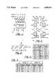
- FIG. 3is a simplified side view of an array of four radiating elements which may be used in the antenna system of the present invention, and which shows the spacing between the centers of the radiating elements;
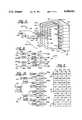
- FIG. 4is a view of a simplified perspective second example of a direct-radiating array antenna system of the present invention, which system has an array of 32 radiating elements arranged in a 4 ⁇ 8 planar matrix and constrained feed system for the array comprised of one row distribution and four column distribution networks;
- FIG. 5is a simplified front view showing the array of 32 radiating elements of the FIG. 4 array antenna system
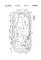
- FIG. 6is simplified view of the Continental United States showing its border, upon which is superimposed a graph of selected constant-gain contours of the beam coverage provided by the FIG. 4 antenna system;
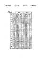
- FIG. 7is a table of array excitation values associated with the 32-element array of FIG. 5;
- FIG. 8is a detailed block diagram of the row distribution network for the FIG. 4 system.
- FIG. 9is a table of distribution parameters associated with the FIG. 8 network
- FIG. 10is a representative column distribution network of the FIG. 4 system.
- FIG. 11is a table of the distribution parameters of the FIG. 10 network.
- a dual mode array antenna system 20 of the present inventionwhich includes an array 22 of four radiating elements 24, 26, 28 and 30 and feed means 32.
- the elements 24-30may be of any suitable or conventional type, such as horns, dipoles, helices, spiral antennas, polyrods or parabolic dishes. The selection of the type of radiating element is not crucial to the present invention and such selection may be made based on the usual factors such as frequency band, weight, ruggedness, packaging and the like.
- Feed means 32is preferably a distribution network of the type which will be shortly described.
- the distribution network 32includes four ports 34, 36, 38 and 40 directly connected to the elements 24, 26, 28 and 30 as shown.
- Network 32also includes two ports 42 and 44, which serve as input ports A and B when the system 20 operates as a transmitting antenna (and which serve as output ports A and B when system 20 operates as a receiving antenna).
- FIG. 2shows a detailed circuit diagram of a preferred embodiment for the distribution network 32, which resembles but is not a four port Butler matrix, since it differs in construction and function from a Butler matrix.
- Network 32which is also sometimes referred to as a beam-forming network, includes four signal-dividing devices or directional couplers 52, 54, 56 and 58.
- Network 32also includes two phase-shifting devices 60 and 62.
- the devices 52-58are arranged in two stages 64 and 66 of two devices each.
- Conventional or suitable connecting lines 70 through 88are used as needed to provide essentially lossless interconnections between the various devices and ports within the network 32.
- connecting linemeans a passive electromagnetic signal-carrying device such as a conductor, waveguide, transmission strip line, or the like. Whether a connecting line is needed of course depends upon the precise type and lay-out of the distribution network and the location of the various devices within the lay-out. Such details are well within the skill of those in the art and thus need not be discussed. Similarly, connecting lines may be provided as necessary to provide interconnections for electromagnetic signals between the ports 34-40 and their respective feed elements 24-30.
- the signal-dividing devices 52-58 used within network 32 of FIG. 2are preferably hybrid couplers as shown.
- the hybrid couplersmay be of any conventional or suitable type designed for the frequency of the signals to be passed therethrough, such as the 3 dB variety with a 90 degree phase-lag between diagonal terminals.
- terminal 92 of coupler 52is not used, but instead is terminated by any suitable technique such as conventional resistive load 96.
- terminal 94 of coupler 54is not used, but instead is terminated by any suitable technique such as resistive load 98.
- phase-shifting devices 60 and 62are of the +90 degree (phase-lead) type when phase-lag hybrid couplers are employed in the network 32.
- the devices 60 and 62may be of any conventional type suitable for the frequency band of the signals passing therethrough.
- a first information-bearing input signal having an appropriate frequency center and bandwidthis applied to the port 42 (Input A).
- the distribution network 32distributes the signal so that a first set of four signals are produced at the output ports 34-40 of network 32 and excite the radiating elements 24-30 to produce a first set of four individual beams of electromagnetic radiation which propagate into space. These four beams may be called the Mode A individual beams, and can be mathematically described in part by a first set of excitation coefficients a 1 through a 4 .
- the network 32distributes the signal so that a second set of four signals are produced at the outputs 34-40 and excite the radiating elements 24-30 to produce a second set of four individual beams.
- These four beamsmay be called the Mode B individual beams, and can be mathematically described in part by a second set of excitation coefficients b 1 through b 4 .
- the two sets of four excitation coefficientsare shown for convenience above their respective output ports and radiating elements in FIG. 1.
- These two sets of four individual beamshave excitation coefficients that are mathematically orthogonal to one another, as will be further explained.
- the four individual beams of each set of beams emanating from feed elements 24-30combine in space to produce a composite electromagnetic beam.
- the first composite beam (the Mode A composite beam) produced by the four individual beams of the first setis electromagnetically distinct from and preferably orthogonal to the composite electromagnetic beam (the Mode B composite beam) produced by the four individual beams of the second set.
- One important aspect and advantage of the array antenna system of the present inventionis its ability to produce two composite beams of electromagnetic radiation which have identical (or substantially identical) radiation patterns for input signals of comparable frequency and bandwidth applied to the two input ports 42 and 44 of network 32.
- the system 20is particularly advantageous since it has two input ports 42 and 44, and for any given signal applied to these ports, the resulting composite beams will have identical far-field radiation patterns.
- This two port featureoffers important implications in the channel multiplexing of channelized communication systems, since input signals for the odd-numbered channels may be run into one input port, while the input signals for the even-numbered signals may run into the other input port.
- This arrangementrequires multiplexing equipment which is simpler than a contiguous multiplexer operating with a one input port, single mode array antenna, and which is also simpler than odd and even multiplexers operating with two single mode arrays.
- Mode Ais the mode produced by the signal applied to input port A.
- Mode Bis the mode produced by the signal applied to input port B.
- the excitation coefficients for Mode Bare the mirror image of those for Mode A, in other words, when the following conditions are satisfied:
- the distribution network 32 shown in FIG. 2satisfies the conditions of Equations 9 and 10.
- the array factor for the two modescan be readily determined from the array geometry shown in FIG. 3.
- the array factoris
- Equation 11the symbol u is the normalized antenna parameter whose value is given by the following formula:
- ⁇is the signal wavelength
- ⁇is the beam scan angle as shown in FIG. 3
- dis the spacing between the radiating elements. Since the far-field radiation pattern for a composite beam produced by an array of equispaced radiators is proportional to the magnitude squared of the array factor, both Modes A and B will have the same far-field radiation pattern.
- FIG. 4shows a dual mode array antenna system 120 which has a planar array 122 of 32 contiguous radiating elements configured in a rectangular or matrix arrangement of four columns C1-C4 by eight rows R1-R8, as best shown in FIG. 5.
- the array 122is driven by a constrained feed system 124 which is comprised of a first or horizontal distribution network 126 and a group or set 128 of four second or vertical distribution networks 130-136.
- the horizontal distribution network 126is connected by connecting lines 140 through 146 to the input ports 150-156 of networks 130-136.
- the vertical distribution networks 130-136are identical and each have a single input port and eight output ports which are connected to one column of radiating elements in the array 122.
- Vertical distribution network 130is typical, and has a single input port 150 and eight output ports 160 1 -160 8 , which are interconnected to the eight radiating elements of column C1 by connecting lines 170 1 -170 8 .
- the first distribution network 126has two input ports 176 and 178, and four output ports 180-186.
- FIG. 5A view of the front 190 of array 122 is shown in FIG. 5.
- Each of the elementsis a conventional waveguide pyramidal horn using vertical polarization. Each element is approximately 4.68 inches in height and 3.915 inches in width, which dimensions are also the distances between vertical and horizontal centers.
- the array antenna system 120is intended to provide substantially uniform (i.e., relatively constant gain) coverage for the Continental United States (i.e., the 48 contiguous states) from a communications satellite in geosynchronous orbit at a position at 83 degrees west longitude over the frequency range of 11.7 to 12.2 GHz.
- the array dimensionswere selected using well-known antenna design techniques applicable to single mode antenna designs.
- the resulting coverage beams from the arraywere generated using a conventional computer program of the type well-known in the art for simulating array antenna performance.
- the beams for Modes A and Bare identical to each other and to the beam pattern shown by the constant-gain curves or contours in FIG. 6.
- the pattern shown in FIG. 6is a composite or average over three frequencies (11.7, 11.95 and 12.2 GHz). Since the patterns for Mode A and Mode B are identical to each other, those in the art will appreciate that antenna system 120 of FIG. 4 provides dual mode coverage gain over the intended area comparable to that expected of single mode array antenna system designs.
- FIG. 4provides dual mode coverage gain over the intended area comparable to that expected of single mode array antenna system designs.
- the outline of the Continental United Statesis indicated by heavy line 200
- the vertical and horizontal centers of the bore sight of antenna system 120are indicated by dotted lines 201 and 202
- the constant gain contours (in decibels) corresponding to 25.0 dB, 26.0 dB, 27.0 dB, 28.0 dB and 29.0 dBare indicated respectively by lines 205, 206, 207, 208 and 209.
- the two constant gain contours corresponding to 30.0 dBare indicated by lines 210 and 211.
- the western and eastern locations of the maximum gain of 30.84 dBare indicated by crosses 214 and 215.
- the array excitations for array 122are listed in the table of FIG. 7. Specifically, the table lists relative power and relative phase for each element or horn for both Modes A and B.
- the excitations listed in FIG. 7were generated by a conventional computer program which uses a standard iterative search technique that seeks to optimize the antenna gain over the coverage region of interest for both Modes, while simultaneously requiring that the element excitations for the two Modes be orthogonal, that is satisfy Equation 2 above.
- the contents of the FIG. 7 tableare the results produced by one such iterative search program.
- each row or horizontal group of four elements of the array 122operates in a dual mode fashion and has the same dual mode parameters.
- element H1gets 37.10% of the power in the first row R1
- element H5gets 37.10% of the power in the second row R2
- element H9gets 37.10% of the power in the third row R3, etc.
- the relative distribution of power and the relative phaseis the same as in every other row.
- Some rowsget more total power than other rows, but within each row the relative power distribution among the elements of that row is the same. This is also true for phase shifts (which are expressed in degrees in the table).
- the array 122is dual mode in the azimuth direction and conventional or single mode in the elevation direction.
- the overall distribution network 124 to provide the array excitationsmay consist of one dual mode two-to-four row network 126, followed by four column distribution networks 130-136. This is the arrangement previously shown in FIG. 4. Those skilled in the art will realize that a complimentary distribution may also be used, namely two column distribution networks followed by eight two-to-four horizontal distribution networks. However this latter arrangement actually contains more couplers than the arrangement shown in FIG. 4, and thus the simpler FIG. 4 implementation is preferred.
- the various connecting lines 240-262, between input terminals 176 and 178, couplers 222-228, phase shifters 230 and 232, and output terminals 180-186,provide essentially lossless interconnections between various devices and ports within the network 126.
- Each coupler 222-228has its cross-coupling value (either 0.3340 or 0.4430) listed therein, and imparts a -90 degrees phase shift to the cross-coupled signal passing therethrough.
- a signal entering the first coupler 222will have 33.40% of its power coupled to line 242, which signal is then distributed by coupler 228 to output ports 180 and 182.
- the coupler 222also imparts a -90 degrees phase shift to this coupled signal passed to line 242.
- the direct output of the first coupler 222 on line 240will have 66.6% (100-33.40) of the power of signal A.
- Coupler 222imparts no phase shift (0 degrees) to the portion of signal A delivered to this direct or uncoupled output connected to line 240.
- the distribution parameters for the two-to-four network 126 of FIG. 8are presented in the table shown in FIG. 9. This table indicates the fractional power and net phase shift for each path through the network 126.
- FIG. 10A preferred construction for a typical column distribution network, namely representative network 130, is shown in FIG. 10.
- Network 130has a standard corporate feed structure composed of seven directional couplers 270-282 and has eight phase shifters 284-298.
- the directional couplers 270-282function in the same general manner as the couplers shown in FIG. 8, and the cross-coupling values for each coupler is shown therein in FIG. 10.
- the phase shift values (in degrees) of each phase shifter 284-298are shown therein.
- the distribution parameters of the FIG. 10 networkthat is relative power and relative phase between the inputs 150 and the outputs 160 1 -160 8 , are indicated in the table shown in FIG. 11.
- Suitable termination devices, such as device 300are provided at the unused input port of each of the directional couplers 270-282.
- Networks 126 and 130-136, and all of the connecting lines and terminating loads used therewith,may be fabricated using conventional microwave components well-known to those in the antenna art, such as waveguide or TEM (transverse electromagnetic mode) line components.
- the antenna array system 120 illustrated in FIGS. 4-11is dual mode in one dimension (the row or horizontal direction, which corresponds to the azimuth direction parallel to dotted line 202 in FIG. 6), and single mode in the other dimension (the column or vertical direction, corresponding to the elevation direction parallel to dotted line 201 in FIG. 6).
- the present invention as described abovemay be readily extended to an array of radiating elements which is dual mode in both dimensions (azimuth and elevation).
- Such an antenna array systemwould have four modes, two in each dimension.
- having dual mode in both dimensionsviolates no fundamental principles, and may be implemented by simply extending the computations required in conjunction with Equation 2 from one dimension to two dimensions. In such a case, the array would have four composite beams having the same (or substantially the same) far-field coverage or beam pattern.
- array antenna systems 20 and 120While the foregoing discussion of array antenna systems 20 and 120 has primarily described these two systems as transmitting systems, those skilled in the art will readily appreciate that each of the systems will also function quite nicely as a receiving antenna system as well.
- the antenna system 20When the antenna system 20 is used for example, as a receiver, the first ports 34-40 of network 32 become input ports while ports 42 and 44 become output ports.
- the network 32then functions as a means for separating the composite beams received by the elements 24-30 into two distinct signals which are effectively routed to either output port 42 or output port 44, since the network is fully reciprocal. Since network 32 as shown in FIG. 2 is constructed of only passive devices, it is reciprocal and lossless, and all of the principles of operation explained earlier apply to the system 20 as a receiving antenna system.
- FIGS. 4-11the same type of comments may be made about array antenna system 120 shown in FIGS. 4-11.
- dual mode antenna systems of the present inventioncan be readily constructed from existing, well-developed and understood microwave components organized in the general form of familiar constrained feed structures. No new component devices need to be developed or perfected to implement the antenna systems of the present invention.
- Another advantage of the antenna systems of the present inventionis that they do not require a reflector, as do the dual mode antenna systems described in the aforementioned U.S. Pat. Nos. 3,668,567 and 4,117,423.
- the dual mode antenna systems of the present inventionwill likely have greatest utility in the microwave frequency ranges, that is frequencies in the range from 300 MHz to 30 GHz. Also, in a typical application for our dual mode antenna systems the first and second information-bearing signals will occupy the same general frequency range, but this is not required.
Landscapes
- Variable-Direction Aerials And Aerial Arrays (AREA)
Abstract
Description
A.sub.i =x.sub.a a.sub.i +x.sub.b b.sub.i +x.sub.c c.sub.i +. . .+x.sub.m z.sub.i ( 3)
B.sub.i =y.sub.a a.sub.i +y.sub.b b.sub.i +y.sub.c c.sub.i +. . .+y.sub.m z.sub.i ( 4)
b.sub.1 =a.sub.4
b.sub.2 =a.sub.3 (5)
b.sub.3 =a.sub.2
b.sub.4 =a.sub.1
a.sub.1 a.sub.4 +a.sub.2 a.sub.3 =0 (7)
a.sub.1 /a.sub.2 =-a.sub.3 /a.sub.4 (8)
FOR Mode A: a.sub.1 =a.sub.2 =a.sub.3 =0.5 and a.sub.4 =-0.5(9)
FOR Mode B: b.sub.1 =-0.5 and b.sub.2 =b.sub.3 =b.sub.4 =0.5(10)
E.sub.A =0.5 (e.sup.ju +e.sup.-ju +e.sup.j3u -e.sup.-j3u) (11)
E.sub.A =COS(u)+j SIN (3u) (12)
E.sub.B =COS(u)-j SIN (3u) (13)
u=(πd SIN θ)/λ (14)
Claims (17)
Priority Applications (6)
| Application Number | Priority Date | Filing Date | Title |
|---|---|---|---|
| US07/111,909US4989011A (en) | 1987-10-23 | 1987-10-23 | Dual mode phased array antenna system |
| AU22177/88AAU602244B2 (en) | 1987-10-23 | 1988-09-13 | Dual mode phased array antenna system |
| CA000578152ACA1309172C (en) | 1987-10-23 | 1988-09-22 | Dual mode phased array antenna system |
| DE3855343TDE3855343T2 (en) | 1987-10-23 | 1988-10-21 | Phase controlled antenna system for two modes |
| EP88117526AEP0313057B1 (en) | 1987-10-23 | 1988-10-21 | Dual mode phased array antenna system |
| JP63265958AJP2585399B2 (en) | 1987-10-23 | 1988-10-21 | Dual mode phased array antenna system |
Applications Claiming Priority (1)
| Application Number | Priority Date | Filing Date | Title |
|---|---|---|---|
| US07/111,909US4989011A (en) | 1987-10-23 | 1987-10-23 | Dual mode phased array antenna system |
Publications (1)
| Publication Number | Publication Date |
|---|---|
| US4989011Atrue US4989011A (en) | 1991-01-29 |
Family
ID=22341076
Family Applications (1)
| Application Number | Title | Priority Date | Filing Date |
|---|---|---|---|
| US07/111,909Expired - LifetimeUS4989011A (en) | 1987-10-23 | 1987-10-23 | Dual mode phased array antenna system |
Country Status (6)
| Country | Link |
|---|---|
| US (1) | US4989011A (en) |
| EP (1) | EP0313057B1 (en) |
| JP (1) | JP2585399B2 (en) |
| AU (1) | AU602244B2 (en) |
| CA (1) | CA1309172C (en) |
| DE (1) | DE3855343T2 (en) |
Cited By (149)
| Publication number | Priority date | Publication date | Assignee | Title |
|---|---|---|---|---|
| US5274839A (en)* | 1992-02-12 | 1993-12-28 | General Electric Co. | Satellite communications system with the zero-db coupler |
| US5717405A (en)* | 1996-07-17 | 1998-02-10 | Hughes Electronics | Four-port phase and amplitude equalizer for feed enhancement of wideband antenna arrays with low sum and difference sidelobes |
| US5812088A (en)* | 1994-12-19 | 1998-09-22 | Agence Spatiale Europeenne | Beam forming network for radiofrequency antennas |
| US6252562B1 (en)* | 1997-03-17 | 2001-06-26 | Centre National D'etudes Spatiales | Antenna for orbiting satellite |
| US6703974B2 (en) | 2002-03-20 | 2004-03-09 | The Boeing Company | Antenna system having active polarization correlation and associated method |
| US6992622B1 (en)* | 2004-10-15 | 2006-01-31 | Interdigital Technology Corporation | Wireless communication method and antenna system for determining direction of arrival information to form a three-dimensional beam used by a transceiver |
| RU2298267C1 (en)* | 2005-10-19 | 2007-04-27 | Открытое акционерное общество "Корпорация "Фазотрон - научно-исследовательский институт радиостроения" | Multibeam active phased antenna array |
| US20070215316A1 (en)* | 2004-01-26 | 2007-09-20 | Hitachi, Ltd. | Semiconductor Device |
| US20080291110A1 (en)* | 2007-05-24 | 2008-11-27 | Huawei Technologies Co., Ltd. | Feed Network Device, Antenna Feeder Subsystem, and Base Station System |
| RU2424607C2 (en)* | 2009-08-11 | 2011-07-20 | Открытое акционерное общество "Научно-производственное объединение "Лианозовский электромеханический завод" | Multi-beam receiving antenna |
| US20130321196A1 (en)* | 2010-12-29 | 2013-12-05 | Robert Bosch Gmbh | Radar sensor for motor vehicles |
| US9112255B1 (en)* | 2012-03-13 | 2015-08-18 | L-3 Communications Corp. | Radio frequency comparator waveguide system |
| CN106463817A (en)* | 2014-04-28 | 2017-02-22 | 瑞典爱立信有限公司 | An antenna arrangement with variable antenna pattern |
| US20170062950A1 (en)* | 2014-05-14 | 2017-03-02 | Huawei Technologies Co., Ltd. | Multi-beam antenna system and phase adjustment method for multi-beam antenna system, and dual-polarized antenna system |
| US9667317B2 (en) | 2015-06-15 | 2017-05-30 | At&T Intellectual Property I, L.P. | Method and apparatus for providing security using network traffic adjustments |
| US9674711B2 (en) | 2013-11-06 | 2017-06-06 | At&T Intellectual Property I, L.P. | Surface-wave communications and methods thereof |
| US9685992B2 (en) | 2014-10-03 | 2017-06-20 | At&T Intellectual Property I, L.P. | Circuit panel network and methods thereof |
| US9705610B2 (en) | 2014-10-21 | 2017-07-11 | At&T Intellectual Property I, L.P. | Transmission device with impairment compensation and methods for use therewith |
| US9705561B2 (en) | 2015-04-24 | 2017-07-11 | At&T Intellectual Property I, L.P. | Directional coupling device and methods for use therewith |
| US9722318B2 (en) | 2015-07-14 | 2017-08-01 | At&T Intellectual Property I, L.P. | Method and apparatus for coupling an antenna to a device |
| US9729197B2 (en) | 2015-10-01 | 2017-08-08 | At&T Intellectual Property I, L.P. | Method and apparatus for communicating network management traffic over a network |
| US9735833B2 (en) | 2015-07-31 | 2017-08-15 | At&T Intellectual Property I, L.P. | Method and apparatus for communications management in a neighborhood network |
| US9742521B2 (en) | 2014-11-20 | 2017-08-22 | At&T Intellectual Property I, L.P. | Transmission device with mode division multiplexing and methods for use therewith |
| US9742462B2 (en) | 2014-12-04 | 2017-08-22 | At&T Intellectual Property I, L.P. | Transmission medium and communication interfaces and methods for use therewith |
| US9749013B2 (en) | 2015-03-17 | 2017-08-29 | At&T Intellectual Property I, L.P. | Method and apparatus for reducing attenuation of electromagnetic waves guided by a transmission medium |
| US9749053B2 (en) | 2015-07-23 | 2017-08-29 | At&T Intellectual Property I, L.P. | Node device, repeater and methods for use therewith |
| US9748626B2 (en) | 2015-05-14 | 2017-08-29 | At&T Intellectual Property I, L.P. | Plurality of cables having different cross-sectional shapes which are bundled together to form a transmission medium |
| US9769128B2 (en) | 2015-09-28 | 2017-09-19 | At&T Intellectual Property I, L.P. | Method and apparatus for encryption of communications over a network |
| US9768833B2 (en) | 2014-09-15 | 2017-09-19 | At&T Intellectual Property I, L.P. | Method and apparatus for sensing a condition in a transmission medium of electromagnetic waves |
| US9769020B2 (en) | 2014-10-21 | 2017-09-19 | At&T Intellectual Property I, L.P. | Method and apparatus for responding to events affecting communications in a communication network |
| US9780834B2 (en) | 2014-10-21 | 2017-10-03 | At&T Intellectual Property I, L.P. | Method and apparatus for transmitting electromagnetic waves |
| US9787412B2 (en) | 2015-06-25 | 2017-10-10 | At&T Intellectual Property I, L.P. | Methods and apparatus for inducing a fundamental wave mode on a transmission medium |
| US9793954B2 (en) | 2015-04-28 | 2017-10-17 | At&T Intellectual Property I, L.P. | Magnetic coupling device and methods for use therewith |
| US9793955B2 (en) | 2015-04-24 | 2017-10-17 | At&T Intellectual Property I, Lp | Passive electrical coupling device and methods for use therewith |
| US9793951B2 (en) | 2015-07-15 | 2017-10-17 | At&T Intellectual Property I, L.P. | Method and apparatus for launching a wave mode that mitigates interference |
| US9800327B2 (en) | 2014-11-20 | 2017-10-24 | At&T Intellectual Property I, L.P. | Apparatus for controlling operations of a communication device and methods thereof |
| US9820146B2 (en) | 2015-06-12 | 2017-11-14 | At&T Intellectual Property I, L.P. | Method and apparatus for authentication and identity management of communicating devices |
| US9838078B2 (en) | 2015-07-31 | 2017-12-05 | At&T Intellectual Property I, L.P. | Method and apparatus for exchanging communication signals |
| US9838896B1 (en) | 2016-12-09 | 2017-12-05 | At&T Intellectual Property I, L.P. | Method and apparatus for assessing network coverage |
| US9847850B2 (en) | 2014-10-14 | 2017-12-19 | At&T Intellectual Property I, L.P. | Method and apparatus for adjusting a mode of communication in a communication network |
| US9847566B2 (en) | 2015-07-14 | 2017-12-19 | At&T Intellectual Property I, L.P. | Method and apparatus for adjusting a field of a signal to mitigate interference |
| US9853342B2 (en) | 2015-07-14 | 2017-12-26 | At&T Intellectual Property I, L.P. | Dielectric transmission medium connector and methods for use therewith |
| US9860075B1 (en) | 2016-08-26 | 2018-01-02 | At&T Intellectual Property I, L.P. | Method and communication node for broadband distribution |
| US9866276B2 (en) | 2014-10-10 | 2018-01-09 | At&T Intellectual Property I, L.P. | Method and apparatus for arranging communication sessions in a communication system |
| US9865911B2 (en) | 2015-06-25 | 2018-01-09 | At&T Intellectual Property I, L.P. | Waveguide system for slot radiating first electromagnetic waves that are combined into a non-fundamental wave mode second electromagnetic wave on a transmission medium |
| US9866309B2 (en) | 2015-06-03 | 2018-01-09 | At&T Intellectual Property I, Lp | Host node device and methods for use therewith |
| US9871282B2 (en) | 2015-05-14 | 2018-01-16 | At&T Intellectual Property I, L.P. | At least one transmission medium having a dielectric surface that is covered at least in part by a second dielectric |
| US9871283B2 (en) | 2015-07-23 | 2018-01-16 | At&T Intellectual Property I, Lp | Transmission medium having a dielectric core comprised of plural members connected by a ball and socket configuration |
| US9871558B2 (en) | 2014-10-21 | 2018-01-16 | At&T Intellectual Property I, L.P. | Guided-wave transmission device and methods for use therewith |
| US9876571B2 (en) | 2015-02-20 | 2018-01-23 | At&T Intellectual Property I, Lp | Guided-wave transmission device with non-fundamental mode propagation and methods for use therewith |
| US9876264B2 (en) | 2015-10-02 | 2018-01-23 | At&T Intellectual Property I, Lp | Communication system, guided wave switch and methods for use therewith |
| US9876605B1 (en) | 2016-10-21 | 2018-01-23 | At&T Intellectual Property I, L.P. | Launcher and coupling system to support desired guided wave mode |
| US9882257B2 (en) | 2015-07-14 | 2018-01-30 | At&T Intellectual Property I, L.P. | Method and apparatus for launching a wave mode that mitigates interference |
| US9887447B2 (en) | 2015-05-14 | 2018-02-06 | At&T Intellectual Property I, L.P. | Transmission medium having multiple cores and methods for use therewith |
| US9893795B1 (en) | 2016-12-07 | 2018-02-13 | At&T Intellectual Property I, Lp | Method and repeater for broadband distribution |
| US9906269B2 (en) | 2014-09-17 | 2018-02-27 | At&T Intellectual Property I, L.P. | Monitoring and mitigating conditions in a communication network |
| US9904535B2 (en) | 2015-09-14 | 2018-02-27 | At&T Intellectual Property I, L.P. | Method and apparatus for distributing software |
| US9912027B2 (en) | 2015-07-23 | 2018-03-06 | At&T Intellectual Property I, L.P. | Method and apparatus for exchanging communication signals |
| US9912381B2 (en) | 2015-06-03 | 2018-03-06 | At&T Intellectual Property I, Lp | Network termination and methods for use therewith |
| US9913139B2 (en) | 2015-06-09 | 2018-03-06 | At&T Intellectual Property I, L.P. | Signal fingerprinting for authentication of communicating devices |
| US9912033B2 (en) | 2014-10-21 | 2018-03-06 | At&T Intellectual Property I, Lp | Guided wave coupler, coupling module and methods for use therewith |
| US9911020B1 (en) | 2016-12-08 | 2018-03-06 | At&T Intellectual Property I, L.P. | Method and apparatus for tracking via a radio frequency identification device |
| US9917341B2 (en) | 2015-05-27 | 2018-03-13 | At&T Intellectual Property I, L.P. | Apparatus and method for launching electromagnetic waves and for modifying radial dimensions of the propagating electromagnetic waves |
| US9929755B2 (en) | 2015-07-14 | 2018-03-27 | At&T Intellectual Property I, L.P. | Method and apparatus for coupling an antenna to a device |
| US9927517B1 (en) | 2016-12-06 | 2018-03-27 | At&T Intellectual Property I, L.P. | Apparatus and methods for sensing rainfall |
| US9948333B2 (en) | 2015-07-23 | 2018-04-17 | At&T Intellectual Property I, L.P. | Method and apparatus for wireless communications to mitigate interference |
| US9954286B2 (en) | 2014-10-21 | 2018-04-24 | At&T Intellectual Property I, L.P. | Guided-wave transmission device with non-fundamental mode propagation and methods for use therewith |
| US9954287B2 (en) | 2014-11-20 | 2018-04-24 | At&T Intellectual Property I, L.P. | Apparatus for converting wireless signals and electromagnetic waves and methods thereof |
| US9967173B2 (en) | 2015-07-31 | 2018-05-08 | At&T Intellectual Property I, L.P. | Method and apparatus for authentication and identity management of communicating devices |
| US9973940B1 (en) | 2017-02-27 | 2018-05-15 | At&T Intellectual Property I, L.P. | Apparatus and methods for dynamic impedance matching of a guided wave launcher |
| US9973416B2 (en) | 2014-10-02 | 2018-05-15 | At&T Intellectual Property I, L.P. | Method and apparatus that provides fault tolerance in a communication network |
| US9991580B2 (en) | 2016-10-21 | 2018-06-05 | At&T Intellectual Property I, L.P. | Launcher and coupling system for guided wave mode cancellation |
| US9999038B2 (en) | 2013-05-31 | 2018-06-12 | At&T Intellectual Property I, L.P. | Remote distributed antenna system |
| US9998870B1 (en) | 2016-12-08 | 2018-06-12 | At&T Intellectual Property I, L.P. | Method and apparatus for proximity sensing |
| US9997819B2 (en) | 2015-06-09 | 2018-06-12 | At&T Intellectual Property I, L.P. | Transmission medium and method for facilitating propagation of electromagnetic waves via a core |
| US10009067B2 (en) | 2014-12-04 | 2018-06-26 | At&T Intellectual Property I, L.P. | Method and apparatus for configuring a communication interface |
| US10020844B2 (en) | 2016-12-06 | 2018-07-10 | T&T Intellectual Property I, L.P. | Method and apparatus for broadcast communication via guided waves |
| US10027397B2 (en) | 2016-12-07 | 2018-07-17 | At&T Intellectual Property I, L.P. | Distributed antenna system and methods for use therewith |
| US10033107B2 (en) | 2015-07-14 | 2018-07-24 | At&T Intellectual Property I, L.P. | Method and apparatus for coupling an antenna to a device |
| US10033108B2 (en) | 2015-07-14 | 2018-07-24 | At&T Intellectual Property I, L.P. | Apparatus and methods for generating an electromagnetic wave having a wave mode that mitigates interference |
| US10044409B2 (en) | 2015-07-14 | 2018-08-07 | At&T Intellectual Property I, L.P. | Transmission medium and methods for use therewith |
| US10051630B2 (en) | 2013-05-31 | 2018-08-14 | At&T Intellectual Property I, L.P. | Remote distributed antenna system |
| US10069185B2 (en) | 2015-06-25 | 2018-09-04 | At&T Intellectual Property I, L.P. | Methods and apparatus for inducing a non-fundamental wave mode on a transmission medium |
| US10067172B1 (en)* | 2016-07-21 | 2018-09-04 | Softronics, Ltd. | Far-field antenna pattern characterization via drone/UAS platform |
| US10069535B2 (en) | 2016-12-08 | 2018-09-04 | At&T Intellectual Property I, L.P. | Apparatus and methods for launching electromagnetic waves having a certain electric field structure |
| US10090594B2 (en) | 2016-11-23 | 2018-10-02 | At&T Intellectual Property I, L.P. | Antenna system having structural configurations for assembly |
| US10090606B2 (en) | 2015-07-15 | 2018-10-02 | At&T Intellectual Property I, L.P. | Antenna system with dielectric array and methods for use therewith |
| US10103422B2 (en) | 2016-12-08 | 2018-10-16 | At&T Intellectual Property I, L.P. | Method and apparatus for mounting network devices |
| US10129057B2 (en) | 2015-07-14 | 2018-11-13 | At&T Intellectual Property I, L.P. | Apparatus and methods for inducing electromagnetic waves on a cable |
| US10135146B2 (en) | 2016-10-18 | 2018-11-20 | At&T Intellectual Property I, L.P. | Apparatus and methods for launching guided waves via circuits |
| US10135147B2 (en) | 2016-10-18 | 2018-11-20 | At&T Intellectual Property I, L.P. | Apparatus and methods for launching guided waves via an antenna |
| US10135145B2 (en) | 2016-12-06 | 2018-11-20 | At&T Intellectual Property I, L.P. | Apparatus and methods for generating an electromagnetic wave along a transmission medium |
| US10139820B2 (en) | 2016-12-07 | 2018-11-27 | At&T Intellectual Property I, L.P. | Method and apparatus for deploying equipment of a communication system |
| US10148016B2 (en) | 2015-07-14 | 2018-12-04 | At&T Intellectual Property I, L.P. | Apparatus and methods for communicating utilizing an antenna array |
| US10170840B2 (en) | 2015-07-14 | 2019-01-01 | At&T Intellectual Property I, L.P. | Apparatus and methods for sending or receiving electromagnetic signals |
| US10168695B2 (en) | 2016-12-07 | 2019-01-01 | At&T Intellectual Property I, L.P. | Method and apparatus for controlling an unmanned aircraft |
| US10178445B2 (en) | 2016-11-23 | 2019-01-08 | At&T Intellectual Property I, L.P. | Methods, devices, and systems for load balancing between a plurality of waveguides |
| US10205655B2 (en) | 2015-07-14 | 2019-02-12 | At&T Intellectual Property I, L.P. | Apparatus and methods for communicating utilizing an antenna array and multiple communication paths |
| US10224634B2 (en) | 2016-11-03 | 2019-03-05 | At&T Intellectual Property I, L.P. | Methods and apparatus for adjusting an operational characteristic of an antenna |
| US10225025B2 (en) | 2016-11-03 | 2019-03-05 | At&T Intellectual Property I, L.P. | Method and apparatus for detecting a fault in a communication system |
| US10243270B2 (en) | 2016-12-07 | 2019-03-26 | At&T Intellectual Property I, L.P. | Beam adaptive multi-feed dielectric antenna system and methods for use therewith |
| US10243784B2 (en) | 2014-11-20 | 2019-03-26 | At&T Intellectual Property I, L.P. | System for generating topology information and methods thereof |
| US10264586B2 (en) | 2016-12-09 | 2019-04-16 | At&T Mobility Ii Llc | Cloud-based packet controller and methods for use therewith |
| US10291334B2 (en) | 2016-11-03 | 2019-05-14 | At&T Intellectual Property I, L.P. | System for detecting a fault in a communication system |
| US10298293B2 (en) | 2017-03-13 | 2019-05-21 | At&T Intellectual Property I, L.P. | Apparatus of communication utilizing wireless network devices |
| US10305190B2 (en) | 2016-12-01 | 2019-05-28 | At&T Intellectual Property I, L.P. | Reflecting dielectric antenna system and methods for use therewith |
| US10312567B2 (en) | 2016-10-26 | 2019-06-04 | At&T Intellectual Property I, L.P. | Launcher with planar strip antenna and methods for use therewith |
| US10320586B2 (en) | 2015-07-14 | 2019-06-11 | At&T Intellectual Property I, L.P. | Apparatus and methods for generating non-interfering electromagnetic waves on an insulated transmission medium |
| US10326689B2 (en) | 2016-12-08 | 2019-06-18 | At&T Intellectual Property I, L.P. | Method and system for providing alternative communication paths |
| US10326494B2 (en) | 2016-12-06 | 2019-06-18 | At&T Intellectual Property I, L.P. | Apparatus for measurement de-embedding and methods for use therewith |
| US10340600B2 (en) | 2016-10-18 | 2019-07-02 | At&T Intellectual Property I, L.P. | Apparatus and methods for launching guided waves via plural waveguide systems |
| US10340601B2 (en) | 2016-11-23 | 2019-07-02 | At&T Intellectual Property I, L.P. | Multi-antenna system and methods for use therewith |
| US10340603B2 (en) | 2016-11-23 | 2019-07-02 | At&T Intellectual Property I, L.P. | Antenna system having shielded structural configurations for assembly |
| US10341142B2 (en) | 2015-07-14 | 2019-07-02 | At&T Intellectual Property I, L.P. | Apparatus and methods for generating non-interfering electromagnetic waves on an uninsulated conductor |
| US10340573B2 (en) | 2016-10-26 | 2019-07-02 | At&T Intellectual Property I, L.P. | Launcher with cylindrical coupling device and methods for use therewith |
| US10340983B2 (en) | 2016-12-09 | 2019-07-02 | At&T Intellectual Property I, L.P. | Method and apparatus for surveying remote sites via guided wave communications |
| US10355367B2 (en) | 2015-10-16 | 2019-07-16 | At&T Intellectual Property I, L.P. | Antenna structure for exchanging wireless signals |
| US10359749B2 (en) | 2016-12-07 | 2019-07-23 | At&T Intellectual Property I, L.P. | Method and apparatus for utilities management via guided wave communication |
| US10361489B2 (en) | 2016-12-01 | 2019-07-23 | At&T Intellectual Property I, L.P. | Dielectric dish antenna system and methods for use therewith |
| US10374316B2 (en) | 2016-10-21 | 2019-08-06 | At&T Intellectual Property I, L.P. | System and dielectric antenna with non-uniform dielectric |
| US10382976B2 (en) | 2016-12-06 | 2019-08-13 | At&T Intellectual Property I, L.P. | Method and apparatus for managing wireless communications based on communication paths and network device positions |
| US10389029B2 (en) | 2016-12-07 | 2019-08-20 | At&T Intellectual Property I, L.P. | Multi-feed dielectric antenna system with core selection and methods for use therewith |
| US10389037B2 (en) | 2016-12-08 | 2019-08-20 | At&T Intellectual Property I, L.P. | Apparatus and methods for selecting sections of an antenna array and use therewith |
| US10411356B2 (en) | 2016-12-08 | 2019-09-10 | At&T Intellectual Property I, L.P. | Apparatus and methods for selectively targeting communication devices with an antenna array |
| US10439290B2 (en) | 2015-07-14 | 2019-10-08 | At&T Intellectual Property I, L.P. | Apparatus and methods for wireless communications |
| US10439675B2 (en) | 2016-12-06 | 2019-10-08 | At&T Intellectual Property I, L.P. | Method and apparatus for repeating guided wave communication signals |
| US10446936B2 (en) | 2016-12-07 | 2019-10-15 | At&T Intellectual Property I, L.P. | Multi-feed dielectric antenna system and methods for use therewith |
| US10498044B2 (en) | 2016-11-03 | 2019-12-03 | At&T Intellectual Property I, L.P. | Apparatus for configuring a surface of an antenna |
| US10511346B2 (en) | 2015-07-14 | 2019-12-17 | At&T Intellectual Property I, L.P. | Apparatus and methods for inducing electromagnetic waves on an uninsulated conductor |
| US10530505B2 (en) | 2016-12-08 | 2020-01-07 | At&T Intellectual Property I, L.P. | Apparatus and methods for launching electromagnetic waves along a transmission medium |
| US10535928B2 (en) | 2016-11-23 | 2020-01-14 | At&T Intellectual Property I, L.P. | Antenna system and methods for use therewith |
| US10547348B2 (en) | 2016-12-07 | 2020-01-28 | At&T Intellectual Property I, L.P. | Method and apparatus for switching transmission mediums in a communication system |
| US10601494B2 (en) | 2016-12-08 | 2020-03-24 | At&T Intellectual Property I, L.P. | Dual-band communication device and method for use therewith |
| US10637149B2 (en) | 2016-12-06 | 2020-04-28 | At&T Intellectual Property I, L.P. | Injection molded dielectric antenna and methods for use therewith |
| US10650940B2 (en) | 2015-05-15 | 2020-05-12 | At&T Intellectual Property I, L.P. | Transmission medium having a conductive material and methods for use therewith |
| US10694379B2 (en) | 2016-12-06 | 2020-06-23 | At&T Intellectual Property I, L.P. | Waveguide system with device-based authentication and methods for use therewith |
| US10727599B2 (en) | 2016-12-06 | 2020-07-28 | At&T Intellectual Property I, L.P. | Launcher with slot antenna and methods for use therewith |
| US10755542B2 (en) | 2016-12-06 | 2020-08-25 | At&T Intellectual Property I, L.P. | Method and apparatus for surveillance via guided wave communication |
| US10777873B2 (en) | 2016-12-08 | 2020-09-15 | At&T Intellectual Property I, L.P. | Method and apparatus for mounting network devices |
| US20200295799A1 (en)* | 2013-09-06 | 2020-09-17 | John Howard | Random, sequential, or simultaneous multi-beam circular antenna array and beam forming networks with up to 360° coverage |
| US10790593B2 (en) | 2015-07-14 | 2020-09-29 | At&T Intellectual Property I, L.P. | Method and apparatus including an antenna comprising a lens and a body coupled to a feedline having a structure that reduces reflections of electromagnetic waves |
| US10797781B2 (en) | 2015-06-03 | 2020-10-06 | At&T Intellectual Property I, L.P. | Client node device and methods for use therewith |
| US10811767B2 (en) | 2016-10-21 | 2020-10-20 | At&T Intellectual Property I, L.P. | System and dielectric antenna with convex dielectric radome |
| US10819035B2 (en) | 2016-12-06 | 2020-10-27 | At&T Intellectual Property I, L.P. | Launcher with helical antenna and methods for use therewith |
| US20200411971A1 (en)* | 2019-06-27 | 2020-12-31 | Thales | Two-dimensional analogue multibeam former of reduced complexity for reconfigurable active array antennas |
| US10916969B2 (en) | 2016-12-08 | 2021-02-09 | At&T Intellectual Property I, L.P. | Method and apparatus for providing power using an inductive coupling |
| US10938108B2 (en) | 2016-12-08 | 2021-03-02 | At&T Intellectual Property I, L.P. | Frequency selective multi-feed dielectric antenna system and methods for use therewith |
| US20220320730A1 (en)* | 2019-09-25 | 2022-10-06 | Sony Semiconductor Solutions Corporation | Antenna device |
| US20230036249A1 (en)* | 2019-12-19 | 2023-02-02 | Airbus Defence And Space Limited | Multibeam antenna |
Families Citing this family (6)
| Publication number | Priority date | Publication date | Assignee | Title |
|---|---|---|---|---|
| IT1244907B (en)* | 1991-01-23 | 1994-09-13 | Selenia Spazio Spa Ora Alenia | CONFIGURATION AND TECHNIQUE OF MULTIMODAL BAND FORMING NETS FOR MULTI-BAND REFLECTIVE ANTENNAS. |
| FR2732163B1 (en)* | 1995-03-20 | 1997-05-30 | Europ Agence Spatiale | DEVICE FOR SUPPLYING A MULTI-SOURCE AND MULTI-BEAM ANTENNA |
| GB0611379D0 (en) | 2006-06-09 | 2006-07-19 | Qinetiq Ltd | Phased array antenna system with two-dimensional scanning |
| EP3017506A1 (en)* | 2013-07-04 | 2016-05-11 | Telefonaktiebolaget LM Ericsson (publ) | A multi-beam antenna arrangement |
| US20160315386A1 (en)* | 2015-04-21 | 2016-10-27 | Huawei Technologies Co., Ltd. | Sparse Phase-Mode Planar Feed for Circular Arrays |
| US10432273B1 (en)* | 2018-04-12 | 2019-10-01 | Telefonaktiebolaget Lm Ericsson (Publ) | Antenna arrangement for transmitting reference signals |
Citations (11)
| Publication number | Priority date | Publication date | Assignee | Title |
|---|---|---|---|---|
| US3668567A (en)* | 1970-07-02 | 1972-06-06 | Hughes Aircraft Co | Dual mode rotary microwave coupler |
| US4117423A (en)* | 1976-09-23 | 1978-09-26 | Hughes Aircraft Company | Dual mode multiphase power divider |
| US4231040A (en)* | 1978-12-11 | 1980-10-28 | Motorola, Inc. | Simultaneous multiple beam antenna array matrix and method thereof |
| US4424500A (en)* | 1980-12-29 | 1984-01-03 | Sperry Corporation | Beam forming network for a multibeam antenna |
| US4499471A (en)* | 1983-05-02 | 1985-02-12 | Ford Aerospace & Communications Corporation | Reconfigurable dual mode network |
| US4503434A (en)* | 1983-05-02 | 1985-03-05 | Ford Aerospace & Communications Corporation | Lossless arbitrary output dual mode network |
| US4517568A (en)* | 1982-02-09 | 1985-05-14 | The United States Of America As Represented By The Secretary Of The Air Force | Angle set-on apparatus |
| US4584581A (en)* | 1981-10-27 | 1986-04-22 | Radio Research Laboratories, Ministry Of Posts And Telecommunications | Beam forming network for multibeam array antenna |
| US4584582A (en)* | 1981-08-31 | 1986-04-22 | Motorola, Inc. | Multi-mode direction finding antenna |
| US4638317A (en)* | 1984-06-19 | 1987-01-20 | Westinghouse Electric Corp. | Orthogonal beam forming network |
| US4689627A (en)* | 1983-05-20 | 1987-08-25 | Hughes Aircraft Company | Dual band phased antenna array using wideband element with diplexer |
Family Cites Families (5)
| Publication number | Priority date | Publication date | Assignee | Title |
|---|---|---|---|---|
| US4245223A (en)* | 1977-05-02 | 1981-01-13 | The United States Of America As Represented By The Secretary Of The Navy | Self-multiplexing antenna employing orthogonal beams |
| US4213132A (en)* | 1978-07-19 | 1980-07-15 | Motorola, Inc. | Antenna system with multiple frequency inputs |
| BE901351R (en)* | 1984-12-21 | 1985-06-21 | Itt Ind Belgium | Phase-shift antenna system - has four direct links between input and output hybrid couplers eliminating interstage delay |
| EP0294413B1 (en)* | 1986-12-22 | 1993-11-10 | Hughes Aircraft Company | Steerable beam antenna system using butler matrix |
| WO1988007439A1 (en)* | 1987-03-27 | 1988-10-06 | Nauchno-Proizvodstvennoe Obiedinenie Po Tekhnologi | Executing mechanism of manipulator |
- 1987
- 1987-10-23USUS07/111,909patent/US4989011A/ennot_activeExpired - Lifetime
- 1988
- 1988-09-13AUAU22177/88Apatent/AU602244B2/ennot_activeCeased
- 1988-09-22CACA000578152Apatent/CA1309172C/ennot_activeExpired - Lifetime
- 1988-10-21JPJP63265958Apatent/JP2585399B2/ennot_activeExpired - Lifetime
- 1988-10-21EPEP88117526Apatent/EP0313057B1/ennot_activeExpired - Lifetime
- 1988-10-21DEDE3855343Tpatent/DE3855343T2/ennot_activeExpired - Lifetime
Patent Citations (11)
| Publication number | Priority date | Publication date | Assignee | Title |
|---|---|---|---|---|
| US3668567A (en)* | 1970-07-02 | 1972-06-06 | Hughes Aircraft Co | Dual mode rotary microwave coupler |
| US4117423A (en)* | 1976-09-23 | 1978-09-26 | Hughes Aircraft Company | Dual mode multiphase power divider |
| US4231040A (en)* | 1978-12-11 | 1980-10-28 | Motorola, Inc. | Simultaneous multiple beam antenna array matrix and method thereof |
| US4424500A (en)* | 1980-12-29 | 1984-01-03 | Sperry Corporation | Beam forming network for a multibeam antenna |
| US4584582A (en)* | 1981-08-31 | 1986-04-22 | Motorola, Inc. | Multi-mode direction finding antenna |
| US4584581A (en)* | 1981-10-27 | 1986-04-22 | Radio Research Laboratories, Ministry Of Posts And Telecommunications | Beam forming network for multibeam array antenna |
| US4517568A (en)* | 1982-02-09 | 1985-05-14 | The United States Of America As Represented By The Secretary Of The Air Force | Angle set-on apparatus |
| US4499471A (en)* | 1983-05-02 | 1985-02-12 | Ford Aerospace & Communications Corporation | Reconfigurable dual mode network |
| US4503434A (en)* | 1983-05-02 | 1985-03-05 | Ford Aerospace & Communications Corporation | Lossless arbitrary output dual mode network |
| US4689627A (en)* | 1983-05-20 | 1987-08-25 | Hughes Aircraft Company | Dual band phased antenna array using wideband element with diplexer |
| US4638317A (en)* | 1984-06-19 | 1987-01-20 | Westinghouse Electric Corp. | Orthogonal beam forming network |
Non-Patent Citations (4)
| Title |
|---|
| J. Allen, "A Theoretical Limitation on the Formation of Lossless Multiple Beams in Linear Arrays", IRE Transactions on Antennas & Propagation, vol. AP-9, pp. 350-352, (Jul. 1961). |
| J. Allen, A Theoretical Limitation on the Formation of Lossless Multiple Beams in Linear Arrays , IRE Transactions on Antennas & Propagation, vol. AP 9, pp. 350 352, (Jul. 1961).* |
| S. Stein, "On Cross Coupling in Multiple-Beam Antennas", IRE Transactions on Antennas & Propagation, vol. AP-10, pp. 548-557 (Sep. 1962). |
| S. Stein, On Cross Coupling in Multiple Beam Antennas , IRE Transactions on Antennas & Propagation, vol. AP 10, pp. 548 557 (Sep. 1962).* |
Cited By (190)
| Publication number | Priority date | Publication date | Assignee | Title |
|---|---|---|---|---|
| US5274839A (en)* | 1992-02-12 | 1993-12-28 | General Electric Co. | Satellite communications system with the zero-db coupler |
| US5812088A (en)* | 1994-12-19 | 1998-09-22 | Agence Spatiale Europeenne | Beam forming network for radiofrequency antennas |
| US5717405A (en)* | 1996-07-17 | 1998-02-10 | Hughes Electronics | Four-port phase and amplitude equalizer for feed enhancement of wideband antenna arrays with low sum and difference sidelobes |
| US6252562B1 (en)* | 1997-03-17 | 2001-06-26 | Centre National D'etudes Spatiales | Antenna for orbiting satellite |
| US6703974B2 (en) | 2002-03-20 | 2004-03-09 | The Boeing Company | Antenna system having active polarization correlation and associated method |
| US7579805B2 (en) | 2004-01-26 | 2009-08-25 | Hitachi, Ltd. | Semiconductor device |
| US20070215316A1 (en)* | 2004-01-26 | 2007-09-20 | Hitachi, Ltd. | Semiconductor Device |
| US20060114158A1 (en)* | 2004-10-15 | 2006-06-01 | Interdigital Technology Corporation | Wireless communication method and antenna system for determining direction of arrival information to form a three-dimensional beam used by a transceiver |
| WO2006044579A3 (en)* | 2004-10-15 | 2006-08-17 | Interdigital Tech Corp | Wireless communication method and antenna system for determining direction of arrival information |
| US7427953B2 (en) | 2004-10-15 | 2008-09-23 | Interdigital Technology Corporation | Wireless communication apparatus for determining direction of arrival information to form a three-dimensional beam used by a transceiver |
| US6992622B1 (en)* | 2004-10-15 | 2006-01-31 | Interdigital Technology Corporation | Wireless communication method and antenna system for determining direction of arrival information to form a three-dimensional beam used by a transceiver |
| US7705779B2 (en) | 2004-10-15 | 2010-04-27 | Interdigital Technology Corporation | Wireless communication apparatus for determining direction of arrival information to form a three-dimensional beam used by a transceiver |
| RU2298267C1 (en)* | 2005-10-19 | 2007-04-27 | Открытое акционерное общество "Корпорация "Фазотрон - научно-исследовательский институт радиостроения" | Multibeam active phased antenna array |
| US20080291110A1 (en)* | 2007-05-24 | 2008-11-27 | Huawei Technologies Co., Ltd. | Feed Network Device, Antenna Feeder Subsystem, and Base Station System |
| US7839235B2 (en)* | 2007-05-24 | 2010-11-23 | Huawei Technologies Co., Ltd. | Feed network device, antenna feeder subsystem, and base station system |
| RU2424607C2 (en)* | 2009-08-11 | 2011-07-20 | Открытое акционерное общество "Научно-производственное объединение "Лианозовский электромеханический завод" | Multi-beam receiving antenna |
| US9638796B2 (en)* | 2010-12-29 | 2017-05-02 | Robert Bosch Gmbh | Radar sensor for motor vehicles |
| US20130321196A1 (en)* | 2010-12-29 | 2013-12-05 | Robert Bosch Gmbh | Radar sensor for motor vehicles |
| US9112255B1 (en)* | 2012-03-13 | 2015-08-18 | L-3 Communications Corp. | Radio frequency comparator waveguide system |
| US9999038B2 (en) | 2013-05-31 | 2018-06-12 | At&T Intellectual Property I, L.P. | Remote distributed antenna system |
| US10051630B2 (en) | 2013-05-31 | 2018-08-14 | At&T Intellectual Property I, L.P. | Remote distributed antenna system |
| US20200295799A1 (en)* | 2013-09-06 | 2020-09-17 | John Howard | Random, sequential, or simultaneous multi-beam circular antenna array and beam forming networks with up to 360° coverage |
| US11855680B2 (en)* | 2013-09-06 | 2023-12-26 | John Howard | Random, sequential, or simultaneous multi-beam circular antenna array and beam forming networks with up to 360° coverage |
| US9674711B2 (en) | 2013-11-06 | 2017-06-06 | At&T Intellectual Property I, L.P. | Surface-wave communications and methods thereof |
| CN106463817A (en)* | 2014-04-28 | 2017-02-22 | 瑞典爱立信有限公司 | An antenna arrangement with variable antenna pattern |
| CN106463817B (en)* | 2014-04-28 | 2019-05-07 | 瑞典爱立信有限公司 | Antenna arrangement with variable antenna patterns |
| US20170062950A1 (en)* | 2014-05-14 | 2017-03-02 | Huawei Technologies Co., Ltd. | Multi-beam antenna system and phase adjustment method for multi-beam antenna system, and dual-polarized antenna system |
| US10069215B2 (en)* | 2014-05-14 | 2018-09-04 | Huawei Technologies Co., Ltd. | Multi-beam antenna system and phase adjustment method for multi-beam antenna system, and dual-polarized antenna system |
| US9768833B2 (en) | 2014-09-15 | 2017-09-19 | At&T Intellectual Property I, L.P. | Method and apparatus for sensing a condition in a transmission medium of electromagnetic waves |
| US9906269B2 (en) | 2014-09-17 | 2018-02-27 | At&T Intellectual Property I, L.P. | Monitoring and mitigating conditions in a communication network |
| US10063280B2 (en) | 2014-09-17 | 2018-08-28 | At&T Intellectual Property I, L.P. | Monitoring and mitigating conditions in a communication network |
| US9973416B2 (en) | 2014-10-02 | 2018-05-15 | At&T Intellectual Property I, L.P. | Method and apparatus that provides fault tolerance in a communication network |
| US9685992B2 (en) | 2014-10-03 | 2017-06-20 | At&T Intellectual Property I, L.P. | Circuit panel network and methods thereof |
| US9866276B2 (en) | 2014-10-10 | 2018-01-09 | At&T Intellectual Property I, L.P. | Method and apparatus for arranging communication sessions in a communication system |
| US9847850B2 (en) | 2014-10-14 | 2017-12-19 | At&T Intellectual Property I, L.P. | Method and apparatus for adjusting a mode of communication in a communication network |
| US9954286B2 (en) | 2014-10-21 | 2018-04-24 | At&T Intellectual Property I, L.P. | Guided-wave transmission device with non-fundamental mode propagation and methods for use therewith |
| US9912033B2 (en) | 2014-10-21 | 2018-03-06 | At&T Intellectual Property I, Lp | Guided wave coupler, coupling module and methods for use therewith |
| US9705610B2 (en) | 2014-10-21 | 2017-07-11 | At&T Intellectual Property I, L.P. | Transmission device with impairment compensation and methods for use therewith |
| US9960808B2 (en) | 2014-10-21 | 2018-05-01 | At&T Intellectual Property I, L.P. | Guided-wave transmission device and methods for use therewith |
| US9769020B2 (en) | 2014-10-21 | 2017-09-19 | At&T Intellectual Property I, L.P. | Method and apparatus for responding to events affecting communications in a communication network |
| US9780834B2 (en) | 2014-10-21 | 2017-10-03 | At&T Intellectual Property I, L.P. | Method and apparatus for transmitting electromagnetic waves |
| US9876587B2 (en) | 2014-10-21 | 2018-01-23 | At&T Intellectual Property I, L.P. | Transmission device with impairment compensation and methods for use therewith |
| US9871558B2 (en) | 2014-10-21 | 2018-01-16 | At&T Intellectual Property I, L.P. | Guided-wave transmission device and methods for use therewith |
| US9742521B2 (en) | 2014-11-20 | 2017-08-22 | At&T Intellectual Property I, L.P. | Transmission device with mode division multiplexing and methods for use therewith |
| US9749083B2 (en) | 2014-11-20 | 2017-08-29 | At&T Intellectual Property I, L.P. | Transmission device with mode division multiplexing and methods for use therewith |
| US9800327B2 (en) | 2014-11-20 | 2017-10-24 | At&T Intellectual Property I, L.P. | Apparatus for controlling operations of a communication device and methods thereof |
| US10243784B2 (en) | 2014-11-20 | 2019-03-26 | At&T Intellectual Property I, L.P. | System for generating topology information and methods thereof |
| US9954287B2 (en) | 2014-11-20 | 2018-04-24 | At&T Intellectual Property I, L.P. | Apparatus for converting wireless signals and electromagnetic waves and methods thereof |
| US10009067B2 (en) | 2014-12-04 | 2018-06-26 | At&T Intellectual Property I, L.P. | Method and apparatus for configuring a communication interface |
| US9742462B2 (en) | 2014-12-04 | 2017-08-22 | At&T Intellectual Property I, L.P. | Transmission medium and communication interfaces and methods for use therewith |
| US9876570B2 (en) | 2015-02-20 | 2018-01-23 | At&T Intellectual Property I, Lp | Guided-wave transmission device with non-fundamental mode propagation and methods for use therewith |
| US9876571B2 (en) | 2015-02-20 | 2018-01-23 | At&T Intellectual Property I, Lp | Guided-wave transmission device with non-fundamental mode propagation and methods for use therewith |
| US9749013B2 (en) | 2015-03-17 | 2017-08-29 | At&T Intellectual Property I, L.P. | Method and apparatus for reducing attenuation of electromagnetic waves guided by a transmission medium |
| US9793955B2 (en) | 2015-04-24 | 2017-10-17 | At&T Intellectual Property I, Lp | Passive electrical coupling device and methods for use therewith |
| US9705561B2 (en) | 2015-04-24 | 2017-07-11 | At&T Intellectual Property I, L.P. | Directional coupling device and methods for use therewith |
| US9831912B2 (en) | 2015-04-24 | 2017-11-28 | At&T Intellectual Property I, Lp | Directional coupling device and methods for use therewith |
| US10224981B2 (en) | 2015-04-24 | 2019-03-05 | At&T Intellectual Property I, Lp | Passive electrical coupling device and methods for use therewith |
| US9793954B2 (en) | 2015-04-28 | 2017-10-17 | At&T Intellectual Property I, L.P. | Magnetic coupling device and methods for use therewith |
| US9748626B2 (en) | 2015-05-14 | 2017-08-29 | At&T Intellectual Property I, L.P. | Plurality of cables having different cross-sectional shapes which are bundled together to form a transmission medium |
| US9871282B2 (en) | 2015-05-14 | 2018-01-16 | At&T Intellectual Property I, L.P. | At least one transmission medium having a dielectric surface that is covered at least in part by a second dielectric |
| US9887447B2 (en) | 2015-05-14 | 2018-02-06 | At&T Intellectual Property I, L.P. | Transmission medium having multiple cores and methods for use therewith |
| US10650940B2 (en) | 2015-05-15 | 2020-05-12 | At&T Intellectual Property I, L.P. | Transmission medium having a conductive material and methods for use therewith |
| US9917341B2 (en) | 2015-05-27 | 2018-03-13 | At&T Intellectual Property I, L.P. | Apparatus and method for launching electromagnetic waves and for modifying radial dimensions of the propagating electromagnetic waves |
| US10797781B2 (en) | 2015-06-03 | 2020-10-06 | At&T Intellectual Property I, L.P. | Client node device and methods for use therewith |
| US9912381B2 (en) | 2015-06-03 | 2018-03-06 | At&T Intellectual Property I, Lp | Network termination and methods for use therewith |
| US10050697B2 (en) | 2015-06-03 | 2018-08-14 | At&T Intellectual Property I, L.P. | Host node device and methods for use therewith |
| US10812174B2 (en) | 2015-06-03 | 2020-10-20 | At&T Intellectual Property I, L.P. | Client node device and methods for use therewith |
| US9866309B2 (en) | 2015-06-03 | 2018-01-09 | At&T Intellectual Property I, Lp | Host node device and methods for use therewith |
| US9935703B2 (en) | 2015-06-03 | 2018-04-03 | At&T Intellectual Property I, L.P. | Host node device and methods for use therewith |
| US9967002B2 (en) | 2015-06-03 | 2018-05-08 | At&T Intellectual I, Lp | Network termination and methods for use therewith |
| US9912382B2 (en) | 2015-06-03 | 2018-03-06 | At&T Intellectual Property I, Lp | Network termination and methods for use therewith |
| US9997819B2 (en) | 2015-06-09 | 2018-06-12 | At&T Intellectual Property I, L.P. | Transmission medium and method for facilitating propagation of electromagnetic waves via a core |
| US9913139B2 (en) | 2015-06-09 | 2018-03-06 | At&T Intellectual Property I, L.P. | Signal fingerprinting for authentication of communicating devices |
| US9820146B2 (en) | 2015-06-12 | 2017-11-14 | At&T Intellectual Property I, L.P. | Method and apparatus for authentication and identity management of communicating devices |
| US9667317B2 (en) | 2015-06-15 | 2017-05-30 | At&T Intellectual Property I, L.P. | Method and apparatus for providing security using network traffic adjustments |
| US9865911B2 (en) | 2015-06-25 | 2018-01-09 | At&T Intellectual Property I, L.P. | Waveguide system for slot radiating first electromagnetic waves that are combined into a non-fundamental wave mode second electromagnetic wave on a transmission medium |
| US9787412B2 (en) | 2015-06-25 | 2017-10-10 | At&T Intellectual Property I, L.P. | Methods and apparatus for inducing a fundamental wave mode on a transmission medium |
| US10069185B2 (en) | 2015-06-25 | 2018-09-04 | At&T Intellectual Property I, L.P. | Methods and apparatus for inducing a non-fundamental wave mode on a transmission medium |
| US12052119B2 (en) | 2015-07-14 | 2024-07-30 | At & T Intellectual Property I, L.P. | Apparatus and methods generating non-interfering electromagnetic waves on an uninsulated conductor |
| US11189930B2 (en) | 2015-07-14 | 2021-11-30 | At&T Intellectual Property I, L.P. | Apparatus and methods for sending or receiving electromagnetic signals |
| US10205655B2 (en) | 2015-07-14 | 2019-02-12 | At&T Intellectual Property I, L.P. | Apparatus and methods for communicating utilizing an antenna array and multiple communication paths |
| US9929755B2 (en) | 2015-07-14 | 2018-03-27 | At&T Intellectual Property I, L.P. | Method and apparatus for coupling an antenna to a device |
| US10790593B2 (en) | 2015-07-14 | 2020-09-29 | At&T Intellectual Property I, L.P. | Method and apparatus including an antenna comprising a lens and a body coupled to a feedline having a structure that reduces reflections of electromagnetic waves |
| US10741923B2 (en) | 2015-07-14 | 2020-08-11 | At&T Intellectual Property I, L.P. | Method and apparatus for coupling an antenna to a device |
| US11212138B2 (en) | 2015-07-14 | 2021-12-28 | At&T Intellectual Property I, L.P. | Apparatus and methods for generating non-interfering electromagnetic waves on an insulated transmission medium |
| US10686496B2 (en) | 2015-07-14 | 2020-06-16 | At&T Intellecutal Property I, L.P. | Method and apparatus for coupling an antenna to a device |
| US11658422B2 (en) | 2015-07-14 | 2023-05-23 | At&T Intellectual Property I, L.P. | Apparatus and methods for sending or receiving electromagnetic signals |
| US9882257B2 (en) | 2015-07-14 | 2018-01-30 | At&T Intellectual Property I, L.P. | Method and apparatus for launching a wave mode that mitigates interference |
| US10819542B2 (en) | 2015-07-14 | 2020-10-27 | At&T Intellectual Property I, L.P. | Apparatus and methods for inducing electromagnetic waves on a cable |
| US10594039B2 (en) | 2015-07-14 | 2020-03-17 | At&T Intellectual Property I, L.P. | Apparatus and methods for sending or receiving electromagnetic signals |
| US11177981B2 (en) | 2015-07-14 | 2021-11-16 | At&T Intellectual Property I, L.P. | Apparatus and methods for generating non-interfering electromagnetic waves on an uninsulated conductor |
| US10170840B2 (en) | 2015-07-14 | 2019-01-01 | At&T Intellectual Property I, L.P. | Apparatus and methods for sending or receiving electromagnetic signals |
| US10594597B2 (en) | 2015-07-14 | 2020-03-17 | At&T Intellectual Property I, L.P. | Apparatus and methods for communicating utilizing an antenna array and multiple communication paths |
| US10587048B2 (en) | 2015-07-14 | 2020-03-10 | At&T Intellectual Property I, L.P. | Apparatus and methods for communicating utilizing an antenna array |
| US10033107B2 (en) | 2015-07-14 | 2018-07-24 | At&T Intellectual Property I, L.P. | Method and apparatus for coupling an antenna to a device |
| US10033108B2 (en) | 2015-07-14 | 2018-07-24 | At&T Intellectual Property I, L.P. | Apparatus and methods for generating an electromagnetic wave having a wave mode that mitigates interference |
| US10044409B2 (en) | 2015-07-14 | 2018-08-07 | At&T Intellectual Property I, L.P. | Transmission medium and methods for use therewith |
| US10148016B2 (en) | 2015-07-14 | 2018-12-04 | At&T Intellectual Property I, L.P. | Apparatus and methods for communicating utilizing an antenna array |
| US10305545B2 (en) | 2015-07-14 | 2019-05-28 | At&T Intellectual Property I, L.P. | Method and apparatus for coupling an antenna to a device |
| US9722318B2 (en) | 2015-07-14 | 2017-08-01 | At&T Intellectual Property I, L.P. | Method and apparatus for coupling an antenna to a device |
| US9853342B2 (en) | 2015-07-14 | 2017-12-26 | At&T Intellectual Property I, L.P. | Dielectric transmission medium connector and methods for use therewith |
| US10566696B2 (en) | 2015-07-14 | 2020-02-18 | At&T Intellectual Property I, L.P. | Apparatus and methods for generating an electromagnetic wave having a wave mode that mitigates interference |
| US9847566B2 (en) | 2015-07-14 | 2017-12-19 | At&T Intellectual Property I, L.P. | Method and apparatus for adjusting a field of a signal to mitigate interference |
| US10511346B2 (en) | 2015-07-14 | 2019-12-17 | At&T Intellectual Property I, L.P. | Apparatus and methods for inducing electromagnetic waves on an uninsulated conductor |
| US10469107B2 (en) | 2015-07-14 | 2019-11-05 | At&T Intellectual Property I, L.P. | Apparatus and methods for transmitting wireless signals |
| US10320586B2 (en) | 2015-07-14 | 2019-06-11 | At&T Intellectual Property I, L.P. | Apparatus and methods for generating non-interfering electromagnetic waves on an insulated transmission medium |
| US10439290B2 (en) | 2015-07-14 | 2019-10-08 | At&T Intellectual Property I, L.P. | Apparatus and methods for wireless communications |
| US10129057B2 (en) | 2015-07-14 | 2018-11-13 | At&T Intellectual Property I, L.P. | Apparatus and methods for inducing electromagnetic waves on a cable |
| US10382072B2 (en) | 2015-07-14 | 2019-08-13 | At&T Intellectual Property I, L.P. | Method and apparatus for coupling an antenna to a device |
| US10341142B2 (en) | 2015-07-14 | 2019-07-02 | At&T Intellectual Property I, L.P. | Apparatus and methods for generating non-interfering electromagnetic waves on an uninsulated conductor |
| US10090606B2 (en) | 2015-07-15 | 2018-10-02 | At&T Intellectual Property I, L.P. | Antenna system with dielectric array and methods for use therewith |
| US9793951B2 (en) | 2015-07-15 | 2017-10-17 | At&T Intellectual Property I, L.P. | Method and apparatus for launching a wave mode that mitigates interference |
| US9806818B2 (en) | 2015-07-23 | 2017-10-31 | At&T Intellectual Property I, Lp | Node device, repeater and methods for use therewith |
| US9948333B2 (en) | 2015-07-23 | 2018-04-17 | At&T Intellectual Property I, L.P. | Method and apparatus for wireless communications to mitigate interference |
| US9871283B2 (en) | 2015-07-23 | 2018-01-16 | At&T Intellectual Property I, Lp | Transmission medium having a dielectric core comprised of plural members connected by a ball and socket configuration |
| US9912027B2 (en) | 2015-07-23 | 2018-03-06 | At&T Intellectual Property I, L.P. | Method and apparatus for exchanging communication signals |
| US9749053B2 (en) | 2015-07-23 | 2017-08-29 | At&T Intellectual Property I, L.P. | Node device, repeater and methods for use therewith |
| US9838078B2 (en) | 2015-07-31 | 2017-12-05 | At&T Intellectual Property I, L.P. | Method and apparatus for exchanging communication signals |
| US9735833B2 (en) | 2015-07-31 | 2017-08-15 | At&T Intellectual Property I, L.P. | Method and apparatus for communications management in a neighborhood network |
| US9967173B2 (en) | 2015-07-31 | 2018-05-08 | At&T Intellectual Property I, L.P. | Method and apparatus for authentication and identity management of communicating devices |
| US9904535B2 (en) | 2015-09-14 | 2018-02-27 | At&T Intellectual Property I, L.P. | Method and apparatus for distributing software |
| US9769128B2 (en) | 2015-09-28 | 2017-09-19 | At&T Intellectual Property I, L.P. | Method and apparatus for encryption of communications over a network |
| US9729197B2 (en) | 2015-10-01 | 2017-08-08 | At&T Intellectual Property I, L.P. | Method and apparatus for communicating network management traffic over a network |
| US9876264B2 (en) | 2015-10-02 | 2018-01-23 | At&T Intellectual Property I, Lp | Communication system, guided wave switch and methods for use therewith |
| US10355367B2 (en) | 2015-10-16 | 2019-07-16 | At&T Intellectual Property I, L.P. | Antenna structure for exchanging wireless signals |
| US10067172B1 (en)* | 2016-07-21 | 2018-09-04 | Softronics, Ltd. | Far-field antenna pattern characterization via drone/UAS platform |
| US9860075B1 (en) | 2016-08-26 | 2018-01-02 | At&T Intellectual Property I, L.P. | Method and communication node for broadband distribution |
| US10135146B2 (en) | 2016-10-18 | 2018-11-20 | At&T Intellectual Property I, L.P. | Apparatus and methods for launching guided waves via circuits |
| US10340600B2 (en) | 2016-10-18 | 2019-07-02 | At&T Intellectual Property I, L.P. | Apparatus and methods for launching guided waves via plural waveguide systems |
| US10135147B2 (en) | 2016-10-18 | 2018-11-20 | At&T Intellectual Property I, L.P. | Apparatus and methods for launching guided waves via an antenna |
| US10811767B2 (en) | 2016-10-21 | 2020-10-20 | At&T Intellectual Property I, L.P. | System and dielectric antenna with convex dielectric radome |
| US9991580B2 (en) | 2016-10-21 | 2018-06-05 | At&T Intellectual Property I, L.P. | Launcher and coupling system for guided wave mode cancellation |
| US9876605B1 (en) | 2016-10-21 | 2018-01-23 | At&T Intellectual Property I, L.P. | Launcher and coupling system to support desired guided wave mode |
| US10374316B2 (en) | 2016-10-21 | 2019-08-06 | At&T Intellectual Property I, L.P. | System and dielectric antenna with non-uniform dielectric |
| US10340573B2 (en) | 2016-10-26 | 2019-07-02 | At&T Intellectual Property I, L.P. | Launcher with cylindrical coupling device and methods for use therewith |
| US10312567B2 (en) | 2016-10-26 | 2019-06-04 | At&T Intellectual Property I, L.P. | Launcher with planar strip antenna and methods for use therewith |
| US10225025B2 (en) | 2016-11-03 | 2019-03-05 | At&T Intellectual Property I, L.P. | Method and apparatus for detecting a fault in a communication system |
| US10224634B2 (en) | 2016-11-03 | 2019-03-05 | At&T Intellectual Property I, L.P. | Methods and apparatus for adjusting an operational characteristic of an antenna |
| US10291334B2 (en) | 2016-11-03 | 2019-05-14 | At&T Intellectual Property I, L.P. | System for detecting a fault in a communication system |
| US10498044B2 (en) | 2016-11-03 | 2019-12-03 | At&T Intellectual Property I, L.P. | Apparatus for configuring a surface of an antenna |
| US10090594B2 (en) | 2016-11-23 | 2018-10-02 | At&T Intellectual Property I, L.P. | Antenna system having structural configurations for assembly |
| US10340601B2 (en) | 2016-11-23 | 2019-07-02 | At&T Intellectual Property I, L.P. | Multi-antenna system and methods for use therewith |
| US10178445B2 (en) | 2016-11-23 | 2019-01-08 | At&T Intellectual Property I, L.P. | Methods, devices, and systems for load balancing between a plurality of waveguides |
| US10340603B2 (en) | 2016-11-23 | 2019-07-02 | At&T Intellectual Property I, L.P. | Antenna system having shielded structural configurations for assembly |
| US10535928B2 (en) | 2016-11-23 | 2020-01-14 | At&T Intellectual Property I, L.P. | Antenna system and methods for use therewith |
| US10361489B2 (en) | 2016-12-01 | 2019-07-23 | At&T Intellectual Property I, L.P. | Dielectric dish antenna system and methods for use therewith |
| US10305190B2 (en) | 2016-12-01 | 2019-05-28 | At&T Intellectual Property I, L.P. | Reflecting dielectric antenna system and methods for use therewith |
| US10819035B2 (en) | 2016-12-06 | 2020-10-27 | At&T Intellectual Property I, L.P. | Launcher with helical antenna and methods for use therewith |
| US9927517B1 (en) | 2016-12-06 | 2018-03-27 | At&T Intellectual Property I, L.P. | Apparatus and methods for sensing rainfall |
| US10727599B2 (en) | 2016-12-06 | 2020-07-28 | At&T Intellectual Property I, L.P. | Launcher with slot antenna and methods for use therewith |
| US10694379B2 (en) | 2016-12-06 | 2020-06-23 | At&T Intellectual Property I, L.P. | Waveguide system with device-based authentication and methods for use therewith |
| US10439675B2 (en) | 2016-12-06 | 2019-10-08 | At&T Intellectual Property I, L.P. | Method and apparatus for repeating guided wave communication signals |
| US10637149B2 (en) | 2016-12-06 | 2020-04-28 | At&T Intellectual Property I, L.P. | Injection molded dielectric antenna and methods for use therewith |
| US10326494B2 (en) | 2016-12-06 | 2019-06-18 | At&T Intellectual Property I, L.P. | Apparatus for measurement de-embedding and methods for use therewith |
| US10755542B2 (en) | 2016-12-06 | 2020-08-25 | At&T Intellectual Property I, L.P. | Method and apparatus for surveillance via guided wave communication |
| US10382976B2 (en) | 2016-12-06 | 2019-08-13 | At&T Intellectual Property I, L.P. | Method and apparatus for managing wireless communications based on communication paths and network device positions |
| US10135145B2 (en) | 2016-12-06 | 2018-11-20 | At&T Intellectual Property I, L.P. | Apparatus and methods for generating an electromagnetic wave along a transmission medium |
| US10020844B2 (en) | 2016-12-06 | 2018-07-10 | T&T Intellectual Property I, L.P. | Method and apparatus for broadcast communication via guided waves |
| US10027397B2 (en) | 2016-12-07 | 2018-07-17 | At&T Intellectual Property I, L.P. | Distributed antenna system and methods for use therewith |
| US10547348B2 (en) | 2016-12-07 | 2020-01-28 | At&T Intellectual Property I, L.P. | Method and apparatus for switching transmission mediums in a communication system |
| US9893795B1 (en) | 2016-12-07 | 2018-02-13 | At&T Intellectual Property I, Lp | Method and repeater for broadband distribution |
| US10168695B2 (en) | 2016-12-07 | 2019-01-01 | At&T Intellectual Property I, L.P. | Method and apparatus for controlling an unmanned aircraft |
| US10389029B2 (en) | 2016-12-07 | 2019-08-20 | At&T Intellectual Property I, L.P. | Multi-feed dielectric antenna system with core selection and methods for use therewith |
| US10359749B2 (en) | 2016-12-07 | 2019-07-23 | At&T Intellectual Property I, L.P. | Method and apparatus for utilities management via guided wave communication |
| US10243270B2 (en) | 2016-12-07 | 2019-03-26 | At&T Intellectual Property I, L.P. | Beam adaptive multi-feed dielectric antenna system and methods for use therewith |
| US10446936B2 (en) | 2016-12-07 | 2019-10-15 | At&T Intellectual Property I, L.P. | Multi-feed dielectric antenna system and methods for use therewith |
| US10139820B2 (en) | 2016-12-07 | 2018-11-27 | At&T Intellectual Property I, L.P. | Method and apparatus for deploying equipment of a communication system |
| US10777873B2 (en) | 2016-12-08 | 2020-09-15 | At&T Intellectual Property I, L.P. | Method and apparatus for mounting network devices |
| US10938108B2 (en) | 2016-12-08 | 2021-03-02 | At&T Intellectual Property I, L.P. | Frequency selective multi-feed dielectric antenna system and methods for use therewith |
| US10601494B2 (en) | 2016-12-08 | 2020-03-24 | At&T Intellectual Property I, L.P. | Dual-band communication device and method for use therewith |
| US9911020B1 (en) | 2016-12-08 | 2018-03-06 | At&T Intellectual Property I, L.P. | Method and apparatus for tracking via a radio frequency identification device |
| US9998870B1 (en) | 2016-12-08 | 2018-06-12 | At&T Intellectual Property I, L.P. | Method and apparatus for proximity sensing |
| US10103422B2 (en) | 2016-12-08 | 2018-10-16 | At&T Intellectual Property I, L.P. | Method and apparatus for mounting network devices |
| US10389037B2 (en) | 2016-12-08 | 2019-08-20 | At&T Intellectual Property I, L.P. | Apparatus and methods for selecting sections of an antenna array and use therewith |
| US10326689B2 (en) | 2016-12-08 | 2019-06-18 | At&T Intellectual Property I, L.P. | Method and system for providing alternative communication paths |
| US10530505B2 (en) | 2016-12-08 | 2020-01-07 | At&T Intellectual Property I, L.P. | Apparatus and methods for launching electromagnetic waves along a transmission medium |
| US10411356B2 (en) | 2016-12-08 | 2019-09-10 | At&T Intellectual Property I, L.P. | Apparatus and methods for selectively targeting communication devices with an antenna array |
| US10916969B2 (en) | 2016-12-08 | 2021-02-09 | At&T Intellectual Property I, L.P. | Method and apparatus for providing power using an inductive coupling |
| US10069535B2 (en) | 2016-12-08 | 2018-09-04 | At&T Intellectual Property I, L.P. | Apparatus and methods for launching electromagnetic waves having a certain electric field structure |
| US10264586B2 (en) | 2016-12-09 | 2019-04-16 | At&T Mobility Ii Llc | Cloud-based packet controller and methods for use therewith |
| US9838896B1 (en) | 2016-12-09 | 2017-12-05 | At&T Intellectual Property I, L.P. | Method and apparatus for assessing network coverage |
| US10340983B2 (en) | 2016-12-09 | 2019-07-02 | At&T Intellectual Property I, L.P. | Method and apparatus for surveying remote sites via guided wave communications |
| US9973940B1 (en) | 2017-02-27 | 2018-05-15 | At&T Intellectual Property I, L.P. | Apparatus and methods for dynamic impedance matching of a guided wave launcher |
| US10298293B2 (en) | 2017-03-13 | 2019-05-21 | At&T Intellectual Property I, L.P. | Apparatus of communication utilizing wireless network devices |
| US20200411971A1 (en)* | 2019-06-27 | 2020-12-31 | Thales | Two-dimensional analogue multibeam former of reduced complexity for reconfigurable active array antennas |
| US11670840B2 (en)* | 2019-06-27 | 2023-06-06 | Thales | Two-dimensional analogue multibeam former of reduced complexity for reconfigurable active array antennas |
| US20220320730A1 (en)* | 2019-09-25 | 2022-10-06 | Sony Semiconductor Solutions Corporation | Antenna device |
| US12021313B2 (en)* | 2019-09-25 | 2024-06-25 | Sony Semiconductor Solutions Corporation | Antenna device |
| US20230036249A1 (en)* | 2019-12-19 | 2023-02-02 | Airbus Defence And Space Limited | Multibeam antenna |
| US12132255B2 (en)* | 2019-12-19 | 2024-10-29 | Airbus Defence And Space Limited | Multibeam antenna |
Also Published As
| Publication number | Publication date |
|---|---|
| EP0313057B1 (en) | 1996-06-05 |
| JPH01146405A (en) | 1989-06-08 |
| JP2585399B2 (en) | 1997-02-26 |
| EP0313057A2 (en) | 1989-04-26 |
| DE3855343T2 (en) | 1997-02-06 |
| AU602244B2 (en) | 1990-10-04 |
| CA1309172C (en) | 1992-10-20 |
| DE3855343D1 (en) | 1996-07-11 |
| AU2217788A (en) | 1989-05-25 |
| EP0313057A3 (en) | 1991-03-13 |
Similar Documents
| Publication | Publication Date | Title |
|---|---|---|
| US4989011A (en) | Dual mode phased array antenna system | |
| CN106602265B (en) | Beam forming network and input structure, input and output method and three-beam antenna thereof | |
| US6650291B1 (en) | Multiband phased array antenna utilizing a unit cell | |
| US5128687A (en) | Shared aperture antenna for independently steered, multiple simultaneous beams | |
| EP0702424B1 (en) | Antenna feed and beamforming network | |
| US4975712A (en) | Two-dimensional scanning antenna | |
| US4721960A (en) | Beam forming antenna system | |
| EP0513856B1 (en) | Use of a transmit signal amplifying apparatus, transmit subsystem and method for amplifying transmit signals | |
| JPH0669713A (en) | Phasing frequency steering-type antenna | |
| US4121220A (en) | Flat radar antenna employing circular array of slotted waveguides | |
| US3916417A (en) | Multifunction array antenna system | |
| US3710281A (en) | Lossless n-port frequency multiplexer | |
| US5543810A (en) | Common aperture dual polarization array fed by rectangular waveguides | |
| US3940770A (en) | Cylindrical array antenna with radial line power divider | |
| US3258774A (en) | Series-fed phased array | |
| US3877031A (en) | Method and apparatus for suppressing grating lobes in an electronically scanned antenna array | |
| GB1600346A (en) | Antenna system having modular coupling network | |
| US6549171B1 (en) | Constrained feed techniques for phased array subarrays | |
| US10957989B2 (en) | Directional waveguide coupler, beamforming network, and antenna array comprising said coupler | |
| US6781554B2 (en) | Compact wide scan periodically loaded edge slot waveguide array | |
| US4176359A (en) | Monopulse antenna system with independently specifiable patterns | |
| GB2191044A (en) | Antenna arrangement | |
| CN206003971U (en) | Wave-packet shaping network and its input structure, three beam antennas | |
| US5270724A (en) | Multifrequency phased array aperture | |
| US4818958A (en) | Compact dual series waveguide feed |
Legal Events
| Date | Code | Title | Description |
|---|---|---|---|
| AS | Assignment | Owner name:HUGHES AIRCRAFT COMPANY, LOS ANGELES, CA. A DE. CO Free format text:ASSIGNMENT OF ASSIGNORS INTEREST.;ASSIGNORS:ROSEN, HAROLD A.;THOMPSON, JAMES D.;REEL/FRAME:004804/0906 Effective date:19871016 Owner name:HUGHES AIRCRAFT COMPANY, LOS ANGELES, CA. A DE. CO Free format text:ASSIGNMENT OF ASSIGNORS INTEREST;ASSIGNORS:ROSEN, HAROLD A.;THOMPSON, JAMES D.;REEL/FRAME:004804/0906 Effective date:19871016 | |
| STCF | Information on status: patent grant | Free format text:PATENTED CASE | |
| FEPP | Fee payment procedure | Free format text:PAYOR NUMBER ASSIGNED (ORIGINAL EVENT CODE: ASPN); ENTITY STATUS OF PATENT OWNER: LARGE ENTITY | |
| FPAY | Fee payment | Year of fee payment:4 | |
| AS | Assignment | Owner name:HUGHES ELECTRONICS CORPORATION, CALIFORNIA Free format text:ASSIGNMENT OF ASSIGNORS INTEREST;ASSIGNOR:HE HOLDINGS INC., HUGHES ELECTRONICS, FORMERLY KNOWN AS HUGHES AIRCRAFT COMPANY;REEL/FRAME:009123/0473 Effective date:19971216 | |
| FPAY | Fee payment | Year of fee payment:8 | |
| FEPP | Fee payment procedure | Free format text:PAYER NUMBER DE-ASSIGNED (ORIGINAL EVENT CODE: RMPN); ENTITY STATUS OF PATENT OWNER: LARGE ENTITY Free format text:PAYOR NUMBER ASSIGNED (ORIGINAL EVENT CODE: ASPN); ENTITY STATUS OF PATENT OWNER: LARGE ENTITY | |
| FPAY | Fee payment | Year of fee payment:12 | |
| REMI | Maintenance fee reminder mailed |