US4987900A - Apparatus for positioning transducer for blood pressure monitor - Google Patents
Apparatus for positioning transducer for blood pressure monitorDownload PDFInfo
- Publication number
- US4987900A US4987900AUS07/349,937US34993789AUS4987900AUS 4987900 AUS4987900 AUS 4987900AUS 34993789 AUS34993789 AUS 34993789AUS 4987900 AUS4987900 AUS 4987900A
- Authority
- US
- United States
- Prior art keywords
- sensor
- artery
- piston
- protrusion
- lower face
- Prior art date
- Legal status (The legal status is an assumption and is not a legal conclusion. Google has not performed a legal analysis and makes no representation as to the accuracy of the status listed.)
- Expired - Lifetime
Links
- 230000036772blood pressureEffects0.000titleclaimsdescription14
- 210000001367arteryAnatomy0.000claimsabstractdescription54
- 210000000707wristAnatomy0.000claimsabstractdescription18
- 210000002435tendonAnatomy0.000claimsabstractdescription12
- 238000005259measurementMethods0.000claimsdescription11
- 229910021421monocrystalline siliconInorganic materials0.000claimsdescription4
- 210000003205muscleAnatomy0.000claimsdescription3
- 238000005530etchingMethods0.000claimsdescription2
- 239000000758substrateSubstances0.000claims2
- 238000000034methodMethods0.000description8
- 210000002321radial arteryAnatomy0.000description6
- 238000009530blood pressure measurementMethods0.000description5
- XUIMIQQOPSSXEZ-UHFFFAOYSA-NSiliconChemical compound[Si]XUIMIQQOPSSXEZ-UHFFFAOYSA-N0.000description4
- 210000000988bone and boneAnatomy0.000description4
- 229920001971elastomerPolymers0.000description4
- QSHDDOUJBYECFT-UHFFFAOYSA-NmercuryChemical compound[Hg]QSHDDOUJBYECFT-UHFFFAOYSA-N0.000description4
- 229910052753mercuryInorganic materials0.000description4
- 229910052710siliconInorganic materials0.000description4
- 239000010703siliconSubstances0.000description4
- 229920002379silicone rubberPolymers0.000description4
- 239000004945silicone rubberSubstances0.000description4
- 229910052751metalInorganic materials0.000description3
- 239000002184metalSubstances0.000description3
- 210000001519tissueAnatomy0.000description3
- 238000012544monitoring processMethods0.000description2
- 241000282575GorillaSpecies0.000description1
- 241000282412HomoSpecies0.000description1
- 241000282579PanSpecies0.000description1
- 241000282520PapioSpecies0.000description1
- 241000282405Pongo abeliiSpecies0.000description1
- 241000288906PrimatesSpecies0.000description1
- 229910045601alloyInorganic materials0.000description1
- 239000000956alloySubstances0.000description1
- 210000003484anatomyAnatomy0.000description1
- 230000000712assemblyEffects0.000description1
- 238000000429assemblyMethods0.000description1
- 239000012671ceramic insulating materialSubstances0.000description1
- 229910010293ceramic materialInorganic materials0.000description1
- 230000000994depressogenic effectEffects0.000description1
- 238000011161developmentMethods0.000description1
- 230000000694effectsEffects0.000description1
- PCHJSUWPFVWCPO-UHFFFAOYSA-NgoldChemical compound[Au]PCHJSUWPFVWCPO-UHFFFAOYSA-N0.000description1
- 239000010931goldSubstances0.000description1
- 229910052737goldInorganic materials0.000description1
- 238000001361intraarterial administrationMethods0.000description1
- 229910000833kovarInorganic materials0.000description1
- 238000004519manufacturing processMethods0.000description1
- 239000000463materialSubstances0.000description1
- 239000012528membraneSubstances0.000description1
- 239000000615nonconductorSubstances0.000description1
- 238000007789sealingMethods0.000description1
Images


Classifications
- A—HUMAN NECESSITIES
- A61—MEDICAL OR VETERINARY SCIENCE; HYGIENE
- A61B—DIAGNOSIS; SURGERY; IDENTIFICATION
- A61B5/00—Measuring for diagnostic purposes; Identification of persons
- A61B5/02—Detecting, measuring or recording for evaluating the cardiovascular system, e.g. pulse, heart rate, blood pressure or blood flow
- A61B5/021—Measuring pressure in heart or blood vessels
- A61B5/022—Measuring pressure in heart or blood vessels by applying pressure to close blood vessels, e.g. against the skin; Ophthalmodynamometers
- A61B5/02233—Occluders specially adapted therefor
- A61B5/02241—Occluders specially adapted therefor of small dimensions, e.g. adapted to fingers
- A—HUMAN NECESSITIES
- A61—MEDICAL OR VETERINARY SCIENCE; HYGIENE
- A61B—DIAGNOSIS; SURGERY; IDENTIFICATION
- A61B2562/00—Details of sensors; Constructional details of sensor housings or probes; Accessories for sensors
- A61B2562/02—Details of sensors specially adapted for in-vivo measurements
- A61B2562/0247—Pressure sensors
- A—HUMAN NECESSITIES
- A61—MEDICAL OR VETERINARY SCIENCE; HYGIENE
- A61B—DIAGNOSIS; SURGERY; IDENTIFICATION
- A61B2562/00—Details of sensors; Constructional details of sensor housings or probes; Accessories for sensors
- A61B2562/04—Arrangements of multiple sensors of the same type
- A61B2562/046—Arrangements of multiple sensors of the same type in a matrix array
Definitions
- the present inventionrelates generally to a method and apparatus for noninvasive measurement of blood pressure through the use of pressure sensing elements. More particularly, the present invention provides an improved apparatus for mounting a sensor in a configuration which minimizes the necessary hold-down force, while ensuring maximum accuracy of the blood pressure measurement. The invention apparatus, therefore, provides improved accuracy of the measured blood pressure, while minimizing discomfort to the patient.
- tonometric blood pressure measurement techniquesrequire placement of the sensor over a superficial artery with a sufficient hold-down force to partially flatten the artery between opposing faces of the sensor and an underlying bone.
- the sensorwas typically contained in a housing strapped to the patient's wrist such that the radial artery was beneath the sensor. At the point on the wrist where the sensor was normally attached, the radial artery passes over the radius bone and is next to the tendon of the flexor carpi radialis muscle.
- the sensorwas glued to the bottom of a lead frame and its surface was flush with the bottom of a rigid metal frame, to which a flexible bellows was attached. The required hold down force was provided by internal pressure in the sensor housing above the bellows.
- the preferred embodiment of the present inventioncomprises a sensor case which can be attached to a patient's wrist in a manner similar to a conventional wristwatch.
- a transducer pistonis received in the case and is movable therein.
- the lower face of the transducer pistonhas a protrusion which defines a sensor mounting platform.
- a sensorcomprising an array of pressure sensing elements is attached to the mounting platform such that the operative face of the sensor is offset from the lower surface of the piston by a predetermined distance.
- the sensor platformhas a shape which allows part of it to fit between the radius bone and the flexor tendon in the patient's wrist.
- the required hold down pressureis provided by a pressurizable bellows.
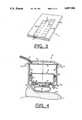
- FIG. 1is a view of the transducer housing of the present invention attached to a patient's wrist.
- FIG. 2ais an illustration of the force balance conditions for a sensing element positioned over a superficial unflattened artery.
- FIG. 2bis an illustration of the force balance conditions for a sensing element positioned over a superficial artery which has been partially flattened.
- FIG. 3is an isometric view of a sensor array of the type employed in the present invention.
- FIG. 4is cross-sectional side view of the transducer housing of the present invention attached to a patient's wrist with the underlying radial artery properly depressed.
- FIG. 5is a detailed cross-sectional side view of the sensor mounting platform of the preferred embodiment.
- FIG. 6is a section view, the section cut being taken along line 6--6 of FIG. 5, showing the sensor attached to the mounting platform on the lower face of the sensor piston.
- the transducer housing of the present inventionis shown attached to a patient's wrist.
- the housing 10has the general appearance of an ordinary wristwatch and is secured to the patient's wrist by an adjustable band 12.
- a cable assembly 14 connected to the housing 10contains electrical cables for carrying electrical signals to and from the transducer.
- the cable assembly 14also contains a pneumatic tube for providing pressurized air to the interior of the housing in order to bring the sensor into contact with the patient's skin in a manner described in greater detail hereinbelow.
- the underlying arterybe partially compressed. Specifically, it is important that the artery be flattened by a plane surface so that the stresses developed in the arterial wall perpendicular to the face of the sensor are negligible. This generally requires that the blood pressure measurement be taken on a superficial artery which runs over bone, against which the artery can be flattened.
- FIGS. 2a and 2billustrate stresses in the wall of a superficial artery such as the radial artery of the wrist.
- FIG. 2athe force balance on a small segment of arterial wall is illustrated for an unflattened artery.
- a sensor 16is shown exerting a compressional force against an artery 18.
- the artery 18overlies a bone 20, which is illustrated with a ground symbol.
- F Rrepresents the reaction force which is measured by the sensor
- F Wis the force due to stresses in the artery wall
- F BPis the force developed by blood pressure in the artery.
- the arterybehaves much like an ideal membrane, supporting only tensile stresses tangent to its surface.
- the angle, ⁇ , of the F W vectoris as shown in FIG.
- ⁇is nonzero for an unflattened artery.
- This wall stressreduces the amount of stress transmitted through the tissue to the surface of the tonometer sensor.
- the pressure (normal stress) measured by the sensor at the skin surfaceis lower than the actual blood pressure. This condition can be seen by summing the Y-direction force components shown in FIG. 2a:
- the force measured by the sensoris lowered by the subtractive effect of the vertical components of the wall forces.
- the sensormeasure pressure only over that portion of the artery wall which is flattened.
- the underlying arteryis flattened over a wider region than the size of a single sensor element. Therefore, the sensor element which happens to be placed over this narrow region where accurate blood pressure readings can be taken must be selected by parts of the tonometer control system not discussed here.
- This preferred measurement regionis illustrated generally by reference number 22 in FIG. 2b.
- the width of the sensor elementmust be less than about one fourth of the diameter of the artery. Furthermore, the sensor element must be placed over the center of the artery. Locating and maintaining a single sensor in this location is, in practice, a very difficult process.
- the array of individual sensing elements 24may be formed in a thin rectangular monocrystalline silicon chip 26 by using modern but conventional integrated circuit fabrication techniques. Typical dimensions for such a sensor are 5 mm by 7 mm with a thickness of approximately 0.2 mm. Each of the individual sensors 24 in the illustration occupies a square area of approximately 0.50 mm ⁇ 0.50 mm. The silicon thickness in these areas is reduced by anistropic etching to a thickness of approximately 10 microns.
- One method which can be used to form such a silicon chip with regions of predetermined thickness in the chipis described in U.S. Pat. No. 3,888,708 issued to Wise, et al. for "Method for Forming Regions of Predetermined Thickness in Silicon.”
- the array of transducer elements 24 in this caseis made up of two side by side sets 24a and 24b, with each of the sets being arranged in a straight line parallel to the other set and each individual transducer element 24 of one set being offset lengthwise (along the respective longitudinal axis) so that the individual transducer elements of one set (e.g., 24a) are centered in the space between the individual transducers of the other set (e.g., 24b).
- the central longitudinal axis of each of the parallel sets 24a and 24bis intended to be positioned essentially perpendicular to the artery 18 where pressure is monitored.
- This sensor spacing configurationhelps to minimize the center-to-center spacing of the individual sensor elements in the direction perpendicular to the axis of the artery. Because the individual sensor elements are so small, a number of them will overlie the artery 18. In order that the chip present a flat surface to the skin, the etched area under each individual transducer element is filled with silicone rubber 27 or some other low-modulus incompressible material.
- the transducer case 10is a generally cylindrical, hollow container having a rigid back and side walls 30 and 32, respectively.
- the sensor chip 16is mounted on a platform 34 which is attached to a support frame 35 which is further attached to the lower rim of the sidewall 43 of a cup-shaped transducer piston 38. Because of the overall shape of the platform assembly, it is sometimes referred to as a "stadium" assembly.
- the transducer piston 38is attached to the inside of the transducer case by means of a cup-like silicone rubber bellows 36.
- the bellowsis attached to the transducer piston 38 by an annular ring 39 and is sealed to an annular ring 37 which is attached to the transducer case 10. Since the flexible rubber bellows 36 is sealed both to the transducer piston 38 and to the inside of the transducer case 10, pressurized air introduced into the interior of the case causes the operative face to be pneumatically loaded (air supply to rubber bellows not specifically illustrated), thereby keeping constant the force applied to the piston assembly.
- the pneumatic pressure applied inside the rubber bellows 36may be adjusted to supply the compressional force required to provide the necessary flattening of the artery wall, thus allowing the device to meet the flattening criteria described above in connection with FIG. 2b.
- the operative face of the piston assemblyincludes the sensor chip 16, along with its included individual transducer elements, the lower surface of the platform 34 and support frame 35, and the curved lower rim of the transducer piston sidewall 44.
- the transducer caseWhen the transducer case is held in place on the wrist, generally over the radial artery, as shown in FIG. 1, and the transducer piston 38 is thus supported over the radial artery by the rubber bellows, air pressure inside the bellows holds the operative face including the sensor array 16 and its supporting structure, against the skin surface with sufficient force to achieve the desired degree of flattening of the wall of the artery. Therefore, the individual sensing elements 24 in the array each will produce an output which is directly responsive to pressure and variations in pressure on the individual element.
- the operative face of the transducer piston 38overlies the radius bone 20 and the flexor tendon 21.
- the sensor 16was mounted flush in the operative face and, therefore, significant pressure was required to compress the underlying artery. This was because the operative face could not compress the artery without also displacing the tendon and exerting considerable pressure on the tissues overlying the prominence of the radius 28 shown in FIG. 4. The pressure exerted on these tissues and the flexor tendon could cause considerable discomfort for the patient.
- the central portion of the lower face of the sensor mounting platform 34is in the form of an inverted truncated pyramid 40, with the sensor chip 16 mounted on the lower face thereof.
- the lower rim of the pyramid 40has a width of approximately 5 mm and a length of approximately 7 mm.
- the curved lower rim of the transducer piston sidewall 44is typically flush with the top of the truncated pyramid 40, but may extend above this level.
- the lower circumferential rim of the piston sidewall 44 as well as layer 42 of the leadframerests on the radius bone and the flexor tendon, as was the case in prior designs.
- the arterycan be flattened without the previously required magnitude of hold down pressure.
- the sensor chipis offset from the rest of the operative face by approximately 2 mm. This dimension is shown by reference number 29 in FIG. 5.
- the pyramid 40is attached to a lead frame assembly comprising a plurality of alternating layers of metal and ceramic material.
- the layers 42, 48 and 50 of the lead frameare formed from a sealing alloy, such as gold plated kovar, and layers 44 and 46 are formed of a ceramic insulating material.
- the layer 48includes a plurality of pads for receiving wires (not shown) which transmit the signals produced by the sensor elements 24 of the sensor array 16.
- the lower face of the sensor assemblyis covered with a layer of silicone rubber having a thickness of approximately 0.003 inches.
- This layerserves both as an electrical insulator and presents a soft, nonabrasive surface to the patient's skin.
- This silicone rubberis also used to fill the etched areas beneath each transducer element. This filling is denoted by reference numeral 27 in FIG. 5.
- FIG. 6is a section view, the section cut being taken along lines 6--6 of FIG. 5, showing the sensor 16 mounted on the mounting platform defined by the inverted truncated pyramid 40.
- the sensor chip 16has a length of approximately 7 mm and a width of approximately 5 mm.
- Anatomical measurementshave shown that the gap between the prominence of the radius bone 28 and the flexor tendon 21 lies in the range of approximately 6 mm to 12 mm for human adults. Shorter females lie near the lower end of this range and taller males near the upper end. For this reason, the length of the chip 16 in the preferred embodiment was chosen to be 7 mm, which is a compromise that gives satisfactory performance with the majority of human adults.
- a chip length between approximately 5 mm and 15 mmcan be used for adult humans without departing from the principles of this invention. Furthermore, the size of the above-mentioned gap is considerably less in children and infants. For example, a chip length between approximately 2 mm and 6 mm would be preferred in a device intended primarily for blood pressure measurements of children. Finally, those familiar with primate anatomy would be able to choose a chip length appropriate for use on chimpanzees, orangutans, baboons, gorillas, etc.
- the hold down pressure required in prior art transducersis often greater than 200 mm of mercury.
- the present inventionit is often possible to obtain adequate flattening of the artery with a hold down pressure of approximately 50 mm of mercury.
- the present inventiontherefore, provides a means for obtaining accurate measurement of blood pressure while minimizing the discomfort to the patient.
Landscapes
- Health & Medical Sciences (AREA)
- Life Sciences & Earth Sciences (AREA)
- Cardiology (AREA)
- Vascular Medicine (AREA)
- Engineering & Computer Science (AREA)
- Medical Informatics (AREA)
- Physics & Mathematics (AREA)
- Ophthalmology & Optometry (AREA)
- Biophysics (AREA)
- Pathology (AREA)
- Dentistry (AREA)
- Biomedical Technology (AREA)
- Heart & Thoracic Surgery (AREA)
- Physiology (AREA)
- Molecular Biology (AREA)
- Surgery (AREA)
- Animal Behavior & Ethology (AREA)
- General Health & Medical Sciences (AREA)
- Public Health (AREA)
- Veterinary Medicine (AREA)
- Measuring Pulse, Heart Rate, Blood Pressure Or Blood Flow (AREA)
Abstract
Description
Sum(F.sub.Y)=0→F.sub.R =F.sub.BP -2F.sub.W sinφ
Claims (9)
Priority Applications (1)
| Application Number | Priority Date | Filing Date | Title |
|---|---|---|---|
| US07/349,937US4987900A (en) | 1987-04-21 | 1989-05-03 | Apparatus for positioning transducer for blood pressure monitor |
Applications Claiming Priority (2)
| Application Number | Priority Date | Filing Date | Title |
|---|---|---|---|
| US4124587A | 1987-04-21 | 1987-04-21 | |
| US07/349,937US4987900A (en) | 1987-04-21 | 1989-05-03 | Apparatus for positioning transducer for blood pressure monitor |
Related Parent Applications (1)
| Application Number | Title | Priority Date | Filing Date |
|---|---|---|---|
| US4124587AContinuation | 1987-04-21 | 1987-04-21 |
Publications (1)
| Publication Number | Publication Date |
|---|---|
| US4987900Atrue US4987900A (en) | 1991-01-29 |
Family
ID=26717943
Family Applications (1)
| Application Number | Title | Priority Date | Filing Date |
|---|---|---|---|
| US07/349,937Expired - LifetimeUS4987900A (en) | 1987-04-21 | 1989-05-03 | Apparatus for positioning transducer for blood pressure monitor |
Country Status (1)
| Country | Link |
|---|---|
| US (1) | US4987900A (en) |
Cited By (62)
| Publication number | Priority date | Publication date | Assignee | Title |
|---|---|---|---|---|
| US5101829A (en)* | 1990-01-09 | 1992-04-07 | Colin Electronics Co., Ltd. | Semiconductor pressure pulse wave sensor |
| US5139026A (en)* | 1988-12-12 | 1992-08-18 | Colin Electronics Co., Ltd. | Pulse wave detecting apparatus and pulse wave detecting method |
| US5176143A (en)* | 1991-06-17 | 1993-01-05 | Colin Electronics Company, Ltd. | Tonometer transducer positioning system |
| DE4220532A1 (en)* | 1991-06-28 | 1993-01-14 | Colin Electronics | BLOOD PRESSURE MONITORING SYSTEM |
| US5179956A (en)* | 1990-07-06 | 1993-01-19 | Colin Electronics Co., Ltd. | Contact pressure sensor |
| US5183050A (en)* | 1991-04-16 | 1993-02-02 | Colin Electronics Co., Ltd. | Pulse wave sensor |
| DE4224060A1 (en)* | 1991-07-29 | 1993-02-04 | Colin Electronics | PULSE PRESSURE SHAFT TRANSFER SHEET FOR A PULSE PRESSURE SENSOR |
| US5238000A (en)* | 1990-09-10 | 1993-08-24 | Colin Electronics Co., Ltd. | Pulse wave detecting apparatus |
| US5261412A (en)* | 1992-11-20 | 1993-11-16 | Ivac Corporation | Method of continuously monitoring blood pressure |
| US5289823A (en)* | 1992-05-12 | 1994-03-01 | Colin Electronics Co., Ltd. | Non-invasive aortic blood flow sensor and method for non-invasively measuring aortic blood flow |
| US5307811A (en)* | 1990-06-11 | 1994-05-03 | Radi Medical Systems Ab | Femoral compression device |
| US5368039A (en)* | 1993-07-26 | 1994-11-29 | Moses; John A. | Method and apparatus for determining blood pressure |
| EP0587686A4 (en)* | 1991-05-14 | 1994-12-07 | Ivac Corp | Apparatus for applanating an artery. |
| US5617868A (en)* | 1994-11-22 | 1997-04-08 | Colin Corporation | Pulse wave detecting apparatus |
| EP0639062A4 (en)* | 1992-04-15 | 1998-09-30 | Ivac Corp | Method of determining optimum arterial applanation. |
| US5908027A (en)* | 1994-08-22 | 1999-06-01 | Alaris Medical Systems, Inc. | Tonometry system for monitoring blood pressure |
| WO2000017615A3 (en)* | 1998-09-23 | 2000-07-13 | Keith Bridger | Physiological sensing device |
| WO2000062666A1 (en)* | 1999-04-21 | 2000-10-26 | Jie Kan | A noninvasive blood pressure measuring method and apparatus |
| US6171255B1 (en)* | 1999-01-20 | 2001-01-09 | Dr{umlaut over (a)}ger Medizintechnik GmbH | Device for noninvasive blood pressure measurement |
| US20010056240A1 (en)* | 2000-06-14 | 2001-12-27 | U.S. Philips Corporation. | Device for monitoring a vital sign |
| US20040243009A1 (en)* | 2003-05-30 | 2004-12-02 | Casio Computer Co., Ltd. | Wrist-worn high-accuracy pulsation measuring apparatus |
| US20050124897A1 (en)* | 2003-12-03 | 2005-06-09 | Scimed Life Systems, Inc. | Apparatus and methods for delivering acoustic energy to body tissue |
| US20050177047A1 (en)* | 2002-04-02 | 2005-08-11 | Harpas Peter C. | Device for, and a method of, transcutaneous pressure waveform sensing of an artery and a related target apparatus |
| US20060036185A1 (en)* | 2004-08-14 | 2006-02-16 | Lewicke John A | Patient monitoring system with blood pressure measurement capacity |
| US20060036137A1 (en)* | 2004-08-13 | 2006-02-16 | John Lewicke | Patient monitoring apparatus |
| US20060199659A1 (en)* | 2005-03-03 | 2006-09-07 | Caldwell Theodore W | ShotwatchTM |
| US20060241425A1 (en)* | 2004-03-29 | 2006-10-26 | Qinetiq Limited | Ultrasound detection |
| US20080021325A1 (en)* | 2006-06-12 | 2008-01-24 | Drost Cornelis J | System and method of perivascular pressure and flow measurement |
| US20080274819A1 (en)* | 2007-05-04 | 2008-11-06 | Caldwell Theodore W | Grip Pressure Sensor |
| US20090076398A1 (en)* | 2003-07-07 | 2009-03-19 | Nellcor Puritan Bennett Ireland | Continuous Non-Invasive Blood Pressure Measurement Apparatus and Methods Providing Automatic Recalibration |
| US20090326353A1 (en)* | 2008-06-30 | 2009-12-31 | Nellcor Puritan Bennett Ireland | Processing and detecting baseline changes in signals |
| US20090326386A1 (en)* | 2008-06-30 | 2009-12-31 | Nellcor Puritan Bennett Ireland | Systems and Methods for Non-Invasive Blood Pressure Monitoring |
| US20090326393A1 (en)* | 2008-06-30 | 2009-12-31 | Nellcor Puritan Bennett Ireland | Systems and Methods for Non-Invasive Continuous Blood Pressure Determination |
| US20100081892A1 (en)* | 2008-09-30 | 2010-04-01 | NelIcor Puritan Bennett Ireland | Systems and Methods for Combined Pulse Oximetry and Blood Pressure Measurement |
| US20100081943A1 (en)* | 2008-09-30 | 2010-04-01 | Nellcor Puritan Bennett Ireland | Detecting Sleep Events Using Localized Blood Pressure Changes |
| US20100081940A1 (en)* | 2008-09-30 | 2010-04-01 | Nellcor Puritan Bennett Llc | Laser Self-Mixing Sensors for Biological Sensing |
| US20100081945A1 (en)* | 2008-09-30 | 2010-04-01 | Nellcor Puritan Bennett Ireland | Systems and Methods for Maintaining Blood Pressure Monitor Calibration |
| US20100081944A1 (en)* | 2008-09-30 | 2010-04-01 | Nellcor Puritan Bennett Ireland | Systems and Methods for Recalibrating a Non-Invasive Blood Pressure Monitor |
| US20100324431A1 (en)* | 2009-06-18 | 2010-12-23 | Nellcor Puritan Bennett Ireland | Determining Disease State Using An Induced Load |
| US20100332173A1 (en)* | 2009-06-30 | 2010-12-30 | Nellcor Puritan Bennett Ireland | Systems and methods for assessing measurements in physiological monitoring devices |
| US20100331724A1 (en)* | 2009-06-30 | 2010-12-30 | Nellcor Puritan Bennett Ireland | Determining a characteristic blood pressure |
| US20110021929A1 (en)* | 2009-07-27 | 2011-01-27 | Nellcor Puritan Bennett Ireland | Systems and methods for continuous non-invasive blood pressure monitoring |
| US20110028854A1 (en)* | 2009-07-31 | 2011-02-03 | Nellcor Puritain Bennett Ireland | Systems and methods for non-invasive determination of blood pressure |
| US20110071406A1 (en)* | 2009-09-21 | 2011-03-24 | Nellcor Puritan Bennett Ireland | Determining A Characteristic Respiration Rate |
| US20110077531A1 (en)* | 2009-09-29 | 2011-03-31 | Nellcor Puritan Bennett Ireland | Systems and methods for high-pass filtering a photoplethysmograph signal |
| US8216136B2 (en) | 2009-03-05 | 2012-07-10 | Nellcor Puritan Bennett Llc | Systems and methods for monitoring heart rate and blood pressure correlation |
| US8463347B2 (en) | 2009-09-30 | 2013-06-11 | Nellcor Puritan Bennett Ireland | Systems and methods for normalizing a plethysmograph signal for improved feature analysis |
| US8506498B2 (en) | 2008-07-15 | 2013-08-13 | Nellcor Puritan Bennett Ireland | Systems and methods using induced perturbation to determine physiological parameters |
| US8825428B2 (en) | 2010-11-30 | 2014-09-02 | Neilcor Puritan Bennett Ireland | Methods and systems for recalibrating a blood pressure monitor with memory |
| US8898037B2 (en) | 2010-04-28 | 2014-11-25 | Nellcor Puritan Bennett Ireland | Systems and methods for signal monitoring using Lissajous figures |
| US9060695B2 (en) | 2011-11-30 | 2015-06-23 | Covidien Lp | Systems and methods for determining differential pulse transit time from the phase difference of two analog plethysmographs |
| US20150265218A1 (en)* | 2002-08-01 | 2015-09-24 | Tensys Medical, Inc. | Method and apparatus for control of non-invasive parameter measurements |
| US9204809B2 (en) | 2012-02-01 | 2015-12-08 | Hong Kong Applied Science and Technology Research Institute Company Limited | Blood pressure measuring device and method of calibrating thereof |
| US9259160B2 (en) | 2010-12-01 | 2016-02-16 | Nellcor Puritan Bennett Ireland | Systems and methods for determining when to measure a physiological parameter |
| US9357934B2 (en) | 2010-12-01 | 2016-06-07 | Nellcor Puritan Bennett Ireland | Systems and methods for physiological event marking |
| US9451887B2 (en) | 2010-03-31 | 2016-09-27 | Nellcor Puritan Bennett Ireland | Systems and methods for measuring electromechanical delay of the heart |
| US20170347957A1 (en)* | 2014-12-18 | 2017-12-07 | Koninklijke Philips N.V. | Measuring of a physiological parameter using a wearable sensor |
| US10349847B2 (en) | 2015-01-15 | 2019-07-16 | Samsung Electronics Co., Ltd. | Apparatus for detecting bio-information |
| US10357165B2 (en) | 2015-09-01 | 2019-07-23 | Samsung Electronics Co., Ltd. | Method and apparatus for acquiring bioinformation and apparatus for testing bioinformation |
| US10405806B2 (en) | 2015-03-06 | 2019-09-10 | Samsung Electronics Co., Ltd. | Apparatus for and method of measuring blood pressure |
| US10568527B2 (en) | 2014-09-03 | 2020-02-25 | Samsung Electronics Co., Ltd. | Apparatus for and method of monitoring blood pressure and wearable device having function of monitoring blood pressure |
| US10820858B2 (en) | 2016-10-12 | 2020-11-03 | Samsung Electronics Co., Ltd. | Apparatus and method for estimating biometric information |
Citations (13)
| Publication number | Priority date | Publication date | Assignee | Title |
|---|---|---|---|---|
| US3102534A (en)* | 1962-06-21 | 1963-09-03 | Du Pont | Physiologic fluid pressure measuring apparatus |
| US3154067A (en)* | 1961-10-11 | 1964-10-27 | Robert L Gannon | Body function sensor |
| US3903873A (en)* | 1974-05-13 | 1975-09-09 | Douglas E Royal | Pulse contour measuring instrument |
| US3926179A (en)* | 1974-04-03 | 1975-12-16 | Wisconsin Alumni Res Found | Blood pressure measuring apparatus |
| US4030484A (en)* | 1974-11-14 | 1977-06-21 | Stoelting Company | Non-invasive blood pressure monitor |
| US4068654A (en)* | 1975-02-19 | 1978-01-17 | Oiva A. Paavola | Blood pressure measuring apparatus and method |
| US4185621A (en)* | 1977-10-28 | 1980-01-29 | Triad, Inc. | Body parameter display incorporating a battery charger |
| US4307727A (en)* | 1979-10-15 | 1981-12-29 | Tech Engineering And Design, Inc. | Wrist band transducer support and tensioning apparatus |
| US4423738A (en)* | 1977-11-04 | 1984-01-03 | Sri International | Noninvasive blood pressure monitoring transducer |
| US4489731A (en)* | 1983-02-04 | 1984-12-25 | H & B Technologies, Inc. | Pulse rate monitor |
| US4561447A (en)* | 1983-01-14 | 1985-12-31 | Nippon, Colin Co., Ltd. | Apparatus and method of detecting arterial pulse wave |
| GB2180944A (en)* | 1985-09-26 | 1987-04-08 | M D Edward Harry Hon | Continuous cutaneous blood pressure measurement |
| US4867170A (en)* | 1987-07-03 | 1989-09-19 | Kabuskiki Kaisha Hi Bridge | Measuring apparatus for blood pressure |
- 1989
- 1989-05-03USUS07/349,937patent/US4987900A/ennot_activeExpired - Lifetime
Patent Citations (13)
| Publication number | Priority date | Publication date | Assignee | Title |
|---|---|---|---|---|
| US3154067A (en)* | 1961-10-11 | 1964-10-27 | Robert L Gannon | Body function sensor |
| US3102534A (en)* | 1962-06-21 | 1963-09-03 | Du Pont | Physiologic fluid pressure measuring apparatus |
| US3926179A (en)* | 1974-04-03 | 1975-12-16 | Wisconsin Alumni Res Found | Blood pressure measuring apparatus |
| US3903873A (en)* | 1974-05-13 | 1975-09-09 | Douglas E Royal | Pulse contour measuring instrument |
| US4030484A (en)* | 1974-11-14 | 1977-06-21 | Stoelting Company | Non-invasive blood pressure monitor |
| US4068654A (en)* | 1975-02-19 | 1978-01-17 | Oiva A. Paavola | Blood pressure measuring apparatus and method |
| US4185621A (en)* | 1977-10-28 | 1980-01-29 | Triad, Inc. | Body parameter display incorporating a battery charger |
| US4423738A (en)* | 1977-11-04 | 1984-01-03 | Sri International | Noninvasive blood pressure monitoring transducer |
| US4307727A (en)* | 1979-10-15 | 1981-12-29 | Tech Engineering And Design, Inc. | Wrist band transducer support and tensioning apparatus |
| US4561447A (en)* | 1983-01-14 | 1985-12-31 | Nippon, Colin Co., Ltd. | Apparatus and method of detecting arterial pulse wave |
| US4489731A (en)* | 1983-02-04 | 1984-12-25 | H & B Technologies, Inc. | Pulse rate monitor |
| GB2180944A (en)* | 1985-09-26 | 1987-04-08 | M D Edward Harry Hon | Continuous cutaneous blood pressure measurement |
| US4867170A (en)* | 1987-07-03 | 1989-09-19 | Kabuskiki Kaisha Hi Bridge | Measuring apparatus for blood pressure |
Cited By (94)
| Publication number | Priority date | Publication date | Assignee | Title |
|---|---|---|---|---|
| US5139026A (en)* | 1988-12-12 | 1992-08-18 | Colin Electronics Co., Ltd. | Pulse wave detecting apparatus and pulse wave detecting method |
| US5101829A (en)* | 1990-01-09 | 1992-04-07 | Colin Electronics Co., Ltd. | Semiconductor pressure pulse wave sensor |
| US5307811A (en)* | 1990-06-11 | 1994-05-03 | Radi Medical Systems Ab | Femoral compression device |
| US5179956A (en)* | 1990-07-06 | 1993-01-19 | Colin Electronics Co., Ltd. | Contact pressure sensor |
| US5238000A (en)* | 1990-09-10 | 1993-08-24 | Colin Electronics Co., Ltd. | Pulse wave detecting apparatus |
| US5183050A (en)* | 1991-04-16 | 1993-02-02 | Colin Electronics Co., Ltd. | Pulse wave sensor |
| EP0587686A4 (en)* | 1991-05-14 | 1994-12-07 | Ivac Corp | Apparatus for applanating an artery. |
| US5176143A (en)* | 1991-06-17 | 1993-01-05 | Colin Electronics Company, Ltd. | Tonometer transducer positioning system |
| DE4220532A1 (en)* | 1991-06-28 | 1993-01-14 | Colin Electronics | BLOOD PRESSURE MONITORING SYSTEM |
| DE4224060A1 (en)* | 1991-07-29 | 1993-02-04 | Colin Electronics | PULSE PRESSURE SHAFT TRANSFER SHEET FOR A PULSE PRESSURE SENSOR |
| EP0639062A4 (en)* | 1992-04-15 | 1998-09-30 | Ivac Corp | Method of determining optimum arterial applanation. |
| US5289823A (en)* | 1992-05-12 | 1994-03-01 | Colin Electronics Co., Ltd. | Non-invasive aortic blood flow sensor and method for non-invasively measuring aortic blood flow |
| US5261412A (en)* | 1992-11-20 | 1993-11-16 | Ivac Corporation | Method of continuously monitoring blood pressure |
| US5368039A (en)* | 1993-07-26 | 1994-11-29 | Moses; John A. | Method and apparatus for determining blood pressure |
| US5551438A (en)* | 1993-07-26 | 1996-09-03 | Moses; John A. | Method and apparatus for determining blood pressure |
| US6290650B1 (en) | 1994-08-22 | 2001-09-18 | Alaris Medical Systems, Inc. | Tonometry system for monitoring blood pressure |
| US5908027A (en)* | 1994-08-22 | 1999-06-01 | Alaris Medical Systems, Inc. | Tonometry system for monitoring blood pressure |
| US5617868A (en)* | 1994-11-22 | 1997-04-08 | Colin Corporation | Pulse wave detecting apparatus |
| US6491647B1 (en)* | 1998-09-23 | 2002-12-10 | Active Signal Technologies, Inc. | Physiological sensing device |
| WO2000017615A3 (en)* | 1998-09-23 | 2000-07-13 | Keith Bridger | Physiological sensing device |
| US6171255B1 (en)* | 1999-01-20 | 2001-01-09 | Dr{umlaut over (a)}ger Medizintechnik GmbH | Device for noninvasive blood pressure measurement |
| WO2000062666A1 (en)* | 1999-04-21 | 2000-10-26 | Jie Kan | A noninvasive blood pressure measuring method and apparatus |
| US6932772B2 (en) | 1999-04-21 | 2005-08-23 | Jie Kan | Noninvasive blood pressure measuring method and apparatus |
| US20010056240A1 (en)* | 2000-06-14 | 2001-12-27 | U.S. Philips Corporation. | Device for monitoring a vital sign |
| US6811535B2 (en)* | 2000-06-14 | 2004-11-02 | Koninklijke Philips Electronics N.V. | Device for monitoring a vital sign |
| US20050010119A1 (en)* | 2000-06-14 | 2005-01-13 | Yoram Palti | Device for monitoring a vital sign |
| US20050177047A1 (en)* | 2002-04-02 | 2005-08-11 | Harpas Peter C. | Device for, and a method of, transcutaneous pressure waveform sensing of an artery and a related target apparatus |
| US20150265218A1 (en)* | 2002-08-01 | 2015-09-24 | Tensys Medical, Inc. | Method and apparatus for control of non-invasive parameter measurements |
| US20040243009A1 (en)* | 2003-05-30 | 2004-12-02 | Casio Computer Co., Ltd. | Wrist-worn high-accuracy pulsation measuring apparatus |
| US7341561B2 (en)* | 2003-05-30 | 2008-03-11 | Casio Computer Co., Ltd. | Wrist-worn high-accuracy pulsation measuring apparatus |
| US8560245B2 (en) | 2003-07-07 | 2013-10-15 | Nellcor Puritan Bennett Ireland | Continuous non-invasive blood pressure measurement apparatus and methods providing automatic recalibration |
| US9949648B2 (en) | 2003-07-07 | 2018-04-24 | Nellcor Puritan Bennett Ireland | Continuous non-invasive blood pressure measurement apparatus and methods providing automatic recalibration |
| US20090076398A1 (en)* | 2003-07-07 | 2009-03-19 | Nellcor Puritan Bennett Ireland | Continuous Non-Invasive Blood Pressure Measurement Apparatus and Methods Providing Automatic Recalibration |
| US20050124897A1 (en)* | 2003-12-03 | 2005-06-09 | Scimed Life Systems, Inc. | Apparatus and methods for delivering acoustic energy to body tissue |
| US20100049101A1 (en)* | 2003-12-03 | 2010-02-25 | Boston Scientific Scimed Inc. | Apparatus and Methods for Delivering Acoustic Energy to Body Tissue |
| US20060241425A1 (en)* | 2004-03-29 | 2006-10-26 | Qinetiq Limited | Ultrasound detection |
| US20060036137A1 (en)* | 2004-08-13 | 2006-02-16 | John Lewicke | Patient monitoring apparatus |
| US7438687B2 (en) | 2004-08-14 | 2008-10-21 | Nova Technology Corporation | Patient monitoring system with blood pressure measurement capacity |
| US20060036185A1 (en)* | 2004-08-14 | 2006-02-16 | Lewicke John A | Patient monitoring system with blood pressure measurement capacity |
| US8123624B2 (en) | 2005-03-03 | 2012-02-28 | Theodore Weissenburger Caldwell | Shot Monitoring Watch |
| US20060199659A1 (en)* | 2005-03-03 | 2006-09-07 | Caldwell Theodore W | ShotwatchTM |
| US8968204B2 (en) | 2006-06-12 | 2015-03-03 | Transonic Systems, Inc. | System and method of perivascular pressure and flow measurement |
| US20080021325A1 (en)* | 2006-06-12 | 2008-01-24 | Drost Cornelis J | System and method of perivascular pressure and flow measurement |
| US8033916B2 (en)* | 2007-05-04 | 2011-10-11 | Theodore Caldwell | Grip pressure sensor |
| US20080274819A1 (en)* | 2007-05-04 | 2008-11-06 | Caldwell Theodore W | Grip Pressure Sensor |
| US20090326393A1 (en)* | 2008-06-30 | 2009-12-31 | Nellcor Puritan Bennett Ireland | Systems and Methods for Non-Invasive Continuous Blood Pressure Determination |
| US9378332B2 (en) | 2008-06-30 | 2016-06-28 | Nellcor Puritan Bennett Ireland | Processing and detecting baseline changes in signals |
| US20090326386A1 (en)* | 2008-06-30 | 2009-12-31 | Nellcor Puritan Bennett Ireland | Systems and Methods for Non-Invasive Blood Pressure Monitoring |
| US20090326353A1 (en)* | 2008-06-30 | 2009-12-31 | Nellcor Puritan Bennett Ireland | Processing and detecting baseline changes in signals |
| US8660799B2 (en) | 2008-06-30 | 2014-02-25 | Nellcor Puritan Bennett Ireland | Processing and detecting baseline changes in signals |
| US8398556B2 (en) | 2008-06-30 | 2013-03-19 | Covidien Lp | Systems and methods for non-invasive continuous blood pressure determination |
| US8506498B2 (en) | 2008-07-15 | 2013-08-13 | Nellcor Puritan Bennett Ireland | Systems and methods using induced perturbation to determine physiological parameters |
| US20100081944A1 (en)* | 2008-09-30 | 2010-04-01 | Nellcor Puritan Bennett Ireland | Systems and Methods for Recalibrating a Non-Invasive Blood Pressure Monitor |
| US9301697B2 (en) | 2008-09-30 | 2016-04-05 | Nellcor Puritan Bennett Ireland | Systems and methods for recalibrating a non-invasive blood pressure monitor |
| US20100081892A1 (en)* | 2008-09-30 | 2010-04-01 | NelIcor Puritan Bennett Ireland | Systems and Methods for Combined Pulse Oximetry and Blood Pressure Measurement |
| US9687161B2 (en) | 2008-09-30 | 2017-06-27 | Nellcor Puritan Bennett Ireland | Systems and methods for maintaining blood pressure monitor calibration |
| US20100081945A1 (en)* | 2008-09-30 | 2010-04-01 | Nellcor Puritan Bennett Ireland | Systems and Methods for Maintaining Blood Pressure Monitor Calibration |
| US20100081940A1 (en)* | 2008-09-30 | 2010-04-01 | Nellcor Puritan Bennett Llc | Laser Self-Mixing Sensors for Biological Sensing |
| US9314168B2 (en) | 2008-09-30 | 2016-04-19 | Nellcor Puritan Bennett Ireland | Detecting sleep events using localized blood pressure changes |
| US20100081943A1 (en)* | 2008-09-30 | 2010-04-01 | Nellcor Puritan Bennett Ireland | Detecting Sleep Events Using Localized Blood Pressure Changes |
| US8532751B2 (en) | 2008-09-30 | 2013-09-10 | Covidien Lp | Laser self-mixing sensors for biological sensing |
| US8932219B2 (en) | 2009-03-05 | 2015-01-13 | Nellcor Puritan Bennett Ireland | Systems and methods for monitoring heart rate and blood pressure correlation |
| US8216136B2 (en) | 2009-03-05 | 2012-07-10 | Nellcor Puritan Bennett Llc | Systems and methods for monitoring heart rate and blood pressure correlation |
| US20100324431A1 (en)* | 2009-06-18 | 2010-12-23 | Nellcor Puritan Bennett Ireland | Determining Disease State Using An Induced Load |
| US20100331724A1 (en)* | 2009-06-30 | 2010-12-30 | Nellcor Puritan Bennett Ireland | Determining a characteristic blood pressure |
| US20100332173A1 (en)* | 2009-06-30 | 2010-12-30 | Nellcor Puritan Bennett Ireland | Systems and methods for assessing measurements in physiological monitoring devices |
| US8290730B2 (en) | 2009-06-30 | 2012-10-16 | Nellcor Puritan Bennett Ireland | Systems and methods for assessing measurements in physiological monitoring devices |
| US9198582B2 (en) | 2009-06-30 | 2015-12-01 | Nellcor Puritan Bennett Ireland | Determining a characteristic physiological parameter |
| US20110021929A1 (en)* | 2009-07-27 | 2011-01-27 | Nellcor Puritan Bennett Ireland | Systems and methods for continuous non-invasive blood pressure monitoring |
| US8628477B2 (en) | 2009-07-31 | 2014-01-14 | Nellcor Puritan Bennett Ireland | Systems and methods for non-invasive determination of blood pressure |
| US20110028854A1 (en)* | 2009-07-31 | 2011-02-03 | Nellcor Puritain Bennett Ireland | Systems and methods for non-invasive determination of blood pressure |
| US20110071406A1 (en)* | 2009-09-21 | 2011-03-24 | Nellcor Puritan Bennett Ireland | Determining A Characteristic Respiration Rate |
| US9220440B2 (en) | 2009-09-21 | 2015-12-29 | Nellcor Puritan Bennett Ireland | Determining a characteristic respiration rate |
| US9649071B2 (en) | 2009-09-29 | 2017-05-16 | Nellcor Puritan Bennett Ireland | Systems and methods for high-pass filtering a photoplethysmograph signal |
| US9066660B2 (en) | 2009-09-29 | 2015-06-30 | Nellcor Puritan Bennett Ireland | Systems and methods for high-pass filtering a photoplethysmograph signal |
| US20110077531A1 (en)* | 2009-09-29 | 2011-03-31 | Nellcor Puritan Bennett Ireland | Systems and methods for high-pass filtering a photoplethysmograph signal |
| US8463347B2 (en) | 2009-09-30 | 2013-06-11 | Nellcor Puritan Bennett Ireland | Systems and methods for normalizing a plethysmograph signal for improved feature analysis |
| US9451887B2 (en) | 2010-03-31 | 2016-09-27 | Nellcor Puritan Bennett Ireland | Systems and methods for measuring electromechanical delay of the heart |
| US8898037B2 (en) | 2010-04-28 | 2014-11-25 | Nellcor Puritan Bennett Ireland | Systems and methods for signal monitoring using Lissajous figures |
| US9289136B2 (en) | 2010-11-30 | 2016-03-22 | Nellcor Puritan Bennett Ireland | Methods and systems for recalibrating a blood pressure monitor with memory |
| US8825428B2 (en) | 2010-11-30 | 2014-09-02 | Neilcor Puritan Bennett Ireland | Methods and systems for recalibrating a blood pressure monitor with memory |
| US10165953B2 (en) | 2010-11-30 | 2019-01-01 | Nellcor Puritan Bennett Ireland | Methods and systems for recalibrating a blood pressure monitor with memory |
| US9259160B2 (en) | 2010-12-01 | 2016-02-16 | Nellcor Puritan Bennett Ireland | Systems and methods for determining when to measure a physiological parameter |
| US9357934B2 (en) | 2010-12-01 | 2016-06-07 | Nellcor Puritan Bennett Ireland | Systems and methods for physiological event marking |
| US9060695B2 (en) | 2011-11-30 | 2015-06-23 | Covidien Lp | Systems and methods for determining differential pulse transit time from the phase difference of two analog plethysmographs |
| US9204809B2 (en) | 2012-02-01 | 2015-12-08 | Hong Kong Applied Science and Technology Research Institute Company Limited | Blood pressure measuring device and method of calibrating thereof |
| US10568527B2 (en) | 2014-09-03 | 2020-02-25 | Samsung Electronics Co., Ltd. | Apparatus for and method of monitoring blood pressure and wearable device having function of monitoring blood pressure |
| US20170347957A1 (en)* | 2014-12-18 | 2017-12-07 | Koninklijke Philips N.V. | Measuring of a physiological parameter using a wearable sensor |
| US10575780B2 (en)* | 2014-12-18 | 2020-03-03 | Koninklijke Philips N.V. | Measuring of a physiological parameter using a wearable sensor |
| US10349847B2 (en) | 2015-01-15 | 2019-07-16 | Samsung Electronics Co., Ltd. | Apparatus for detecting bio-information |
| US10405806B2 (en) | 2015-03-06 | 2019-09-10 | Samsung Electronics Co., Ltd. | Apparatus for and method of measuring blood pressure |
| US10357165B2 (en) | 2015-09-01 | 2019-07-23 | Samsung Electronics Co., Ltd. | Method and apparatus for acquiring bioinformation and apparatus for testing bioinformation |
| US10820858B2 (en) | 2016-10-12 | 2020-11-03 | Samsung Electronics Co., Ltd. | Apparatus and method for estimating biometric information |
| US11666277B2 (en) | 2016-10-12 | 2023-06-06 | Samsung Electronics Co., Ltd. | Apparatus and method for estimating biometric information |
Similar Documents
| Publication | Publication Date | Title |
|---|---|---|
| US4987900A (en) | Apparatus for positioning transducer for blood pressure monitor | |
| US4924871A (en) | Motion artifact detection for continuous blood pressure monitor transducer | |
| US4830017A (en) | Automatic positioning system for continuous blood pressure monitor transducer | |
| EP0290593B1 (en) | Blood pressure monitoring method and apparatus | |
| US4860768A (en) | Transducer support base with a depending annular isolation ring | |
| US5101829A (en) | Semiconductor pressure pulse wave sensor | |
| US5467771A (en) | Pulse wave sensor | |
| Pressman et al. | A transducer for the continuous external measurement of arterial blood pressure | |
| US4423738A (en) | Noninvasive blood pressure monitoring transducer | |
| AU736270B2 (en) | Hand-held non-invasive blood pressure measurement device | |
| JP3711287B2 (en) | Device for determining blood pressure | |
| EP0299992B1 (en) | Blood pressure monitoring method and apparatus | |
| US5938618A (en) | Method of positioning a sensor for determining blood pressure of an artery | |
| AU716914B2 (en) | Wrist mounted blood pressure sensor | |
| US4989615A (en) | Apparatus for non-invasive monitoring of uterine contractions | |
| US5184515A (en) | Single diaphragm transducer with multiple sensing elements | |
| US4966156A (en) | Pressurization system for continuous blood pressure monitor transducer | |
| US3219035A (en) | Blood pressure measuring transducer | |
| US4640295A (en) | Tocodynamometer | |
| CA2347716A1 (en) | Non-invasive blood pressure sensor with motion artifact reduction | |
| WO1996025091A9 (en) | Method and apparatus for calculating blood pressure | |
| US20030187370A1 (en) | Uterine contraction sensing system and method | |
| US11209329B2 (en) | Liquid encapsulation device and method for fabricating the same | |
| JPS6176127A (en) | Blood inhibiting apparatus for measuring blood pressure | |
| AU726420B2 (en) | Method and apparatus for calculating blood pressure |
Legal Events
| Date | Code | Title | Description |
|---|---|---|---|
| AS | Assignment | Owner name:COLIN ELECTRONICS CO., LTD., A CO. OF JAPAN Free format text:ASSIGNMENT OF ASSIGNORS INTEREST.;ASSIGNOR:NIPPON COLIN CO., LTD., A CO. OF JAPAN;REEL/FRAME:005360/0703 Effective date:19900618 | |
| STCF | Information on status: patent grant | Free format text:PATENTED CASE | |
| FEPP | Fee payment procedure | Free format text:PAYOR NUMBER ASSIGNED (ORIGINAL EVENT CODE: ASPN); ENTITY STATUS OF PATENT OWNER: SMALL ENTITY | |
| FPAY | Fee payment | Year of fee payment:4 | |
| FPAY | Fee payment | Year of fee payment:8 | |
| FPAY | Fee payment | Year of fee payment:12 | |
| AS | Assignment | Owner name:COLIN MEDICAL TECHNOLOGY CORPORATION, JAPAN Free format text:ASSIGNMENT OF ASSIGNORS INTEREST;ASSIGNOR:COLIN ELECTRONICS CO., LTD.;REEL/FRAME:014428/0957 Effective date:20040205 | |
| AS | Assignment | Owner name:OMRON HEALTHCARE CO., LTD., JAPAN Free format text:ASSIGNMENT OF ASSIGNORS INTEREST;ASSIGNOR:COLIN MEDICAL TECHNOLOGY CORPORATION;REEL/FRAME:017846/0738 Effective date:20060626 |