US4986529A - Four roll inverter - Google Patents
Four roll inverterDownload PDFInfo
- Publication number
- US4986529A US4986529AUS07/258,944US25894488AUS4986529AUS 4986529 AUS4986529 AUS 4986529AUS 25894488 AUS25894488 AUS 25894488AUS 4986529 AUS4986529 AUS 4986529A
- Authority
- US
- United States
- Prior art keywords
- sheet
- diverter
- nips
- sheets
- Prior art date
- Legal status (The legal status is an assumption and is not a legal conclusion. Google has not performed a legal analysis and makes no representation as to the accuracy of the status listed.)
- Expired - Fee Related
Links
- 230000006835compressionEffects0.000claimsdescription13
- 238000007906compressionMethods0.000claimsdescription13
- 238000011144upstream manufacturingMethods0.000claimsdescription7
- 108091008695photoreceptorsProteins0.000description4
- 239000000463materialSubstances0.000description2
- 229910000831SteelInorganic materials0.000description1
- 230000000694effectsEffects0.000description1
- 238000004519manufacturing processMethods0.000description1
- 239000011236particulate materialSubstances0.000description1
- 239000010959steelSubstances0.000description1
- 230000032258transportEffects0.000description1
- 230000007306turnoverEffects0.000description1
- 230000000007visual effectEffects0.000description1
Images

Classifications
- B—PERFORMING OPERATIONS; TRANSPORTING
- B65—CONVEYING; PACKING; STORING; HANDLING THIN OR FILAMENTARY MATERIAL
- B65H—HANDLING THIN OR FILAMENTARY MATERIAL, e.g. SHEETS, WEBS, CABLES
- B65H15/00—Overturning articles
- B—PERFORMING OPERATIONS; TRANSPORTING
- B65—CONVEYING; PACKING; STORING; HANDLING THIN OR FILAMENTARY MATERIAL
- B65H—HANDLING THIN OR FILAMENTARY MATERIAL, e.g. SHEETS, WEBS, CABLES
- B65H2301/00—Handling processes for sheets or webs
- B65H2301/30—Orientation, displacement, position of the handled material
- B65H2301/33—Modifying, selecting, changing orientation
- B65H2301/333—Inverting
- B65H2301/3332—Tri-rollers type
- Y—GENERAL TAGGING OF NEW TECHNOLOGICAL DEVELOPMENTS; GENERAL TAGGING OF CROSS-SECTIONAL TECHNOLOGIES SPANNING OVER SEVERAL SECTIONS OF THE IPC; TECHNICAL SUBJECTS COVERED BY FORMER USPC CROSS-REFERENCE ART COLLECTIONS [XRACs] AND DIGESTS
- Y10—TECHNICAL SUBJECTS COVERED BY FORMER USPC
- Y10S—TECHNICAL SUBJECTS COVERED BY FORMER USPC CROSS-REFERENCE ART COLLECTIONS [XRACs] AND DIGESTS
- Y10S271/00—Sheet feeding or delivering
- Y10S271/902—Reverse direction of sheet movement
Definitions
- This inventionis directed to an apparatus for changing the orientation of a copy sheet. More particularly, the invention is directed to a four roll inverter that includes a spring loaded inversion channel.
- One known sheet-feederfor effecting this includes three rollers in frictional or geared contact with each other, to provide two spaced-apart nips, one being an input nip to an associated downstream sheet pocket, and the other being an output nip for extracting each sheet from the pocket.
- a tri-roll paper inverterthat includes a constant force spring in the back of an inverter chute is disclosed in Xerox Disclosure Journal Publication, Vol. 8, Number 2March/April, Page 101, 1983, In U.S. Pat. No. 4,673,176,an inverter for a copier machine is shown that includes a tri-roll inverting mechanism.
- a sheet turn over mechanismis disclosed in U.S. Pat. No. 4,699,367 that includes a three-roller cluster and a pair of diverters in the paper travel path.
- the present inventionaims at providing an inverter designed to have both simplex and duplex sheets fed to it along a common input path into a pocket at least partially surrounded by a low-rate linear compression spring, from which the sheets are extracted and fed along one of two different output paths.
- a corrugatorcould be placed along the input path if desired.
- FIG. 1is a diagrammatic view of a reprographic machine incorporating a four-roll sheet inverter
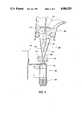
- FIG. 2is a diagrammatic side view of the four-roll sheet-inverter of the present invention that employs a low-rate compression spring
- the known apparatus shown in FIG. 1consists basically of means for holding a stack 2 of copy sheets adjacent to a feeder 4 for extracting a sheet from the top of the stack each time a copy is required.
- a feeder 4for extracting a sheet from the top of the stack each time a copy is required.
- Each sheet leaving feeder 4passes in non-sliding contact with a photoreceptor 6 (shown herein the form of a drum, although it could equally be a belt), from which a particulate material (toner) designed to present a visual contrast with the material of the sheet is transferred from the surface of the photoreceptor to the upper face of the respective sheet.
- tonerparticulate material
- Path 12is an output path, which leads to a feeder 16 ejecting each finished sheet into an output tray 18.
- a sheet deflected along path 42passes to the input nip 44 of a four-roll sheet inverter generally referenced 40.
- the sheet-feeder 40not only can simplex copies be inverted prior to their delivery to a buffer tray, but also duplex copies may be reinverted prior to delivery to an output tray, as well as simplex copies being inverted prior to delivery to a sorter which requires image-side-down copy orientation to ensure correct copy set collation.
- each pocketis provided with sheet-reversing means, so that after entering pocket 48, each sheet is forced upwardly so that it enters the right-hand nip 52, from which the sheet passes through feeder 32 to a buffer tray 34 where each sheet is engaged by a bottom-mounted feeder 36 which is effective to extract the sheet from tray 34 and turn it through a sufficient angle for its remaining blank side to come into contract with photoreceptor 6 in the manner similar to that described above in connection with FIG. 1.
- each sheet fed into pocket 50is forced upwardly so that its new lead edge becomes engaged by the left-hand nip 54, which is effective to feed the sheet to an output tray.
- the improved four roll inverter 100 of the present invention in FIG. 2includes a central input nip 110 and two exit nips 105 and 115.
- a diverter 120is positioned with a pointed end thereof extending upstream of input nip 110 and is adapted to deflect sheets against either sides 122 or 124 of inversion channel 125.
- Diverter 120is rotatably actuable by a conventional solenoid to move from the solid line position to the dotted line position as desired depending on whether a sheet is to travel out of the inversion channel to output tray 18 or to a location within the machine for further processing.
- Input nip 110drives sheets into corrugation nip 130 that includes reverse rotating retard rolls 134 and 137 that are positioned downstream of diverter 120 and within the inversion channel 125.
- the drive force of the input nip on each sheetis greater than the reverse drive force of the reverse rotating retard corrugation nip 130 and propels each sheet through two 8 mm steel rods 150 formed by side members 152 and 154 mounted on bracket 101 and running parallel and spaced 3 mm apart or into a series of hollow split tubes (not shown).
- a soft linear compression spring 160surrounds a portion of the rod pair or each hollow tube and acts as a backstop for the sheets. It appears that the lead edge of each sheet always stays below the local buckling load.
- the backstop assemblyincluding at least one hollow split tube and a compression spring is assembled such that the tube guides both the spring and the sheets.
- the outside diameter of the springis about 1 mm larger than the tube outside diameter to avoid the possibility of the spring locking on the tube when the sheet strikes the spring off-center.
- the narrow confinement experienced by the sheet as it moves through the guide space of the hollow split tubes or rodshas the effect of temporarily increasing the stiffness of the sheet and thus its buckling strength. Even then, it is somewhat surprising that with the spring acting as the sole backstop for sheets entering the inversion channel no sheet damage has been observed across all ranges of paper weights and sizes.
- nip 110After a sheet leaves input nip 110, it is urged back out of the inversion channel by spring 160 and driven by reverse rotating retard corrugation nip 130 toward either output nip 115 or nip 105 depending on which position diverter 120 is in at that time. If diverter 105 is in the dotted line position, nip 115 then captures the sheet and drives it toward output tray 18. However, if diverter 120 is in the solid line position nip 105 receives the sheet from corrugation nip 130 and transports the sheet toward duplex tray 34 for continued processing within the machine.
- an inverter apparatusincludes a four roll inverter in which a sheet is fed into the middle of the assembly and from which it can be fed out in two different directions/branches depending on the copying requirement.
- the inverterallows copying of 1 to N simplex documents into collated sets and N to 1 copying of simplex documents into duplex sets without document precount.
- Improved sheet controlis obtained with the use of a spring loaded inversion channel that confines the sheet in a narrow space which enhances the range of paper weights and sizes that the inverter is capable of handling.
Landscapes
- Engineering & Computer Science (AREA)
- Mechanical Engineering (AREA)
- Separation, Sorting, Adjustment, Or Bending Of Sheets To Be Conveyed (AREA)
- Delivering By Means Of Belts And Rollers (AREA)
Abstract
Description
Claims (20)
Priority Applications (5)
| Application Number | Priority Date | Filing Date | Title |
|---|---|---|---|
| US07/258,944US4986529A (en) | 1988-10-17 | 1988-10-17 | Four roll inverter |
| CA000615247ACA1328671C (en) | 1988-10-17 | 1989-09-29 | Four roll inverter |
| JP1264824AJPH02182660A (en) | 1988-10-17 | 1989-10-11 | Inversion apparatus |
| DE68916366TDE68916366T2 (en) | 1988-10-17 | 1989-10-17 | Sheet turner. |
| EP89310659AEP0365283B1 (en) | 1988-10-17 | 1989-10-17 | Sheet inverter |
Applications Claiming Priority (1)
| Application Number | Priority Date | Filing Date | Title |
|---|---|---|---|
| US07/258,944US4986529A (en) | 1988-10-17 | 1988-10-17 | Four roll inverter |
Publications (1)
| Publication Number | Publication Date |
|---|---|
| US4986529Atrue US4986529A (en) | 1991-01-22 |
Family
ID=22982791
Family Applications (1)
| Application Number | Title | Priority Date | Filing Date |
|---|---|---|---|
| US07/258,944Expired - Fee RelatedUS4986529A (en) | 1988-10-17 | 1988-10-17 | Four roll inverter |
Country Status (5)
| Country | Link |
|---|---|
| US (1) | US4986529A (en) |
| EP (1) | EP0365283B1 (en) |
| JP (1) | JPH02182660A (en) |
| CA (1) | CA1328671C (en) |
| DE (1) | DE68916366T2 (en) |
Cited By (24)
| Publication number | Priority date | Publication date | Assignee | Title |
|---|---|---|---|---|
| US5131649A (en)* | 1991-01-03 | 1992-07-21 | Xerox Corporation | Multiple output sheet inverter |
| US5228681A (en)* | 1991-11-22 | 1993-07-20 | E. I. Du Pont De Nemours And Company | Apparatus for diverting sheets |
| US5265864A (en)* | 1992-04-02 | 1993-11-30 | Xerox Corporation | Inverter with a friction/corrugating driver |
| US5386980A (en)* | 1994-03-16 | 1995-02-07 | Eastman Kodak Company | Image forming apparatus and sheet inverter providing increased sheet beam strength |
| US5396322A (en)* | 1993-11-05 | 1995-03-07 | Gradco (Japan) Ltd. | Single feed path dual sheet receiver |
| US5473419A (en)* | 1993-11-08 | 1995-12-05 | Eastman Kodak Company | Image forming apparatus having a duplex path with an inverter |
| US5604577A (en)* | 1994-04-27 | 1997-02-18 | Sharp Kabushiki Kaisha | Double-side image forming apparatus and reverse sheet feeding device |
| WO1998028214A1 (en)* | 1996-12-20 | 1998-07-02 | Bell & Howell Mail Processing Systems | Apparatus and method for selectively diverting sheets |
| US5927713A (en)* | 1997-09-18 | 1999-07-27 | Bell & Howell Mail Processing Systems | Apparatus and method for inverting, staging and diverting sheet articles |
| EP0892323A3 (en)* | 1997-07-14 | 2002-06-19 | Seiko Epson Corporation | Image forming apparatus |
| US6456310B1 (en) | 2000-12-11 | 2002-09-24 | Xerox Corporation | Bi-cell chevrons detection color registration system for color printing |
| US6474638B1 (en)* | 1998-12-22 | 2002-11-05 | Giesecke & Devrient Gmbh | Device for turning sheets |
| US20030071409A1 (en)* | 2001-09-28 | 2003-04-17 | Masaaki Sumi | Device for reversing direction of motion of paper sheet |
| US6644655B2 (en)* | 2000-09-20 | 2003-11-11 | Heidelberger Druckmaschinen Ag | Equipment for distributing flexible sheet-shaped objects |
| US6672583B2 (en)* | 2002-06-04 | 2004-01-06 | Lite-On Technology Corporation | Double-side automatic feeding apparatus |
| US20050035540A1 (en)* | 2003-08-12 | 2005-02-17 | Carter Daniel L. | Sensor and diverter mechanism for an image forming apparatus |
| US20050051949A1 (en)* | 2003-08-12 | 2005-03-10 | Carter Daniel L. | Image forming device having a sensor with two separate distinguishable triggers |
| US20050189712A1 (en)* | 2004-03-01 | 2005-09-01 | Carter Daniel L. | Dual path roll for an image forming device |
| US20050254872A1 (en)* | 2004-05-11 | 2005-11-17 | Manabu Nonaka | Method and apparatus for image forming |
| US20090108517A1 (en)* | 2007-10-26 | 2009-04-30 | Daniel Guerand | Movable Gate With Fluid Damper For Directing Media Sheets Within An Image Forming Apparatus |
| US20110049784A1 (en)* | 2009-08-27 | 2011-03-03 | Xerox Corporation | Sheet buffering system |
| US20110062661A1 (en)* | 2009-09-14 | 2011-03-17 | Fuji Xerox Co., Ltd. | Medium-directing device and image-forming apparatus |
| US20160116881A1 (en)* | 2014-10-24 | 2016-04-28 | Seiko Epson Corporation | Medium transport unit, recording apparatus, and image reading apparatus |
| US11090952B2 (en) | 2014-10-24 | 2021-08-17 | Seiko Epson Corporation | Medium transport unit, recording apparatus, and image reading apparatus |
Citations (12)
| Publication number | Priority date | Publication date | Assignee | Title |
|---|---|---|---|---|
| US2484196A (en)* | 1945-03-03 | 1949-10-11 | Hoe & Co R | Machine for separating and feeding counted batches of articles |
| US4078789A (en)* | 1977-01-21 | 1978-03-14 | Kittredge Lloyd G | Document inverter |
| US4238126A (en)* | 1979-08-31 | 1980-12-09 | Xerox Corporation | Recirculating simplex/duplex document handler |
| US4277061A (en)* | 1977-12-23 | 1981-07-07 | Agfa-Gevaert, A.G. | Apparatus for classifying photographic prints or the like |
| US4359217A (en)* | 1980-09-02 | 1982-11-16 | Xerox Corporation | Inverter with proportional force paper drive |
| US4385825A (en)* | 1978-05-16 | 1983-05-31 | Ricoh Co., Ltd. | Copying apparatus |
| US4441704A (en)* | 1980-12-05 | 1984-04-10 | Luarel Bank Machine Co., Ltd. | Three direction changeable guide device for use in a bank note handling machine |
| US4487506A (en)* | 1982-08-23 | 1984-12-11 | Xerox Corporation | Reversing roll inverter with bypass capability |
| US4512255A (en)* | 1983-03-04 | 1985-04-23 | Am International | Sheet handling mechanism for duplicating machine with duplexing capability |
| US4673176A (en)* | 1980-10-02 | 1987-06-16 | Xerox Corporation | Soft nip damping inverter |
| US4699367A (en)* | 1986-02-24 | 1987-10-13 | Eastman Kodak Company | Sheet turnover mechanism |
| US4735409A (en)* | 1986-02-10 | 1988-04-05 | Xerox Corporation | Sheet feeders |
Family Cites Families (3)
| Publication number | Priority date | Publication date | Assignee | Title |
|---|---|---|---|---|
| DE1146449B (en)* | 1960-08-19 | 1963-03-28 | Telefunken Patent | Device for reversing the motion of rectangular, flat conveyed material |
| US4262895A (en)* | 1979-08-31 | 1981-04-21 | Xerox Corporation | Inverter with variable buckling control |
| JPS58152799A (en)* | 1982-03-05 | 1983-09-10 | 株式会社豊田自動織機製作所 | Wide-range type clamping device |
- 1988
- 1988-10-17USUS07/258,944patent/US4986529A/ennot_activeExpired - Fee Related
- 1989
- 1989-09-29CACA000615247Apatent/CA1328671C/ennot_activeExpired - Fee Related
- 1989-10-11JPJP1264824Apatent/JPH02182660A/enactivePending
- 1989-10-17DEDE68916366Tpatent/DE68916366T2/ennot_activeExpired - Fee Related
- 1989-10-17EPEP89310659Apatent/EP0365283B1/ennot_activeExpired - Lifetime
Patent Citations (12)
| Publication number | Priority date | Publication date | Assignee | Title |
|---|---|---|---|---|
| US2484196A (en)* | 1945-03-03 | 1949-10-11 | Hoe & Co R | Machine for separating and feeding counted batches of articles |
| US4078789A (en)* | 1977-01-21 | 1978-03-14 | Kittredge Lloyd G | Document inverter |
| US4277061A (en)* | 1977-12-23 | 1981-07-07 | Agfa-Gevaert, A.G. | Apparatus for classifying photographic prints or the like |
| US4385825A (en)* | 1978-05-16 | 1983-05-31 | Ricoh Co., Ltd. | Copying apparatus |
| US4238126A (en)* | 1979-08-31 | 1980-12-09 | Xerox Corporation | Recirculating simplex/duplex document handler |
| US4359217A (en)* | 1980-09-02 | 1982-11-16 | Xerox Corporation | Inverter with proportional force paper drive |
| US4673176A (en)* | 1980-10-02 | 1987-06-16 | Xerox Corporation | Soft nip damping inverter |
| US4441704A (en)* | 1980-12-05 | 1984-04-10 | Luarel Bank Machine Co., Ltd. | Three direction changeable guide device for use in a bank note handling machine |
| US4487506A (en)* | 1982-08-23 | 1984-12-11 | Xerox Corporation | Reversing roll inverter with bypass capability |
| US4512255A (en)* | 1983-03-04 | 1985-04-23 | Am International | Sheet handling mechanism for duplicating machine with duplexing capability |
| US4735409A (en)* | 1986-02-10 | 1988-04-05 | Xerox Corporation | Sheet feeders |
| US4699367A (en)* | 1986-02-24 | 1987-10-13 | Eastman Kodak Company | Sheet turnover mechanism |
Non-Patent Citations (4)
| Title |
|---|
| IBM Technical Disclosure Bulletin, P. S. Bach, "Sheet Inverter", vol. 18, No. 3, Aug. 1975, pp. 628 and 629. |
| IBM Technical Disclosure Bulletin, P. S. Bach, Sheet Inverter , vol. 18, No. 3, Aug. 1975, pp. 628 and 629.* |
| Xerox Disclosure Journal, George J. Roller, "Constant Force Spring Inverter", vol. 8, No. 2, Mar./Apr., 1983, p. 101. |
| Xerox Disclosure Journal, George J. Roller, Constant Force Spring Inverter , vol. 8, No. 2, Mar./Apr., 1983, p. 101.* |
Cited By (40)
| Publication number | Priority date | Publication date | Assignee | Title |
|---|---|---|---|---|
| US5131649A (en)* | 1991-01-03 | 1992-07-21 | Xerox Corporation | Multiple output sheet inverter |
| US5228681A (en)* | 1991-11-22 | 1993-07-20 | E. I. Du Pont De Nemours And Company | Apparatus for diverting sheets |
| US5265864A (en)* | 1992-04-02 | 1993-11-30 | Xerox Corporation | Inverter with a friction/corrugating driver |
| US5396322A (en)* | 1993-11-05 | 1995-03-07 | Gradco (Japan) Ltd. | Single feed path dual sheet receiver |
| EP0659668A3 (en)* | 1993-11-08 | 1998-09-23 | Eastman Kodak Company | Image forming apparatus having a duplex path with an inverter |
| US5473419A (en)* | 1993-11-08 | 1995-12-05 | Eastman Kodak Company | Image forming apparatus having a duplex path with an inverter |
| US5386980A (en)* | 1994-03-16 | 1995-02-07 | Eastman Kodak Company | Image forming apparatus and sheet inverter providing increased sheet beam strength |
| US5604577A (en)* | 1994-04-27 | 1997-02-18 | Sharp Kabushiki Kaisha | Double-side image forming apparatus and reverse sheet feeding device |
| WO1998028214A1 (en)* | 1996-12-20 | 1998-07-02 | Bell & Howell Mail Processing Systems | Apparatus and method for selectively diverting sheets |
| US5794931A (en)* | 1996-12-20 | 1998-08-18 | Bell & Howell Mail Processing Systems | Guide apparatus and method for selectively guiding sheets into a predetermined path |
| GB2334951A (en)* | 1996-12-20 | 1999-09-08 | Bell & Howell Mail Proc Sys Co | Apparatus and method for selectively diverting sheets |
| GB2334951B (en)* | 1996-12-20 | 2001-10-31 | Bell & Howell Mail Proc System | Apparatus and method for selectively diverting sheets |
| EP0892323A3 (en)* | 1997-07-14 | 2002-06-19 | Seiko Epson Corporation | Image forming apparatus |
| US5927713A (en)* | 1997-09-18 | 1999-07-27 | Bell & Howell Mail Processing Systems | Apparatus and method for inverting, staging and diverting sheet articles |
| US6474638B1 (en)* | 1998-12-22 | 2002-11-05 | Giesecke & Devrient Gmbh | Device for turning sheets |
| US6644655B2 (en)* | 2000-09-20 | 2003-11-11 | Heidelberger Druckmaschinen Ag | Equipment for distributing flexible sheet-shaped objects |
| US6456310B1 (en) | 2000-12-11 | 2002-09-24 | Xerox Corporation | Bi-cell chevrons detection color registration system for color printing |
| US20030071409A1 (en)* | 2001-09-28 | 2003-04-17 | Masaaki Sumi | Device for reversing direction of motion of paper sheet |
| US6769682B2 (en)* | 2001-09-28 | 2004-08-03 | Omron Corporation | Device for reversing direction of motion of paper sheet |
| US6672583B2 (en)* | 2002-06-04 | 2004-01-06 | Lite-On Technology Corporation | Double-side automatic feeding apparatus |
| US20050035540A1 (en)* | 2003-08-12 | 2005-02-17 | Carter Daniel L. | Sensor and diverter mechanism for an image forming apparatus |
| US20050051949A1 (en)* | 2003-08-12 | 2005-03-10 | Carter Daniel L. | Image forming device having a sensor with two separate distinguishable triggers |
| US6926272B2 (en) | 2003-08-12 | 2005-08-09 | Lexmark International, Inc. | Sensor and diverter mechanism for an image forming apparatus |
| US7021622B2 (en) | 2003-08-12 | 2006-04-04 | Lexmark International, Inc. | Image forming device having a sensor with two separate distinguishable triggers |
| US20050189712A1 (en)* | 2004-03-01 | 2005-09-01 | Carter Daniel L. | Dual path roll for an image forming device |
| US7431293B2 (en) | 2004-03-01 | 2008-10-07 | Carter Daniel L | Dual path roll for an image forming device |
| US20050254872A1 (en)* | 2004-05-11 | 2005-11-17 | Manabu Nonaka | Method and apparatus for image forming |
| US7418235B2 (en)* | 2004-05-11 | 2008-08-26 | Ricoh Company, Ltd. | Method and apparatus for image forming |
| US7762552B2 (en) | 2007-10-26 | 2010-07-27 | Lexmark International, Inc. | Movable gate with fluid damper for directing media sheets within an image forming apparatus |
| US20090108517A1 (en)* | 2007-10-26 | 2009-04-30 | Daniel Guerand | Movable Gate With Fluid Damper For Directing Media Sheets Within An Image Forming Apparatus |
| US20110049784A1 (en)* | 2009-08-27 | 2011-03-03 | Xerox Corporation | Sheet buffering system |
| US7992854B2 (en)* | 2009-08-27 | 2011-08-09 | Xerox Corporation | Sheet buffering system |
| US20110062661A1 (en)* | 2009-09-14 | 2011-03-17 | Fuji Xerox Co., Ltd. | Medium-directing device and image-forming apparatus |
| US8231126B2 (en)* | 2009-09-14 | 2012-07-31 | Fuji Xerox Co., Ltd. | Medium-directing device and image-forming apparatus |
| US20160116881A1 (en)* | 2014-10-24 | 2016-04-28 | Seiko Epson Corporation | Medium transport unit, recording apparatus, and image reading apparatus |
| US9442448B2 (en)* | 2014-10-24 | 2016-09-13 | Seiko Epson Corporation | Medium transport unit, recording apparatus, and image reading apparatus |
| US9855770B2 (en) | 2014-10-24 | 2018-01-02 | Seiko Epson Corporation | Medium transport unit, recording apparatus, and image reading apparatus |
| US10391791B2 (en) | 2014-10-24 | 2019-08-27 | Seiko Epson Corporation | Medium transport unit, recording apparatus, and image reading apparatus |
| US11090952B2 (en) | 2014-10-24 | 2021-08-17 | Seiko Epson Corporation | Medium transport unit, recording apparatus, and image reading apparatus |
| US11661298B2 (en) | 2014-10-24 | 2023-05-30 | Seiko Epson Corporation | Medium transport unit, recording apparatus, and image reading apparatus |
Also Published As
| Publication number | Publication date |
|---|---|
| CA1328671C (en) | 1994-04-19 |
| EP0365283A3 (en) | 1990-07-04 |
| EP0365283B1 (en) | 1994-06-22 |
| DE68916366D1 (en) | 1994-07-28 |
| JPH02182660A (en) | 1990-07-17 |
| EP0365283A2 (en) | 1990-04-25 |
| DE68916366T2 (en) | 1995-01-19 |
Similar Documents
| Publication | Publication Date | Title |
|---|---|---|
| US4986529A (en) | Four roll inverter | |
| US4359217A (en) | Inverter with proportional force paper drive | |
| EP0030069B1 (en) | Sheet inverter and method of reversing the direction of sheets | |
| US4346880A (en) | Apparatus for inverting substrates | |
| US5265864A (en) | Inverter with a friction/corrugating driver | |
| US5358231A (en) | Sheet handling system having a sheet corrugation nip | |
| EP0613846B1 (en) | Device for conveying sheets with rolls | |
| JPH06227723A (en) | Disk type stacking system | |
| US4673176A (en) | Soft nip damping inverter | |
| GB1605090A (en) | Document handling | |
| US4842263A (en) | Sheet reversing apparatus | |
| US5374049A (en) | Compact inverter | |
| EP0047181B1 (en) | A substrate inverter | |
| US5449160A (en) | Gateless rocker inverter | |
| US4735409A (en) | Sheet feeders | |
| US6808171B2 (en) | Inverter having a slow speed drive mode for improved reliability | |
| US5447303A (en) | Sheet inverter apparatus | |
| US6186497B1 (en) | Low cost multiple output sheet inverter | |
| US5449163A (en) | Full productivity high performance inverter | |
| US5102116A (en) | Friction retard feeder with a concave retard pad | |
| US4842262A (en) | Document inverter | |
| US5269505A (en) | Friction retard feeder with a stepped retard pad | |
| JPH02223964A (en) | Copying machine with paper shifting mechanism for copying | |
| GB2168688A (en) | Sheet inverter | |
| CA1178304A (en) | Retard drive inverter |
Legal Events
| Date | Code | Title | Description |
|---|---|---|---|
| AS | Assignment | Owner name:XEROX CORPORATION, STAMFORD, CT A CORP. OF NY Free format text:ASSIGNMENT OF ASSIGNORS INTEREST.;ASSIGNOR:DIXON, BARRY M.;REEL/FRAME:004985/0307 Effective date:19880930 Owner name:XEROX CORPORATION, STAMFORD, CT A CORP. OF NY Free format text:ASSIGNMENT OF ASSIGNORS INTEREST.;ASSIGNOR:AGARWAL, VINOD K.;REEL/FRAME:004985/0308 Effective date:19880921 Owner name:XEROX CORPORATION, STAMFORD, CT A CORP. OF NY Free format text:ASSIGNMENT OF ASSIGNORS INTEREST.;ASSIGNOR:JONES, GREGORY G.;REEL/FRAME:004985/0309 Effective date:19880921 Owner name:XEROX CORPORATION, STAMFORD, CT A CORP. OF NY Free format text:ASSIGNMENT OF ASSIGNORS INTEREST.;ASSIGNOR:FOERSTER, JOSEPH C.;REEL/FRAME:004985/0310 Effective date:19880920 Owner name:XEROX CORPORATION, A CORP. OF NY, CONNECTICUT Free format text:ASSIGNMENT OF ASSIGNORS INTEREST;ASSIGNOR:DIXON, BARRY M.;REEL/FRAME:004985/0307 Effective date:19880930 Owner name:XEROX CORPORATION, A CORP. OF NY, CONNECTICUT Free format text:ASSIGNMENT OF ASSIGNORS INTEREST;ASSIGNOR:AGARWAL, VINOD K.;REEL/FRAME:004985/0308 Effective date:19880921 Owner name:XEROX CORPORATION, A CORP. OF NY, CONNECTICUT Free format text:ASSIGNMENT OF ASSIGNORS INTEREST;ASSIGNOR:JONES, GREGORY G.;REEL/FRAME:004985/0309 Effective date:19880921 Owner name:XEROX CORPORATION, A CORP. OF NY, CONNECTICUT Free format text:ASSIGNMENT OF ASSIGNORS INTEREST;ASSIGNOR:FOERSTER, JOSEPH C.;REEL/FRAME:004985/0310 Effective date:19880920 | |
| FEPP | Fee payment procedure | Free format text:PAYOR NUMBER ASSIGNED (ORIGINAL EVENT CODE: ASPN); ENTITY STATUS OF PATENT OWNER: LARGE ENTITY | |
| FPAY | Fee payment | Year of fee payment:4 | |
| REMI | Maintenance fee reminder mailed | ||
| LAPS | Lapse for failure to pay maintenance fees | ||
| FP | Lapsed due to failure to pay maintenance fee | Effective date:19990122 | |
| STCH | Information on status: patent discontinuation | Free format text:PATENT EXPIRED DUE TO NONPAYMENT OF MAINTENANCE FEES UNDER 37 CFR 1.362 |