US4984248A - High speed transceiver - Google Patents
High speed transceiverDownload PDFInfo
- Publication number
- US4984248A US4984248AUS07/234,227US23422788AUS4984248AUS 4984248 AUS4984248 AUS 4984248AUS 23422788 AUS23422788 AUS 23422788AUS 4984248 AUS4984248 AUS 4984248A
- Authority
- US
- United States
- Prior art keywords
- communicating medium
- data
- transceiver
- data communication
- communicating
- Prior art date
- Legal status (The legal status is an assumption and is not a legal conclusion. Google has not performed a legal analysis and makes no representation as to the accuracy of the status listed.)
- Expired - Fee Related
Links
- 238000004891communicationMethods0.000claimsabstractdescription18
- 238000002955isolationMethods0.000claimsabstract6
- 239000003990capacitorSubstances0.000claimsdescription14
- 230000004913activationEffects0.000claims1
- 230000001960triggered effectEffects0.000claims1
- 238000012546transferMethods0.000abstractdescription3
- 238000006243chemical reactionMethods0.000abstract1
- 230000035939shockEffects0.000abstract1
- 238000010586diagramMethods0.000description7
- 230000000694effectsEffects0.000description7
- 239000004020conductorSubstances0.000description5
- 238000000034methodMethods0.000description5
- 230000005540biological transmissionEffects0.000description4
- 230000008878couplingEffects0.000description4
- 238000010168coupling processMethods0.000description4
- 238000005859coupling reactionMethods0.000description4
- 230000008901benefitEffects0.000description3
- 238000001514detection methodMethods0.000description2
- 230000001629suppressionEffects0.000description2
- 230000009471actionEffects0.000description1
- 230000000903blocking effectEffects0.000description1
- 230000004069differentiationEffects0.000description1
- 230000005670electromagnetic radiationEffects0.000description1
- 238000012986modificationMethods0.000description1
- 230000004048modificationEffects0.000description1
- 238000012544monitoring processMethods0.000description1
- 230000001105regulatory effectEffects0.000description1
- 230000004044responseEffects0.000description1
Images


Classifications
- H—ELECTRICITY
- H04—ELECTRIC COMMUNICATION TECHNIQUE
- H04B—TRANSMISSION
- H04B15/00—Suppression or limitation of noise or interference
- H04B15/02—Reducing interference from electric apparatus by means located at or near the interfering apparatus
- H—ELECTRICITY
- H04—ELECTRIC COMMUNICATION TECHNIQUE
- H04B—TRANSMISSION
- H04B3/00—Line transmission systems
- H04B3/02—Details
- H04B3/28—Reducing interference caused by currents induced in cable sheathing or armouring
Definitions
- the present inventionrelates to a data communications transceiver used for base band packet switching, such as an Ethernet system.
- a transceiver such as is used with an Ethernet systemis generally disclosed in U.S. Pat. No. 4,317,205 of Tat C. Lam for a "Wideband Transceiver With EMI Suppression", granted Feb. 23, 1982.
- the transmitter sectionis either capacitor coupled or transformer coupled to the communicating medium which medium is most commonly a shielded coaxial cable.
- Both methods of couplinguse a regulated voltage source or emitter-coupled logic circuitry to drive the coaxial cable as found, for example, in U.S. Pat. No. 4,412,347 of Jesse B. Lipcon entitled "Precision Setting of Currents and Reference Voltages", granted Oct. 25, 1983.
- the voltage level of the signalwill affect the skew of the received data. Noise or reflection on the transmission line can be coupled to the receiver which in turn will be received as an unwanted signal.
- the capacitive AC couplingwill limit the low frequency data to the extent of the differentiation being used by the coupling.
- Another problemis that when the transceiver is transmitting, electromagnetic interference may be present around the connection between the connector to the shielded cable and the shielded container of the transceiver. This electromagnetic interference is believed to be due to stray capacitance between the center conductor of the connector and the shielded container.
- a conventional way to minimize this effectis to shield the exposed center conductor or to make the outer connector much more capacitive relative to the shielded container than to the center conductor. This can produce switching spikes, which cause unwanted interference in the atmosphere around the transceiver because of high speed switching and this AC coupling to ground.
- Still another problemoccurs where the transmission medium is DC coupled. The capacitance effect of the transmitter is passed to the coaxial cable, loading the communicating medium. This is found in U.S. Pat. No. 4,384,363 of Jesse B. Lipcon entitled "Transceiver For Local Network Using Carrier-Sense Multiple Access/Collision Detection", granted May 17, 1983.
- the transceiverthere are means for suppressing electromagnetic interference when transmitting data to the communicating medium.
- This electromagnetic interferenceis suppressed by means of a capacitor which is shunted with the input of a differential amplifier.
- the capacitorlimits the bandwidth of transfer data by suppressing the higher order harmonic of the square wave input signals. In this way, the high frequency noise and the harmonic of the transmission data are filtered out by the capacitor which capacitor is sometimes called a rise time limit capacitor or suppression capacitor.
- the transmitting datatravels on the coaxial cable by fundamental wave. It has an advantage of allowing transmission over a greater distance and causing less electromagnetic radiation.
- a constant current sourceis employed in the connection to the transmitting circuitry. It differs from the previously mentioned method of voltage driving, using current driving to reduce the electromagnetic interference and having a greater driving distance in the coaxial cable.
- the collision detectormonitors the DC level on the coaxial cable. In this way, collisions can be detected quickly and reliably.
- FIG. 1shows relative location and connections between a transceiver of the present invention connected to data terminal equipment and a communicating medium
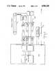
- FIG. 2is a block diagram of a transceiver of the present invention
- FIG. 3is a more detailed circuit diagram of the transceiver depicted in the block diagram of FIG. 2;
- FIGS. 4A and 4Bare illustrations of the theory of current drive and collision detecting methods with FIG. 4A depicting a coaxial cable with two terminators and FIG. 4B depicting a circuit equivalent of FIG. 4A;
- FIG. 5is a detailed circuit diagram of the portion of the transmitter showing a differential driver with a constant current source.
- FIG. lthere is shown a data communication transceiver 10 connected between data terminal equipment 11 and the communicating medium, here shown as a coaxial cable 12.
- a data communication transceiver 10consists of four parts, which are a transmitter 20, a receiver 21, a collision detector 22, and a DC to DC converter 23.
- the output of the differential amplifier A1is coupled to a differential driver 31 which consists of two transistors Q1 and Q2 and one constant current source 32.
- Resistors R2 and R3limit the input current of the differential driver 31.
- Capacitors C2 and C3, in parallel with resistors R2 and R3 respectively,can speed up the response of the differential driver 31.
- a rise time limiting or suppressor capacitor C1limits the transfer data signal by suppressing the higher order harmonic of the square wave input signals to the differential driver 31.
- transistors Q1 and Q2are alternately “on” or “off” according to the input data signal.
- a dummy load R1is applied to the collector of transistor Q2.
- Two diodes D1 and D2are connected to the collector of transistor Q1. Since the P-N junction of the serially connected diodes D1 and D2 acts as serially connected capacitors, the capacitance effect of the transmitter 20 is reduced.
- FIG. 4Athere is shown a segment of coaxial cable with two terminators on each end of the coaxial cable.
- FIG. 4Bis an equivalent circuit of FIG. 4A.
- the two 50 ohm terminators of FIG. 4Aare shunted on each end of the coaxial cable, shown as the equivalent value of 25 ohms in FIG. 4B extending from the center conductor to the shield of the coaxial cable.
- the transmitter 20drives the coaxial cable 12 using a device of constant current source 32, the voltage drop appears on the 25 ohm resistor, so that the voltage source appears located on the two ends of the coaxial cable 12, with the advantage that operation is independent of the distance between transmitting and receiving stations.
- a collisionwill occur at anytime that, at the same time, more than one station transmits data to the coaxial cable.
- the total currentwill be the sum of all output current of the transmitters, as shown in the diagram of FIG. 4B.
- the voltage difference between the center conductor and the shield of the coaxial cableis larger than in the normal condition. A collision is easily detected by monitoring the DC level of the coaxial cable.
- the lowest path designated by CLis the collision path in the circuitry.
- a high speed comparator 41compares the incoming voltage on collision path CL with a reference voltage 42. When the incoming voltage is more negative than the reference voltage 42, a collision is designated. The output of the comparator triggers the 10 MHz. oscillator 43 to action to report this collision. This signal and both transmitter and receiver signals must pass through pulse transformers, T3 for the collision path CL, T1 for the transmitter path TX, and T2 for the receiver path RX, for connecting the communicating medium, coaxial cable 12 to data terminal equipment 11. If the incoming voltage on collision path CL is higher than the reference voltage 42, no collision is designated.
Landscapes
- Engineering & Computer Science (AREA)
- Computer Networks & Wireless Communication (AREA)
- Signal Processing (AREA)
- Small-Scale Networks (AREA)
Abstract
Description
Claims (9)
Priority Applications (2)
| Application Number | Priority Date | Filing Date | Title |
|---|---|---|---|
| US07/234,227US4984248A (en) | 1988-08-19 | 1988-08-19 | High speed transceiver |
| JP1138993AJPH0771093B2 (en) | 1988-08-19 | 1989-05-31 | Data communication transceiver |
Applications Claiming Priority (1)
| Application Number | Priority Date | Filing Date | Title |
|---|---|---|---|
| US07/234,227US4984248A (en) | 1988-08-19 | 1988-08-19 | High speed transceiver |
Publications (1)
| Publication Number | Publication Date |
|---|---|
| US4984248Atrue US4984248A (en) | 1991-01-08 |
Family
ID=22880476
Family Applications (1)
| Application Number | Title | Priority Date | Filing Date |
|---|---|---|---|
| US07/234,227Expired - Fee RelatedUS4984248A (en) | 1988-08-19 | 1988-08-19 | High speed transceiver |
Country Status (2)
| Country | Link |
|---|---|
| US (1) | US4984248A (en) |
| JP (1) | JPH0771093B2 (en) |
Cited By (9)
| Publication number | Priority date | Publication date | Assignee | Title |
|---|---|---|---|---|
| US5124982A (en)* | 1990-02-27 | 1992-06-23 | Allied Telesis, Incorporated | Multiple port medium attachment unit for a network |
| US5305350A (en)* | 1990-06-08 | 1994-04-19 | Chipcom Corporation | Multimedia high speed network |
| WO1995017723A1 (en)* | 1993-12-22 | 1995-06-29 | Tut Systems, Inc. | Enhanced collision detection for ethernet network |
| US5429442A (en)* | 1992-03-05 | 1995-07-04 | International Business Machines Corp. | Print hammer coil current control |
| US5960035A (en)* | 1995-09-29 | 1999-09-28 | Motorola Inc. | Method and apparatus for load balancing for a processor operated data communications device |
| US20050063477A1 (en)* | 2002-03-04 | 2005-03-24 | Allan Olson | Transmitter/receiver for bidirectional communications |
| US20110228816A1 (en)* | 1995-01-04 | 2011-09-22 | Interdigital Technology Corporation | Setting a transmission power level for a mobile unit |
| US20150263467A1 (en)* | 1998-04-10 | 2015-09-17 | Chrimar Systems, Inc. | Ethernet device |
| US9663254B2 (en) | 2011-12-19 | 2017-05-30 | Multivac Sepp Haggenmueller Se & Co. Kg | Method and folding device for handling L-boards |
Citations (8)
| Publication number | Priority date | Publication date | Assignee | Title |
|---|---|---|---|---|
| US3742450A (en)* | 1971-05-12 | 1973-06-26 | Bell Telephone Labor Inc | Isolating power supply for communication loop |
| US3872391A (en)* | 1974-01-16 | 1975-03-18 | Bell Telephone Labor Inc | Balanced line driver |
| US4317205A (en)* | 1980-06-13 | 1982-02-23 | Tcl, Inc. | Wideband transceiver with EMI suppression |
| US4337465A (en)* | 1980-09-25 | 1982-06-29 | Burroughs Corporation | Line driver circuit for a local area contention network |
| US4384363A (en)* | 1981-05-26 | 1983-05-17 | Digital Equipment Corporation | Transceiver for local network using carrier-sense multiple access/collision detection |
| US4412347A (en)* | 1981-05-26 | 1983-10-25 | Digital Equipment Corporation | Precision setting of currents and reference voltages |
| US4425663A (en)* | 1980-06-13 | 1984-01-10 | Tcl, Inc. | Low input capacitance data network transceiver |
| US4479228A (en)* | 1981-03-11 | 1984-10-23 | 3Com Corporation | Local computer network transceiver |
Family Cites Families (4)
| Publication number | Priority date | Publication date | Assignee | Title |
|---|---|---|---|---|
| JPS5429048B2 (en)* | 1973-07-17 | 1979-09-20 | ||
| JPS56169458A (en)* | 1980-05-30 | 1981-12-26 | Hitachi Ltd | Pulse signal transmission and reception circuit |
| JPS60242754A (en)* | 1984-05-16 | 1985-12-02 | Nec Corp | Pulse transformer drive circuit |
| JPS62146040A (en)* | 1985-12-20 | 1987-06-30 | Matsushita Electric Ind Co Ltd | Pair cable network system for home bus system |
- 1988
- 1988-08-19USUS07/234,227patent/US4984248A/ennot_activeExpired - Fee Related
- 1989
- 1989-05-31JPJP1138993Apatent/JPH0771093B2/ennot_activeExpired - Lifetime
Patent Citations (8)
| Publication number | Priority date | Publication date | Assignee | Title |
|---|---|---|---|---|
| US3742450A (en)* | 1971-05-12 | 1973-06-26 | Bell Telephone Labor Inc | Isolating power supply for communication loop |
| US3872391A (en)* | 1974-01-16 | 1975-03-18 | Bell Telephone Labor Inc | Balanced line driver |
| US4317205A (en)* | 1980-06-13 | 1982-02-23 | Tcl, Inc. | Wideband transceiver with EMI suppression |
| US4425663A (en)* | 1980-06-13 | 1984-01-10 | Tcl, Inc. | Low input capacitance data network transceiver |
| US4337465A (en)* | 1980-09-25 | 1982-06-29 | Burroughs Corporation | Line driver circuit for a local area contention network |
| US4479228A (en)* | 1981-03-11 | 1984-10-23 | 3Com Corporation | Local computer network transceiver |
| US4384363A (en)* | 1981-05-26 | 1983-05-17 | Digital Equipment Corporation | Transceiver for local network using carrier-sense multiple access/collision detection |
| US4412347A (en)* | 1981-05-26 | 1983-10-25 | Digital Equipment Corporation | Precision setting of currents and reference voltages |
Cited By (12)
| Publication number | Priority date | Publication date | Assignee | Title |
|---|---|---|---|---|
| US5124982A (en)* | 1990-02-27 | 1992-06-23 | Allied Telesis, Incorporated | Multiple port medium attachment unit for a network |
| US5305350A (en)* | 1990-06-08 | 1994-04-19 | Chipcom Corporation | Multimedia high speed network |
| US5429442A (en)* | 1992-03-05 | 1995-07-04 | International Business Machines Corp. | Print hammer coil current control |
| WO1995017723A1 (en)* | 1993-12-22 | 1995-06-29 | Tut Systems, Inc. | Enhanced collision detection for ethernet network |
| US5450594A (en)* | 1993-12-22 | 1995-09-12 | Tut Systems, Inc. | Enhanced collision detection for ethernet network |
| US20110228816A1 (en)* | 1995-01-04 | 2011-09-22 | Interdigital Technology Corporation | Setting a transmission power level for a mobile unit |
| US5960035A (en)* | 1995-09-29 | 1999-09-28 | Motorola Inc. | Method and apparatus for load balancing for a processor operated data communications device |
| US20150263467A1 (en)* | 1998-04-10 | 2015-09-17 | Chrimar Systems, Inc. | Ethernet device |
| US9812825B2 (en)* | 1998-04-10 | 2017-11-07 | Chrimar Systems, Inc. | Ethernet device |
| US20050063477A1 (en)* | 2002-03-04 | 2005-03-24 | Allan Olson | Transmitter/receiver for bidirectional communications |
| US7221702B2 (en)* | 2002-03-04 | 2007-05-22 | Infineon Technologies Ag | Transmitter/receiver for bidirectional communications |
| US9663254B2 (en) | 2011-12-19 | 2017-05-30 | Multivac Sepp Haggenmueller Se & Co. Kg | Method and folding device for handling L-boards |
Also Published As
| Publication number | Publication date |
|---|---|
| JPH02113647A (en) | 1990-04-25 |
| JPH0771093B2 (en) | 1995-07-31 |
Similar Documents
| Publication | Publication Date | Title |
|---|---|---|
| US4479228A (en) | Local computer network transceiver | |
| EP0302162B1 (en) | Apparatus for matching unbalanced R.F. baseband signals to balanced signals on a twisted two-wire line | |
| US6175556B1 (en) | Remote powered ethernet repeater | |
| US5253249A (en) | Bidirectional transceiver for high speed data system | |
| US5533054A (en) | Multi-level data transmitter | |
| US4641378A (en) | Fiber optic communication module | |
| US5321372A (en) | Apparatus and method for terminating cables to minimize emissions and susceptibility | |
| EP3526903B1 (en) | Coaxial data communication with reduced emi | |
| US4984248A (en) | High speed transceiver | |
| US8363705B2 (en) | Differential driver with common mode voltage tracking and method | |
| JPH02277338A (en) | Station locator for rocal area network | |
| US4435764A (en) | Computer network having a single electrically continuous bi-directional bus | |
| US5450594A (en) | Enhanced collision detection for ethernet network | |
| US5125006A (en) | Local area network high impedance transceiver | |
| US5124982A (en) | Multiple port medium attachment unit for a network | |
| JPS6343444A (en) | Local area network with multinode bus topology | |
| CA1192643A (en) | Wideband transceiver with emi suppression | |
| JPH07240757A (en) | System and method for increasing capacitance of existing local area network using shield stranded wire pair | |
| US4682344A (en) | Rf fsk transmitter | |
| US4908530A (en) | Non-linear squelch circuit for IEEE-802. 3 protocol | |
| US4317205A (en) | Wideband transceiver with EMI suppression | |
| US6714558B1 (en) | System for implementing network protocols between devices on a printed circuit board | |
| JPH0514240A (en) | Signal transmission circuit | |
| EP0271179B1 (en) | Daisy chain collision detection circuit | |
| US5317560A (en) | Star data network with logical ring function preferably using token access |
Legal Events
| Date | Code | Title | Description |
|---|---|---|---|
| AS | Assignment | Owner name:INDUSTRIAL TECHNOLOGY RESEARCH INSTITUTE, NO. 195- Free format text:ASSIGNMENT OF ASSIGNORS INTEREST.;ASSIGNOR:HONG, HEI-TAI;REEL/FRAME:004975/0268 Effective date:19880916 Owner name:INDUSTRIAL TECHNOLOGY RESEARCH INSTITUTE, REP. OF Free format text:ASSIGNMENT OF ASSIGNORS INTEREST;ASSIGNOR:HONG, HEI-TAI;REEL/FRAME:004975/0268 Effective date:19880916 | |
| FEPP | Fee payment procedure | Free format text:PAYOR NUMBER ASSIGNED (ORIGINAL EVENT CODE: ASPN); ENTITY STATUS OF PATENT OWNER: LARGE ENTITY | |
| FEPP | Fee payment procedure | Free format text:PAT HLDR NO LONGER CLAIMS SMALL ENT STAT AS SMALL BUSINESS (ORIGINAL EVENT CODE: LSM2); ENTITY STATUS OF PATENT OWNER: LARGE ENTITY | |
| FPAY | Fee payment | Year of fee payment:4 | |
| FPAY | Fee payment | Year of fee payment:8 | |
| REMI | Maintenance fee reminder mailed | ||
| LAPS | Lapse for failure to pay maintenance fees | ||
| LAPS | Lapse for failure to pay maintenance fees | Free format text:PATENT EXPIRED FOR FAILURE TO PAY MAINTENANCE FEES (ORIGINAL EVENT CODE: EXP.); ENTITY STATUS OF PATENT OWNER: LARGE ENTITY | |
| STCH | Information on status: patent discontinuation | Free format text:PATENT EXPIRED DUE TO NONPAYMENT OF MAINTENANCE FEES UNDER 37 CFR 1.362 | |
| FP | Lapsed due to failure to pay maintenance fee | Effective date:20030108 |