US4982868A - Bail type pitcher for thin walled container - Google Patents
Bail type pitcher for thin walled containerDownload PDFInfo
- Publication number
- US4982868A US4982868AUS07/530,418US53041890AUS4982868AUS 4982868 AUS4982868 AUS 4982868AUS 53041890 AUS53041890 AUS 53041890AUS 4982868 AUS4982868 AUS 4982868A
- Authority
- US
- United States
- Prior art keywords
- container
- carrier
- carrier assembly
- container neck
- neck engaging
- Prior art date
- Legal status (The legal status is an assumption and is not a legal conclusion. Google has not performed a legal analysis and makes no representation as to the accuracy of the status listed.)
- Expired - Fee Related
Links
Images


Classifications
- A—HUMAN NECESSITIES
- A47—FURNITURE; DOMESTIC ARTICLES OR APPLIANCES; COFFEE MILLS; SPICE MILLS; SUCTION CLEANERS IN GENERAL
- A47J—KITCHEN EQUIPMENT; COFFEE MILLS; SPICE MILLS; APPARATUS FOR MAKING BEVERAGES
- A47J45/00—Devices for fastening or gripping kitchen utensils or crockery
- A47J45/06—Handles for hollow-ware articles
- A47J45/07—Handles for hollow-ware articles of detachable type
- A47J45/075—Bails, e.g. for pails, for kettles
- Y—GENERAL TAGGING OF NEW TECHNOLOGICAL DEVELOPMENTS; GENERAL TAGGING OF CROSS-SECTIONAL TECHNOLOGIES SPANNING OVER SEVERAL SECTIONS OF THE IPC; TECHNICAL SUBJECTS COVERED BY FORMER USPC CROSS-REFERENCE ART COLLECTIONS [XRACs] AND DIGESTS
- Y10—TECHNICAL SUBJECTS COVERED BY FORMER USPC
- Y10S—TECHNICAL SUBJECTS COVERED BY FORMER USPC CROSS-REFERENCE ART COLLECTIONS [XRACs] AND DIGESTS
- Y10S215/00—Bottles and jars
- Y10S215/90—Collapsible wall structure
Definitions
- This inventiongenerally relates to thin walled, flexible and collapsible containers and associated carriers for such containers, which are useful for holding various materials, including liquid foodstuffs (milk, water, juice, etc.), other non-foodstuff liquids (dish and laundry detergent, etc.), viscous liquids and non-liquid flowable material (powders, granules, salts, etc.). More specifically, the present invention relates to a relatively rigid reusable container carrier which is adapted to receive and hold a flexible, collapsible container in nested relationship, and which enables the consumer to conveniently use and then dispose of an empty thin walled container, and replace it with a similar, filled container, or refill container.
- a carrier device with an integral handlefor receiving and holding a thin walled, flexible and collapsible container.
- the carriermay be a one-time purchase, or at least a seldom purchased item for the consumer, to be used repeatedly with subsequently purchased refills, while the empty thin walled container itself may be disposed of after use in the normal fashion.
- the carrierincludes relatively rigid lower and upper portions.
- the lower portionincludes a generally cylindrical bucket-like member including a peripheral side wall and a bottom wall.
- the upper end of the lower portionis open and terminates in an upper peripheral edge.
- An upper portion of the carrierincludes a pair of elongated, relatively rigid strap portions which extend from opposite sides of a container neck engaging portion.
- the free end portions of the respective strap portionsare provided with profiled apertures which are adapted to fit over a pair of projections extending from opposite sides of the lower portion of the carrier.
- each of the projections extending from the lower carrier portioninclude elongated stem portions joined to the lower carrier portion at one end and provided with enlarged heads at the other end.
- the apertures in the upper carrier strap portionseach comprise an elongated slot portion and an enlarged circular portion joined to form a single profiled aperture.
- the strap portionsWhen the upper carrier portion has been pivoted to a container neck engaging position, the strap portions may be pulled upwardly slightly to cause locking engagement of the elongated stem portion of the projections within the elongated slot portions of the apertures, to preclude any subsequent pivoting movement of the upper carrier portion relative to the lower carrier portion.
- the upper carrier portionthrough manipulation of the strap portions, may be pivoted about the oppositely extending projections to permit loading and unloading of a thin walled container within the lower carrier portion. After loading of a thin walled container within the lower portion, the upper carrier portion may then be pivoted into engagement with the container neck, and thereafter pulled upwardly to insure releasable locking engagement of the upper carrier portion relative to the lower carrier portion.
- the container neck engaging portion of the upper carrier portionis designed to snugly engage the container neck just below an outwardly directed radial flange of the thin walled container.
- the upper carrier portionalso includes an integral handle portion extending between one side of the container neck engaging portion and the lower end of one of the strap portions, to thereby define a closed loop handle which facilitates lifting and carrying of the assembly, as well as pouring contents from the container.
- the above described arrangementprovides a unique, easy to use thin walled container carrier which is adapted for relatively permanent use, i.e., it is designed to be used repeatedly with thin walled, disposable container refills.
- a container carrieris provided with a lower carrier portion substantially identical to that described above.
- the upper carrier portiondiffers to the extent that one of the strap portions extending between the container engaging neck portion and the lower carrier portion is modified to serve as the handle.
- the bail elementsare modified to assume a simpler shape, cooperable with side opening slots on the lower ends of the strap portions, enabling essentially the same type of pivoting movement as described above.
- Cooperable detents and projectionsare also provided on the lower carrier portion and strap portions, respectively, to insure that the upper carrier portion is secure in both the container neck engaging position and in the loading/unloading position.
- a thin walled container carrierwhich comprises (a) a lower carrier portion including a peripheral sidewall, a bottom wall, and an upper peripheral edge; and (b) a pivotable upper carrier portion including a pair of strap portions detachably secured at first ends to the lower carrier portion at diametrically opposed locations and terminating at a container neck engaging portion integrally formed between second ends of the strap portions.
- this inventionrelates to a combination thin walled container and thin walled container carrier assembly which comprises
- a container carrierincluding a lower carrier portion having a peripheral sidewall, a bottom wall, and an upper peripheral edge; an upper carrier portion pivotably secured at first ends to the lower carrier portion at diametrically opposed locations, and including a container neck engaging portion; and a carrying handle;
- a flexible and collapsible containeradapted to be carried by the carrier assembly and a relatively thin peripheral side wall, a bottom wall and a top wall, the top wall having an integrally formed neck portion including closure receiving means formed thereon.
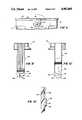
- FIG. 1is a side elevation of a carrier assembly and thin walled flexible container in accordance with one exemplary embodiment of the invention
- FIG. 2is a perspective view of the lower carrier portion of the assembly shown in FIG. 1;
- FIG. 3is a perspective view of the upper carrier portion of the assembly shown in FIG. 1;
- FIG. 4is a partial plan view of the upper carrier portion shown in FIG. 3;
- FIG. 5is a partial detail showing the upper carrier portion attached to the lower carrier portion in one position permitting pivotal movement of one relative to the other;
- FIG. 6is a partial detail showing the upper carrier portion attached to the lower carrier portion in a second position where pivotal movement therebetween is prevented;
- FIG. 7is a partial side elevation of a carrier assembly in accordance with another exemplary embodiment of the invention.
- FIG. 8is a partial plan view of the upper carrier portion shown in FIG. 7;
- FIG. 9is a partial side elevation illustrating the pivotal movement of the upper carrier portion relative to the lower carrier portion
- FIG. 10is a cross-sectional detail illustrating the manner in which the upper carrier portion may be releasably secured in one position of movement of the upper carrier portion;
- FIG. 11is a one side view of the upper carrier portion shown in FIG. 7;
- FIG. 12is the other side view of the upper carrier portion shown in FIG. 7.
- the container carrier assembly 10 of this inventionincludes a lower carrier portion 12 and an upper carrier portion 14, specifically adapted to hold a thin walled flexible and collapsible container 15.
- the lower carrier portion 12includes a generally cylindrical bucket-like member having a substantially cylindrical peripheral side wall 16, a bottom wall 18, and an upper annular peripheral edge 20.
- relatively large and generally rectangularly shaped cut-outs 22, 24, 26 and 28are provided substantially symmetrically in the peripheral side wall 16. This arrangement leaves two relatively large solid areas 30 and 32 and two relatively narrow solid areas 34 and 36 of the peripheral wall 16.
- the upper open end of the lower carrier portion 12is provided with an outwardly flared surface 38 terminating at the edge 20.
- the upper end of the lower carrier portionis also provided with a pair of outwardly projecting ears 40, 42 located diametrically opposed to each other about the circumference of the peripheral side wall 16.
- the outwardly molded projections or earsserve to create a pair of U-shaped recesses 44, 46, respectively, which open toward the interior of the lower carrier portion 12.
- Each of these recessed areas 44, 46is generally U-shaped and terminates at the upper peripheral edge 20.
- Projections 48, 50project horizontally outwardly or away from the ears 44, 46, respectively.
- the projections 48, 50each include elongated stem portions 52, joined at one end to the ears 40 and 42, and at the other end to an enlarged head portion 54. It will be appreciated that the projections 48, 50, comprise bails for detachably securing the upper carrier portion to the lower carrier portion as will be described further hereinbelow.
- the lower closed end of the lower carrier portion 12includes an annular rim 58 depending from the bottom wall lB to provide a rigid bottom support for the carrier.
- the upper carrier portion 14includes a pair of elongated flexible strap portions 62, 64 which extend from opposite sides of a container neck engaging portion 66. Lower free ends 68, 70 of the strap portions 62, 64, respectively, are provided with apertures 72, 74 which are adapted to be received over the projections 48, 50 respectively.
- Each aperture 72, 74includes an elongated slot portion 76 and an enlarged, circular head portion 78. As shown in FIGS. 5 and 6, in a first orientation (FIG. 5), the elongated slot portion 76 is located below the enlarged head portion 78 so that the strap portions 62, 64 may be fitted over the enlarged head portions 78. As best seen in FIG.
- the strap portion 62has a handle 80 integrally formed therewith.
- the upper end 82 of the handleis joined to the container neck engaging portion 66 immediately above the merger of the strap portion 62 with the neck engaging portion 66.
- the lower end 84 of the handleincludes a reverse curve 86 which merges into the strap portion 62.
- the intermediate or gripping portion 88 of the handle 80is spaced away from the strap portion 62 to thereby form a closed loop which defines a handle opening 90.
- the gripping portion 88is formed by a relatively smooth surface 92 and a plurality of ribs or vanes 94 which extend substantially perpendicularly away from the surface 92. It will be appreciated that the handle 80 may have various other surface configurations which are nevertheless to be considered within the scope of this invention.
- the other strap portion 64is generally channel shaped, including a pair of upstanding side walls 96 extending along either side of the strap portion 64, and terminating at the lower end, above the aperture 74. These side wall surfaces terminate at the upper end of the strap portion 64 where they join with the container neck engaging portion 66.
- the container neck engaging portion 66is of generally inverted U-shape, depending on the direction of observation.
- the container neck engaging portionwill be considered to have a substantially inverted U-shape in plan, as viewed in FIG. 4. It is important to note that the neck engaging portion 66 opens in a direction substantially perpendicular to the axis A. This arrangement permits the upper carrier portion 14 to be rotated about the axis A into and out of a container neck engaging position as described below.
- the neck engaging portion 66is formed with a tapered collar portion 98 which joins to a substantially vertical wall 100.
- the interior surface of the wall 100is provided with three vertically spaced, horizontal ribs 102, 104 and 106.
- the upper and lower ribs 102, 106have substantially identical shapes, corresponding substantially to the curvature of the vertical wall 100.
- the intermediate rib 104has a first arcuate portion 108 which has an arcuate surface, the radius of curvature of which substantially corresponds to the adjacent radius of curvature of the container neck.
- At opposite ends of the arcuate portion 108are flared portions 110, 112 with bevelled entry portions 114, 116, respectively, which serve as guide edges during pivotal movement of the upper carrier portion 14 into the container neck engaging position.
- the rib 104extends radially inwardly a greater extent than either of the upper and lower ribs 102, 106. This arrangement permits the series of ribs 102, 104, 106 to generally conform to the container neck as best seen in FIG. 1.
- the arcuate portion 108extends circumferentially greater than 270° so that, upon engagement with a container neck of similar diameter, the upper carrier portion 14 may be snapped into place about the container neck.
- the container 15may be substantially as shown and described in my above identified parent application Ser. No. 07/432,672 with slight variations in shape as described below.
- the container 15includes a peripheral side wall 118, a bottom wall 120 and a tapered or domed shoulder 122 terminating at an upstanding neck or dispensing portion 124.
- the containermay include a textured reinforcing area 126 extending about the periphery of the container where the side wall 118 merges with the shoulder 122.
- the neck 124includes a pronounced radially outwardly directed flange 126 (which may be solid or hollow). From FIG. 1, it may be appreciated that the ribs 102, 104 and 106 engage the neck 124 below the flange 126, with the upper rib 106 providing some support for the container 15 as a whole by engaging the underside of the flange 126.
- neck portion 124terminates at a closure receiving area 128 which may include exterior threads for receiving a conventional screw-on type closure (not shown).
- the upper carrier portion 14when the upper carrier portion 14 is attached to the lower carrier portion 12 with head portions 54 of projections 48, 50 in the enlarged portions 78 of apertures 72, 74, the upper carrier portion may be pivoted about axis A to a container loading/unloading position. Upon insertion of a filled container 15 into the lower carrier portion 12, the upper carrier portion may then be pivoted to a container engaging position, with the container neck engaging portion 66 in full engagement with the container neck 124 as shown in FIG. 1.
- the upper carrier portion 14may then be pulled or flexed upwardly, sufficiently to engage stems 52 of projections 48, 50 in the slot portions 76 of apertures 72, 74 to thereby temporarily lock the upper carrier portion into place, precluding any pivotal movement of the upper carrier portion relative to the lower carrier portion.
- FIGS. 7-12a second exemplary and preferred embodiment of the subject invention is illustrated. Elements in common with the first described embodiment, are referred to in FIGS. 7-12 of the drawings with the same numerals but with a prime designation attached.
- the container carrier 130includes a lower carrier portion 12' which is substantially identical to the lower carrier portion 12 of the embodiment illustrated in FIGS. 1-6 with certain exceptions noted below.
- the lower carrier 12'includes a peripheral side wall 16', an upper peripheral edge 20' and an outwardly flared surface 38' terminating at the edge 20'.
- the lower carrier portion 12'is also provided with a pair of outwardly projecting ears 40', 42' located diametrically opposed to each other about the circumference of the peripheral side wall 16'. These outwardly molded projections or ears serve to create a pair of U-shaped recesses similar to those shown at 44, 46 in the embodiment illustrated in FIGS. 1-6.
- a pair of pivot pins 132, 134project horizontally outwardly or away from the ears 40', 42', respectively.
- the pivot pins 132, 134each include a round stem portion 136 and an enlarged head 138.
- the projecting ears 40', 42'are also formed with a pair of detents or depressions 140 which, as shown in FIG. 9, are located at the 12 o'clock and 3 o'clock positions.
- the projections 132, 134 and the detents or depressions 140are intended for use in the attachment of the upper carrier portion 14' as will be described further hereinbelow.
- the upper container carrier portion 14'includes a pair of elongated flexible strap portions 142, 144 which extend from opposite sides of the container neck engaging portion 146.
- Lower free ends 148, 150 of the strap portions 142, 144, respectively,are provided with slots 150, 152 which are adapted to be slidably engaged behind the head portions 138 of the pivot buttons 132, 134, respectively.
- Each slot 150, 152includes an entry portion 154 opening to one side of the respective strap, and an arcuate inner portion 156, into which the round stem portions 136 of pins 132, 134 may be snapped in a snug friction fit.
- the upper carrier portion 130may be pivoted to a second container loading/unloading position wherein the container neck engaging portion 146 has been rotated away from the container 15 (not shown in FIGS. 7-12) to facilitate loading and unloading of the latter.
- the bumps or projections 158will disengage from the depression 140 at the 12 o'clock position and will engage a similar depression 140 at the 3 o'clock position to thereby hold the upper carrier portion in the container loading/unloading position.
- the strap 142also comprises an integral handle.
- the strap portion 142is curved away from the container 15 at its lower portion, as indicated at numeral 160 in FIG. 7.
- the remainder of the strap 142is otherwise similar in construction to the handle portion 92 of the strap 62 illustrated in the embodiment of FIGS. 1-6, including the utilization of vertical ribs 94'.
- the other strap portion 144is similar to the strap portion 64 of the first described embodiment, again with the exception of the use of slots 150, 152, and projections 158 rather than apertures 72, 74.
- the container neck engaging portion 146 of the second exemplary embodimentis substantially identical in construction to the container neck engaging portion 66 of the embodiment illustrated in FIGS. 1-6.
- the principal differencelies in the reorientation of the container neck engaging portion 146 to face in the opposite direction from that of the embodiment illustrated in FIGS. 1-6.
- the constructionis otherwise identical and need not be described in further detail.
- the second exemplary embodimentdiffers from the first embodiment only in the manner of attachment of the upper carrier portion 14' to the lower carrier portion 12'.
- the upper carrier portion 14'may be pivoted between the container loading/unloading position and the container neck engaging position as in the first described embodiment.
- projections 158 and detents 140which releasably retain the upper carrier portion in either of the two above described positions.
Landscapes
- Engineering & Computer Science (AREA)
- Food Science & Technology (AREA)
- Details Of Rigid Or Semi-Rigid Containers (AREA)
Abstract
Description
Claims (30)
Priority Applications (3)
| Application Number | Priority Date | Filing Date | Title |
|---|---|---|---|
| US07/530,418US4982868A (en) | 1989-11-07 | 1990-05-30 | Bail type pitcher for thin walled container |
| AU80833/91AAU8083391A (en) | 1990-05-30 | 1991-05-29 | Pitcher assemblies for thin walled containers |
| PCT/US1991/003758WO1991018810A1 (en) | 1990-05-30 | 1991-05-29 | Pitcher assemblies for thin walled containers |
Applications Claiming Priority (2)
| Application Number | Priority Date | Filing Date | Title |
|---|---|---|---|
| US07/432,672US5060816A (en) | 1988-12-22 | 1989-11-07 | Composite container and associated carrier |
| US07/530,418US4982868A (en) | 1989-11-07 | 1990-05-30 | Bail type pitcher for thin walled container |
Related Parent Applications (1)
| Application Number | Title | Priority Date | Filing Date |
|---|---|---|---|
| US07/432,672Continuation-In-PartUS5060816A (en) | 1988-12-22 | 1989-11-07 | Composite container and associated carrier |
Publications (1)
| Publication Number | Publication Date |
|---|---|
| US4982868Atrue US4982868A (en) | 1991-01-08 |
Family
ID=27029597
Family Applications (1)
| Application Number | Title | Priority Date | Filing Date |
|---|---|---|---|
| US07/530,418Expired - Fee RelatedUS4982868A (en) | 1989-11-07 | 1990-05-30 | Bail type pitcher for thin walled container |
Country Status (1)
| Country | Link |
|---|---|
| US (1) | US4982868A (en) |
Cited By (27)
| Publication number | Priority date | Publication date | Assignee | Title |
|---|---|---|---|---|
| US5078291A (en)* | 1991-03-11 | 1992-01-07 | Uni-Spray Nozzles Inc. | Reusable closure device for bottles |
| US5224614A (en)* | 1992-02-07 | 1993-07-06 | The Procter & Gamble Company | Non-handled lightweight plastic bottle with a substantially rigid grip design to facilitate pouring without loss of control |
| EP0853911A1 (en)* | 1997-01-15 | 1998-07-22 | Le Creuset S.A. | Handles |
| USD398854S (en) | 1997-06-27 | 1998-09-29 | The Procter & Gamble Company | Bottle with handle |
| USD399138S (en) | 1997-06-27 | 1998-10-06 | The Procter & Gamble Company | Bottle with handle |
| USD400105S (en) | 1997-06-27 | 1998-10-27 | The Procter & Gamble Company | Bottle with handle |
| USD406767S (en)* | 1997-06-27 | 1999-03-16 | The Procter & Gamble Company | Bottle with handle |
| USD406766S (en)* | 1997-06-27 | 1999-03-16 | The Procter & Gamble Company | Bottle with handle |
| US6085097A (en)* | 1998-02-12 | 2000-07-04 | Savery; Winsor T. | Cellular communications tracking system using a multitude of assigned call-numbers |
| USD450248S1 (en) | 2000-04-03 | 2001-11-13 | Graham Packaging Company, L.P. | Lower portion of a container |
| US6543825B1 (en)* | 2000-02-15 | 2003-04-08 | Jazbec Dragutin | Bottle holder |
| US20060124580A1 (en)* | 2004-12-15 | 2006-06-15 | Graham Packaging Company, L.P. | Container and handle assembly |
| US20070012651A1 (en)* | 2005-06-07 | 2007-01-18 | Innovative Household Products, Inc. | Bottle holder |
| US20070095785A1 (en)* | 2004-06-29 | 2007-05-03 | Yoshino Kogyosho Co., Ltd. | Synthetic resin bottle with a handle |
| US20070221607A1 (en)* | 2006-03-27 | 2007-09-27 | Graham Packaging Pet Technologies Inc. | Split-ring handle and container assembly |
| US20100022498A1 (en)* | 2001-03-12 | 2010-01-28 | Intercept Pharmaceuticals, Inc. | Steroids as agonists for fxr |
| US20100305525A1 (en)* | 2008-06-02 | 2010-12-02 | Eric Tanguay | Hand-held vomit and urinal bag holder |
| US20120279970A1 (en)* | 2011-05-06 | 2012-11-08 | Saint-Gobain Abrasifs | Paint cup assembly with an extended ring |
| US20130161470A1 (en)* | 2010-06-02 | 2013-06-27 | Brasilata S.A. Embalagens Metalicas | Suspension Device for Containers |
| US9162240B2 (en) | 2004-12-16 | 2015-10-20 | Saint-Gobain Abrasives, Inc./Saint-Gobain Abrasie | Liquid container system for a spray gun |
| US20160318693A1 (en)* | 2015-04-30 | 2016-11-03 | Steel Technology, Llc | Insulated cap |
| US9586220B2 (en) | 2011-06-30 | 2017-03-07 | Saint-Gobain Abrasives, Inc. | Paint cup assembly |
| US10035156B2 (en) | 2006-06-20 | 2018-07-31 | Saint-Gobain Abrasives, Inc. | Liquid supply assembly |
| US10882064B2 (en) | 2011-12-30 | 2021-01-05 | Saint-Gobain Abrasives, Inc./Saint-Gobain Abrasifs | Convertible paint cup assembly with air inlet valve |
| EP3824774A1 (en)* | 2019-11-22 | 2021-05-26 | BSH Hausgeräte GmbH | Water tank lid |
| US11040360B2 (en) | 2006-06-20 | 2021-06-22 | Saint-Gobain Abrasives, Inc. | Liquid supply assembly |
| USD927186S1 (en) | 2018-02-05 | 2021-08-10 | Dwk Life Sciences Gmbh | Manual handling device for glass laboratory bottles |
Citations (35)
| Publication number | Priority date | Publication date | Assignee | Title |
|---|---|---|---|---|
| US535550A (en)* | 1895-03-12 | Peters co | ||
| US547713A (en)* | 1895-10-08 | William iiovexdon courtenay | ||
| US704972A (en)* | 1901-07-05 | 1902-07-15 | Frederick T Griffith | Temperature-preserving bottle-cover. |
| US770528A (en)* | 1904-09-20 | Bottle-protector | ||
| US965629A (en)* | 1909-07-02 | 1910-07-26 | Holz Mfg Company | Bottle-handling device. |
| US1468808A (en)* | 1923-09-25 | Protector | ||
| US1702555A (en)* | 1927-08-31 | 1929-02-19 | Henry P Watson | Receptacle carrier |
| US1843325A (en)* | 1931-03-03 | 1932-02-02 | Kappelly Joseph | Bottle cover |
| US2088387A (en)* | 1936-04-27 | 1937-07-27 | Jr Hudson Doniphan Rice | Bottle holder |
| US2463651A (en)* | 1947-05-06 | 1949-03-08 | Harry E Stevens | Bottle carrier |
| US2838226A (en)* | 1953-07-13 | 1958-06-10 | Keyes Fibre Co | Casing for individual bottles and objects of like shape |
| US2859891A (en)* | 1957-02-08 | 1958-11-11 | Gordon V Carkin | Nursing bottle |
| US2867364A (en)* | 1957-03-22 | 1959-01-06 | Bramante Nunzio | Holder for milk container |
| US2928570A (en)* | 1958-06-16 | 1960-03-15 | Leonard W Fitch | Gripper with plastic housing for liquid containing cartons |
| US3061129A (en)* | 1957-02-25 | 1962-10-30 | Fitzgerald Arthur Grover | Baby nursers |
| US3092277A (en)* | 1960-10-07 | 1963-06-04 | Jefferson K Brim | Thermal jacket for beverage container |
| US3202309A (en)* | 1964-03-23 | 1965-08-24 | Walter M Simpson | Carrying device |
| US3255932A (en)* | 1964-08-11 | 1966-06-14 | Union Carbide Corp | Package for flowable materials |
| US3402843A (en)* | 1966-07-11 | 1968-09-24 | Phillips Petroleum Co | Bottles with protective cape or cover |
| US3606962A (en)* | 1969-09-05 | 1971-09-21 | Scholle Container Corp | Dispensing and sealing receptacle |
| US3610671A (en)* | 1969-08-21 | 1971-10-05 | Alfred P Conger | Unitary container holder |
| US3688936A (en)* | 1971-04-26 | 1972-09-05 | Corning Glass Works | Pouring vessel |
| US3756451A (en)* | 1972-06-19 | 1973-09-04 | Popeil Brothers | Mop bucket |
| US4300612A (en)* | 1979-11-05 | 1981-11-17 | Hoffmann-La Roche Inc. | Safety enclosure for glass bottles containing hazardous materials |
| US4379578A (en)* | 1980-03-03 | 1983-04-12 | Heriberto Schuler | Reusable bottle holder |
| US4486043A (en)* | 1984-01-20 | 1984-12-04 | Rais John M | Reusable plastic bottle handle |
| US4511167A (en)* | 1983-03-25 | 1985-04-16 | Taiyo Sanso Kabushiki Kaisha | Detachable holder for containers |
| US4552396A (en)* | 1984-10-29 | 1985-11-12 | Rais John M | Bottle handle for plastic prong bottle |
| US4653671A (en)* | 1984-01-09 | 1987-03-31 | Christene Duffy | Container |
| US4660876A (en)* | 1986-01-15 | 1987-04-28 | Beverage Mate Corp. | Reusable bottle handle |
| US4666197A (en)* | 1986-04-16 | 1987-05-19 | Watson Wayne R | Bottle holder |
| US4667359A (en)* | 1985-01-15 | 1987-05-26 | Enzo Polotti | Universal grip device particularly for generic bottles and the like container |
| US4671427A (en)* | 1986-04-14 | 1987-06-09 | Farquharson Charles R | Milk bag pitcher |
| USD292160S (en) | 1985-02-04 | 1987-10-06 | Thomas Michael J | Soft drink bottle holder |
| US4896913A (en)* | 1988-09-19 | 1990-01-30 | Kennedy Steve J | Releasable self locking handle for wide body, narrow neck containers |
- 1990
- 1990-05-30USUS07/530,418patent/US4982868A/ennot_activeExpired - Fee Related
Patent Citations (35)
| Publication number | Priority date | Publication date | Assignee | Title |
|---|---|---|---|---|
| US535550A (en)* | 1895-03-12 | Peters co | ||
| US547713A (en)* | 1895-10-08 | William iiovexdon courtenay | ||
| US770528A (en)* | 1904-09-20 | Bottle-protector | ||
| US1468808A (en)* | 1923-09-25 | Protector | ||
| US704972A (en)* | 1901-07-05 | 1902-07-15 | Frederick T Griffith | Temperature-preserving bottle-cover. |
| US965629A (en)* | 1909-07-02 | 1910-07-26 | Holz Mfg Company | Bottle-handling device. |
| US1702555A (en)* | 1927-08-31 | 1929-02-19 | Henry P Watson | Receptacle carrier |
| US1843325A (en)* | 1931-03-03 | 1932-02-02 | Kappelly Joseph | Bottle cover |
| US2088387A (en)* | 1936-04-27 | 1937-07-27 | Jr Hudson Doniphan Rice | Bottle holder |
| US2463651A (en)* | 1947-05-06 | 1949-03-08 | Harry E Stevens | Bottle carrier |
| US2838226A (en)* | 1953-07-13 | 1958-06-10 | Keyes Fibre Co | Casing for individual bottles and objects of like shape |
| US2859891A (en)* | 1957-02-08 | 1958-11-11 | Gordon V Carkin | Nursing bottle |
| US3061129A (en)* | 1957-02-25 | 1962-10-30 | Fitzgerald Arthur Grover | Baby nursers |
| US2867364A (en)* | 1957-03-22 | 1959-01-06 | Bramante Nunzio | Holder for milk container |
| US2928570A (en)* | 1958-06-16 | 1960-03-15 | Leonard W Fitch | Gripper with plastic housing for liquid containing cartons |
| US3092277A (en)* | 1960-10-07 | 1963-06-04 | Jefferson K Brim | Thermal jacket for beverage container |
| US3202309A (en)* | 1964-03-23 | 1965-08-24 | Walter M Simpson | Carrying device |
| US3255932A (en)* | 1964-08-11 | 1966-06-14 | Union Carbide Corp | Package for flowable materials |
| US3402843A (en)* | 1966-07-11 | 1968-09-24 | Phillips Petroleum Co | Bottles with protective cape or cover |
| US3610671A (en)* | 1969-08-21 | 1971-10-05 | Alfred P Conger | Unitary container holder |
| US3606962A (en)* | 1969-09-05 | 1971-09-21 | Scholle Container Corp | Dispensing and sealing receptacle |
| US3688936A (en)* | 1971-04-26 | 1972-09-05 | Corning Glass Works | Pouring vessel |
| US3756451A (en)* | 1972-06-19 | 1973-09-04 | Popeil Brothers | Mop bucket |
| US4300612A (en)* | 1979-11-05 | 1981-11-17 | Hoffmann-La Roche Inc. | Safety enclosure for glass bottles containing hazardous materials |
| US4379578A (en)* | 1980-03-03 | 1983-04-12 | Heriberto Schuler | Reusable bottle holder |
| US4511167A (en)* | 1983-03-25 | 1985-04-16 | Taiyo Sanso Kabushiki Kaisha | Detachable holder for containers |
| US4653671A (en)* | 1984-01-09 | 1987-03-31 | Christene Duffy | Container |
| US4486043A (en)* | 1984-01-20 | 1984-12-04 | Rais John M | Reusable plastic bottle handle |
| US4552396A (en)* | 1984-10-29 | 1985-11-12 | Rais John M | Bottle handle for plastic prong bottle |
| US4667359A (en)* | 1985-01-15 | 1987-05-26 | Enzo Polotti | Universal grip device particularly for generic bottles and the like container |
| USD292160S (en) | 1985-02-04 | 1987-10-06 | Thomas Michael J | Soft drink bottle holder |
| US4660876A (en)* | 1986-01-15 | 1987-04-28 | Beverage Mate Corp. | Reusable bottle handle |
| US4671427A (en)* | 1986-04-14 | 1987-06-09 | Farquharson Charles R | Milk bag pitcher |
| US4666197A (en)* | 1986-04-16 | 1987-05-19 | Watson Wayne R | Bottle holder |
| US4896913A (en)* | 1988-09-19 | 1990-01-30 | Kennedy Steve J | Releasable self locking handle for wide body, narrow neck containers |
Cited By (41)
| Publication number | Priority date | Publication date | Assignee | Title |
|---|---|---|---|---|
| US5078291A (en)* | 1991-03-11 | 1992-01-07 | Uni-Spray Nozzles Inc. | Reusable closure device for bottles |
| US5224614A (en)* | 1992-02-07 | 1993-07-06 | The Procter & Gamble Company | Non-handled lightweight plastic bottle with a substantially rigid grip design to facilitate pouring without loss of control |
| EP0853911A1 (en)* | 1997-01-15 | 1998-07-22 | Le Creuset S.A. | Handles |
| USD398854S (en) | 1997-06-27 | 1998-09-29 | The Procter & Gamble Company | Bottle with handle |
| USD399138S (en) | 1997-06-27 | 1998-10-06 | The Procter & Gamble Company | Bottle with handle |
| USD400105S (en) | 1997-06-27 | 1998-10-27 | The Procter & Gamble Company | Bottle with handle |
| USD406767S (en)* | 1997-06-27 | 1999-03-16 | The Procter & Gamble Company | Bottle with handle |
| USD406766S (en)* | 1997-06-27 | 1999-03-16 | The Procter & Gamble Company | Bottle with handle |
| US6085097A (en)* | 1998-02-12 | 2000-07-04 | Savery; Winsor T. | Cellular communications tracking system using a multitude of assigned call-numbers |
| US6543825B1 (en)* | 2000-02-15 | 2003-04-08 | Jazbec Dragutin | Bottle holder |
| USD450248S1 (en) | 2000-04-03 | 2001-11-13 | Graham Packaging Company, L.P. | Lower portion of a container |
| US20100022498A1 (en)* | 2001-03-12 | 2010-01-28 | Intercept Pharmaceuticals, Inc. | Steroids as agonists for fxr |
| US20070095785A1 (en)* | 2004-06-29 | 2007-05-03 | Yoshino Kogyosho Co., Ltd. | Synthetic resin bottle with a handle |
| US7431169B2 (en)* | 2004-06-29 | 2008-10-07 | Yoshino Kogyosho Co., Ltd. | Synthetic resin bottle with a handle |
| US7143904B2 (en) | 2004-12-15 | 2006-12-05 | Graham Packaging Company, L.P. | Container and handle assembly |
| US20060124580A1 (en)* | 2004-12-15 | 2006-06-15 | Graham Packaging Company, L.P. | Container and handle assembly |
| US9162240B2 (en) | 2004-12-16 | 2015-10-20 | Saint-Gobain Abrasives, Inc./Saint-Gobain Abrasie | Liquid container system for a spray gun |
| US20070012651A1 (en)* | 2005-06-07 | 2007-01-18 | Innovative Household Products, Inc. | Bottle holder |
| US7726499B2 (en)* | 2005-06-07 | 2010-06-01 | Innovative Household Products, Inc. | Bottle holder |
| US20070221607A1 (en)* | 2006-03-27 | 2007-09-27 | Graham Packaging Pet Technologies Inc. | Split-ring handle and container assembly |
| US10035156B2 (en) | 2006-06-20 | 2018-07-31 | Saint-Gobain Abrasives, Inc. | Liquid supply assembly |
| US11040360B2 (en) | 2006-06-20 | 2021-06-22 | Saint-Gobain Abrasives, Inc. | Liquid supply assembly |
| US11548018B1 (en) | 2006-06-20 | 2023-01-10 | Saint-Gobain Abrasives, Inc. | Liquid supply assembly |
| US12064783B2 (en) | 2006-06-20 | 2024-08-20 | Saint-Gobain Abrasives, Inc. | Liquid supply assembly |
| US11679399B2 (en) | 2006-06-20 | 2023-06-20 | Saint-Gobain Abrasives, Inc. | Liquid supply assembly |
| US9044363B2 (en)* | 2008-06-02 | 2015-06-02 | Hygie Canada Inc. | Hand-held vomit and urinal bag holder |
| AU2009253791B2 (en)* | 2008-06-02 | 2014-06-26 | Hygie Canada Inc. | Hand-held vomit bag holder |
| US20100305525A1 (en)* | 2008-06-02 | 2010-12-02 | Eric Tanguay | Hand-held vomit and urinal bag holder |
| US20130161470A1 (en)* | 2010-06-02 | 2013-06-27 | Brasilata S.A. Embalagens Metalicas | Suspension Device for Containers |
| US20120279970A1 (en)* | 2011-05-06 | 2012-11-08 | Saint-Gobain Abrasifs | Paint cup assembly with an extended ring |
| US9335198B2 (en) | 2011-05-06 | 2016-05-10 | Saint-Gobain Abrasives, Inc. | Method of using a paint cup assembly |
| US8998018B2 (en)* | 2011-05-06 | 2015-04-07 | Saint-Gobain Abrasives, Inc. | Paint cup assembly with an extended ring |
| US8944351B2 (en) | 2011-05-06 | 2015-02-03 | Saint-Gobain Abrasives, Inc. | Paint cup assembly with an outlet valve |
| US9586220B2 (en) | 2011-06-30 | 2017-03-07 | Saint-Gobain Abrasives, Inc. | Paint cup assembly |
| US10882064B2 (en) | 2011-12-30 | 2021-01-05 | Saint-Gobain Abrasives, Inc./Saint-Gobain Abrasifs | Convertible paint cup assembly with air inlet valve |
| US10017301B2 (en)* | 2015-04-30 | 2018-07-10 | Helen Of Troy Limited | Insulated cap |
| US10384837B2 (en) | 2015-04-30 | 2019-08-20 | Helen Of Troy Limited | Insulated cap |
| US10661949B2 (en) | 2015-04-30 | 2020-05-26 | Helen Of Troy Limited | Insulated cap |
| US20160318693A1 (en)* | 2015-04-30 | 2016-11-03 | Steel Technology, Llc | Insulated cap |
| USD927186S1 (en) | 2018-02-05 | 2021-08-10 | Dwk Life Sciences Gmbh | Manual handling device for glass laboratory bottles |
| EP3824774A1 (en)* | 2019-11-22 | 2021-05-26 | BSH Hausgeräte GmbH | Water tank lid |
Similar Documents
| Publication | Publication Date | Title |
|---|---|---|
| US4982868A (en) | Bail type pitcher for thin walled container | |
| US4982869A (en) | Pivoting handle type pitcher for thin walled container | |
| KR100270895B1 (en) | Container with two position handle | |
| US3730372A (en) | Plastic container | |
| US3307602A (en) | Thin walled container and closure therefor | |
| US4842158A (en) | Container handle attachment | |
| US3820692A (en) | Food shaker and blender | |
| US4821899A (en) | Dispensing closure | |
| US4357042A (en) | Bail | |
| CN107531472B (en) | Closure for a container | |
| US5499736A (en) | Reclosable, removable cap for reusable shaker dispenser bottle | |
| US5085331A (en) | Spooning closure | |
| US6964359B1 (en) | Plastic container | |
| JPH05254552A (en) | Container closure with separable seal | |
| US20110210121A1 (en) | Container system | |
| US8517228B2 (en) | Dispensing cap for a container | |
| US20220297899A1 (en) | Multi Configurable Lid for Container | |
| MX2007005794A (en) | Closure with one or more lids. | |
| CZ175697A3 (en) | Isothermic bottle | |
| HU222617B1 (en) | Condiment-cellar | |
| US4832219A (en) | Dual dispensing hinged closure | |
| JPS6042106B2 (en) | liquid container | |
| US20220024657A1 (en) | Container system including lid with improved finger accommodativeness | |
| US6364385B1 (en) | Bottle handle and carry assist device | |
| IE47025B1 (en) | Improvements in or relating to a carrier |
Legal Events
| Date | Code | Title | Description |
|---|---|---|---|
| FEPP | Fee payment procedure | Free format text:PAT HLDR NO LONGER CLAIMS SMALL ENT STAT AS INDIV INVENTOR (ORIGINAL EVENT CODE: LSM1); ENTITY STATUS OF PATENT OWNER: LARGE ENTITY | |
| FPAY | Fee payment | Year of fee payment:4 | |
| AS | Assignment | Owner name:SOUTHTRUST BANK OF ALABAMA, NATIONAL ASSOCIATION, Free format text:SECURITY INTEREST;ASSIGNORS:E S ROBBINS CORPORATION A CORP. OF ALABAMA;ROBBINS, E.S., III;REEL/FRAME:007384/0316 Effective date:19950101 | |
| REMI | Maintenance fee reminder mailed | ||
| LAPS | Lapse for failure to pay maintenance fees | ||
| FP | Lapsed due to failure to pay maintenance fee | Effective date:19990108 | |
| AS | Assignment | Owner name:UNION PLANTERS BANK, NATIONAL ASSOCIATION, ALABAMA Free format text:ASSIGNMENT OF ASSIGNORS INTEREST;ASSIGNORS:ROBBINS, E.S., III;ROBBINS, MARY L.;REEL/FRAME:012852/0225 Effective date:20020417 | |
| AS | Assignment | Owner name:UNION PLANTER BANK, NATIONAL ASSOCIATION, ALASKA Free format text:SECURITY AGREEMENT;ASSIGNORS:E.S. ROBBINS CORPORATION;CENTAUR HTP NORTHEAST FENCING SYSTEMS, INC.;ROBBINS, E.S., III;AND OTHERS;REEL/FRAME:014227/0555 Effective date:20020401 | |
| STCH | Information on status: patent discontinuation | Free format text:PATENT EXPIRED DUE TO NONPAYMENT OF MAINTENANCE FEES UNDER 37 CFR 1.362 |