US4982732A - Orthopedic rehabilitation knee brace - Google Patents
Orthopedic rehabilitation knee braceDownload PDFInfo
- Publication number
- US4982732A US4982732AUS07/475,571US47557190AUS4982732AUS 4982732 AUS4982732 AUS 4982732AUS 47557190 AUS47557190 AUS 47557190AUS 4982732 AUS4982732 AUS 4982732A
- Authority
- US
- United States
- Prior art keywords
- hinge
- stops
- knee
- strut
- thigh
- Prior art date
- Legal status (The legal status is an assumption and is not a legal conclusion. Google has not performed a legal analysis and makes no representation as to the accuracy of the status listed.)
- Expired - Fee Related
Links
Images


Classifications
- A—HUMAN NECESSITIES
- A61—MEDICAL OR VETERINARY SCIENCE; HYGIENE
- A61F—FILTERS IMPLANTABLE INTO BLOOD VESSELS; PROSTHESES; DEVICES PROVIDING PATENCY TO, OR PREVENTING COLLAPSING OF, TUBULAR STRUCTURES OF THE BODY, e.g. STENTS; ORTHOPAEDIC, NURSING OR CONTRACEPTIVE DEVICES; FOMENTATION; TREATMENT OR PROTECTION OF EYES OR EARS; BANDAGES, DRESSINGS OR ABSORBENT PADS; FIRST-AID KITS
- A61F5/00—Orthopaedic methods or devices for non-surgical treatment of bones or joints; Nursing devices ; Anti-rape devices
- A61F5/01—Orthopaedic devices, e.g. long-term immobilising or pressure directing devices for treating broken or deformed bones such as splints, casts or braces
- A61F5/0102—Orthopaedic devices, e.g. long-term immobilising or pressure directing devices for treating broken or deformed bones such as splints, casts or braces specially adapted for correcting deformities of the limbs or for supporting them; Ortheses, e.g. with articulations
- A61F5/0123—Orthopaedic devices, e.g. long-term immobilising or pressure directing devices for treating broken or deformed bones such as splints, casts or braces specially adapted for correcting deformities of the limbs or for supporting them; Ortheses, e.g. with articulations for the knees
- A61F5/0125—Orthopaedic devices, e.g. long-term immobilising or pressure directing devices for treating broken or deformed bones such as splints, casts or braces specially adapted for correcting deformities of the limbs or for supporting them; Ortheses, e.g. with articulations for the knees the device articulating around a single pivot-point
- A—HUMAN NECESSITIES
- A61—MEDICAL OR VETERINARY SCIENCE; HYGIENE
- A61F—FILTERS IMPLANTABLE INTO BLOOD VESSELS; PROSTHESES; DEVICES PROVIDING PATENCY TO, OR PREVENTING COLLAPSING OF, TUBULAR STRUCTURES OF THE BODY, e.g. STENTS; ORTHOPAEDIC, NURSING OR CONTRACEPTIVE DEVICES; FOMENTATION; TREATMENT OR PROTECTION OF EYES OR EARS; BANDAGES, DRESSINGS OR ABSORBENT PADS; FIRST-AID KITS
- A61F5/00—Orthopaedic methods or devices for non-surgical treatment of bones or joints; Nursing devices ; Anti-rape devices
- A61F5/01—Orthopaedic devices, e.g. long-term immobilising or pressure directing devices for treating broken or deformed bones such as splints, casts or braces
- A61F5/0102—Orthopaedic devices, e.g. long-term immobilising or pressure directing devices for treating broken or deformed bones such as splints, casts or braces specially adapted for correcting deformities of the limbs or for supporting them; Ortheses, e.g. with articulations
- A61F2005/0132—Additional features of the articulation
- A61F2005/0165—Additional features of the articulation with limits of movement
- A61F2005/0167—Additional features of the articulation with limits of movement adjustable
- Y—GENERAL TAGGING OF NEW TECHNOLOGICAL DEVELOPMENTS; GENERAL TAGGING OF CROSS-SECTIONAL TECHNOLOGIES SPANNING OVER SEVERAL SECTIONS OF THE IPC; TECHNICAL SUBJECTS COVERED BY FORMER USPC CROSS-REFERENCE ART COLLECTIONS [XRACs] AND DIGESTS
- Y10—TECHNICAL SUBJECTS COVERED BY FORMER USPC
- Y10T—TECHNICAL SUBJECTS COVERED BY FORMER US CLASSIFICATION
- Y10T403/00—Joints and connections
- Y10T403/32—Articulated members
- Y10T403/32254—Lockable at fixed position
- Y10T403/32262—At selected angle
- Y10T403/32319—At selected angle including pivot stud
- Y10T403/32327—At selected angle including pivot stud including radially spaced detent or latch component
- Y10T403/32361—Engaging recess in radial face
Definitions
- This inventionrelates to therapeutic knee braces. More particularly, an improved hinge element is disclosed for use on both sides of an orthopedic rehabilitation knee brace.
- the improved hingeis characterized by labeled, easily set and easily locked flexion and extension stops for post-operative or recovery bracing of the knee with restraint of knee movement.
- Therapeutic knee bracesare commonly installed on the operating table after knee surgery or alternately after an injury to the knee. Such braces are maintained on the knee for two purposes. First, the braces have the purpose of bracing the knee during movement. Second, the braces are present to limit knee movement in flexion or extension beyond limits where reinjury to the knee may occur.
- knee bracessatisfactorily reinforce the knee during movement. It is in the limitation of knee movement that problems occur.
- bracesbe capable of being adjustable within limits required for the healing restraint of the patient's knee. Limits used are both in flexion and extension.
- Flexionis designated as flexing of the knee from the extended position to the position where the foot and ankle comes under the buttock. Extension is a term applied to the opposite movement. The extended leg is straight with virtually no bending at the knee joint.
- a therapeutic knee jointOn a post-operative or rehabilitation application, a therapeutic knee joint must be capable of being rapidly set to given limits of both flexion and extension. Such setting should preferably occur at the time of brace installation. It would be preferred if setting could occur with minimum usage of special tools or manipulation.
- knee braces once setshould be reasonably free from patient or bystander tampering. That is to say, once the hinge of such a brace is set for limits of flexion or extension, changing of the setting should only occur under deliberate alteration, either personally by the physician or therapist or at the instruction of the physician or therapist.
- bracesshould be readily adjustable responsive to sensory input from the patient.
- patientsare frequently asked to flex a knee being rehabilitated until some discomfort is noted.
- the discomfortoccurs, there is a need to set the brace to that degree of flexion or extension required for rehabilitation without further “testing" of the limits of movement of the recovering knee joint.
- Bledsoe U.S. Pat. No. 4,817,588is exemplary of prior art knee braces and includes paired hinge members limiting flexion with straps limiting extension.
- the disclosed hingehas a single adjustable dial that cooperates with a pair of stop members to selectively limit the relative pivotal movement between the thigh and calf supporting members associated with the hinge.
- Bledsoe U.S. Pat. No. 4,407,276is an example of a knee brace the purpose of which is for reinforcement of the knee joint. Limitations of movement are not provided by the hinge members.
- Martin U.S. Pat. No. 4,489,718is an example of a knee brace hinge wherein the restraints in flexion and extension are set by a threaded member, in this case a coil, to set the limits of hinge movement.
- the braceincludes two hinge members on both sides of the knee.
- Each hinge memberis an improved circular hinge element with a first set of stops for producing restraint in knee flexion and a second set of stops for producing restraint in knee extension.
- Extending upwardly and downwardly from the circular hinge housing on both sides of the brace from both hingesare respective upper and lower telescoping wings for desired restriction of the calf and thigh portions of the leg from the paired hinge members on either side of the knee joint.
- Each hinge memberincludes a circular housing with discrete stops at 10° intervals.
- the discrete stopsare positioned radially of the hinge and are normally in a radially inward disengaged position.
- Stop operating pointsextend through slots in the cover of the hinge members and are exposed to the outside surface of the knee.
- the slots and operating pointsact as indicators displaying to the party setting the hinge the respective values of flexion and extension for any individual hinge setting.
- the discrete stopsmove between an engaged and disengaged position at a detent point on the stop acting against a radial leaf spring.
- the radial leaf springis backed by a stop retaining locking ring.
- the stop retaining locking ringis moved away from the radial leaf spring, movement of the stops can occur.
- the stop retaining locking ringis pressed against the radial leaf spring, movement of the stops at their detents is inhibited and the hinge is locked in its setting.
- An object to this inventionis to disclose an improved joint for a knee brace which is simply set in both values of extension and flexion. Accordingly, 16 stops are radially aligned at 10° increments for adjustment of extension. Similarly, 16 radially aligned stops at 10° intervals are adjustable for flexion. Normally all stops--except those at the ends of limit of travel--are in the retracted radially inward position. Each stop has a protruding operating point exposed to the exterior of the hinge through an appropriate labeled slot. By the expedient of manipulating the stop at the operating point, desired values of flexion and extension are both set and indicated exteriorly of the hinge.
- stopsare easily manipulated externally of the hinge and provide indicators of hinge movement which can be quickly read. Further, the stops can be moved with any relatively pointed implement including a ballpoint pen, a safety pin, a pencil, or any other pointed object capable of fitting into the radially aligned slots and exerting a minimum force to overcome the detent mechanism.
- any relatively pointed implementincluding a ballpoint pen, a safety pin, a pencil, or any other pointed object capable of fitting into the radially aligned slots and exerting a minimum force to overcome the detent mechanism.
- the improved hinge of this braceis provided on the exterior of the body of the hinge with an indicator for both flexion and extension.
- This indicatorcan be utilized with the radially aligned and labeled stops for rapid setting of the brace. For example, the patient can be asked to carefully flex the unrestrained and recovering knee joint. The attending physician or therapist can readily observe the coincident of the hinge indicator at a labeled radial slot. The degree of limb movement needed to permit recovery with minimum discomfort and maximum therapeutic effect can be rapidly set on the hinge.
- a further object to this inventionis to disclose numerous stops which can be readily and individually manipulated during adjustment but which can be easily locked during normal knee brace operation.
- each of the stopsis equipped with a detent.
- the detentis backed by a spring leaf from a radial leaf spring assembly.
- the radial leaf springis in turn backed by a stop retaining locking ring. This stop retaining locking ring moves between a position where all stops are restrained from motion by their detent to a position where all stops can be toggled between a hinge restraining position and a normally open position.
- An advantage of this aspect of the inventionis that movement of the hinge from the adjustable format to the locked format is simply accomplished by tightening of the stop retaining locking ring against the radial leaf spring.
- the hingewhen set to the desired limits of motion, enables convenient locking of all of the individually adjustable stops.
- the further advantage of this inventionis that the tightening of the stop retaining locking ring can be restricted to an especially constructed tool.
- a compliance lockinhibits patient or bystander tampering with the adjusted hinge It will be understood that it is not the purpose of this invention to render the hinge settings tamper proof. It is the purpose of this invention to make such tampering inconvenient so that only deliberate action can change hinge adjustment.
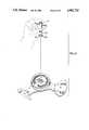
- FIG. 1is a perspective of the knee brace of this invention shown in a disposition for clamping a knee, with only portions of the braced thigh and calf being illustrated in broken lines;
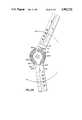
- FIG. 2is an exploded version of one-half of the knee brace, this exploded version disclosing the hinge and wings but only illustrating one stop;
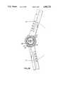
- FIG. 3is an exploded view of the operative portion of one of the hinge elements for the stop
- FIG. 4illustrates a specialized tool used for locking and unlocking the brace
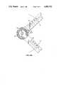
- FIG. 5Aillustrates a single hinge, the hinge here shown with the cover plate on and manipulated for limiting knee movement to 30° of extension;
- FIG. 5Bshows the hinge element of FIG. 5A with the cover removed, this hinge element shown with a stop limiting hinge motion to 30° of extension;
- FIG. 6Aillustrates the hinge member of FIG. 5A with the knee joint flexed to and limited to 90° of flexion;
- FIG. 6Billustrates the hinge member of FIG. 5B with the cover plate removed and the hinge member limited to 90° of flexion.
- a knee brace Bis shown in perspective bracing a calf C and a thigh T at the knee joint (the knee not being shown).
- two hinge elements H 1 and H 2operate to effect the desired bracing of the knee. These respective hinge elements perform two functions.
- the hinge elements H 1 , H 2 , along their respective axis 14enable the knee to be therapeutically reinforced as the knee bends.
- bending with the weight of the body between the thigh T and the calf Coccurs with part of the stress being delivered through the respective hinge joints H 1 and H 2 .
- the hinge joints H 1 and H 2each serve to restrict the degree of movement permitted between the thigh T and the calf C at the knee joint coincident to axis 14. It is this restriction of motion that constitutes the primary purpose of this invention.
- hinge element H 2is connected to a calf strut 20 and to a thigh strut 22.
- Hinge H 1is similarly provided.
- Each thigh link 22is provided with three wings. As illustrated from hinge member H 1 these wings include wing P 1 , wing P 2 and wing P 3 .
- the wings P 1 and P 2 on one hand and pad P 1 on the other handtelescope with respect one to another. This telescoping enables the brace of this invention to accommodate long legs as when the wings are extended relative to one another and shorter legs as where the wings are compressed to underlie one another.
- These wingscan also be moved in total to accommodate long or short legs, by sliding along calf strut 20 and thigh strut 22.
- calf strut 20has three wings P 4 , P 5 , P 6 , telescoping with respect thereto. These strut wings telescope to and from an overlying disposition to accommodate calves of various sizes.
- Each of the respective wing members P 1 , P 2 and P 3are of an arcuate profile, semi-rigid and encircled by straps. Specifically, straps S 1 and S 2 encircle wing members P 1 and P 2 As indicated, straps S 1 , S 2 are threaded through wing P 1 at the side edges of wing P 1 . Straps S 1 and S 2 pass around wing member P 2 . Such threading assures firm bias of the wings P 1 and P 2 to the thigh. Similarly, a strap S 3 secures wing P 3 . It will be appreciated that should wing P 6 be telescoped underlying wing P 2 strap S 3 , may be removed.
- wing P 4is provided with strap S 4 and S 5 . These straps thread through wing P 4 and extend around the side edges of P 5 to firmly grip the calf.
- a strap S 6is here shown in broken lines. For large calves and assuming that wing P 6 telescopes outwardly from under wing P 5 , strap S 6 may add to the bracing.
- buckles 30may be utilized at the ends of the wings, these buckles permitting tightening of the straps and releasable attachment of the straps and brace. As such buckles are well known in the prior art, they will not be further set forth herein.
- FIG. 2and exploded version of a hinge H is illustrated together with the telescoping wings. It will be realized that this assembly is duplicated on both sides of the leg. Telescoping wings will first be described. Thereafter, the exploded components of the hinge will be set forth.
- thigh strut 22is provided with an elongate slot 23. It is into this slot 23 at a backing bar 24 covered by a velcro strip 27 there is secured wings P 3 , P 1 , and P 2 .
- wings P 3through respective elongate slots 33, 34 moves on respective threaded screws 35, 36 in telescoping relation along slot 23.
- the threaded screws 35, 36enable wings P 1 and P 2 at apertures 37, 38 to move along the length of the slot 23 in thigh strut 22.
- fastening of the respective wings P 2 and P 3occurs at hand nuts 39. It will therefore be understood that the range of movement of the respective wings P 1 and P 3 accommodates long and short respective lengths with respect to the exploded hinge member H illustrated in FIG. 2.
- bar 20includes a bend 47 which bend 47 enables the pad P 4 , P 5 , P 6 to grasp the relatively smaller calf C with respect to the thigh T.
- Calf strut 20has a cam portion 40 of the hinge fitted thereto.
- Cam portion 40is circular and fits at pins 40A into holes 40B in calf strut 20.
- Cam member 40forms a portion of the hinge against which stops 60 act.
- the stops 60act against an annular cam defined interior of the hinge member 40. This annular cam will be further set forth with respect to FIGS. 3, 5B, and 6B.
- Calf strut 20includes a circular aperture 28. It is through this circular aperture 28 that circular hinge member 42 at pins 42A keys to apertures 42B and thigh strut 22. As will hereinafter be explained in more detail, stops 60 key to slots in circular hinge member 42.
- stop 60includes two active portions. There is a detent portion 62. As will hereinafter be set forth, this detent acting against individual spring leafs of an overlying circular leaf spring 50 enables the stop 60 to toggle. The stop 60 toggles between an inwardly disposed radially disengaged position and an outwardly disposed engaging position. Second, the stop 60 includes an operating portion 63. Operating portion 63 forms two functions.
- the operating portionpermits manipulation of the stop 60 from the exterior of the hinge.
- the operating portion 63acts as an indicator. This indicator displays when the stop is in the engaged position or disengaged position.
- a radial leaf spring assemblyOverlying the respective stops is a radial leaf spring assembly having individual leafs for each stop 50. Radial spring 50 bears against the stop 60 at detent 62. This enables toggling of the stop to and from the radially engaging position acting on spring 60.
- Stop retaining ring 52prevents flexing of spring 50 when the ring is engaged firmly over the spring.
- the respective stops 60may be toggled between their respective engaged and disengaged position.
- Hinge member 44serves three discrete functions.
- hinge member 44captures the stops 60 within the hinge member. It prevents the assembled pieces from becoming disengaged from the hinge.
- hinge member 44provides apertures 44a for compressing the stop locking ring 52 towards and away from the individual stop 60.
- the hinge member 44includes a number of elongate slots. These respective elongate slots enable the operating portion 63 of the respective slots to be manipulated to move the respective stop 60 between their engaged and disengaged position. At the same time, the operating portions 63 provide indicators of the respective positions, engaged or disengaged, of the respective stops.
- bearing washer 54in combination with screw 55 and bolt 56 enables stop retaining ring 52 to be biased towards and away from the respective stops 60. Tightening of the nut 56 thus can lock or unlock all 32 stops 60 for manipulation in setting the limits of movement of the hinge.
- cam portion 40 of the hinge Hcan be understood.
- an annular cam 90having respective ends 91, 92 is configured within an otherwise ring-like hinge member. Respective ends of the cam 91, 92 are the members against which stops 60 abut. Stops 60 in their abutment limit the degrees of hinge movement through the respective struts 20, 22 (see FIGS. 1 and 2).
- a lower continuous annular surface 93enables smooth rotation of hinge members 42 and 44 relative to cam member 40.
- the top portion 44 of the hingealso includes radial slots 44B. These respective slots 44B have the operating portion 63 of stop 60 protruding therethrough. Thus, the operating portion 63 can act as an indicator of stop position as well as being directly manipulated by an instrument configured to fit within the slots 44B. Just as there are 32 stops, there are 32 slots configured in top 44. As can be seen, the pictorial representative of FIG. 3 does not include the full number of slots.
- a special tool 57is illustrated for tightening and loosening the stop locking ring 52.
- a special keyhas been utilized having two protruding tangs 58. These protruding tangs 58 fit within complimentary apertures 59' within optional nut 56A. Other keys can likewise be substituted.
- the respective hinge pieces 40, 42, 52, 44are preferably all constructed from fiber reinforced nylon or can be of other high strength materials.
- the stops 60are made of hardened steel. It has been found that with this selection of materials which is sufficiently strong for therapeutic purposes a preferred hinge is produced. It is to be understood that these materials do not impart sufficient strength to the brace to make it a so-called "activity" brace. This brace is intended for use in rehabilitation by reasonably careful patients who avoid active physical exercise of the limb.
- FIGS. 5A and 5BAttention will now be directed to FIGS. 5A and 5B for illustrating extension and FIGS. 6A and 6B for illustrating flexion.
- the hinge assemblyhas been partially assembled in accordance with the exploded view of FIGS. 2 and 3. Missing from the hinge assembly are hand nut 56 and bearing washer 54.
- stopsare present. In the view of FIG. 5A, two of these stops 60E are immovable in the engaged position so as to prevent missetting of stops beyond a position which would result in injury to the knee. Of the other 30 stops only two stops are utilized. These stops are flexion stop at the 0° position 60A in the disengaged position and flexion stop 60B at the 90° position in the engaged disposition. Likewise, two extension stops are illustrated. These stops are extension stop 60C in the disengaged position and extension stop 60D in the engaged position.
- piece 44has been removed. Removal of piece 44 exposes the respective stops acting on the cam hinge member 40. Specifically, it can be seen that stop 60D contacts annular cam surface 90 at end 92. Thus, it can be seen that the extension stop in the outward position limits further extension of the hinge and hence further extension of the brace as it is illustrated in FIG. 1.
- the hinge illustrated in 6Bis shown in the flexion position. Stop 60B in the radially extended position has limited further flexion of the respective links 22, 24. As can be seen through the top hinge member 44, stop 60B is in the radially outward engaged position.
- stop 60Bcontacts cam surface end 91 of the cam surface 90.
- the cam hinge memberincludes oppositely disposed gun sight exterior markings.
- a gun sight marking 100appears at opposite cam end 91.
- a second gun sight markingappears opposite cam end 92.
- a patient under rehabilitationcan be asked to flex his knee until physical discomfort occurs. Once the discomfort occurs, the respective gun sight 101 will be registered adjacent a labeled stop in either extension or flexion. At this point, the respective stop nearest the gun sight indicator 100 in the case of extension and 101 in the case of flexion can be moved outwardly for limiting movement of the joint of hinge H. Thus, it can be seen that the respective gun sight indicators 100, 101 cooperate with the imprinted scales to produce rapid setting of the joint.
- FIGS. 5A and 6Aillustrate a hinge cap useful for outside of the brace when placed on the left knee or the inside of the brace when placed on the right knee.
- a cap for the inside of the left knee or the outside of the right kneecan be produced.
Landscapes
- Health & Medical Sciences (AREA)
- Nursing (AREA)
- Orthopedic Medicine & Surgery (AREA)
- Engineering & Computer Science (AREA)
- Biomedical Technology (AREA)
- Heart & Thoracic Surgery (AREA)
- Vascular Medicine (AREA)
- Life Sciences & Earth Sciences (AREA)
- Animal Behavior & Ethology (AREA)
- General Health & Medical Sciences (AREA)
- Public Health (AREA)
- Veterinary Medicine (AREA)
- Orthopedics, Nursing, And Contraception (AREA)
Abstract
Description
Claims (18)
Priority Applications (1)
| Application Number | Priority Date | Filing Date | Title |
|---|---|---|---|
| US07/475,571US4982732A (en) | 1990-02-06 | 1990-02-06 | Orthopedic rehabilitation knee brace |
Applications Claiming Priority (1)
| Application Number | Priority Date | Filing Date | Title |
|---|---|---|---|
| US07/475,571US4982732A (en) | 1990-02-06 | 1990-02-06 | Orthopedic rehabilitation knee brace |
Publications (1)
| Publication Number | Publication Date |
|---|---|
| US4982732Atrue US4982732A (en) | 1991-01-08 |
Family
ID=23888164
Family Applications (1)
| Application Number | Title | Priority Date | Filing Date |
|---|---|---|---|
| US07/475,571Expired - Fee RelatedUS4982732A (en) | 1990-02-06 | 1990-02-06 | Orthopedic rehabilitation knee brace |
Country Status (1)
| Country | Link |
|---|---|
| US (1) | US4982732A (en) |
Cited By (100)
| Publication number | Priority date | Publication date | Assignee | Title |
|---|---|---|---|---|
| WO1993002644A1 (en)* | 1991-08-05 | 1993-02-18 | Ultraflex Systems, Inc. | Dynamic splint |
| US5188584A (en)* | 1989-03-24 | 1993-02-23 | Petrofsky Research, Inc. | Orthosis for assistance in walking |
| US5292303A (en)* | 1992-07-01 | 1994-03-08 | Smith & Nephew Donjoy, Inc. | Hinged orthopedic brace having an adjustable pivot range |
| US5358468A (en)* | 1993-03-26 | 1994-10-25 | Matthew C. Longo | Adjustable resistance knee rehabilitating and strengthening apparatus |
| US5372574A (en)* | 1991-11-14 | 1994-12-13 | Hino; Takumi | Artificial limb joint and joint device |
| US5409449A (en)* | 1993-07-09 | 1995-04-25 | Smith & Nephew Donjoy Inc. | Detent mechanism for a hinged orthopedic brace |
| US5437611A (en)* | 1993-12-01 | 1995-08-01 | Orthotic Rehabilitation Products, Inc. | Dynamic brace joint |
| US5472410A (en)* | 1994-04-22 | 1995-12-05 | Deroyal/Lmb, Inc. | Adjustable flexion and extension joint orthoses |
| FR2733905A1 (en)* | 1995-05-12 | 1996-11-15 | Berrehail Mohammed | Hinged brace for knee |
| US5658241A (en)* | 1990-02-09 | 1997-08-19 | Ultraflex Systems, Inc. | Multi-functional dynamic splint |
| US5672152A (en)* | 1995-11-28 | 1997-09-30 | Breg, Inc. | Hinge for an orthopedic brace having an adjustable range of rotation |
| FR2747917A1 (en)* | 1996-04-25 | 1997-10-31 | Defrance Jean Marie | Leg splint e.g. for rehabilitation of knee joint after surgery |
| EP0832624A2 (en) | 1996-09-25 | 1998-04-01 | Johnson & Johnson Medical Limited | Hinge with movement limitation |
| US5749840A (en)* | 1989-12-07 | 1998-05-12 | Ultraflex Systems, Inc. | Dynamic splint |
| US5817040A (en)* | 1995-08-24 | 1998-10-06 | Restorative Care Of America Incorporated | Knee and elbow orthosis |
| US5827208A (en)* | 1995-11-28 | 1998-10-27 | Breg, Inc, | Hinge for an orthopedic brace having a selectively positionable stop to limit rotation |
| US5860943A (en)* | 1998-04-06 | 1999-01-19 | Restorative Care Of America Incorporated | Abductor hinge for a hip stabilizer and method of adjusting the same |
| US5873847A (en)* | 1996-11-14 | 1999-02-23 | Lenjoy Engineering, Inc. | Articulated splints and goniometric hinge for the same |
| US5891061A (en)* | 1997-02-20 | 1999-04-06 | Jace Systems, Inc. | Brace for applying a dynamic force to a jointed limb |
| US5891068A (en)* | 1997-03-28 | 1999-04-06 | Kenney; John P. | Orthotic device for treating contractures due to immobility |
| US5921946A (en)* | 1997-10-22 | 1999-07-13 | Smith & Nephew, Inc. | Joint brace hinges |
| US5997493A (en)* | 1996-09-25 | 1999-12-07 | Johnson & Johnsonprofessional, Inc. | "Hinge with movement limitation" |
| US6064912A (en)* | 1997-03-28 | 2000-05-16 | Kenney; John P. | Orthotic/electrotherapy for treating contractures due to immobility |
| US6161982A (en)* | 1998-04-22 | 2000-12-19 | Splined Tools Corporation | Assembly with a sealed coupler |
| US6206846B1 (en)* | 1997-03-28 | 2001-03-27 | John P. Kenney | Orthotic device for treating contractures due to immobility |
| EP1086672A2 (en) | 1999-09-25 | 2001-03-28 | Depuy Orthopaedics, Inc. | Orthopaedic brace having a range of motion hinge with radially actuated stops |
| EP1086671A2 (en) | 1999-09-27 | 2001-03-28 | Depuy Orthopaedics, Inc. | Orthopaedic brace having a range of motion hinge with an adjustable-length strut |
| US6383156B1 (en) | 1999-09-27 | 2002-05-07 | Dj Orthopedics, Llc | Orthopaedic brace having a range of motion hinge with an adjustable-length strut |
| DE10057462A1 (en)* | 2000-11-20 | 2002-05-23 | Lohmann & Rauscher Gmbh & Co | Orthosis, in particular to be used after knee operation, comprising adjustable fastening elements |
| US6589195B1 (en) | 2000-05-26 | 2003-07-08 | Orthomerica Products, Inc. | Modular adjustable prophylactic hip orthosis and adduction/abduction joint |
| US20040049140A1 (en)* | 2002-09-11 | 2004-03-11 | Doty Alexis E. | Lockable Hinge |
| JP2004515312A (en)* | 2000-12-12 | 2004-05-27 | ディージェイ オーソペディクス,リミテッド ライアビリティー カンパニー | Orthopedic brace with adjustable length support |
| US6840141B2 (en) | 2003-01-09 | 2005-01-11 | Brian T. Cole | Radial indexing head tool with floating splined pin |
| US20050070831A1 (en)* | 2003-09-29 | 2005-03-31 | Royce Medical Company | Adjustable ergonomic knee brace |
| WO2005039459A1 (en)* | 2003-10-22 | 2005-05-06 | Izumi Gishi Sougu Seisakusho Co., Ltd. | Articulated joint for prosthetic brace |
| US6893411B1 (en)* | 2003-03-21 | 2005-05-17 | Deroyal Industries, Inc. | Thigh cuff extension |
| EP1563812A1 (en) | 1999-09-27 | 2005-08-17 | DJ Orthopedics, LLC | Orthopaedic brace having a range of motion hinge with an adjustable-length strut |
| US20050178249A1 (en)* | 2003-01-09 | 2005-08-18 | Cole Charles A. | Radial indexing head tool with floating splined pin |
| US20050187505A1 (en)* | 2004-02-24 | 2005-08-25 | Tamarack Habilitation Technologies, Inc. | Spherical joint orthosis |
| US20050209541A1 (en)* | 2004-03-17 | 2005-09-22 | Kenney John P | Orthotic device |
| US20050240135A1 (en)* | 2004-04-21 | 2005-10-27 | Carl Hoffmeier | Osteoarthritis brace |
| US6993808B1 (en)* | 2000-09-18 | 2006-02-07 | Lenjoy Medical Engineering, Inc. | Adjustable hinges for orthopedic splints |
| US7011641B1 (en)* | 2003-10-29 | 2006-03-14 | Anatomical Concepts, Inc. | Knee brace immobilizer |
| US20060074362A1 (en)* | 2002-03-03 | 2006-04-06 | Benny Rousso | Portable device for the enhancement of circulation of blood and lymph flow in a limb |
| US20060155232A1 (en)* | 2005-01-12 | 2006-07-13 | Ceriani Dylann D | Method for fitting an orthopedic brace to the body |
| US20060155230A1 (en)* | 2005-01-12 | 2006-07-13 | Mason Jeffrey T | Releasably locking hinge for an orthopedic brace having adjustable rotation limits |
| US20060155229A1 (en)* | 2005-01-12 | 2006-07-13 | Ceriani Dylann D | Support assembly for an orthopedic brace having a length-adjusting mechanism |
| US20060211966A1 (en)* | 2005-03-14 | 2006-09-21 | Hatton Dale L | Knee joint for orthosis |
| US20060235342A1 (en)* | 2005-04-19 | 2006-10-19 | Jeff Win | Physical rehabilitation device |
| US20060247565A1 (en)* | 2003-09-29 | 2006-11-02 | David Cormier | Adjustable ergonomic knee brace |
| US20060285915A1 (en)* | 2005-06-01 | 2006-12-21 | Norgren Automotive, Inc. | Apparatus for incrementally adjusting a modular tooling coupling |
| US20070067957A1 (en)* | 2005-09-23 | 2007-03-29 | Restorative Care Of America Incorporated | A rachet hinge for a knee or elbow orthosis |
| US20070083136A1 (en)* | 2005-10-12 | 2007-04-12 | Ossur Hf | Knee brace |
| RU2299709C2 (en)* | 2005-03-28 | 2007-05-27 | Федеральное государственное унитарное предприятие "ЦИТО" | Apparatus for correction of deformations in knee joint |
| US20070270976A1 (en)* | 2002-04-25 | 2007-11-22 | Ultraflex Systems, Inc. | Ambulating ankle & knee joints with bidirectional dampening and assistance using elastomeric restraint |
| WO2007067929A3 (en)* | 2005-12-06 | 2007-11-29 | Randall Fischer | Adjustable shoulder orthotic |
| US20080139985A1 (en)* | 2004-03-10 | 2008-06-12 | Robert Gilmour | Patella Femoral Brace |
| US20080146980A1 (en)* | 2004-06-09 | 2008-06-19 | Benny Rousso | Portable Self-Contained Device for Enhancing Circulation |
| US20080148519A1 (en)* | 2007-01-08 | 2008-06-26 | Chih-Ching Chang | Hinge assembly |
| US20080255494A1 (en)* | 2004-06-06 | 2008-10-16 | Flowmedic Limited | Sleeves for Accommodating a Circulation Enhancement Device |
| US7513881B1 (en)* | 2005-01-12 | 2009-04-07 | Ossur Hf | Knee immobilizer |
| US20090198162A1 (en)* | 2002-04-25 | 2009-08-06 | Ultraflex Sytems, Inc. | Ambulating knee joint |
| US20100016772A1 (en)* | 2008-07-21 | 2010-01-21 | Anatomical Concepts, Inc. | Multiple function ratcheting orthotic device |
| US20100016773A1 (en)* | 2008-07-21 | 2010-01-21 | Anatomical Concepts, Inc. | Coordinated Cuff Displacement in an Orthotic Device |
| US20100019214A1 (en)* | 2008-07-21 | 2010-01-28 | Indexable Tools, LLC | Hammer and crowbar with adjustable claw |
| US20100174220A1 (en)* | 2009-01-08 | 2010-07-08 | Breg, Inc. | Orthopedic Elbow Brace Having a Length-Adjustable Support Assembly |
| US20100256543A1 (en)* | 2009-03-31 | 2010-10-07 | Top Shelf, Inc | Post operative hinge brace |
| US20110314637A1 (en)* | 2010-06-25 | 2011-12-29 | Djo, Llc | Hinge for an orthopedic brace |
| US8100841B2 (en) | 2003-09-03 | 2012-01-24 | Benny Rousso | Portable device for the enhancement of circulation |
| US8105252B2 (en) | 2004-09-29 | 2012-01-31 | Benny Rousso | Device for providing intermittent compression to a limb |
| US8157754B2 (en) | 2001-03-05 | 2012-04-17 | David Weintraub | Portable device for the enhancement of circulation and for the prevention of stasis related DVT |
| US8235921B2 (en) | 2005-05-01 | 2012-08-07 | Flow Medic Limited | Computerized portable device for the enhancement of circulation |
| WO2012107921A1 (en)* | 2011-02-07 | 2012-08-16 | Bioness Neuromodulation, Ltd. | Adjustable orthosis for electrical stimulation of a limb |
| US20130152337A1 (en)* | 2011-12-14 | 2013-06-20 | Euro-Pro Operating Llc | Surface cleaning apparatus with a sideways pivoting handle |
| USD693930S1 (en) | 2012-07-12 | 2013-11-19 | Ossur Hf | Pair of struts for an orthopedic device |
| US20140234016A1 (en)* | 2013-02-21 | 2014-08-21 | Tecnoway Srl | Brace for articulation |
| US8868217B2 (en) | 2011-06-27 | 2014-10-21 | Bioness Neuromodulation Ltd. | Electrode for muscle stimulation |
| US9125730B2 (en) | 2011-10-31 | 2015-09-08 | Ossur Hf | Orthopedic device for dynamically treating the knee |
| US9220624B2 (en) | 2010-09-16 | 2015-12-29 | Ossur Hf | Posterior cruciate ligament support brace |
| WO2016036963A1 (en)* | 2014-09-05 | 2016-03-10 | Ekso Bionics, Inc. | Exoskeleton device and method of impeding relative movement in the exoskeleton device |
| US9351864B2 (en) | 2013-01-25 | 2016-05-31 | Ossur Hf | Orthopedic device having a dynamic control system |
| US9539135B2 (en) | 2013-01-25 | 2017-01-10 | Ossur Hf | Orthopedic device having a dynamic control system and method for using the same |
| US9597786B2 (en) | 2013-08-22 | 2017-03-21 | Ossur Hf | Torque limiting tool and method for using the same |
| CN108095976A (en)* | 2018-02-06 | 2018-06-01 | 吉林大学 | A kind of bionic knee joint device for healing and training with passively rebound |
| US10076656B2 (en) | 2005-11-16 | 2018-09-18 | Bioness Neuromodulation Ltd. | Gait modulation system and method |
| US10076462B2 (en) | 2016-04-27 | 2018-09-18 | Radial Medical, Inc. | Adaptive compression therapy systems and methods |
| US10143581B2 (en) | 2013-06-21 | 2018-12-04 | Ossur Hf | Dynamic tension system for orthopedic device |
| US10413437B2 (en) | 2013-01-25 | 2019-09-17 | Ossur Iceland Ehf | Orthopedic device having a dynamic control system and method for using the same |
| CN110393619A (en)* | 2019-07-02 | 2019-11-01 | 广州黑格智造信息科技有限公司 | A kind of arthrodesis brace and production method |
| US10512305B2 (en) | 2014-07-11 | 2019-12-24 | Ossur Hf | Tightening system with a tension control mechanism |
| US10653546B2 (en) | 2014-10-31 | 2020-05-19 | Ossur Hf | Orthopedic device having a dynamic control system |
| CN111655217A (en)* | 2018-01-15 | 2020-09-11 | 新确有限公司 | Joint support unit and walking support device |
| GB2583452A (en)* | 2019-04-02 | 2020-11-04 | Promedics Orthopaedics Ltd | Improvements in or relating to limb support apparatuses |
| CN111920655A (en)* | 2020-09-27 | 2020-11-13 | 上海傅利叶智能科技有限公司 | Ankle joint device with adjustable initial angle of foot support |
| US11077300B2 (en) | 2016-01-11 | 2021-08-03 | Bioness Inc. | Systems and apparatus for gait modulation and methods of use |
| US11547590B2 (en) | 2017-11-27 | 2023-01-10 | Ossur Iceland Ehf | Orthopedic device having a suspension element |
| US11793660B2 (en)* | 2013-12-12 | 2023-10-24 | Yoel Schlesinger | Emergency limb fixation or restraining device |
| US11839564B1 (en) | 2019-08-08 | 2023-12-12 | Preferred Prescription, INC | Knee orthosis, adjustable |
| US11918500B1 (en) | 2020-03-31 | 2024-03-05 | Preferred Prescription, Inc. | Hinged knee brace with double upper strap arrangement |
| US12121463B1 (en) | 2020-02-13 | 2024-10-22 | Preferred Prescription, Inc. | Knee/elbow brace |
Citations (7)
| Publication number | Priority date | Publication date | Assignee | Title |
|---|---|---|---|---|
| US2770811A (en)* | 1952-04-29 | 1956-11-20 | Steeper Charles Philip | Artificial limbs |
| US4340041A (en)* | 1979-01-24 | 1982-07-20 | Blanc Gmbh & Co. | Articulate splint for surgical purposes |
| US4407276A (en)* | 1981-01-22 | 1983-10-04 | Medical Designs, Inc. | Brace for articulated limbs |
| US4489718A (en)* | 1983-03-08 | 1984-12-25 | Medical Designs, Inc. | Knee brace hinge |
| US4620532A (en)* | 1983-09-26 | 1986-11-04 | Lenox Hill Brace Shop, Inc. | Adjustment device for an articulated joint brace |
| US4817588A (en)* | 1987-07-01 | 1989-04-04 | Medical Technology, Inc. | Motion restraining knee brace |
| US4846842A (en)* | 1987-06-25 | 1989-07-11 | Connolly & Mcmaster | Body joint rotation support device |
- 1990
- 1990-02-06USUS07/475,571patent/US4982732A/ennot_activeExpired - Fee Related
Patent Citations (7)
| Publication number | Priority date | Publication date | Assignee | Title |
|---|---|---|---|---|
| US2770811A (en)* | 1952-04-29 | 1956-11-20 | Steeper Charles Philip | Artificial limbs |
| US4340041A (en)* | 1979-01-24 | 1982-07-20 | Blanc Gmbh & Co. | Articulate splint for surgical purposes |
| US4407276A (en)* | 1981-01-22 | 1983-10-04 | Medical Designs, Inc. | Brace for articulated limbs |
| US4489718A (en)* | 1983-03-08 | 1984-12-25 | Medical Designs, Inc. | Knee brace hinge |
| US4620532A (en)* | 1983-09-26 | 1986-11-04 | Lenox Hill Brace Shop, Inc. | Adjustment device for an articulated joint brace |
| US4846842A (en)* | 1987-06-25 | 1989-07-11 | Connolly & Mcmaster | Body joint rotation support device |
| US4817588A (en)* | 1987-07-01 | 1989-04-04 | Medical Technology, Inc. | Motion restraining knee brace |
Cited By (167)
| Publication number | Priority date | Publication date | Assignee | Title |
|---|---|---|---|---|
| US5188584A (en)* | 1989-03-24 | 1993-02-23 | Petrofsky Research, Inc. | Orthosis for assistance in walking |
| US5749840A (en)* | 1989-12-07 | 1998-05-12 | Ultraflex Systems, Inc. | Dynamic splint |
| US5658241A (en)* | 1990-02-09 | 1997-08-19 | Ultraflex Systems, Inc. | Multi-functional dynamic splint |
| US5358469A (en)* | 1990-02-09 | 1994-10-25 | Ultraflex Systems, Inc. | Dynamic splint |
| WO1993002644A1 (en)* | 1991-08-05 | 1993-02-18 | Ultraflex Systems, Inc. | Dynamic splint |
| US5372574A (en)* | 1991-11-14 | 1994-12-13 | Hino; Takumi | Artificial limb joint and joint device |
| US5292303A (en)* | 1992-07-01 | 1994-03-08 | Smith & Nephew Donjoy, Inc. | Hinged orthopedic brace having an adjustable pivot range |
| US5358468A (en)* | 1993-03-26 | 1994-10-25 | Matthew C. Longo | Adjustable resistance knee rehabilitating and strengthening apparatus |
| US5409449A (en)* | 1993-07-09 | 1995-04-25 | Smith & Nephew Donjoy Inc. | Detent mechanism for a hinged orthopedic brace |
| US5437611A (en)* | 1993-12-01 | 1995-08-01 | Orthotic Rehabilitation Products, Inc. | Dynamic brace joint |
| US5683353A (en)* | 1994-04-22 | 1997-11-04 | Deroyal/Lmb, Inc. | Adjustable flexion and extension joint orthoses |
| US5472410A (en)* | 1994-04-22 | 1995-12-05 | Deroyal/Lmb, Inc. | Adjustable flexion and extension joint orthoses |
| FR2733905A1 (en)* | 1995-05-12 | 1996-11-15 | Berrehail Mohammed | Hinged brace for knee |
| US5817040A (en)* | 1995-08-24 | 1998-10-06 | Restorative Care Of America Incorporated | Knee and elbow orthosis |
| US5672152A (en)* | 1995-11-28 | 1997-09-30 | Breg, Inc. | Hinge for an orthopedic brace having an adjustable range of rotation |
| US5827208A (en)* | 1995-11-28 | 1998-10-27 | Breg, Inc, | Hinge for an orthopedic brace having a selectively positionable stop to limit rotation |
| FR2747917A1 (en)* | 1996-04-25 | 1997-10-31 | Defrance Jean Marie | Leg splint e.g. for rehabilitation of knee joint after surgery |
| US5997493A (en)* | 1996-09-25 | 1999-12-07 | Johnson & Johnsonprofessional, Inc. | "Hinge with movement limitation" |
| EP0832624A2 (en) | 1996-09-25 | 1998-04-01 | Johnson & Johnson Medical Limited | Hinge with movement limitation |
| EP0832624A3 (en)* | 1996-09-25 | 2000-02-02 | Johnson & Johnson Medical Limited | Hinge with movement limitation |
| US5873847A (en)* | 1996-11-14 | 1999-02-23 | Lenjoy Engineering, Inc. | Articulated splints and goniometric hinge for the same |
| US5891061A (en)* | 1997-02-20 | 1999-04-06 | Jace Systems, Inc. | Brace for applying a dynamic force to a jointed limb |
| US6064912A (en)* | 1997-03-28 | 2000-05-16 | Kenney; John P. | Orthotic/electrotherapy for treating contractures due to immobility |
| US6456884B1 (en) | 1997-03-28 | 2002-09-24 | Trestles Healthcare, Inc. | Orthotic/electrotherapy for treating contractures due to immobility |
| US6001074A (en)* | 1997-03-28 | 1999-12-14 | Kenney; John P. | Orthotic device for treating contractures due immobility |
| US5891068A (en)* | 1997-03-28 | 1999-04-06 | Kenney; John P. | Orthotic device for treating contractures due to immobility |
| US6206846B1 (en)* | 1997-03-28 | 2001-03-27 | John P. Kenney | Orthotic device for treating contractures due to immobility |
| US5921946A (en)* | 1997-10-22 | 1999-07-13 | Smith & Nephew, Inc. | Joint brace hinges |
| US5860943A (en)* | 1998-04-06 | 1999-01-19 | Restorative Care Of America Incorporated | Abductor hinge for a hip stabilizer and method of adjusting the same |
| US6161982A (en)* | 1998-04-22 | 2000-12-19 | Splined Tools Corporation | Assembly with a sealed coupler |
| EP1086672A2 (en) | 1999-09-25 | 2001-03-28 | Depuy Orthopaedics, Inc. | Orthopaedic brace having a range of motion hinge with radially actuated stops |
| US7918809B2 (en) | 1999-09-27 | 2011-04-05 | Djo, Llc | Orthopaedic brace having a range of motion hinge with an adjustable-length strut |
| US20050059916A2 (en)* | 1999-09-27 | 2005-03-17 | Robert-Jan Enzerink | Orthopaedic brace having a range of motion hinge with an adjustable-length strut |
| US7097627B2 (en) | 1999-09-27 | 2006-08-29 | Dj Orthopedics, Llc | Orthopaedic brace having a range of motion hinge with an adjustable-length strut |
| EP1563812A1 (en) | 1999-09-27 | 2005-08-17 | DJ Orthopedics, LLC | Orthopaedic brace having a range of motion hinge with an adjustable-length strut |
| EP1086671A3 (en)* | 1999-09-27 | 2001-04-18 | Depuy Orthopaedics, Inc. | Orthopaedic brace having a range of motion hinge with an adjustable-length strut |
| US20020183672A1 (en)* | 1999-09-27 | 2002-12-05 | Robert-Jan Enzerink | Orthopaedic brace having a range of motion hinge with an adjustable-length strut |
| US6383156B1 (en) | 1999-09-27 | 2002-05-07 | Dj Orthopedics, Llc | Orthopaedic brace having a range of motion hinge with an adjustable-length strut |
| US20060293624A1 (en)* | 1999-09-27 | 2006-12-28 | Robert-Jan Enzerink | Orthopaedic brace having a range of motion hinge with an adjustable-length strut |
| US20080306421A1 (en)* | 1999-09-27 | 2008-12-11 | Robert-Jan Enzerink | Orthopaedic brace having a range of motion hinge with an adjustable-length strut |
| US7384406B2 (en) | 1999-09-27 | 2008-06-10 | Djo, Llc | Orthopaedic brace having a range of motion hinge with an adjustable-length strut |
| EP1086671A2 (en) | 1999-09-27 | 2001-03-28 | Depuy Orthopaedics, Inc. | Orthopaedic brace having a range of motion hinge with an adjustable-length strut |
| US6589195B1 (en) | 2000-05-26 | 2003-07-08 | Orthomerica Products, Inc. | Modular adjustable prophylactic hip orthosis and adduction/abduction joint |
| US7048707B2 (en) | 2000-05-26 | 2006-05-23 | Orthomerica Products, Inc. | Modular adjustable prophylactic hip orthosis and adduction/abduction joint |
| US20040024340A1 (en)* | 2000-05-26 | 2004-02-05 | Schwenn Shannon R. | Modular adjustable prophylactic hip orthosis and adduction/abduction joint |
| US6993808B1 (en)* | 2000-09-18 | 2006-02-07 | Lenjoy Medical Engineering, Inc. | Adjustable hinges for orthopedic splints |
| EP1208822A3 (en)* | 2000-11-20 | 2002-06-05 | Lohmann & Rauscher GmbH & Co. KG | Apparatus for medical treatment of injured joint |
| DE10057462A1 (en)* | 2000-11-20 | 2002-05-23 | Lohmann & Rauscher Gmbh & Co | Orthosis, in particular to be used after knee operation, comprising adjustable fastening elements |
| JP2004515312A (en)* | 2000-12-12 | 2004-05-27 | ディージェイ オーソペディクス,リミテッド ライアビリティー カンパニー | Orthopedic brace with adjustable length support |
| US7128723B2 (en) | 2000-12-12 | 2006-10-31 | Dj Orthopedics, Llc | Orthopedic brace having length-adjustable supports |
| US20060241540A1 (en)* | 2000-12-12 | 2006-10-26 | Doty Del R | Orthopedic brace having length-adjustable supports |
| US8517965B2 (en) | 2000-12-12 | 2013-08-27 | Djo, Llc | Orthopedic brace having length-adjustable supports |
| US8157754B2 (en) | 2001-03-05 | 2012-04-17 | David Weintraub | Portable device for the enhancement of circulation and for the prevention of stasis related DVT |
| US8142374B2 (en) | 2002-03-03 | 2012-03-27 | Flomedic Limited | Portable device for the enhancement of circulation of blood and lymph flow in a limb |
| US20060074362A1 (en)* | 2002-03-03 | 2006-04-06 | Benny Rousso | Portable device for the enhancement of circulation of blood and lymph flow in a limb |
| US8123709B2 (en) | 2002-04-25 | 2012-02-28 | Ultraflex Systems, Inc. | Ambulating knee joint |
| US20070270976A1 (en)* | 2002-04-25 | 2007-11-22 | Ultraflex Systems, Inc. | Ambulating ankle & knee joints with bidirectional dampening and assistance using elastomeric restraint |
| US20090198162A1 (en)* | 2002-04-25 | 2009-08-06 | Ultraflex Sytems, Inc. | Ambulating knee joint |
| US8100844B2 (en) | 2002-04-25 | 2012-01-24 | Ultraflex Systems, Inc. | Ambulating ankle and knee joints with bidirectional dampening and assistance using elastomeric restraint |
| US7235058B2 (en) | 2002-09-11 | 2007-06-26 | Djo, Llc | Lockable hinge |
| US20040049140A1 (en)* | 2002-09-11 | 2004-03-11 | Doty Alexis E. | Lockable Hinge |
| US7722555B2 (en) | 2002-09-11 | 2010-05-25 | Djo, Llc | Lockable hinge |
| US6840141B2 (en) | 2003-01-09 | 2005-01-11 | Brian T. Cole | Radial indexing head tool with floating splined pin |
| US20050178249A1 (en)* | 2003-01-09 | 2005-08-18 | Cole Charles A. | Radial indexing head tool with floating splined pin |
| US7156003B2 (en) | 2003-01-09 | 2007-01-02 | Cole Charles A | Radial indexing head tool with floating splined pin |
| US6893411B1 (en)* | 2003-03-21 | 2005-05-17 | Deroyal Industries, Inc. | Thigh cuff extension |
| US8100841B2 (en) | 2003-09-03 | 2012-01-24 | Benny Rousso | Portable device for the enhancement of circulation |
| US7833181B2 (en) | 2003-09-29 | 2010-11-16 | Ossur Americas, Inc. | Adjustable ergonomic brace |
| US7534220B2 (en) | 2003-09-29 | 2009-05-19 | Ossur Hf | Adjustable ergonomic brace |
| US20050070831A1 (en)* | 2003-09-29 | 2005-03-31 | Royce Medical Company | Adjustable ergonomic knee brace |
| US7037287B2 (en) | 2003-09-29 | 2006-05-02 | Royce Medical Company | Adjustable ergonomic knee brace |
| US20060247565A1 (en)* | 2003-09-29 | 2006-11-02 | David Cormier | Adjustable ergonomic knee brace |
| US20090227926A1 (en)* | 2003-09-29 | 2009-09-10 | David Cormier | Adjustable ergonomic brace |
| WO2005039459A1 (en)* | 2003-10-22 | 2005-05-06 | Izumi Gishi Sougu Seisakusho Co., Ltd. | Articulated joint for prosthetic brace |
| US7011641B1 (en)* | 2003-10-29 | 2006-03-14 | Anatomical Concepts, Inc. | Knee brace immobilizer |
| US7044926B2 (en)* | 2004-02-24 | 2006-05-16 | Tamarack Habilitation Technologies, Inc. | Spherical joint orthosis |
| US20050187505A1 (en)* | 2004-02-24 | 2005-08-25 | Tamarack Habilitation Technologies, Inc. | Spherical joint orthosis |
| US20080139985A1 (en)* | 2004-03-10 | 2008-06-12 | Robert Gilmour | Patella Femoral Brace |
| US7207960B2 (en)* | 2004-03-17 | 2007-04-24 | Neuroflex Orthotics, Inc. | Orthotic Device |
| US20050209541A1 (en)* | 2004-03-17 | 2005-09-22 | Kenney John P | Orthotic device |
| US20050240135A1 (en)* | 2004-04-21 | 2005-10-27 | Carl Hoffmeier | Osteoarthritis brace |
| US7311687B2 (en) | 2004-04-21 | 2007-12-25 | Djo, Llc | Osteoarthritis brace |
| US20080255494A1 (en)* | 2004-06-06 | 2008-10-16 | Flowmedic Limited | Sleeves for Accommodating a Circulation Enhancement Device |
| US20080146980A1 (en)* | 2004-06-09 | 2008-06-19 | Benny Rousso | Portable Self-Contained Device for Enhancing Circulation |
| US8079969B2 (en) | 2004-06-09 | 2011-12-20 | Benny Rousso | Portable self-contained device for enhancing circulation |
| US8105252B2 (en) | 2004-09-29 | 2012-01-31 | Benny Rousso | Device for providing intermittent compression to a limb |
| US20060155229A1 (en)* | 2005-01-12 | 2006-07-13 | Ceriani Dylann D | Support assembly for an orthopedic brace having a length-adjusting mechanism |
| US20060155232A1 (en)* | 2005-01-12 | 2006-07-13 | Ceriani Dylann D | Method for fitting an orthopedic brace to the body |
| US7235059B2 (en) | 2005-01-12 | 2007-06-26 | Breg, Inc. | Releasably locking hinge for an orthopedic brace having adjustable rotation limits |
| US20090182253A1 (en)* | 2005-01-12 | 2009-07-16 | Ossur Hf | Knee immobilizer |
| US8277403B2 (en)* | 2005-01-12 | 2012-10-02 | Breg, Inc. | Support assembly for an orthopedic brace having a length-adjusting mechanism |
| US8273045B2 (en)* | 2005-01-12 | 2012-09-25 | Breg, Inc. | Method for fitting an orthopedic brace to the body |
| US7892195B2 (en) | 2005-01-12 | 2011-02-22 | Ossur Hf | Knee immobilizer |
| US8172781B2 (en) | 2005-01-12 | 2012-05-08 | Breg, Inc. | Orthopedic brace having a length-adjusting mechanism and a lockable rotation hinge |
| US20060155230A1 (en)* | 2005-01-12 | 2006-07-13 | Mason Jeffrey T | Releasably locking hinge for an orthopedic brace having adjustable rotation limits |
| US20110082402A1 (en)* | 2005-01-12 | 2011-04-07 | Paul Oddou | Orthopedic Brace Having a Length-Adjusting Mechanism and a Lockable Rotation Hinge |
| US7513881B1 (en)* | 2005-01-12 | 2009-04-07 | Ossur Hf | Knee immobilizer |
| US20060211966A1 (en)* | 2005-03-14 | 2006-09-21 | Hatton Dale L | Knee joint for orthosis |
| RU2299709C2 (en)* | 2005-03-28 | 2007-05-27 | Федеральное государственное унитарное предприятие "ЦИТО" | Apparatus for correction of deformations in knee joint |
| US20060235342A1 (en)* | 2005-04-19 | 2006-10-19 | Jeff Win | Physical rehabilitation device |
| US7192408B2 (en)* | 2005-04-19 | 2007-03-20 | Jeff Win | Physical rehabilitation device |
| US8235921B2 (en) | 2005-05-01 | 2012-08-07 | Flow Medic Limited | Computerized portable device for the enhancement of circulation |
| US20060285915A1 (en)* | 2005-06-01 | 2006-12-21 | Norgren Automotive, Inc. | Apparatus for incrementally adjusting a modular tooling coupling |
| US7984531B2 (en)* | 2005-09-23 | 2011-07-26 | Restorative Care Of America Incorporated | Rachet hinge for a knee or elbow orthosis |
| US20070067957A1 (en)* | 2005-09-23 | 2007-03-29 | Restorative Care Of America Incorporated | A rachet hinge for a knee or elbow orthosis |
| US20070083136A1 (en)* | 2005-10-12 | 2007-04-12 | Ossur Hf | Knee brace |
| US7704218B2 (en) | 2005-10-12 | 2010-04-27 | Ossur, Hf | Knee brace |
| US8216166B2 (en) | 2005-10-12 | 2012-07-10 | Ossur Hf | Knee brace |
| US10076656B2 (en) | 2005-11-16 | 2018-09-18 | Bioness Neuromodulation Ltd. | Gait modulation system and method |
| WO2007067929A3 (en)* | 2005-12-06 | 2007-11-29 | Randall Fischer | Adjustable shoulder orthotic |
| US20080148519A1 (en)* | 2007-01-08 | 2008-06-26 | Chih-Ching Chang | Hinge assembly |
| US20100019214A1 (en)* | 2008-07-21 | 2010-01-28 | Indexable Tools, LLC | Hammer and crowbar with adjustable claw |
| US7682323B2 (en) | 2008-07-21 | 2010-03-23 | Anatomical Concepts, Inc. | Coordinated cuff displacement in an orthotic device |
| US7662119B2 (en) | 2008-07-21 | 2010-02-16 | Anatomical Concepts, Inc. | Multiple function ratcheting orthotic device |
| US8424845B2 (en) | 2008-07-21 | 2013-04-23 | Indexable Tools, LLC | Hammer and crowbar with adjustable claw |
| US20100016773A1 (en)* | 2008-07-21 | 2010-01-21 | Anatomical Concepts, Inc. | Coordinated Cuff Displacement in an Orthotic Device |
| US20100016772A1 (en)* | 2008-07-21 | 2010-01-21 | Anatomical Concepts, Inc. | Multiple function ratcheting orthotic device |
| US20100174220A1 (en)* | 2009-01-08 | 2010-07-08 | Breg, Inc. | Orthopedic Elbow Brace Having a Length-Adjustable Support Assembly |
| US7988653B2 (en) | 2009-01-08 | 2011-08-02 | Breg, Inc. | Orthopedic elbow brace having a length-adjustable support assembly |
| US20100256543A1 (en)* | 2009-03-31 | 2010-10-07 | Top Shelf, Inc | Post operative hinge brace |
| US8728018B2 (en) | 2009-03-31 | 2014-05-20 | Top Shelf Manufacturing, Llc | Post operative hinge brace |
| US8591444B2 (en)* | 2010-06-25 | 2013-11-26 | Djo, Llc | Hinge for an orthopedic brace |
| US20110314637A1 (en)* | 2010-06-25 | 2011-12-29 | Djo, Llc | Hinge for an orthopedic brace |
| US9220624B2 (en) | 2010-09-16 | 2015-12-29 | Ossur Hf | Posterior cruciate ligament support brace |
| WO2012107921A1 (en)* | 2011-02-07 | 2012-08-16 | Bioness Neuromodulation, Ltd. | Adjustable orthosis for electrical stimulation of a limb |
| US9095417B2 (en) | 2011-02-07 | 2015-08-04 | Bioness Neuromodulation Ltd. | Adjustable orthosis for electrical stimulation of a limb |
| US8868217B2 (en) | 2011-06-27 | 2014-10-21 | Bioness Neuromodulation Ltd. | Electrode for muscle stimulation |
| US9763821B2 (en) | 2011-10-31 | 2017-09-19 | Ossur Iceland Ehf | Orthopedic device for dynamically treating the knee |
| US10898363B2 (en) | 2011-10-31 | 2021-01-26 | Ossur Hf | Orthopedic device for dynamically treating the knee |
| US9125730B2 (en) | 2011-10-31 | 2015-09-08 | Ossur Hf | Orthopedic device for dynamically treating the knee |
| US9770356B2 (en) | 2011-10-31 | 2017-09-26 | Ossur Hf | Orthopedic device for dynamically treating the knee |
| US20130152337A1 (en)* | 2011-12-14 | 2013-06-20 | Euro-Pro Operating Llc | Surface cleaning apparatus with a sideways pivoting handle |
| US10016107B2 (en)* | 2011-12-14 | 2018-07-10 | Sharkninja Operating Llc | Surface cleaning apparatus with a sideways pivoting handle |
| USD693930S1 (en) | 2012-07-12 | 2013-11-19 | Ossur Hf | Pair of struts for an orthopedic device |
| US10413437B2 (en) | 2013-01-25 | 2019-09-17 | Ossur Iceland Ehf | Orthopedic device having a dynamic control system and method for using the same |
| US9539135B2 (en) | 2013-01-25 | 2017-01-10 | Ossur Hf | Orthopedic device having a dynamic control system and method for using the same |
| US9351864B2 (en) | 2013-01-25 | 2016-05-31 | Ossur Hf | Orthopedic device having a dynamic control system |
| US11464662B2 (en) | 2013-01-25 | 2022-10-11 | Ossur Iceland Ehf | Orthopedic device having a dynamic control system and method for using the same |
| US9458878B2 (en)* | 2013-02-21 | 2016-10-04 | Tecnoway Srl | Brace for articulation |
| US20140234016A1 (en)* | 2013-02-21 | 2014-08-21 | Tecnoway Srl | Brace for articulation |
| US10143581B2 (en) | 2013-06-21 | 2018-12-04 | Ossur Hf | Dynamic tension system for orthopedic device |
| US11160679B2 (en) | 2013-06-21 | 2021-11-02 | Ossur Hf | Dynamic tension system for orthopedic device |
| US9597786B2 (en) | 2013-08-22 | 2017-03-21 | Ossur Hf | Torque limiting tool and method for using the same |
| US11793660B2 (en)* | 2013-12-12 | 2023-10-24 | Yoel Schlesinger | Emergency limb fixation or restraining device |
| US10512305B2 (en) | 2014-07-11 | 2019-12-24 | Ossur Hf | Tightening system with a tension control mechanism |
| US10238522B2 (en) | 2014-09-05 | 2019-03-26 | Ekso Bionics, Inc. | Exoskeleton device and method of impeding relative movement in the exoskeleton device |
| WO2016036963A1 (en)* | 2014-09-05 | 2016-03-10 | Ekso Bionics, Inc. | Exoskeleton device and method of impeding relative movement in the exoskeleton device |
| US10653546B2 (en) | 2014-10-31 | 2020-05-19 | Ossur Hf | Orthopedic device having a dynamic control system |
| US11628081B2 (en) | 2014-10-31 | 2023-04-18 | Ossur Hf | Orthopedic device having a dynamic control system |
| US11724106B2 (en) | 2016-01-11 | 2023-08-15 | Bioness Inc. | Systems and apparatus for gait modulation and methods of use |
| US11077300B2 (en) | 2016-01-11 | 2021-08-03 | Bioness Inc. | Systems and apparatus for gait modulation and methods of use |
| US10736805B2 (en) | 2016-04-27 | 2020-08-11 | Radial Medical, Inc. | Adaptive compression therapy systems and methods |
| US10166164B2 (en) | 2016-04-27 | 2019-01-01 | Radial Medical, Inc. | Adaptive compression therapy systems and methods |
| US10076462B2 (en) | 2016-04-27 | 2018-09-18 | Radial Medical, Inc. | Adaptive compression therapy systems and methods |
| US11547590B2 (en) | 2017-11-27 | 2023-01-10 | Ossur Iceland Ehf | Orthopedic device having a suspension element |
| EP3741346A4 (en)* | 2018-01-15 | 2021-11-10 | Suncall Corporation | Joint assistance unit and walking assistance device |
| US11426299B2 (en)* | 2018-01-15 | 2022-08-30 | Suncall Corporation | Joint support unit and walking support apparatus |
| CN111655217A (en)* | 2018-01-15 | 2020-09-11 | 新确有限公司 | Joint support unit and walking support device |
| CN108095976B (en)* | 2018-02-06 | 2023-09-29 | 吉林大学 | Bionic knee joint rehabilitation training device with passive rebound function |
| CN108095976A (en)* | 2018-02-06 | 2018-06-01 | 吉林大学 | A kind of bionic knee joint device for healing and training with passively rebound |
| GB2583452B (en)* | 2019-04-02 | 2022-12-14 | Promedics Orthopaedics Ltd | Improvements in or relating to limb support apparatuses |
| GB2583452A (en)* | 2019-04-02 | 2020-11-04 | Promedics Orthopaedics Ltd | Improvements in or relating to limb support apparatuses |
| CN110393619A (en)* | 2019-07-02 | 2019-11-01 | 广州黑格智造信息科技有限公司 | A kind of arthrodesis brace and production method |
| US11839564B1 (en) | 2019-08-08 | 2023-12-12 | Preferred Prescription, INC | Knee orthosis, adjustable |
| US12121463B1 (en) | 2020-02-13 | 2024-10-22 | Preferred Prescription, Inc. | Knee/elbow brace |
| US11918500B1 (en) | 2020-03-31 | 2024-03-05 | Preferred Prescription, Inc. | Hinged knee brace with double upper strap arrangement |
| CN111920655A (en)* | 2020-09-27 | 2020-11-13 | 上海傅利叶智能科技有限公司 | Ankle joint device with adjustable initial angle of foot support |
Similar Documents
| Publication | Publication Date | Title |
|---|---|---|
| US4982732A (en) | Orthopedic rehabilitation knee brace | |
| US5814000A (en) | Adjustable joint brace | |
| US4433679A (en) | Knee and elbow brace | |
| US7083583B2 (en) | Orthesis comprising an adjustable range of movement | |
| US5749840A (en) | Dynamic splint | |
| US5571078A (en) | Range-of-motion ankle splint | |
| US5460599A (en) | Orthopedic hinge assembly for a leg brace | |
| US5358469A (en) | Dynamic splint | |
| US4481941A (en) | Universal hip stabilization device | |
| DK2983628T3 (en) | A bi-directional damping and relief device | |
| US5658241A (en) | Multi-functional dynamic splint | |
| US4508111A (en) | Adjustable splint | |
| US5437611A (en) | Dynamic brace joint | |
| US4691696A (en) | Lumbar spinal brace | |
| US7988653B2 (en) | Orthopedic elbow brace having a length-adjustable support assembly | |
| US4538600A (en) | Adjustable splint | |
| US5662594A (en) | Dynamic exoskeletal orthosis | |
| US4485808A (en) | Adjustable splint | |
| US6942629B2 (en) | Adjustable splint device for relieving contractures | |
| NO316306B1 (en) | Hinges for joint degree | |
| WO1995023568A1 (en) | Range-of-motion splint with eccentric spring | |
| US6610022B1 (en) | Adjustable orthopedic support fastener system | |
| US5520625A (en) | Range-of-motion wrist splint | |
| EP0084561B1 (en) | Adjustable splint | |
| US12150884B2 (en) | Dynamic adjustable shoulder orthosis with rehabilitation by adduction |
Legal Events
| Date | Code | Title | Description |
|---|---|---|---|
| AS | Assignment | Owner name:ORTHOPEDIC TECHNOLOGY, INC., A CORP. OF CA, CALIFO Free format text:ASSIGNMENT OF ASSIGNORS INTEREST.;ASSIGNOR:MORRIS, JOHN C.;REEL/FRAME:005229/0238 Effective date:19900201 | |
| AS | Assignment | Owner name:BANK OF CALIFORNIA, N.A., THE, CALIFORNIA Free format text:SECURITY INTEREST;ASSIGNOR:ORTHOPEDIC TECHNOLOGY, INC.;REEL/FRAME:006472/0314 Effective date:19930101 | |
| FEPP | Fee payment procedure | Free format text:PAYOR NUMBER ASSIGNED (ORIGINAL EVENT CODE: ASPN); ENTITY STATUS OF PATENT OWNER: SMALL ENTITY | |
| FPAY | Fee payment | Year of fee payment:4 | |
| REMI | Maintenance fee reminder mailed | ||
| LAPS | Lapse for failure to pay maintenance fees | ||
| FP | Lapsed due to failure to pay maintenance fee | Effective date:19990108 | |
| AS | Assignment | Owner name:DJ ORTHOPEDICS, LLC, CALIFORNIA Free format text:ASSIGNMENT OF ASSIGNORS INTEREST;ASSIGNOR:ORTHOPEDIC TECHNOLOGY, INC. (NKA DEPUY ORTHOPAEDIC TECHNOLOGY, INC.);REEL/FRAME:011149/0109 Effective date:20000707 | |
| FEPP | Fee payment procedure | Free format text:PAYOR NUMBER ASSIGNED (ORIGINAL EVENT CODE: ASPN); ENTITY STATUS OF PATENT OWNER: SMALL ENTITY Free format text:PAYER NUMBER DE-ASSIGNED (ORIGINAL EVENT CODE: RMPN); ENTITY STATUS OF PATENT OWNER: SMALL ENTITY | |
| STCH | Information on status: patent discontinuation | Free format text:PATENT EXPIRED DUE TO NONPAYMENT OF MAINTENANCE FEES UNDER 37 CFR 1.362 |