US4982545A - Economical steel roof truss - Google Patents
Economical steel roof trussDownload PDFInfo
- Publication number
- US4982545A US4982545AUS07/378,280US37828089AUS4982545AUS 4982545 AUS4982545 AUS 4982545AUS 37828089 AUS37828089 AUS 37828089AUS 4982545 AUS4982545 AUS 4982545A
- Authority
- US
- United States
- Prior art keywords
- chord
- members
- shape
- lower chord
- rolled
- Prior art date
- Legal status (The legal status is an assumption and is not a legal conclusion. Google has not performed a legal analysis and makes no representation as to the accuracy of the status listed.)
- Expired - Lifetime
Links
- 229910000831SteelInorganic materials0.000titleclaimsabstractdescription8
- 239000010959steelSubstances0.000titleclaimsabstractdescription8
- 239000002184metalSubstances0.000claimsabstractdescription10
- 230000003014reinforcing effectEffects0.000claimsdescription28
- 238000010079rubber tappingMethods0.000claimsdescription16
- 238000004519manufacturing processMethods0.000description2
- 238000000034methodMethods0.000description2
- 230000002787reinforcementEffects0.000description2
- 239000000463materialSubstances0.000description1
- 229920003023plasticPolymers0.000description1
- 239000004033plasticSubstances0.000description1
- 238000005096rolling processMethods0.000description1
- 231100000817safety factorToxicity0.000description1
Images


Classifications
- E—FIXED CONSTRUCTIONS
- E04—BUILDING
- E04C—STRUCTURAL ELEMENTS; BUILDING MATERIALS
- E04C3/00—Structural elongated elements designed for load-supporting
- E04C3/02—Joists; Girders, trusses, or trusslike structures, e.g. prefabricated; Lintels; Transoms; Braces
- E04C3/04—Joists; Girders, trusses, or trusslike structures, e.g. prefabricated; Lintels; Transoms; Braces of metal
- E04C3/11—Joists; Girders, trusses, or trusslike structures, e.g. prefabricated; Lintels; Transoms; Braces of metal with non-parallel upper and lower edges, e.g. roof trusses
- E—FIXED CONSTRUCTIONS
- E04—BUILDING
- E04C—STRUCTURAL ELEMENTS; BUILDING MATERIALS
- E04C3/00—Structural elongated elements designed for load-supporting
- E04C3/02—Joists; Girders, trusses, or trusslike structures, e.g. prefabricated; Lintels; Transoms; Braces
- E04C3/04—Joists; Girders, trusses, or trusslike structures, e.g. prefabricated; Lintels; Transoms; Braces of metal
- E04C3/06—Joists; Girders, trusses, or trusslike structures, e.g. prefabricated; Lintels; Transoms; Braces of metal with substantially solid, i.e. unapertured, web
- E04C3/07—Joists; Girders, trusses, or trusslike structures, e.g. prefabricated; Lintels; Transoms; Braces of metal with substantially solid, i.e. unapertured, web at least partly of bent or otherwise deformed strip- or sheet-like material
- E—FIXED CONSTRUCTIONS
- E04—BUILDING
- E04C—STRUCTURAL ELEMENTS; BUILDING MATERIALS
- E04C3/00—Structural elongated elements designed for load-supporting
- E04C3/02—Joists; Girders, trusses, or trusslike structures, e.g. prefabricated; Lintels; Transoms; Braces
- E04C3/04—Joists; Girders, trusses, or trusslike structures, e.g. prefabricated; Lintels; Transoms; Braces of metal
- E04C2003/0404—Joists; Girders, trusses, or trusslike structures, e.g. prefabricated; Lintels; Transoms; Braces of metal beams, girders, or joists characterised by cross-sectional aspects
- E04C2003/0408—Joists; Girders, trusses, or trusslike structures, e.g. prefabricated; Lintels; Transoms; Braces of metal beams, girders, or joists characterised by cross-sectional aspects characterised by assembly or the cross-section
- E04C2003/0421—Joists; Girders, trusses, or trusslike structures, e.g. prefabricated; Lintels; Transoms; Braces of metal beams, girders, or joists characterised by cross-sectional aspects characterised by assembly or the cross-section comprising one single unitary part
- E—FIXED CONSTRUCTIONS
- E04—BUILDING
- E04C—STRUCTURAL ELEMENTS; BUILDING MATERIALS
- E04C3/00—Structural elongated elements designed for load-supporting
- E04C3/02—Joists; Girders, trusses, or trusslike structures, e.g. prefabricated; Lintels; Transoms; Braces
- E04C3/04—Joists; Girders, trusses, or trusslike structures, e.g. prefabricated; Lintels; Transoms; Braces of metal
- E04C2003/0404—Joists; Girders, trusses, or trusslike structures, e.g. prefabricated; Lintels; Transoms; Braces of metal beams, girders, or joists characterised by cross-sectional aspects
- E04C2003/0426—Joists; Girders, trusses, or trusslike structures, e.g. prefabricated; Lintels; Transoms; Braces of metal beams, girders, or joists characterised by cross-sectional aspects characterised by material distribution in cross section
- E04C2003/0434—Joists; Girders, trusses, or trusslike structures, e.g. prefabricated; Lintels; Transoms; Braces of metal beams, girders, or joists characterised by cross-sectional aspects characterised by material distribution in cross section the open cross-section free of enclosed cavities
- E—FIXED CONSTRUCTIONS
- E04—BUILDING
- E04C—STRUCTURAL ELEMENTS; BUILDING MATERIALS
- E04C3/00—Structural elongated elements designed for load-supporting
- E04C3/02—Joists; Girders, trusses, or trusslike structures, e.g. prefabricated; Lintels; Transoms; Braces
- E04C3/04—Joists; Girders, trusses, or trusslike structures, e.g. prefabricated; Lintels; Transoms; Braces of metal
- E04C2003/0404—Joists; Girders, trusses, or trusslike structures, e.g. prefabricated; Lintels; Transoms; Braces of metal beams, girders, or joists characterised by cross-sectional aspects
- E04C2003/0443—Joists; Girders, trusses, or trusslike structures, e.g. prefabricated; Lintels; Transoms; Braces of metal beams, girders, or joists characterised by cross-sectional aspects characterised by substantial shape of the cross-section
- E04C2003/0473—U- or C-shaped
- E—FIXED CONSTRUCTIONS
- E04—BUILDING
- E04C—STRUCTURAL ELEMENTS; BUILDING MATERIALS
- E04C3/00—Structural elongated elements designed for load-supporting
- E04C3/02—Joists; Girders, trusses, or trusslike structures, e.g. prefabricated; Lintels; Transoms; Braces
- E04C3/04—Joists; Girders, trusses, or trusslike structures, e.g. prefabricated; Lintels; Transoms; Braces of metal
- E04C2003/0486—Truss like structures composed of separate truss elements
- E04C2003/0491—Truss like structures composed of separate truss elements the truss elements being located in one single surface or in several parallel surfaces
Definitions
- This inventionpertains to the design and manufacture of steel roof trusses on a most economical basis, taking into account total pounds of metal, assembly labor, and shipping costs.
- trussmeans most economical installed truss and as such, material handling, shipping, truss spacing to not only carry the usual live and dead loads but, in some cases, to give necessary between--truss space, must all be, taken into account along with assembly time and labor cost.
- top chord truss membersare rolled in a flat bottomed U shape with one or more reinforcing ridges rolled into the base of the U that may be more than 1" wide and with one or more reinforcing ridges in each of the legs of the U that may be more than 5" in length and finally with a rolled out flange at the top of the legs--overall shape may be easily roll formed and gives near maximum strength for pounds of metal used. Since handling of very long lengths is difficult, the top chord and also bottom chord members are usually made approximately 20' long.
- the inventionencompasses specially rolled-to-fit splicing sections for both top and bottom chord members and special heel reinforcing sections for load bearing joints formed from segments of web members of the truss. These segments may be about 6" long and installed in vertical position in the load bearing joint formed where the bottom chord of the truss ties into the top chord near a terminal end of each truss unit.
- the bottom chord membershave a U shaped cross section with one or more reinforcing ridges rolled into the flat bottom of the U shape and with one or more reinforcing ribs in the legs of the U, which may be more than 3", and with the ends of the legs folded back to form a double thick edge.- With the shape as described the end of the lower chord member will slide into the end of the upper chord member to form a load bearing joint at each end of the lower chord member. As previously described a vertical segment of a C shape web member is used in the joint for further reinforcement.
- chord membersWith lower chord members usually manufactured in 20" lengths a second rolled to fit splicing section that may be more than 12" long is used to splice butted-together ends of chord members to form a chord unit.
- Truss web membershave a C shaped cross section with one or more reinforcing ribs in the side of the C shape and are sized to fit easily into and between the upper and lower chord units.
- Power driven self tapping screwsare used in one preferred embodiment for assembly.
- Bolts or rivetscould also be used or a combination of different fastening methods could be used for assembly.
- the computer design programchecks for most economical design using 14, 16, 18, or 20 gauge metal and using heavier gauge metal members to reinforce a weaker point in the truss design.
- Final designalso indicates the number and size of self tapping screws at each connecting point in the truss in a preferred embodiment.
- Roof trusseswhich are quite generally in an overall triangular shape, are made with maximum strength when designed to use the rigidity of a triangular structure between the top sloping members or top chord of the truss and the bottom horizontal member or bottom chord of the truss.
- top chord members, bottom chord members, and web members, members used to form triangle type connection between bottom and ,top chord membersare designed to achieve the most economical installed roof truss taking into account weight of the metal, distance spanned, desired distance between trusses, shipping, job site assembly, live load, dead load, wind load, desired pitch, and assembly labor cost using power driven self tapping screws with a minimum number to give necessary joint strength.
- top chord membershave a more or less top hat cross section with reinforcing ribs as shown in the drawings.
- the bottom chord membersare essentially U shaped with a folded back double edge on each leg of the U with reinforcing ribs in each leg of the U and in the bottom section of the U shape as shown in the drawings.
- Theoretical calculationsindicate that these reinforcing ribs add more than 20% to compressive strength even though they may be only 1/8" high.
- the web membershave a C shape cross section with one or more reinforcing ribs in the side of the C and are designed to fit inside the upper and lower chord members.
- chord unitsthat each may be of two or more spliced together chord members are fastened together at an apex along with the top end of a single or doubled web member that is in a vertical position using self tapping screws. The web member then becomes a king post. A single larger web member may also be used for a king post.
- the lower end of the king postis fastened to the center of the lower chord unit, which may be of two or more lower chord members spliced together.
- Web membersare fitted into the top and bottom chord units to form triangular reinforcing structures between the chord units and are fastened into the top and bottom chord units with self tapping screws.
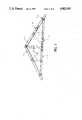
- FIG. 1shows an overall shape of the truss indicating spliced members and spliced lower chord members.
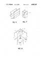
- FIG. 2shows cross section of upper chord members.
- FIG. 3shows cross section of lower chord members.
- FIG. 4shows cross section of web members.
- FIG. 5shows rolled-to-fit section of upper chord members that is used splicing.
- FIG. 6shows rolled-to-fit section of lower chord member that is used splicing.
- FIG. 7shows a segment of a web member that is used for heel reinforcing load bearing end joints.
- FIG. 8shows detail of the apex of the truss with doubled web member a king post.
- FIG. 9shows detail of a load bearing end joint with vertical heel reinforcement in the joint.
- FIG. 1shows a typical assembled truss showing an exterior splicing section 8, splicing two of the upper chord members and an exterior lower chord splicing section 9 in the lower chord unit 2.
- the U shape of the lower chord 2is facing up while the U shape of upper chord 1 is facing downward so that web members 3 fit snugly into upper and lower chord units 1 and 2 respectively.
- double web members 3 fastened together with self tapping screwsmay be used as the king post with the vertical members 3 fastened into the apex of the truss and to the center point of the lower chord 2.
- the apex of the trussmay not be at the center and the king post, which could be a larger web member, would then drop vertically from the apex to fasten into the bottom chord 2 at a point below the truss apex but not at the center of the bottom chord 2.
- Load bearing joint 5is shown in more detail in FIG. 9.
- FIG. 2we show a cross section of upper chord 1 with two rolled out reinforcing flanges 6 and with three rolled in reinforcing ribs 15 that may be 1/8" high in each of the legs and with two rolled in reinforcing ribs 16 in the base of the chord 1.
- FIG. 3we show a cross section of lower chord 2 with the rolled flat reinforcing flange 7.
- This rolled flat flangeallows the end of lower chord 2 to slide into upper chord 1 to form load bearing joint 5 which is shown in detail in FIG. 9.
- the rolled out reinforcing ribs 17 and the rolled in reinforcing ribs 18may be only 1/8" in height and there will be sufficient flexibility in chords 1 and 2 to allows rigid fastening with self tapping screws.
- FIG. 4we show a cross section of web member 3. Two rolled in reinforcing ribs 19 are shown in this member.
- FIG. 5we show splicing section 8 that is shaped exactly like the upper chord 1 but is rolled-to-fit either over or into the upper chord 1 in order to allow splicing by butting two upper chord 1 members together and fastening the closely fitting splicing section 8 over the butted ends and fastening rigidly with a plurality of self tapping screws.
- FIG. 6we show a splicing section 9 used to splice lower chord members 2 together in a similar manner as described for the upper chord members.
- FIG. 7we show a segment 13 of a web member 3 that may be approximately 5" long that is used inside of load bearing joint 5 as shown in detail in FIG. 9.
- FIG. 8we show in detail the connection of chord members 1 and web members 3 at the apex of the truss.
- a portion of flange 6 of one end of chord 1is removed and the other chord 1 end is deformed slightly outward to fit over the end with the flange portion removed and the ends of two web members 3 which may be fastened back to back with self tapping screws 10 to form a king post, slide into the apex.
- Self tapping screws 10 on each side of the apexgo through the ends of two chord members 1 and 2 and through the ends of web members 3, that form the king post, giving a rigid connection at the truss apex.
- FIG. 9we show details of load bearing joints 5 which are at each end of the truss. Heel reinforcing segments 13 slide inside the end of lower chord 2 in a vertical position and this end of lower chord 2 is then pushed into the slightly bulged out end of upper chord 1 and self tapping screws 10 are used to fasten chord member 1, chord member 2, and segments 13 together to form load bearing joint 5. A portion of the wall below the load bearing joint 5 may be reinforced with an extra or larger stud 20.
Landscapes
- Engineering & Computer Science (AREA)
- Architecture (AREA)
- Civil Engineering (AREA)
- Structural Engineering (AREA)
- Joining Of Building Structures In Genera (AREA)
- Rod-Shaped Construction Members (AREA)
Abstract
Description
Claims (2)
Priority Applications (3)
| Application Number | Priority Date | Filing Date | Title |
|---|---|---|---|
| US07/378,280US4982545A (en) | 1989-07-10 | 1989-07-10 | Economical steel roof truss |
| PCT/US1990/003780WO1991000944A2 (en) | 1989-07-10 | 1990-07-05 | An economical steel roof truss |
| AU60386/90AAU6038690A (en) | 1989-07-10 | 1990-07-05 | An economical steel roof truss |
Applications Claiming Priority (1)
| Application Number | Priority Date | Filing Date | Title |
|---|---|---|---|
| US07/378,280US4982545A (en) | 1989-07-10 | 1989-07-10 | Economical steel roof truss |
Publications (1)
| Publication Number | Publication Date |
|---|---|
| US4982545Atrue US4982545A (en) | 1991-01-08 |
Family
ID=23492472
Family Applications (1)
| Application Number | Title | Priority Date | Filing Date |
|---|---|---|---|
| US07/378,280Expired - LifetimeUS4982545A (en) | 1989-07-10 | 1989-07-10 | Economical steel roof truss |
Country Status (3)
| Country | Link |
|---|---|
| US (1) | US4982545A (en) |
| AU (1) | AU6038690A (en) |
| WO (1) | WO1991000944A2 (en) |
Cited By (61)
| Publication number | Priority date | Publication date | Assignee | Title |
|---|---|---|---|---|
| US5159792A (en)* | 1991-03-11 | 1992-11-03 | Pomento Patrick G | Roof truss building |
| WO1994015041A1 (en)* | 1992-12-18 | 1994-07-07 | Garry Randall Hart | Precision structural system |
| US5463837A (en)* | 1994-01-13 | 1995-11-07 | Dry; Daniel J. | Metal roof truss |
| WO1996005384A1 (en)* | 1994-08-16 | 1996-02-22 | Byntech Pty. Ltd. | Building truss |
| AU667180B3 (en)* | 1994-05-13 | 1996-03-07 | Sanjan Pty. Ltd. | Improved building components and systems |
| US5577353A (en)* | 1995-01-27 | 1996-11-26 | Simpson; William G. | Steel frame building system and truss assembly for use therein |
| WO1998011307A1 (en)* | 1996-09-10 | 1998-03-19 | Alpine Engineered Products, Inc. | Hinged pitch break connector |
| US5749407A (en)* | 1997-03-18 | 1998-05-12 | Amarr Company | Folding garage door with reinforcing struts |
| US5761873A (en)* | 1991-04-05 | 1998-06-09 | Slater; Jack | Web, beam and frame system for a building structure |
| WO1998029667A1 (en)* | 1996-12-30 | 1998-07-09 | Sahramaa Kimmo J | Joining metal members |
| US5806265A (en)* | 1996-01-25 | 1998-09-15 | Sluiter; Scott E. | Metal truss joining gusset |
| US5865008A (en)* | 1997-10-14 | 1999-02-02 | Bethlehem Steel Corporation | Structural shape for use in frame construction |
| US5901522A (en)* | 1995-03-15 | 1999-05-11 | Slater; Jack | Collapsible building truss |
| RU2148133C1 (en)* | 1998-07-07 | 2000-04-27 | Сибирский государственный индустриальный университет | Method for creation of structural layouts of construction trusses |
| WO2001083906A1 (en)* | 2000-04-27 | 2001-11-08 | Millers Global Enterprises Pty Ltd | An improved roof truss assembly |
| WO2001092659A1 (en)* | 2000-05-26 | 2001-12-06 | Consolidated Systems, Inc. | Light gauge metal truss system and method |
| US6519900B1 (en)* | 2000-06-30 | 2003-02-18 | Turnkey Schools Of America | Modular school building system |
| US6553736B2 (en)* | 2000-12-26 | 2003-04-29 | Antonio Montanaro | Interlocking truss system |
| US6643981B2 (en) | 2001-08-20 | 2003-11-11 | Evelio Pina | Form assembly for forming an eave, a roof slab, and a perimeter beam in a monolithic structure |
| WO2003057931A3 (en)* | 2002-01-07 | 2003-12-18 | Watson Dennis P | Cold-formed steel joists |
| EP1297229A4 (en)* | 2000-06-27 | 2004-06-09 | Nci Building Systems L P | Structural member for use in the construction of buildings |
| US20040139690A1 (en)* | 2001-08-20 | 2004-07-22 | Evelio Pina | Form assembly for forming an eave, a roof slab, and a perimeter beam in a monolithic structure and method of forming the same |
| US20050086893A1 (en)* | 2003-10-24 | 2005-04-28 | Moody Donald R. | Metal truss |
| US6964140B2 (en) | 2000-07-03 | 2005-11-15 | Walker Steven H | Structural metal member for use in a roof truss or a floor joist |
| US20060123733A1 (en)* | 2004-12-09 | 2006-06-15 | Moody Donald R | Roof truss |
| US20060144005A1 (en)* | 2004-12-30 | 2006-07-06 | United States Gypsum Company | Non-combustible reinforced cementitious lightweight panels and metal frame system for flooring |
| US20060168906A1 (en)* | 2005-01-27 | 2006-08-03 | United States Gypsum Company | Non-combustible reinforced cementitious lighweight panels and metal frame system for a fire wall and other fire resistive assemblies |
| US20060174572A1 (en)* | 2005-01-27 | 2006-08-10 | United States Gypsum Company | Non-combustible reinforced cementitious lightweight panels and metal frame system for shear walls |
| US20060185267A1 (en)* | 2005-01-27 | 2006-08-24 | United States Gypsum Company | Non-combustible reinforced cementitious lightweight panels and metal frame system for roofing |
| WO2005056947A3 (en)* | 2003-12-09 | 2006-10-19 | Nucon Steel Corp | Roof truss |
| US20070056245A1 (en)* | 2004-09-09 | 2007-03-15 | Dennis Edmondson | Slotted metal truss and joist with supplemental flanges |
| US20070084136A1 (en)* | 2003-11-18 | 2007-04-19 | Australian Construction Technology Pty Ltd | Butt joint connector |
| US20070151200A1 (en)* | 2006-01-03 | 2007-07-05 | Madray Steven G | Folding roof truss |
| US20070175126A1 (en)* | 2005-12-29 | 2007-08-02 | United States Gypsum Company | Reinforced Cementitious Shear Panels |
| WO2007134435A1 (en)* | 2006-05-18 | 2007-11-29 | Paradigm Focus Product Development Inc. | Light steel trusses and truss systems |
| US20070294974A1 (en)* | 2006-06-27 | 2007-12-27 | United States Gypsum Company | Non-combustible reinforced cementitious lightweight panels and metal frame system for building foundations |
| US20080141612A1 (en)* | 2006-12-15 | 2008-06-19 | Gerald Bruce Schierding | Metal truss system |
| US20080178555A1 (en)* | 2007-01-26 | 2008-07-31 | C. Green & Sons, Inc. | Tapered truss |
| US20100077692A1 (en)* | 2008-10-01 | 2010-04-01 | Dunbar David C | Metal roof truss having generally s-shaped web members |
| US20100263319A1 (en)* | 2009-04-16 | 2010-10-21 | Andre Lemyre | Top-chord bearing wooden joist and method |
| US20110203217A1 (en)* | 2010-02-19 | 2011-08-25 | Nucor Corporation | Weldless Building Structures |
| US20110219720A1 (en)* | 2008-09-08 | 2011-09-15 | Best Joists Inc. | Adjustable floor to wall connectors for use with bottom chord and web bearing joists |
| US20110265419A1 (en)* | 2008-12-31 | 2011-11-03 | Seccional Brasil SA | Metallic tower |
| US20130067837A1 (en)* | 2011-09-15 | 2013-03-21 | SR Systems, LLC | Construction System Providing Structural Integrity with Integral Seal |
| US8407966B2 (en) | 2003-10-28 | 2013-04-02 | Ispan Systems Lp | Cold-formed steel joist |
| US8528268B1 (en)* | 2010-12-02 | 2013-09-10 | Component Manufacturing Company | Trilateral bracing structure for reinforcing a building frame structure |
| US20130247485A1 (en)* | 2011-09-15 | 2013-09-26 | SR Systems, LLC | Anti-Torsion Construction System Providing Structural Integrity and Seismic Resistance |
| US8627872B2 (en) | 2010-11-10 | 2014-01-14 | Raynor Mfg., Co. | Garage door with reinforcing truncated isosceles strut construction and reinforcing strut construction |
| US8769910B2 (en) | 2010-06-10 | 2014-07-08 | Poutrelles Modernes, Ltee | Top-chord bearing joist |
| WO2014127783A1 (en)* | 2013-02-21 | 2014-08-28 | Svensson Peehr Mathias Ørnfeldt | Prefabricated roof plate element and method for its production |
| US8943776B2 (en) | 2012-09-28 | 2015-02-03 | Ispan Systems Lp | Composite steel joist |
| US9004835B2 (en) | 2010-02-19 | 2015-04-14 | Nucor Corporation | Weldless building structures |
| US9181700B2 (en) | 2007-01-26 | 2015-11-10 | Morton Building, Inc. | Tapered truss |
| US9975577B2 (en) | 2009-07-22 | 2018-05-22 | Ispan Systems Lp | Roll formed steel beam |
| CN108240069A (en)* | 2018-03-23 | 2018-07-03 | 中建二局安装工程有限公司 | A kind of large span multi-section combined truss roof structure system and its construction method |
| US20190093335A1 (en)* | 2017-09-26 | 2019-03-28 | Pravin Nanayakkara | Composite floor joist |
| US10260235B1 (en)* | 2017-09-25 | 2019-04-16 | Pravin Nanayakkara | Construction metallic trapezoidal systems |
| US20200080297A1 (en)* | 2018-08-21 | 2020-03-12 | John David Wright | Insulatable, Insulative Framework Apparatus and Methods of Making and Using Same |
| US10788066B2 (en) | 2016-05-02 | 2020-09-29 | Nucor Corporation | Double threaded standoff fastener |
| US20220106792A1 (en)* | 2020-10-02 | 2022-04-07 | Next New Concept, Inc. | Extruded Aluminum Roof Truss Manufacturing System and Methods |
| US11459755B2 (en) | 2019-07-16 | 2022-10-04 | Invent To Build Inc. | Concrete fillable steel joist |
Families Citing this family (2)
| Publication number | Priority date | Publication date | Assignee | Title |
|---|---|---|---|---|
| DE4301475A1 (en)* | 1992-02-12 | 1993-08-19 | Krupp Stahl Kaltform | Building structure separating rooms one above the other - has cold-rolled profiled girders forming auxiliary ceiling of heat-section open towards main ceiling with flanges converging and then at right angles to it |
| AUPO650097A0 (en)* | 1997-04-30 | 1997-05-29 | Weeks Peacock Quality Homes Pty Ltd | A structural member |
Citations (8)
| Publication number | Priority date | Publication date | Assignee | Title |
|---|---|---|---|---|
| US2067403A (en)* | 1933-08-31 | 1937-01-12 | William C Lea | Metal building construction |
| US2234960A (en)* | 1938-10-03 | 1941-03-18 | Building frame structure | |
| CA476296A (en)* | 1951-08-21 | S. Shannon Harold | Roof construction | |
| US2642825A (en)* | 1951-11-01 | 1953-06-23 | Copco Steel And Engineering Co | Foldable and compactable truss and stud support |
| US3668828A (en)* | 1970-03-10 | 1972-06-13 | George E Nicholas | Building construction framework with receivers for bracing means |
| US4435940A (en)* | 1982-05-10 | 1984-03-13 | Angeles Metal Trim Co. | Metal building truss |
| US4551957A (en)* | 1983-05-23 | 1985-11-12 | Madray Herbert R | Building construction |
| US4616453A (en)* | 1982-05-20 | 1986-10-14 | Sheppard Jr Isaac | Light gauge steel building system |
- 1989
- 1989-07-10USUS07/378,280patent/US4982545A/ennot_activeExpired - Lifetime
- 1990
- 1990-07-05WOPCT/US1990/003780patent/WO1991000944A2/enunknown
- 1990-07-05AUAU60386/90Apatent/AU6038690A/ennot_activeAbandoned
Patent Citations (8)
| Publication number | Priority date | Publication date | Assignee | Title |
|---|---|---|---|---|
| CA476296A (en)* | 1951-08-21 | S. Shannon Harold | Roof construction | |
| US2067403A (en)* | 1933-08-31 | 1937-01-12 | William C Lea | Metal building construction |
| US2234960A (en)* | 1938-10-03 | 1941-03-18 | Building frame structure | |
| US2642825A (en)* | 1951-11-01 | 1953-06-23 | Copco Steel And Engineering Co | Foldable and compactable truss and stud support |
| US3668828A (en)* | 1970-03-10 | 1972-06-13 | George E Nicholas | Building construction framework with receivers for bracing means |
| US4435940A (en)* | 1982-05-10 | 1984-03-13 | Angeles Metal Trim Co. | Metal building truss |
| US4616453A (en)* | 1982-05-20 | 1986-10-14 | Sheppard Jr Isaac | Light gauge steel building system |
| US4551957A (en)* | 1983-05-23 | 1985-11-12 | Madray Herbert R | Building construction |
Cited By (120)
| Publication number | Priority date | Publication date | Assignee | Title |
|---|---|---|---|---|
| US5159792A (en)* | 1991-03-11 | 1992-11-03 | Pomento Patrick G | Roof truss building |
| US5761873A (en)* | 1991-04-05 | 1998-06-09 | Slater; Jack | Web, beam and frame system for a building structure |
| WO1994015041A1 (en)* | 1992-12-18 | 1994-07-07 | Garry Randall Hart | Precision structural system |
| US5463837A (en)* | 1994-01-13 | 1995-11-07 | Dry; Daniel J. | Metal roof truss |
| AU667180B3 (en)* | 1994-05-13 | 1996-03-07 | Sanjan Pty. Ltd. | Improved building components and systems |
| WO1996005384A1 (en)* | 1994-08-16 | 1996-02-22 | Byntech Pty. Ltd. | Building truss |
| US5577353A (en)* | 1995-01-27 | 1996-11-26 | Simpson; William G. | Steel frame building system and truss assembly for use therein |
| US5901522A (en)* | 1995-03-15 | 1999-05-11 | Slater; Jack | Collapsible building truss |
| US5806265A (en)* | 1996-01-25 | 1998-09-15 | Sluiter; Scott E. | Metal truss joining gusset |
| US6076325A (en)* | 1996-01-25 | 2000-06-20 | Sluiter; Scott E. | Metal truss joining gusset |
| US5890339A (en)* | 1996-09-10 | 1999-04-06 | Alpine Engineered Products, Inc. | Hinged pitch break connector |
| WO1998011307A1 (en)* | 1996-09-10 | 1998-03-19 | Alpine Engineered Products, Inc. | Hinged pitch break connector |
| WO1998029667A1 (en)* | 1996-12-30 | 1998-07-09 | Sahramaa Kimmo J | Joining metal members |
| US5839848A (en)* | 1996-12-30 | 1998-11-24 | Sahramaa; Kimmo J | Joining metal members |
| US5749407A (en)* | 1997-03-18 | 1998-05-12 | Amarr Company | Folding garage door with reinforcing struts |
| US5865008A (en)* | 1997-10-14 | 1999-02-02 | Bethlehem Steel Corporation | Structural shape for use in frame construction |
| WO1999019577A1 (en) | 1997-10-14 | 1999-04-22 | Bethlehem Steel Corporation | Structural shape for use in frame construction |
| US20040050011A1 (en)* | 1997-10-14 | 2004-03-18 | Isg Technologies Inc. | Structural shape for use in frame construction |
| US6817155B2 (en)* | 1997-10-14 | 2004-11-16 | Steel Construction Systems | Structural shape for use in frame construction |
| RU2148133C1 (en)* | 1998-07-07 | 2000-04-27 | Сибирский государственный индустриальный университет | Method for creation of structural layouts of construction trusses |
| WO2001083906A1 (en)* | 2000-04-27 | 2001-11-08 | Millers Global Enterprises Pty Ltd | An improved roof truss assembly |
| US7093401B2 (en) | 2000-05-26 | 2006-08-22 | Renaissance Steel, Llc | Light gauge metal truss system and method |
| US6658809B2 (en)* | 2000-05-26 | 2003-12-09 | Consolidated Systems, Inc. | Light gauge metal truss system and method |
| US20040118073A1 (en)* | 2000-05-26 | 2004-06-24 | Collins Harry J. | Light gauge metal truss system and method |
| US20040118072A1 (en)* | 2000-05-26 | 2004-06-24 | Collins Harry J. | Light gauge metal truss system and method |
| WO2001092659A1 (en)* | 2000-05-26 | 2001-12-06 | Consolidated Systems, Inc. | Light gauge metal truss system and method |
| US7546714B2 (en) | 2000-06-27 | 2009-06-16 | Nci Group, Inc. | Building joist with saddle support at ends thereof |
| US20070245675A1 (en)* | 2000-06-27 | 2007-10-25 | Nci Buildings Systems, L.P. | Structural member for use in the construction of buildings |
| EP1297229A4 (en)* | 2000-06-27 | 2004-06-09 | Nci Building Systems L P | Structural member for use in the construction of buildings |
| US20060179781A1 (en)* | 2000-06-27 | 2006-08-17 | Nci Buildings Systems, L.P. | Structural member for use in the construction of buildings |
| US7240463B2 (en)* | 2000-06-27 | 2007-07-10 | Nci Building Systems, L.P. | Structural member for use in the construction of buildings |
| US6519900B1 (en)* | 2000-06-30 | 2003-02-18 | Turnkey Schools Of America | Modular school building system |
| US6907695B2 (en) | 2000-06-30 | 2005-06-21 | Turnkey Schools Of America | Modular school building system |
| US6964140B2 (en) | 2000-07-03 | 2005-11-15 | Walker Steven H | Structural metal member for use in a roof truss or a floor joist |
| US6553736B2 (en)* | 2000-12-26 | 2003-04-29 | Antonio Montanaro | Interlocking truss system |
| US20040139690A1 (en)* | 2001-08-20 | 2004-07-22 | Evelio Pina | Form assembly for forming an eave, a roof slab, and a perimeter beam in a monolithic structure and method of forming the same |
| US6643981B2 (en) | 2001-08-20 | 2003-11-11 | Evelio Pina | Form assembly for forming an eave, a roof slab, and a perimeter beam in a monolithic structure |
| WO2003057931A3 (en)* | 2002-01-07 | 2003-12-18 | Watson Dennis P | Cold-formed steel joists |
| US20060053732A1 (en)* | 2002-01-07 | 2006-03-16 | Watson Dennis P | Cold-formed steel joists |
| US7513085B2 (en) | 2003-10-24 | 2009-04-07 | Nucon Steel Corporation | Metal truss |
| US20050086893A1 (en)* | 2003-10-24 | 2005-04-28 | Moody Donald R. | Metal truss |
| US8407966B2 (en) | 2003-10-28 | 2013-04-02 | Ispan Systems Lp | Cold-formed steel joist |
| US20070084136A1 (en)* | 2003-11-18 | 2007-04-19 | Australian Construction Technology Pty Ltd | Butt joint connector |
| US7735294B2 (en) | 2003-12-09 | 2010-06-15 | Nucon Steel Corporation | Roof truss |
| US8006461B2 (en) | 2003-12-09 | 2011-08-30 | Nucon Steel Corporation | Roof truss |
| WO2005056947A3 (en)* | 2003-12-09 | 2006-10-19 | Nucon Steel Corp | Roof truss |
| US20080295448A1 (en)* | 2003-12-09 | 2008-12-04 | Nucon Steel Corporation | Roof truss |
| US20080295442A1 (en)* | 2003-12-09 | 2008-12-04 | Nucon Steel Corporation | Roof truss |
| US20070056245A1 (en)* | 2004-09-09 | 2007-03-15 | Dennis Edmondson | Slotted metal truss and joist with supplemental flanges |
| US7866112B2 (en)* | 2004-09-09 | 2011-01-11 | Dennis Edmondson | Slotted metal truss and joist with supplemental flanges |
| US20060123733A1 (en)* | 2004-12-09 | 2006-06-15 | Moody Donald R | Roof truss |
| US7409804B2 (en)* | 2004-12-09 | 2008-08-12 | Nucon Steel Corporation | Roof truss |
| US20060144005A1 (en)* | 2004-12-30 | 2006-07-06 | United States Gypsum Company | Non-combustible reinforced cementitious lightweight panels and metal frame system for flooring |
| US20110056159A1 (en)* | 2004-12-30 | 2011-03-10 | United States Gypsum Company | Non-combustible reinforced cementitious lightweight panels and metal frame system for flooring |
| US8069633B2 (en) | 2004-12-30 | 2011-12-06 | U.S. Gypsum Company | Non-combustible reinforced cementitious lightweight panels and metal frame system for flooring |
| US7849648B2 (en) | 2004-12-30 | 2010-12-14 | United States Gypsum Company | Non-combustible reinforced cementitious lightweight panels and metal frame system for flooring |
| US8079198B2 (en) | 2005-01-27 | 2011-12-20 | United States Gypsum Company | Non-combustible reinforced cementitious lightweight panels and metal frame system for shear walls |
| US7849650B2 (en) | 2005-01-27 | 2010-12-14 | United States Gypsum Company | Non-combustible reinforced cementitious lightweight panels and metal frame system for a fire wall and other fire resistive assemblies |
| US8065852B2 (en) | 2005-01-27 | 2011-11-29 | U.S. Gypsum Company | Non-combustible reinforced cementitious lightweight panels and metal frame system for roofing |
| US20060168906A1 (en)* | 2005-01-27 | 2006-08-03 | United States Gypsum Company | Non-combustible reinforced cementitious lighweight panels and metal frame system for a fire wall and other fire resistive assemblies |
| US20060185267A1 (en)* | 2005-01-27 | 2006-08-24 | United States Gypsum Company | Non-combustible reinforced cementitious lightweight panels and metal frame system for roofing |
| US20110113715A1 (en)* | 2005-01-27 | 2011-05-19 | United States Gypsum Company | Non-combustible reinforced cementitious lightweight panels and metal frame system for shear walls |
| US7841148B2 (en) | 2005-01-27 | 2010-11-30 | United States Gypsum Company | Non-combustible reinforced cementitious lightweight panels and metal frame system for roofing |
| US20110192100A1 (en)* | 2005-01-27 | 2011-08-11 | United States Gypsum Company | Non-combustible reinforced cementitious lightweight panels and metal frame system for a fire wall and other fire resistive assemblies |
| US7849649B2 (en) | 2005-01-27 | 2010-12-14 | United States Gypsum Company | Non-combustible reinforced cementitious lightweight panels and metal frame system for shear walls |
| US20060174572A1 (en)* | 2005-01-27 | 2006-08-10 | United States Gypsum Company | Non-combustible reinforced cementitious lightweight panels and metal frame system for shear walls |
| US8122679B2 (en) | 2005-01-27 | 2012-02-28 | United States Gypsum Company | Non-combustible reinforced cementitious lightweight panels and metal frame system for a fire wall and other fire resistive assemblies |
| US20110041443A1 (en)* | 2005-01-27 | 2011-02-24 | United States Gypsum Company | Non-combustible reinforced cementitious lightweight panels and metal frame system for roofing |
| US20070175126A1 (en)* | 2005-12-29 | 2007-08-02 | United States Gypsum Company | Reinforced Cementitious Shear Panels |
| US8065853B2 (en) | 2005-12-29 | 2011-11-29 | U.S. Gypsum Company | Reinforced cementitious shear panels |
| US20110056156A1 (en)* | 2005-12-29 | 2011-03-10 | United States Gypsum Company | Reinforced cementitious shear panels |
| US7845130B2 (en) | 2005-12-29 | 2010-12-07 | United States Gypsum Company | Reinforced cementitious shear panels |
| US20070151200A1 (en)* | 2006-01-03 | 2007-07-05 | Madray Steven G | Folding roof truss |
| US8726606B2 (en) | 2006-05-18 | 2014-05-20 | Paradigm Focus Product Development Inc. | Light steel trusses and truss systems |
| WO2007134435A1 (en)* | 2006-05-18 | 2007-11-29 | Paradigm Focus Product Development Inc. | Light steel trusses and truss systems |
| US20110061316A1 (en)* | 2006-06-27 | 2011-03-17 | United States Gypsum Company | Non-combustible reinforced cementitious lightweight panels and metal frame system for building foundations |
| US20070294974A1 (en)* | 2006-06-27 | 2007-12-27 | United States Gypsum Company | Non-combustible reinforced cementitious lightweight panels and metal frame system for building foundations |
| US8061108B2 (en) | 2006-06-27 | 2011-11-22 | U.S. Gypsum Company | Non-combustible reinforced cementitious lightweight panels and metal frame system for building foundations |
| US7870698B2 (en) | 2006-06-27 | 2011-01-18 | United States Gypsum Company | Non-combustible reinforced cementitious lightweight panels and metal frame system for building foundations |
| US20080141612A1 (en)* | 2006-12-15 | 2008-06-19 | Gerald Bruce Schierding | Metal truss system |
| US7669379B2 (en)* | 2006-12-15 | 2010-03-02 | Gerald Bruce Schierding | Metal truss system |
| US9181700B2 (en) | 2007-01-26 | 2015-11-10 | Morton Building, Inc. | Tapered truss |
| US9689163B2 (en) | 2007-01-26 | 2017-06-27 | Morton Building, Inc. | Tapered truss |
| US20080178555A1 (en)* | 2007-01-26 | 2008-07-31 | C. Green & Sons, Inc. | Tapered truss |
| US20110219720A1 (en)* | 2008-09-08 | 2011-09-15 | Best Joists Inc. | Adjustable floor to wall connectors for use with bottom chord and web bearing joists |
| US8950151B2 (en) | 2008-09-08 | 2015-02-10 | Ispan Systems Lp | Adjustable floor to wall connectors for use with bottom chord and web bearing joists |
| US20100077692A1 (en)* | 2008-10-01 | 2010-04-01 | Dunbar David C | Metal roof truss having generally s-shaped web members |
| US8141318B2 (en)* | 2008-10-01 | 2012-03-27 | Illinois Tool Works, Inc. | Metal roof truss having generally S-shaped web members |
| US8534025B2 (en)* | 2008-12-31 | 2013-09-17 | Seccional Brasil SA | Metallic tower |
| US20110265419A1 (en)* | 2008-12-31 | 2011-11-03 | Seccional Brasil SA | Metallic tower |
| US8122676B2 (en) | 2009-04-16 | 2012-02-28 | Solive Ajouree 2000 Inc. | Top-chord bearing wooden joist |
| US20100263319A1 (en)* | 2009-04-16 | 2010-10-21 | Andre Lemyre | Top-chord bearing wooden joist and method |
| US9975577B2 (en) | 2009-07-22 | 2018-05-22 | Ispan Systems Lp | Roll formed steel beam |
| US20110203217A1 (en)* | 2010-02-19 | 2011-08-25 | Nucor Corporation | Weldless Building Structures |
| US8529178B2 (en) | 2010-02-19 | 2013-09-10 | Nucor Corporation | Weldless building structures |
| US8636456B2 (en) | 2010-02-19 | 2014-01-28 | Nucor Corporation | Weldless building structures |
| US9004835B2 (en) | 2010-02-19 | 2015-04-14 | Nucor Corporation | Weldless building structures |
| US9267527B2 (en) | 2010-02-19 | 2016-02-23 | Nucor Corporation | Weldless building structures |
| US8769910B2 (en) | 2010-06-10 | 2014-07-08 | Poutrelles Modernes, Ltee | Top-chord bearing joist |
| US8627872B2 (en) | 2010-11-10 | 2014-01-14 | Raynor Mfg., Co. | Garage door with reinforcing truncated isosceles strut construction and reinforcing strut construction |
| US8528268B1 (en)* | 2010-12-02 | 2013-09-10 | Component Manufacturing Company | Trilateral bracing structure for reinforcing a building frame structure |
| US8726581B2 (en)* | 2011-09-15 | 2014-05-20 | SR Systems, LLC | Construction system providing structural integrity with integral seal |
| US8919050B2 (en)* | 2011-09-15 | 2014-12-30 | SR Systems, LLC | Anti-torsion construction system providing structural integrity and seismic resistance |
| US20130247485A1 (en)* | 2011-09-15 | 2013-09-26 | SR Systems, LLC | Anti-Torsion Construction System Providing Structural Integrity and Seismic Resistance |
| US20130067837A1 (en)* | 2011-09-15 | 2013-03-21 | SR Systems, LLC | Construction System Providing Structural Integrity with Integral Seal |
| US8943776B2 (en) | 2012-09-28 | 2015-02-03 | Ispan Systems Lp | Composite steel joist |
| US10030390B2 (en) | 2013-02-21 | 2018-07-24 | Peehr Mathias Ørnfeldt Svensson | Prefabricated roof plate element and method for its production |
| WO2014127783A1 (en)* | 2013-02-21 | 2014-08-28 | Svensson Peehr Mathias Ørnfeldt | Prefabricated roof plate element and method for its production |
| US10788066B2 (en) | 2016-05-02 | 2020-09-29 | Nucor Corporation | Double threaded standoff fastener |
| US11815123B2 (en) | 2016-05-02 | 2023-11-14 | Nucor Corporation | Double threaded standoff fastener |
| US10260235B1 (en)* | 2017-09-25 | 2019-04-16 | Pravin Nanayakkara | Construction metallic trapezoidal systems |
| US20190093335A1 (en)* | 2017-09-26 | 2019-03-28 | Pravin Nanayakkara | Composite floor joist |
| US10538906B2 (en)* | 2017-09-26 | 2020-01-21 | Pravin Nanayakkara | Composite floor joist |
| CN108240069B (en)* | 2018-03-23 | 2023-10-20 | 中建二局安装工程有限公司 | Large-span multi-section combined truss roof structure system and construction method thereof |
| CN108240069A (en)* | 2018-03-23 | 2018-07-03 | 中建二局安装工程有限公司 | A kind of large span multi-section combined truss roof structure system and its construction method |
| US20200080297A1 (en)* | 2018-08-21 | 2020-03-12 | John David Wright | Insulatable, Insulative Framework Apparatus and Methods of Making and Using Same |
| US11808031B2 (en) | 2018-08-21 | 2023-11-07 | J. David Wright LLC | Insulatable, insulative framework apparatus and methods of making and using same |
| US11066826B2 (en)* | 2018-08-21 | 2021-07-20 | John David Wright | Insulatable, insulative framework apparatus and methods of making and using same |
| US11459755B2 (en) | 2019-07-16 | 2022-10-04 | Invent To Build Inc. | Concrete fillable steel joist |
| US20220106792A1 (en)* | 2020-10-02 | 2022-04-07 | Next New Concept, Inc. | Extruded Aluminum Roof Truss Manufacturing System and Methods |
Also Published As
| Publication number | Publication date |
|---|---|
| WO1991000944A2 (en) | 1991-01-24 |
| AU6038690A (en) | 1991-02-06 |
| WO1991000944A3 (en) | 1991-02-21 |
Similar Documents
| Publication | Publication Date | Title |
|---|---|---|
| US4982545A (en) | Economical steel roof truss | |
| US4318635A (en) | Culvert structure having corrugated ribbing support | |
| US2284898A (en) | Structural system | |
| US1883376A (en) | Building construction | |
| US6293071B1 (en) | Antiseismic spiral stirrups for reinforcement of load bearing structural elements | |
| US5901522A (en) | Collapsible building truss | |
| US4986051A (en) | Roof truss and beam therefor | |
| US4349996A (en) | Integrated roof system | |
| US4409771A (en) | Sheet metal beam | |
| US3849961A (en) | T-clip truss and rafter system of roof construction | |
| US4315386A (en) | Portal building structures | |
| US3066771A (en) | Prefabricated bridge deck panels | |
| US4675238A (en) | Metal decking | |
| US3474578A (en) | Roof girder construction | |
| KR20140051434A (en) | Wide span static structure | |
| US3157251A (en) | Building construction | |
| MXPA03004874A (en) | Cellular-core structural panel, and building structure incorporating same. | |
| EP1418284A1 (en) | A truss tie-down method and apparatus | |
| US20150059268A9 (en) | Prestressed and cambered steel decking floor system | |
| US4862661A (en) | Enclosed structure and method of construction | |
| US4579785A (en) | Metal decking | |
| US4947599A (en) | Trussed girder with pre-tension member therein | |
| US4432184A (en) | Support for the construction of buildings | |
| US2943366A (en) | Unit column building construction | |
| US3313074A (en) | Roof and upper floor construction |
Legal Events
| Date | Code | Title | Description |
|---|---|---|---|
| AS | Assignment | Owner name:HEMMING TECHNOLOGIES, INC., ARIZONA Free format text:PATENT TRANSFER DOCUMENT;ASSIGNOR:STROMBACK, JOHN G.H.;REEL/FRAME:006498/0394 Effective date:19930120 Owner name:JOHN G. H. STROMBACK, ARIZONA Free format text:PATENT SALE AGREEMENT;ASSIGNOR:STROMBACK, GUSTAV M.;REEL/FRAME:006498/0391 Effective date:19920106 | |
| REMI | Maintenance fee reminder mailed | ||
| FEPP | Fee payment procedure | Free format text:PETITION RELATED TO MAINTENANCE FEES FILED (ORIGINAL EVENT CODE: PMFP); ENTITY STATUS OF PATENT OWNER: LARGE ENTITY | |
| FEPP | Fee payment procedure | Free format text:PETITION RELATED TO MAINTENANCE FEES GRANTED (ORIGINAL EVENT CODE: PMFG); ENTITY STATUS OF PATENT OWNER: LARGE ENTITY | |
| REIN | Reinstatement after maintenance fee payment confirmed | ||
| FPAY | Fee payment | Year of fee payment:4 | |
| SULP | Surcharge for late payment | ||
| FP | Lapsed due to failure to pay maintenance fee | Effective date:19950111 | |
| STCF | Information on status: patent grant | Free format text:PATENTED CASE | |
| DP | Notification of acceptance of delayed payment of maintenance fee | ||
| FPAY | Fee payment | Year of fee payment:8 | |
| FPAY | Fee payment | Year of fee payment:12 | |
| AS | Assignment | Owner name:NUCOR CORPORATION, NORTH CAROLINA Free format text:MEMORANDUM OF LICENSE INTEREST;ASSIGNOR:HEMMING TECHNOLOGIES, INC.;REEL/FRAME:012653/0605 Effective date:20020226 | |
| AS | Assignment | Owner name:NUCON STEEL CORPORATION, TEXAS Free format text:CORRECTIVE PREVIOUSLY RECORDED AT REEL 014301 FRAME 0465 OF ERRORNEOUSLY RECORDED PATENT NUMBER 4942545. THE CONVEYING PARTY HEREBY CONFIRMS THE ASSIGNMENT OF THE ENTIRE INTEREST.;ASSIGNOR:HEMMING TECHNOLOGIES, INC.;REEL/FRAME:015612/0896 Effective date:20030711 | |
| AS | Assignment | Owner name:NUCONSTEEL CORPORATION, TEXAS Free format text:CHANGE OF NAME;ASSIGNOR:NUCON STEEL CORPORATION;REEL/FRAME:028776/0858 Effective date:20090717 |