US4981479A - Ocular treatment apparatus - Google Patents
Ocular treatment apparatusDownload PDFInfo
- Publication number
- US4981479A US4981479AUS07/452,782US45278289AUS4981479AUS 4981479 AUS4981479 AUS 4981479AUS 45278289 AUS45278289 AUS 45278289AUS 4981479 AUS4981479 AUS 4981479A
- Authority
- US
- United States
- Prior art keywords
- medicament
- eye
- housing
- ocular
- eyelid
- Prior art date
- Legal status (The legal status is an assumption and is not a legal conclusion. Google has not performed a legal analysis and makes no representation as to the accuracy of the status listed.)
- Expired - Lifetime
Links
- 239000003814drugSubstances0.000claimsabstractdescription158
- 210000000744eyelidAnatomy0.000claimsabstractdescription96
- 230000001815facial effectEffects0.000claimsabstractdescription62
- 210000001519tissueAnatomy0.000claimsabstractdescription59
- 210000003717douglas' pouchAnatomy0.000claimsabstractdescription48
- 210000003128headAnatomy0.000claimsdescription14
- 210000000988bone and boneAnatomy0.000claimsdescription5
- 210000004087corneaAnatomy0.000claimsdescription5
- 230000004044responseEffects0.000claimsdescription4
- 210000001508eyeAnatomy0.000description104
- 239000006196dropSubstances0.000description25
- 239000007788liquidSubstances0.000description22
- 238000007373indentationMethods0.000description19
- 238000006073displacement reactionMethods0.000description13
- 230000007246mechanismEffects0.000description8
- 230000004397blinkingEffects0.000description7
- 210000005252bulbus oculiAnatomy0.000description7
- 229910000831SteelInorganic materials0.000description6
- 230000002093peripheral effectEffects0.000description6
- 239000010959steelSubstances0.000description6
- 230000008901benefitEffects0.000description5
- 239000003889eye dropSubstances0.000description5
- 239000000463materialSubstances0.000description5
- 238000003466weldingMethods0.000description5
- 230000000994depressogenic effectEffects0.000description4
- 206010047531Visual acuity reducedDiseases0.000description3
- 210000000795conjunctivaAnatomy0.000description3
- 230000005484gravityEffects0.000description3
- 244000273618Sphenoclea zeylanicaSpecies0.000description2
- 208000027418Wounds and injuryDiseases0.000description2
- 230000006378damageEffects0.000description2
- 230000000881depressing effectEffects0.000description2
- 229940012356eye dropsDrugs0.000description2
- 229920002457flexible plasticPolymers0.000description2
- 208000014674injuryDiseases0.000description2
- 210000004279orbitAnatomy0.000description2
- 238000003825pressingMethods0.000description2
- 230000035945sensitivityEffects0.000description2
- 239000007787solidSubstances0.000description2
- 206010011878DeafnessDiseases0.000description1
- 230000009471actionEffects0.000description1
- 239000000443aerosolSubstances0.000description1
- 230000004323axial lengthEffects0.000description1
- 238000006243chemical reactionMethods0.000description1
- 238000004891communicationMethods0.000description1
- 238000010276constructionMethods0.000description1
- 238000000203droplet dispensingMethods0.000description1
- 230000004438eyesightEffects0.000description1
- 239000012530fluidSubstances0.000description1
- 239000012535impuritySubstances0.000description1
- 239000002184metalSubstances0.000description1
- 238000000034methodMethods0.000description1
- 238000012986modificationMethods0.000description1
- 230000004048modificationEffects0.000description1
- 239000002245particleSubstances0.000description1
- 229920003023plasticPolymers0.000description1
- 230000008569processEffects0.000description1
- 239000003380propellantSubstances0.000description1
- 210000001747pupilAnatomy0.000description1
- 230000000284resting effectEffects0.000description1
- 230000000717retained effectEffects0.000description1
- 238000005096rolling processMethods0.000description1
- 230000007306turnoverEffects0.000description1
Images


Classifications
- A—HUMAN NECESSITIES
- A61—MEDICAL OR VETERINARY SCIENCE; HYGIENE
- A61F—FILTERS IMPLANTABLE INTO BLOOD VESSELS; PROSTHESES; DEVICES PROVIDING PATENCY TO, OR PREVENTING COLLAPSING OF, TUBULAR STRUCTURES OF THE BODY, e.g. STENTS; ORTHOPAEDIC, NURSING OR CONTRACEPTIVE DEVICES; FOMENTATION; TREATMENT OR PROTECTION OF EYES OR EARS; BANDAGES, DRESSINGS OR ABSORBENT PADS; FIRST-AID KITS
- A61F9/00—Methods or devices for treatment of the eyes; Devices for putting in contact-lenses; Devices to correct squinting; Apparatus to guide the blind; Protective devices for the eyes, carried on the body or in the hand
- A61F9/0008—Introducing ophthalmic products into the ocular cavity or retaining products therein
- A61F9/0026—Ophthalmic product dispenser attachments to facilitate positioning near the eye
- A—HUMAN NECESSITIES
- A61—MEDICAL OR VETERINARY SCIENCE; HYGIENE
- A61F—FILTERS IMPLANTABLE INTO BLOOD VESSELS; PROSTHESES; DEVICES PROVIDING PATENCY TO, OR PREVENTING COLLAPSING OF, TUBULAR STRUCTURES OF THE BODY, e.g. STENTS; ORTHOPAEDIC, NURSING OR CONTRACEPTIVE DEVICES; FOMENTATION; TREATMENT OR PROTECTION OF EYES OR EARS; BANDAGES, DRESSINGS OR ABSORBENT PADS; FIRST-AID KITS
- A61F9/00—Methods or devices for treatment of the eyes; Devices for putting in contact-lenses; Devices to correct squinting; Apparatus to guide the blind; Protective devices for the eyes, carried on the body or in the hand
- A61F9/0008—Introducing ophthalmic products into the ocular cavity or retaining products therein
- B—PERFORMING OPERATIONS; TRANSPORTING
- B05—SPRAYING OR ATOMISING IN GENERAL; APPLYING FLUENT MATERIALS TO SURFACES, IN GENERAL
- B05B—SPRAYING APPARATUS; ATOMISING APPARATUS; NOZZLES
- B05B11/00—Single-unit hand-held apparatus in which flow of contents is produced by the muscular force of the operator at the moment of use
- B05B11/01—Single-unit hand-held apparatus in which flow of contents is produced by the muscular force of the operator at the moment of use characterised by the means producing the flow
- B05B11/10—Pump arrangements for transferring the contents from the container to a pump chamber by a sucking effect and forcing the contents out through the dispensing nozzle
- B05B11/1042—Components or details
- B05B11/1066—Pump inlet valves
- B05B11/107—Gate valves; Sliding valves
Definitions
- the present inventionis directed to ocular treatment apparatus and, in particular, to ocular treatment apparatus that can apply eye drops of liquid medicament safely and easily.
- U.S. Pat. No. 4,543,096describes and illustrates an apparatus having finger-like projections which are attached to the front of an eye drop bottle to spread the eyelids apart during the eye drop dispensing process.
- One moveable fingeris connected to a lever for depressing the lever and simultaneously causing the eyelids to spread apart while forcing a drop from the dropper bottle.
- the apparatus described in U.S. Pat. No. 4,543,096will not properly steady the eyeball nor expose the cul-de-sac. Further, the finger-like projections could cause injury to the eye if a user accidentally contacts his cornea with one of the projections.
- 4,531,944depicts an apparatus for steadying the tip of a dropper over the eye and further includes a sighting hole to distract the eye.
- this apparatusdoes not have means to expose the cul-de-sac nor keep the lower eyelid depressed.
- an ocular treatment apparatusthat is capable of simultaneously steadying the eyeball, orienting the application of the medicament, applying the medicament and exposing the cul-de-sac is desired.
- an ocular treatment apparatusfor applying liquid medicament from a reservoir.
- the apparatusincludes a tubular housing with a first open end adapted to conform to the shape of the facial area surrounding the eye socket.
- the housingis constructed and arranged to receive, hold and position a reservoir containing the liquid medicament.
- a sighting openingis included on the housing to properly orient the eye and distract the user from the drops of liquid medicament to be introduced into the eye.
- An eyelid displacement mechanismis supported on the first open end of the housing at a position diametrically opposed to the sighting opening. The displacement mechanism is adapted to evert the lower eyelid and expose the cul-de-sac.
- This combination of an eye focused at the sighting hole and an everted lower eyelidexposes the cul-de-sac so that drops of medicament dispensed into the eye will more easily and directly be applied at or near the cul-de-sac where it is temporarily retained to increase the length of time the medicament will medicate the eyeball.
- the lower eyelid displacement mechanismwill simultaneously cause drops to be emitted from the reservoir into the cul-de-sac as the lower eyelid is everted to facilitate application of the drops of liquid medicament.
- the cul-de-sacis a low sensitivity area as opposed to the cornea area. Therefore application of medicament to the cul-de-sac is more comfortable.
- the eyepiece portiondefines an opening therein having a peripheral edge shaped for conformable engagement with the facial tissue surrounding an eye.
- the inner housing memberfurther includes a body portion for receiving a vial of liquid medicament for application to the eye.
- An outer housing member of the apparatushas an open free end slideably engaged over the end of the inner housing member opposite the eyepiece portion.
- the outer housing memberdefines a medicament displacement member projecting outwardly from its end opposite the free end and projecting into the body portion of the inner housing member.
- the displacement memberis depressible against a flexible vial contained within the body portion of the inner housing member by sliding the outer housing member toward the eyepiece portion for displacing medicament from the vial and, in turn, through the opening in the eyepiece portion and into the eye.
- the apparatusfurther includes means for displacing the lower eyelid of an eye to evert the lower eyelid so that medicament released from the vial is applied to the ocular cul-de-sac of the eye.
- the means for displacing the lower eyelidpreferably include a cushion member having a substantially curved configuration.
- the cushion memberis disposed around the peripheral edge of the eyepiece portion so that the free end of the cushion member is placed between the interior surface of the eyepiece portion and facial tissue of the person.
- the other end of the cushion memberis connected to a flexible bar which, in turn, is connected on its other end to the outer housing member.
- the flexible bar memberpresses the cushion member downwardly to evert the lower eyelid when the outer housing member is moved over the inner housing member toward the eyepiece portion for application of medicament into the ocular cul-de-sac.
- the present inventionis also directed to an apparatus for applying medicament to an eye comprising an inner casing adapted to receive medicament.
- the inner casingdefines a first surface shaped to engage the facial tissue surrounding an eye.
- the inner casingfurther defines a first aperture extending therethrough. Medicament is released through the first aperture into an eye.
- An outer casing of the apparatusis coupled to the inner casing and movable relative thereto.
- the apparatusfurther comprises means for displacing the lower eyelid of an eye to expose the ocular cul-de-sac.
- the means for displacingis coupled to the outer casing.
- the apparatusfurther comprises means for dispensing medicament received within the outer casing onto the exposed ocular cul-de-sac of the eye.
- the means for dispensingis coupled to the outer casing.
- the inner casingincludes an eyecup supported on one end thereof, which defines the first surface.
- the means for displacingincludes a displacing member coupled to the outer casing.
- the displacing memberdefines a second surface adapted to engage the facial tissue below an eye.
- the second surfaceis engageable with facial tissue by moving the outer casing relative to the inner casing, to displace the facial tissue and thus displace the lower eyelid.
- the inner casingdefines at least one second aperture extending therethrough.
- the second apertureis adapted to receive the displacing member therethrough.
- the inner casingfurther defines at least one guide surface adapted to guide the displacing member toward the facial tissue below an eye.
- the apparatusfurther comprises a vial supported within the inner casing.
- the vialis adapted to hold medicament and to release medicament in response to the means for dispensing, upon moving the outer casing relative to the inner casing.
- the means for dispensingincludes at least one finger member supported on the outer casing. The finger member is adapted to engage the ocular vial upon moving the outer casing relative to the inner casing to release medicament therefrom.
- the apparatus of the present inventionfurther comprises a coil spring seated between the outer casing and the ocular vial.
- the coil springthus spring loads the outer casing relative to the inner casing.
- the inner casingdefines two second apertures extending therethrough and two guide surfaces.
- the displacing memberdefines a first leg and a second leg, and a depresser tab supported therefrom.
- the depresser tabdefines the second surface adapted to engage the facial tissue below an eye.
- the first and second legsare each received within the two second apertures, respectively. Each leg is in turn coupled on one end to the outer casing.
- the depresser tabis engageable with the facial tissue below an eye by moving the outer casing relative to the inner casing, thus moving the depresser legs through the second apertures.
- the two guide surfacesin turn guide the first and second legs and thus the depresser tab downwardly toward the facial tissue below the eye.
- the present inventionis directed to yet another apparatus for applying medicament to an eye.
- the apparatuscomprises a first housing member including an eyepiece on one end thereof.
- the eyepiecedefines a first surface shaped to engage the facial tissue adjacent to an eye.
- the apparatusfurther comprises an ocular vial adapted to receive medicament supported within the first housing member to release medicament into an eye.
- a second housing memberis coupled to the first housing member and movable relative thereto.
- the second housing memberincludes a dispensing member supported therefrom. The dispensing member is adapted to engage the ocular vial by moving the second housing member toward the first housing member to release medicament into an eye.
- the apparatusfurther comprises an eyelid depresser coupled to the second housing member and slideably mounted relative to the first housing member.
- the eyelid depresserdefines a second surface adapted to engage the facial tissue below an eye upon moving the second housing member toward the first housing member. The displaced facial tissue in turn displaces the lower eyelid, to release medicament into the eye.
- medicamentcan be applied safely and effectively to an eye.
- the usersimply has to place the apparatus over the eye, so that the eyepiece is seated on the facial tissue around the eye. Once the eyepiece is seated, the apparatus can be easily positioned to release medicament into the eye. There is no need for the user to steady the device over the eye, as with many prior art devices.
- the apparatus of the present inventiondisplaces the lower eyelid so as to expose the ocular cul-de-sac.
- the problems encountered with reflexive blinking when applying drops to an eyeare avoided with the apparatus of the present invention.
- the apparatus of the present inventionexposes the ocular cul-de-sac, the medicament can be applied directly to the cul-de-sac, thus maximizing its effectiveness and comfort to the patient.
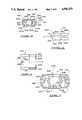
- FIG. 1is a perspective view of a preferred embodiment of the ocular treatment apparatus.
- FIG. 2is a sectional view taken along line 2--2 of FIG. 1.
- FIG. 3is a sectional view taken along line 2--2 of FIG. 1 illustrating the operation of the ocular treatment apparatus.
- FIG. 4is a sectional view taken along line 4--4 of FIG. 3.
- FIG. 5is a sectional view of an alternative embodiment of the ocular treatment apparatus.
- FIG. 6is a sectional view illustrating the operation of the apparatus shown in FIG. 5.
- FIG. 7is a sectional view taken along line 7--7 of FIG. 6.
- FIG. 8is a side plan view in partial cross-section of another ocular treatment apparatus embodying the invention shown placed over an eye.
- FIG. 9is a side plan view of the apparatus of FIG. 8 shown aligned over an eye and illustrating a partial cross-sectional view of the eyepiece portion.
- FIG. 10is a side plan view of the apparatus of FIG. 8 shown applying a drop of liquid medicament into an eye and also illustrating a partial cross-sectional view of the eyepiece portion.
- FIG. 11is a front plan view illustrating the eyepiece portion of the apparatus of FIG. 8.
- FIG. 12is a partial cross-sectional view of another ocular treatment apparatus embodying the present invention.
- FIG. 13is another partial cross-sectional view of the apparatus of FIG. 12, illustrating the operation of the apparatus in applying medicament to an eye.
- FIG. 14is a top end plan view of the inner casing of the apparatus of FIG. 12.
- FIG. 15is a top plan view of the inner casing of FIG. 14.
- FIG. 16is a side plan view of the inner casing of FIG. 14.
- FIG. 17is an enlarged, bottom end plan view of the inner casing of FIG. 14.
- FIG. 18is a bottom end plan view of the eyecup of the apparatus of FIG. 12.
- FIG. 19is a top plan view of the eyecup of FIG. 18.
- FIG. 20is a partial cross-sectional, side plan view of the eyecup of FIG. 18.
- FIG. 21is a top end plan view of the eyecup of FIG. 18.
- FIG. 22is an enlarged, bottom end plan view of the outer casing of the apparatus of FIG. 12.
- FIG. 23is a side plan view of the outer casing of FIG. 22.
- FIG. 24is an enlarged cross-sectional view of the outer casing of FIG. 23, taken along the line A--A.
- FIG. 25is a magnified cross-sectional view of the depresser mount of the outer casing of FIG. 22, taken along the line B--B.
- FIG. 26is a top plan view of the eyelid depresser of the apparatus of FIG. 12.
- FIG. 27is a side plan view of the eyelid depresser of FIG. 26.
- FIG. 28is a side plan view of the tamper-resistant ring of the apparatus of FIG. 12.
- FIG. 29is a top plan view of the tamper-resistant ring of FIG. 28.
- FIG. 30is an enlarged, partial cross-sectional view of the tamper-resistant ring of FIG. 29, taken along the line C--C.
- FIG. 31is a top plan view of the cover of the apparatus of FIG. 12.
- FIG. 32is a bottom end plan view of the cover of FIG. 31.
- FIG. 33is an enlarged cross-sectional view of the locking member for the cover of FIG. 32.
- FIG. 34is an enlarged cross-sectional view of the ocular vial of the apparatus of FIG. 12, illustrating on the left side the position of the ocular vial when medicament is released therefrom, and illustrating on the right side the position of the ocular vial when actuated to release medicament.
- Apparatus 10includes a tubular housing 11 constructed and arranged to receive and hold a dropper bottle 12. Housing 11 includes a front opening 13 which conforms to the facial area surrounding an eye 19. A sighting opening 14 is positioned in the tubular housing proximate to front opening 13 to properly orient an eyeball during use of the ocular treatment apparatus. A displacement mechanism, illustrated generally at 15, is included on housing 11 at a position generally diametrically opposite sighting opening 14. Displacement mechanism 15 retracts the lower eyelid to expose a surface of the eye below the pupil for application of medicament from reservoir 12.
- housing 11is constructed and arranged to retain a dropper bottle 12.
- the housingcan be modified to hold a dropper, single dose dropper vial, pressurized propellant device, or any other suitable applicator that stores and can deliver liquid medicament to the eye.
- housing 11includes a rear opening 16 shaped to receive dropper bottle 12.
- Housing 11includes a radially disposed collar 17 for receiving and releasably securing the neck of dropper bottle 12.
- Housing 11is configured so that the longitudinal axis of dropper bottle 12 is substantially parallel to and substantially aligned with the longitudinal axis of housing 11.
- Front opening 13is configured to nest in the facial area surrounding the eye socket. It is shaped so that apparatus 10 may be placed over the eye and easily maintained in a steady position with the tip of a dropper bottle nozzle 18 correctly positioned over eye 19. In this manner, when front opening 13 is positioned to surround the eye and a person tilts his head back, the drop of medicament falling from nozzle 18 will fall into the eye 19 by gravity.
- Displacement mechanism 15includes an engagement body 20 and drive member 21.
- Engagement body 20is a curved member which contacts lower eyelid 22 when front opening 13 is positioned around the eye.
- Engagement body 20is rotatably mounted to housing 11 at front opening 13 by axle 23. When curved engagement body 20 is caused to partially rotate, it everts lower eyelid 22 and exposes the cul-de-sac.
- the curved design of engagement body 20provides several important benefits.
- the area of contact between the curved surface of engagement body 20 and lower eyelid 22is considerable. This helps evert the eyelid properly and feels similar to using one's own finger to evert the eyelid.
- the wide engagement surfacealso makes exact placement of the engagement body 20 less critical.
- the curved surface of engagement body 20also prevents injuries which can occur when an instrument for sliding the eyelids back is utilized.
- front opening end 13is placed over the eye with engagement body 20 resting against lower eyelid 22.
- an elongated drive shaft 21is then displaced to partially rotate engagement body 20.
- a first end of drive shaft 21is pivotally connected to housing 11 by pivot pin 24.
- a second end of drive shaft 21is pivotally and slideably connected to engagement body 20 at slot 25, which is positioned around drive pin 26.
- Drive shaft 21includes a projection 27 intermediate its first and second ends.
- Housing 11defines a housing slot 28 through rear opening 16 aligned with projection 27 so that when drive shaft 21 is moved towards housing 11, projection 27 will pass through housing slot 28 to compress dropper bottle 12 and force drops 30 of liquid medicament from nozzle 18.
- the sides of slot 25push against drive pin 26 to partially rotate engagement body 20 to retract lower eyelid 22 coincident with liquid 30 being introduced to the eye from nozzle 18.
- Sighting opening 14is positioned proximate front open end 13 to correctly orient the eye and help uncover the cul-de-sac. It also helps control reflexive blinking which is often caused by the user sensing something approaching his exposed eye. Sighting opening 14 is provided in housing 11 near front opening 13 at a position diametrically opposed to curved engagement body 20, so that a user will have his eye steadied in an upwardly rotated position when his lower eyelid is everted. To properly uncover the cul-de-sac, sighting opening 14 should be positioned near front opening 13 so that the eye will be oriented upwardly though an angle A which should be at least 30°. However, in a preferred embodiment angle A is greater than 35°. Because the only light perceived by the user passes through sighting hole 14, a person having poor vision is assisted in properly orienting their eyeball.
- FIGS. 5 through 7a further embodiment of the ocular treatment apparatus, generally indicated as 45 is depicted, like reference numerals being utilized to depict like elements discussed above.
- This embodimenthas the same curved engagement body 20, front opening 13, sighting hole 14 and collar 17.
- Bottle 12rests in slidable seat 50.
- Seat 50can slide within outside tubular housing 51 and is upwardly biased by spring 33.
- Vertical drive shaft 32has two ends. Its first end is pivotally connected to slideable seat 50 by pin 52. The second end of vertical drive member 32 is slideably and pivotally connected to curved engagement body 20, by drive pin 53.
- a userplaces front opening 13 of apparatus 45 over the eye and contacts the lower eyelid with engagement body 20.
- the useragain peers through sighting opening 14.
- end 31 of dropper bottle 12is pushed into the housing, causing vertical drive member 32 to rotate curved engagement body 20.
- this further embodimentcauses the force necessary to evert the lower eyelid to be applied in a direction which will increase the contacting pressure between engagement body 20 and lower eyelid 22. This will decrease the chance of slippage to insure that lower eyelid 22 is everted.
- Spring 33returns the apparatus to its original position shown in FIG. 5.
- the ocular treatment apparatus of the instant inventionwhen used to apply liquid medicament to the eye, the above indicated advantages are observed.
- the dropper bottleis steadied over the eye in a correct orientation; the cul-de-sac of the conjunctiva is exposed by the combination of orienting the eyeball in an upwardly gazing position while everting the lower eyelid; involuntary blinking is prevented by the user focusing on light passing through the sighting opening at the same time that the lower eyelid is held in a depressed position. Therefore, drops of liquid medicament can be applied to the eye so that the medicament will flow to the cul-de-sac to increase the half life of its effectiveness.
- FIGS. 8 through 11another embodiment of the ocular treatment apparatus of the invention is illustrated generally as 110.
- the apparatus 110includes an inner housing 112 slideably engaged within an outer housing 114.
- the inner housing 112includes an eyepiece portion 120 and a substantially cylindrical portion 116 having an open end 118.
- the peripheral edge of the eyepiece portion 120defines an open end 122 shaped to conform to the contour of the facial tissue surrounding the eye.
- the eyepiece portion 120has defined in an upper wall thereof a sighting opening 124.
- the sighting opening 124is located near the open end 122 of the eyepiece and operates to help correctly orient the eye for uncovering the cul-de-sac in the same manner as the sighting opening 14 described above in relation to the previous embodiments.
- Sighting opening 124therefore, is similarly positioned so that the eye will be oriented upwardly through an angle A which is at least 30°.
- the inner housing 112 of apparatus 110defines an elongated channel 128 in an outer wall thereof extending in the axial direction of the apparatus.
- the end of channel 128 near the open end 118 of inner housing 112is shaped to form a seat 130 recessed in the channel 128 for a ball 132.
- the ball 132is preferably made of metal, such as steel.
- the apparatus 110is rotated and aligned over the eye, the ball 132 rolls from the recessed seat 130 and into the channel 128. In this manner, the ball 132 rolls down the channel 128 and hits the bottom wall thereof.
- the action of the ball striking the bottom wall of the channeltransmits vibrations through the wall of the apparatus 110 and into the facial tissue and bone structure of the person. In this way the person can feel or hear the falling ball and thus know when the apparatus is properly aligned over the eye. This is especially useful for persons that have poor eyesight or are deaf, since they can simply feel the vibrations of the rolling ball.
- the apparatus 110further includes a substantially cylindrical shaped vial 134 for containing liquid medicament.
- the vial 134is shaped to slideably fit within the cylindrical portion 116 of inner housing 112.
- the vialincludes a body 136 for holding liquid medicament, a neck 138, and a nozzle 140 for releasing drops of liquid.
- the body 136 of the vialis attached to the inner housing 116 in a known manner, such as by forming a snap fit.
- the body 116may be molded as a single piece with the inner housing 116.
- the shape of the nozzle 140is known, and may be the same as the nozzle 18 described above in relation to the previous embodiments.
- the body 136 of the vialdefines a cavity 142 therein coaxial with the apparatus 110 and extending along a substantial portion of the body 136. As can be seen, the closed end of cavity 142 is located near the opening of neck 138.
- the vial 138is formed of a flexible plastic material, and, as will be hereinafter described, the closed end of cavity 142 is pressed forward in order to release medicament into the eye.
- the outer housing 114 of apparatus 110is slideably engaged over inner housing 112 through an open end 144.
- Outer housing 114further defines a closed end 146 and a displacement member 148 projecting outwardly from closed end 146 and coaxial with the apparatus 110.
- a first lobe 150is formed in the outer Wall of inner housing 112
- a second lobe 152is formed on the inner wall of outer housing 114 below first lobe 150, to prevent outer housing 114 and inner housing 112 from sliding apart.
- the displacement member 148forces the closed end of cavity 142 forward in order to displace medicament into the eye.
- Third lobes 154, 154are preferably formed on the outer wall of inner housing 112 below first lobe 150, and second lobe 152, to limit the downward stroke of outer housing 114, and thus permit only a predetermined volume of medicament to be displaced through nozzle 140.
- the apparatus 110further includes a cushion member 156 formed of a flexible polymeric material.
- the cushion member 156includes on its free end a pad 158 having a generally curved shape to fit around the edge of eyepiece 120 and rest between the inner surface of eyepiece 120 and the facial tissue of the person, as best shown in FIGS. 8 through 10.
- eyepiece 120further defines an indentation 160 formed in a surface thereof and extending radially through the peripheral edge in an area diametrically opposed to sighting opening 124.
- the free end of pad 158is slideably fitted around the edge of eyepiece 120 and through indentation 160.
- the other end of pad 158is connected to one end of a flexible plastic bar 164 of the cushion member which, in turn, is connected on its other end to the edge of open end 144 of outer housing 114.
- the bar 164 of the cushion memberis attached to outer housing 114 in a known manner, such as ultrasonic welding.
- the cushion member 156is provided for safely and comfortably retracting downwardly the lower eyelid to permit medicament to flow to the interior cul-de-sac, and thus increase the comfort to the person and effectiveness of treatment.
- the free end of pad 158contacts the lower eyelid 22 when eyepiece 120 is positioned over the eye.
- the flexible bar 160presses the pad 158 against the indentation 160, and thus gently presses the pad downwardly to evert the lower eyelid 22 and expose the cul-de-sac, as illustrated in FIGS. 9 and 10.
- the flexible bar 164pushes outer housing 114 back toward its initial position and away from inner housing 112.
- eyepiece 120is placed over the eye so that it is conformably engaged with the facial tissue surrounding the eye, as shown in FIG. 8.
- the userlooks through sighting opening 124 to properly orient the eye and tilts his or her head back so that the apparatus 110 is rotated toward a vertical position, as shown in FIG. 9.
- the userknows that the apparatus has been rotated far enough when the ball 132 is displaced from its seat 130 and hits the bottom wall of channel 128.
- the userthen presses the outer housing 114 toward the eyepiece 120.
- the displacement member 148simultaneously forces the closed end of cavity 142 toward nozzle 140 and displaces a predetermined volume of medicament through nozzle 140 and into the eye, as shown in FIG. 10.
- the downward stroke of outer housing 114simultaneously causes the plastic bar 162 to press pad 158 against the indentation 160, and thus gently press the pad downwardly to evert the lower eyelid 22 and expose the cul-de-sac to receive the liquid or solid medicament.
- the medicament vial 134 of the apparatus 110can be an aerosol container that releases medicament under pressure and without the need for displacement member 148.
- FIGS. 12 and 13another ocular treatment apparatus embodying the present invention is indicated generally by the reference numeral 200.
- the apparatus 200comprises an inner casing 210, an ocular vial 212 (illustrated schematically) mounted within the inner casing 210, and an eyecup 214 mounted to one end of the inner casing 210.
- the apparatus 200further comprises an outer casing 216 mounted over the inner casing 210, and an eyelid depresser 218 coupled to the outer casing 216 and slideably mounted within the inner casing 210.
- a tamper-resistant ring 222is coupled to one end of the outer casing 216, and a coil spring 217 is mounted between the outer casing 216 and the ocular vial 212.
- a cover 220is removeably mounted over the eyecup 214, and coupled to the tamper-resistant ring 222, to cover the end of the apparatus 200.
- the various components of the apparatus 200are preferably made of polymeric materials suitable for pharmaceutical uses.
- the apparatus 200is used to release medicament from the vial 212 onto the exposed ocular cul-de-sac of an eye.
- the eyecup 214is placed over the facial tissue surrounding the eye, and the outer casing 216 is moved toward the inner casing 210, as indicated by the arrows in FIG. 13.
- the movement of the outer casing 216in turn pushes the eyelid depresser 218 downwardly.
- the eyelid depresser 218then gently engages the facial tissue below the eye, and thus displaces the lower eyelid so as to expose the ocular cul-de-sac.
- the movement of the outer casing 216also actuates the ocular vial 212 to release a drop of medicament once the ocular cul-de-sac is exposed.
- the inner casing 210defines a top wall 224, a bottom end 225, and an aperture 226 extending therethrough.
- the aperture 226is concentric with the longitudinal axis X of the inner casing 210, and is defined by a substantially cylindrical wall 228 extending between the top wall 224 and bottom end 225.
- Four indentations 230are formed within the cylindrical wall 228.
- the indentations 230are equally spaced apart from each other, and each projects radially outward from the X axis and extends along the axial length of the cylindrical wall 228.
- the cylindrical wall 228is dimensioned to receive the ocular vial 212, and the indentations 230 are adapted to position the ocular vial in place.
- the inner casing 210further defines two rectangular apertures 232, each extending through the top wall 224, and two indentations 233 extending into the edge of the bottom end 225, as shown in FIG. 15.
- the apertures 232 and indentations 233are dimensioned to permit the eyelid depresser 218 to slide therethrough, as will be described further below.
- the inner casing 210further defines two channels 234 extending therethrough between the top wall 224 and the bottom end 225. As shown in FIG. 14, each channel 234 spirals inwardly from the top wall 224 substantially toward the axial center of the casing 210. Each channel 234 is sloped downwardly with respect to the longitudinal axis X by about 40°, and is dimensioned to receive a steel ball 236, as shown in FIG. 14. Thus, when the ocular treatment apparatus 210 is rotated through an angle of about 40° with respect to a horizontal axis, as shown in FIG. 13, the steel balls 236 slide through the channels 234 and strike a bottom surface in the eyecup 214, as will be described further below.
- the inner casing 210further defines an outer wall 238, shaped to slideably fit within the outer casing 216.
- the outer wall 238defines four channels 240 extending along each of its four corners. The channels 240 are provided to facilitate the sliding movement of the outer casing 216 over the inner casing 210.
- the inner casing 210further defines four finger slots 242 extending through the top wall 224. Each finger slot 242 is defined by an end wall 244. Each end wall 244 is sloped with respect to the longitudinal axis X of the inner casing 210 by an angle B, as shown in FIG. 16. The angle B is preferably about 45°.
- the eyecup 214defines a peripheral edge 248 shaped to conformably engage the facial tissue covering the bone structure surrounding an eye.
- a dome-shaped wall 250extends upwardly from the edge 248 to block the passage of light into a user's eye.
- the eyecup 214further defines a substantially cylindrical opening 252 extending therethrough.
- the opening 252is defined by a substantially cylindrical inner wall 254, concentric with the longitudinal axis X.
- a pair of substantially square notches 256are formed within the cylindrical wall 254.
- the notches 256are diametrically opposed to each other and extend along the cylindrical inner wall 254 in the axial direction X.
- the inner wall 254 and notches 256are dimensioned to receive a locking member on the cover 220, as will be described further below.
- a sighting opening 258extends through the wall 250.
- the sighting opening 258is positioned to permit light to pass therethrough.
- the eyecup 214is placed over an eye and the user looks at the opening 258, the eye is oriented upwardly.
- the medicament dispensed from the ocular vial 212is permitted to fall into the exposed ocular cul-de-sac of the eye, as shown in FIG. 13.
- the eyecup 214further defines an outer wall 260 extending upwardly from the edge 248 and spaced apart from the dome-shaped wall 250, as shown in FIG. 21.
- a substantially flat indentation 262is formed along one side of the wall 260. The indentation 262 is dimensioned to permit the eyelid depresser 218 to slide therethrough.
- the eyecup 214further defines a flange 264 extending upwardly from the dome-shaped wall 250, and surrounding the inner cylindrical wall 254.
- the flange 264defines a substantially cylindrical outer wall 266.
- Two substantially square mounting tabs 268project radially outward from the outer wall 266.
- the mounting tabs 268are dimensioned to be received within two corresponding indentations 230 on the inner casing 210, to position the eyecup 214 with respect to the inner casing.
- a mounting notch 270is formed within the base of the outer wall 266, as shown in FIG. 20, to mount the inner casing 210 to the eyecup 214.
- the inner casing 210defines a chamfered tab 272 on the inside surface of its bottom end 225, which projects into the aperture 226, as shown in FIG. 17.
- the eyecup 214is mounted to the inner casing 210 by inserting the flange 264 into the cylindrical wall 228, so that the mounting tabs 268 are inserted into the corresponding notches 230.
- the chamfered tab 272is in turn pushed over the cylindrical wall 266 and snapped into the mounting notch 270, thus securing the eyecup 214 to the inner casing 210, as shown in FIG. 12.
- the eyecup 214further defines two bayonnet mounts 274 within the flange 264, as shown in FIG. 21. Each bayonnet mount 274 is located at the top end of a respective notch 256, to lock the cover 220 to the eyecup 214, as will be described further below.
- a pair of ribs 276extend inwardly from the inside surface of the wall 260 on diametrically opposite sides of the flange 264. The ribs 276 are positioned so that when the eyecup 214 is mounted to the inner casing 210, each rib 276 is located immediately below a respective channel 234. Therefore, when the steel balls 236 slide through the channels 234, each ball strikes a respective rib 276. The steel balls 236 thus impart vibrations through the edge 248 of the eyecup into the facial tissue and bone structure surrounding the eye.
- the eyecup 214further defines a pair of depresser guides 278 projecting upwardly from the domed surface 250 on either side of the flange 264. As shown in FIG. 20, each depresser guide 276 defines a guide surface 278, which has a slight radius of curvature R. The radius of curvature R is dimensioned so that the guide surfaces 278 direct the eyelid depresser 218 downwardly toward the facial tissue below the eye, as will be described further below.
- the outer casing 216defines a closed end 280, an open end 282, and an outer wall 284.
- the outer wall 284defines two gripping portions 286 located on opposite sides of the outer casing 216.
- Each gripping portion 286slopes upwardly relative to the longitudinal axis X in the direction from the closed end 280 to the open end 282.
- the gripping portions 286provide a convenient surface for a user to grip the outer casing 216 and slide the outer casing relative to the inner casing 210, as will be described further below.
- the outer casing 216further comprises four fingers 288 projecting inwardly from the inside surface of the closed end 280, as shown in FIGS. 22 and 24.
- the four fingers 288are equally spaced relative to each other about the longitudinal axis X of the apparatus.
- each finger 288defines a chamfered tip 290.
- a vial tab 292is located immediately above each tip 290 and projects inwardly toward the longitudinal axis X.
- the vial tabs 292are thus adapted to engage the ocular vial 212 by sliding the outer casing 216 toward the eyecup 214.
- the fingers 288in turn depress the vial 212 to actuate the vial to release medicament, as will be described further below.
- the outer casing 216further defines a lip 294 extending along the outer surface of its open end 282.
- the lip 294is dimensioned to snap into the tamper-resistant ring 222, as will be described further below.
- the outer casing 216further comprises two depresser mounts 296 projecting inwardly from the inside surface of the closed end 280.
- a typical depresser mount 296is illustrated in further detail in FIG. 25.
- Each depresser mount 296defines an aperture 298 extending through the free end thereof, and a lip 300 extending around the aperture 298.
- the apertures 298are dimensioned to receive the free ends of the eyelid depresser 218, to couple the eyelid depresser to the outer casing 216, as will be described further below.
- the eyelid depresser 218comprises a crossbar 302 and two legs 304 projecting outwardly from either end of the crossbar 302.
- the two legs 304extend in the axial direction X of the apparatus 200 in a parallel relationship to each other. As shown in FIG. 27, each leg 304 is curved downwardly toward the crossbar 302.
- a depresser tab 306projects outwardly from the middle of the crossbar 302 in the opposite direction of the legs 304.
- the depresser tab 306defines a substantially hemispherical outer surface 308, which is adapted to engage the facial tissue below an eye.
- the depresser tab 306is made of a flexible polymeric material so that it can flex inwardly upon engaging the facial tissue below an eye, as shown in FIG. 13.
- a face cushion(not shown) made of a sponge-like polymeric material, can be placed over the depresser tab 306 to facilitate gently displacing the facial tissue below an eye.
- Each leg 304defines an indentation 312 adjacent to its free end.
- Each indentation 312is dimensioned to receive therein a lip 300 of a respective depresser mount 296 on the outer casing 216.
- the eyelid depresser 218further comprises a pair of guide strips 314, each strip projecting outwardly from the free end of a respective leg 304.
- the guide strips 314are provided to guide the free ends of the legs 304 into the apertures 298 of the depresser mounts 296.
- the eyelid depresser 218is coupled to the outer casing 216 by sliding the guide strips 314 into the respective apertures 298.
- each depresser mount 296is then pressed through the apertures 298, so that the lip 300 on each depresser mount 296 is secured within the respective indentation 312 of each leg 304, as shown in FIG. 13.
- the legs 304are coupled to the depresser mounts 296 and slideably mounted through the rectangular apertures 232 and indentations 233 of the inner casing 210.
- the ring 222comprises a bottom wall 316 shaped to correspond to the open end 282 of the outer casing 216. As shown in FIG. 30, a top wall 318 projects upwardly from the bottom wall 316 and defines a lip 320 projecting inwardly therefrom. The lip 320 is dimensioned to retain the lip 294 on the open end of the outer casing 216.
- the outer casing 216is coupled to the tamper-resistant ring 222 by pressing its open end 282 into the ring 222, so that the lip 294 snaps into the space below the lip 320, as shown in FIG. 12.
- the tamper-resistant ring 222further comprises four tabs 322 spaced apart from each other and projecting inwardly from the bottom wall 316.
- the bottom wall 316defines an outer surface 324, which is sloped inwardly by an angle C relative to the longitudinal axis X of the apparatus.
- the angle Cis preferably about 30°.
- a cover ring 326projects outwardly from the sloped surface 324, and is connected to the surface 324 by an annular breakable section 328.
- the breakable section 328has a relatively slight cross-sectional thickness so that the cover ring 326 can be easily snapped away from the sloped surface 324, as will be described further below.
- the cover 220defines a closed end 330, an open end 332, and an outer wall 334 extending therebetween.
- the outer wall 334is shaped to fit over the outer wall 260 of the eyecup 214.
- the cover ring 326 of the tamper-resistant ring 222further defines a first welding lip 336, which is shaped to correspond to a second welding lip 337 formed on the open end 332 of the cover 220.
- the open end 332 of the cover 220is fastened to the ring 222, as shown in FIGS. 12 and 30, in a manner known to those skilled in the art, such as by ultrasonic welding, or heat welding.
- the cover 220is welded to the tamper-resistant ring 222 after a vial 212 of medicament is inserted within the apparatus 200, and the apparatus is ready to be shipped by the manufacturer, such as a pharmaceutical company.
- the cover 220cannot then be removed from the apparatus 200, unless the tamper-resistant ring 222 is fractured through the breakable section 328.
- the section 328is fractured by holding the outer casing 216 and striking the bottom of the cover 220 against a firm surface.
- the open end 282 of the outer casing 216is thus forced down against the four tabs 322.
- the force against the tabs 322is transmitted by the sloped surface 324 against the cover ring 326 which, in turn, causes the breakable section 328 to fracture.
- the cover 220further includes an aperture 338 defined by a substantially cylindrical surface 340.
- the cylindrical surface 340extends through the top wall 330 and is concentric with the longitudinal axis X.
- the cylindrical surface 340defines therein a pair of notches 342 projecting radially outward from the axial center of the cover 220, and diametrically opposed to each other.
- the cylindrical surface 340 and notches 342are dimensioned to receive a locking member, indicated generally as 344 in FIG. 33.
- the locking member 344comprises a flange 346 and a hollow stem 348 projecting outwardly therefrom.
- the stem 348defines on the free end thereof a pair of mounting bayonnets 350.
- the bayonnets 350are diametrically opposed to each other, and project outwardly in a direction substantially perpendicular to the longitudinal axis X.
- the bayonnets 350are dimensioned to be received within the notches 256 and rotatably locked into the bayonnet mounts 274 of the eyecup 214.
- a pair of mounting tabs 352project outwardly from the stem 348, and are spaced immediately below the bottom surface of the flange 346.
- the tabs 352are dimensioned to fit through the notches 342 in the top wall 330 of the cover 220.
- the locking member 344is thus inserted through the aperture 338.
- the flange 346is then rotated so that the tabs 352 prevent the locking member from being removed therefrom.
- the free end of the stem 348is positioned below the open end 330 of the cover 220. Therefore, if the cover 220 is removed from the apparatus 200 and accidentally dropped, the stem 330 will likely not contact the ground or other contaminated surfaces.
- the cover 220is locked to the eyecup 214 by sliding the bayonnets 350 through the notches 256 in the eyecup. Then, once the bayonnets are inserted into the bayonnet mounts 274, the flange 346 is rotated, so that the bayonnets 350 are locked into the bayonnet mounts 274. Therefore, once the locking member 344 is locked in place, a child has to simultaneously rotate the flange 346 and pull the cover away from the eyecup 214 to release the cover. As shown in FIG. 12, the locking member 348 is seated over the opening for the ocular vial 212 in the eyecup 214. Therefore, the locking member 348 and cover 220 prevent contaminating particles from contacting the ocular vial 212.
- the ocular vial 212is filled with medicament by a pharmaceutical company in a sterile environment.
- the ocular vial 212is then covered with a cap 353, as shown in FIG. 12. Once the ocular vial 212 is covered with the cap 353, it can then be removed from the sterile environment without contaminating the medicament.
- the ocular vial 212is then inserted into the inner casing 210.
- the cap 353is dimensioned to be pressed into the hollow stem 348, as shown in FIG. 12. Therefore, when the ocular vial 212 is inserted into the inner casing 210, the cap 353 is pressed into the stem 348, as shown in FIG. 12. Then, when the cover 220 is removed by the user, the cap 353 is removed with the cover inside the stem 348.
- the ocular vial 212comprises a rigid outer body 354 and a rigid inner body 356 slideably mounted within the outer body 354.
- the outer body 354defines an open end 358, a closed end 360, and an outer wall 362 extending therebetween.
- the outer wall 362defines a substantially cylindrical surface 363 dimensioned to be received within the cylindrical wall 228 of the inner casing 210.
- a pair of mounting nubs 364project outwardly from the cylindrical surface 363 in a direction substantially perpendicular to the longitudinal axis X.
- the mounting nubs 364are diametrically opposed to each other and dimensioned to fit within two corresponding indentations 230 in the inner casing 210.
- the ocular vial 212is thus mounted within the inner casing 210 by inserting the closed end 360 into the aperture 226 and cylindrical wall 228.
- the ocular vial 212is positioned within the cylindrical wall 228, so that the mounting nubs 364 are inserted within the corresponding indentations 230.
- the ocular vial 212is then pushed inwardly until its closed end 360 is seated against the flange 264 of the eyecup 214. As shown in FIG. 12, because the closed end 360 of the ocular vial 212 is located within the eyecup 214, it is protected from contact with contaminated surfaces.
- the outer body 354 of the ocular vial 212further defines a nozzle orifice 366 extending through the closed end 360 concentric with the longitudinal axis X.
- a first valve seat 367extends around the nozzle orifice 366 on the inside surface of the closed end 360.
- a cylindrical wall 368projects upwardly from the inside surface of the closed end 360, and defines a valve chamber 370 extending therethrough.
- the valve chamber 370is oriented along the longitudinal axis X and is in fluid communication with the nozzle orifice 366.
- a valve 372is seated within the valve chamber 370.
- the valve 372includes a top lobe 373, a bottom lobe 375, and two flexible members 377 extending therebetween.
- the valve 372further defines several grooves 379 extending along the outer surface of the bottom lobe 375.
- the bottom lobe 375is dimensioned to be seated within the first valve seat 367 to cover the nozzle orifice 366.
- the grooves 379are in turn provided to allow medicament to flow therethrough and thus through the nozzle orifice 366 for release into an eye, as will be described further below.
- the inner body 356defines an open end 374, a closed end 376, and an outer wall 378 extending therebetween.
- the outer wall 378is dimensioned to be slideably received within the outer wall 363 of the outer body 354, as shown in FIG. 34.
- the outer wall 378thus defines a reservoir 380 for holding medicament.
- the inner body 356further defines an orifice 382 extending through the closed end 376, concentric with the longitudinal axis X.
- a flange 384projects upwardly from the closed end 376 and surrounds the orifice 382.
- the flange 384defines a cylindrical surface 386 spaced away from, and extending around the orifice 382, thus defining a drop cavity 388 therein.
- the ocular vial 212further comprises a shaft 390 defining a cylindrical head 392 on one end thereof.
- the other end of the shaft 390is inserted through the orifice 382, and threadedly engaged within the free end of the cylindrical wall 368 of the outer body 354.
- the inner body 356can slide within the outer body 354 along the shaft 390, between the head 392 and the free end of the cylindrical wall 368.
- the shaft 390further defines a first orifice 394 extending through a side wall thereof immediately below the head 392.
- a second orifice 396extends through the free end of the shaft 390, concentric with the longitudinal axis X.
- the free end of the shaft 390further defines a second valve seat 398 surrounding the second orifice 396.
- the second valve seat 398is shaped to seat the top lobe 373 of the valve 372.
- the shaft 390further defines a channel 400 extending between the first orifice 394 and the second orifice 396, to permit medicament to flow therethrough.
- the ocular vial 212further comprises a coil spring 402, illustrated schematically.
- the coil spring 402is seated between the closed end 376 of the inner body 356, and the inside surface of the closed end 360 of the outer body 354.
- the inner body 354is normally spring biased against the head 392, as shown on the left side of FIG. 34.
- the ocular vial 212further comprises a cap 404 inserted into the open end 374 of the inner body 356.
- the cap 404is shaped so that the medicament within the chamber 380 does not leak between the cap and the outer wall 378. When medicament is dispensed from the chamber 380, the cap 404 slides downwardly under the suction forces within the chamber 380, and is thus maintained in close proximity with the medicament.
- the ocular vial 212further comprises a lid 406 mounted over the open end 374 of the inner body 356.
- the lid 406defines an aperture 408 extending through a top wall thereof.
- the aperture 408is provided to permit airflow therethrough when the cap 404 slides downwardly under the suction forces within the chamber 380.
- the lid 406is dimensioned so that its top edge abuts against the vial tabs 292 on the fingers 288 of the outer casing 216.
- the vial tabs 292are thus used to push the inner body 356 inwardly to actuate the vial 212, as will be described below.
- the inner body 356further defines a notch 410 within the outside surface of the outer wall 378.
- the notch 410is located immediately below the cap 406 and extends along the periphery of the outer wall 378.
- the notch 410is provided to allow air to pass therethrough when depressing the inner body 356 within the outer body 354.
- the ocular vial 212is actuated to release medicament by pushing the inner body 356 toward the outer body 354, against the spring 402, as shown on the right side of FIG. 34. Medicament in the reservoir 380 is then permitted to flow into the drop cavity 388 and in turn into the channel 400.
- the spring 402pushes the inner body 356 upwardly into its initial position, as shown on the left side of FIG. 34.
- the cylindrical surface 386is thus pushed over the head 392, so that the medicament within the drop cavity 388 is pressurized and thus forced through the first orifice 394 and into the channel 400.
- the pressurized medicament in the channel 400flows into the second orifice 396 and over the top lobe 373 of the valve 372.
- the pressure of the medicamentcauses the flexible members 377 to flex outwardly, as shown in FIG. 34, so that the top lobe 373 moves down and away from the second orifice 396.
- the pressurized medicamentis permitted to flow into the valve chamber 370.
- the pressurized medicamentin turn flows through the grooves 379 in the bottom lobe 375 and into the nozzle orifice 366.
- a pressurized discharge of medicamentis released through the nozzle orifice 366 and into the everted cul-de-sac.
- the pressurized dischargeis particularly suitable for use in low gravity environments, where gravity cannot be used to cause a drop of medicament to fall into the eye.
- the drop cavity 388is dimensioned so that an exact amount of medicament is released each time the ocular vial 212 is actuated. Once the pressurized medicament is released, the top lobe 373 is moved upwardly by the flexible members 377 and into the second valve seat 398. The valve 372 thus prevents air or other impurities from entering the channel 400 that might contaminate the medicament in the chamber 380.
- a userremoves the cover 220 and places the edge 248 of the eyecup 214 on the facial tissue surrounding the eye, as shown in FIG. 13. The user then tilts his or her head back, and rotates the apparatus 200 upwardly over the eye, while simultaneously looking toward the sighting opening 258. Then, when the user feels the vibrations of the steel balls 236 striking the eyecup 214, the apparatus 200 is properly positioned to release medicament into the eye.
- the medicament within the vial 212is released by pushing the outer casing 216 over the inner casing 210.
- the sliding movement of the outer casing 216simultaneously pushes the eyelid depresser 218 through the apertures 232 and indentations 233 in the inner casing 210.
- the eyelid depresser 218is in turn deflected downwardly over the guide surfaces 278 of the depresser guides 276.
- the depresser tab 308thus gently engages the facial tissue below the eye, and in turn displaces the facial tissue downwardly, as the outer casing 216 is further depressed.
- the displaced facial tissuein turn displaces the lower eyelid, so as to expose the ocular cul-de-sac to receive a drop of medicament, as shown in FIG. 13.
- the fingers 288engage the lid 406 on the ocular vial 212.
- the tips 290 of the fingersare forced over the edge of the lid 406.
- the vial tabs 292engage the lid 406 and, in turn, push the inner body 356 toward the outer body 354.
- the tips 290 of the fingers 288engage the sloped surfaces 244 on the inner casing 210.
- the tips 290are then forced outwardly along the sloped surfaces 244.
- the vial tabs 292are therefore also forced outwardly away from the lid 406 of the ocular vial 212.
- the spring 402drives the inner body 356 upwardly, as shown on the left side of FIG. 34.
- the medicamentis then released through the orifice 366, into the exposed ocular cul-de-sac of the eye.
- One advantage of the present inventionis that by displacing the lower eyelid and exposing the ocular cul-de-sac, the medicament is released onto the exposed cul-de-sac and, as a result, the effectiveness of the medicament is maximized.
- the ocular cul-de-sacis both a relatively low sensitivity area, and a low tear turnover area of the eye.
- the eyenormally blinks with the upper eyelid to place tears over the cornea. Therefore, by placing medicament in the ocular cul-de-sac, a blinking reaction by the patient is minimized. However, if the patient does blink, the blinking likely will not substantially displace the medicament beneath the lower eyelid. Therefore, by employing the apparatus of the present invention, the medicament is not easily diluted and its residence time within the eye is increased so as to maximize its effectiveness.
- the userremoves the apparatus 200 away from the eye.
- the spring 217pushes the outer casing 216 away from the inner casing 210, back into its initial position, as shown in FIG. 12.
- the outer casing 216simultaneously carries the eyelid depresser 218 back through the inner casing 210.
- the apparatus 200can then be used to release another drop of medicament, in the same way as described above.
Landscapes
- Health & Medical Sciences (AREA)
- Ophthalmology & Optometry (AREA)
- Engineering & Computer Science (AREA)
- Biomedical Technology (AREA)
- Heart & Thoracic Surgery (AREA)
- Vascular Medicine (AREA)
- Life Sciences & Earth Sciences (AREA)
- Animal Behavior & Ethology (AREA)
- General Health & Medical Sciences (AREA)
- Public Health (AREA)
- Veterinary Medicine (AREA)
- Medical Preparation Storing Or Oral Administration Devices (AREA)
Abstract
Description
Claims (37)
Priority Applications (12)
| Application Number | Priority Date | Filing Date | Title |
|---|---|---|---|
| US07/452,782US4981479A (en) | 1987-11-06 | 1989-12-19 | Ocular treatment apparatus |
| CA002031960ACA2031960C (en) | 1989-12-19 | 1990-12-11 | Ocular treatment apparatus |
| NO905357ANO179477C (en) | 1989-12-19 | 1990-12-12 | Apparatus for transferring a drug to an eye |
| AU67984/90AAU627418B2 (en) | 1989-12-19 | 1990-12-12 | Ocular treatment apparatus |
| ES90313789TES2060969T3 (en) | 1989-12-19 | 1990-12-17 | EYE TREATMENT APPARATUS. |
| EP90313789AEP0437953B1 (en) | 1989-12-19 | 1990-12-17 | Ocular treatment apparatus |
| DK90313789.1TDK0437953T3 (en) | 1989-12-19 | 1990-12-17 | Eye treatment apparatus |
| DE69012304TDE69012304T2 (en) | 1989-12-19 | 1990-12-17 | Eye treatment facility. |
| JP02417895AJP3113289B2 (en) | 1989-12-19 | 1990-12-19 | Eye treatment device |
| KR1019900021255AKR0168838B1 (en) | 1989-12-19 | 1990-12-19 | Ocular Therapy |
| US07/635,300US5133702A (en) | 1987-11-06 | 1990-12-28 | Ocular treatment apparatus |
| SG14495ASG14495G (en) | 1989-12-19 | 1995-01-26 | Ocular treatment apparatus |
Applications Claiming Priority (3)
| Application Number | Priority Date | Filing Date | Title |
|---|---|---|---|
| US07/118,388US4792334A (en) | 1987-11-06 | 1987-11-06 | Occular treatment apparatus |
| US07/267,526US4946452A (en) | 1987-11-06 | 1988-11-04 | Ocular treatment apparatus |
| US07/452,782US4981479A (en) | 1987-11-06 | 1989-12-19 | Ocular treatment apparatus |
Related Parent Applications (1)
| Application Number | Title | Priority Date | Filing Date |
|---|---|---|---|
| US07/267,526Continuation-In-PartUS4946452A (en) | 1987-11-06 | 1988-11-04 | Ocular treatment apparatus |
Related Child Applications (1)
| Application Number | Title | Priority Date | Filing Date |
|---|---|---|---|
| US07/635,300ContinuationUS5133702A (en) | 1987-11-06 | 1990-12-28 | Ocular treatment apparatus |
Publications (1)
| Publication Number | Publication Date |
|---|---|
| US4981479Atrue US4981479A (en) | 1991-01-01 |
Family
ID=27382156
Family Applications (1)
| Application Number | Title | Priority Date | Filing Date |
|---|---|---|---|
| US07/452,782Expired - LifetimeUS4981479A (en) | 1987-11-06 | 1989-12-19 | Ocular treatment apparatus |
Country Status (1)
| Country | Link |
|---|---|
| US (1) | US4981479A (en) |
Cited By (73)
| Publication number | Priority date | Publication date | Assignee | Title |
|---|---|---|---|---|
| US5133702A (en)* | 1987-11-06 | 1992-07-28 | O.P.T.I.C. | Ocular treatment apparatus |
| US5154710A (en)* | 1988-06-09 | 1992-10-13 | Williams John L | Ophthalmic device |
| WO1993019806A1 (en) | 1992-04-06 | 1993-10-14 | Self-Instill & Co., Inc. | Cartridge for applying medicament to an eye from a dispenser |
| EP0615460A4 (en)* | 1991-12-02 | 1994-12-07 | Py Daniel C | Apparatus for applying medicament to an eye. |
| US5401259A (en)* | 1992-04-06 | 1995-03-28 | Py Daniel C | Cartridge for applying medicament to an eye |
| US5411175A (en)* | 1993-03-08 | 1995-05-02 | New England Pharmaceuticals, Inc. | Cartridges, devices and methods for dispensing liquids |
| USD370257S (en) | 1995-01-09 | 1996-05-28 | Christopher Warren S | Ocular solution applicator |
| US5762606A (en)* | 1997-05-16 | 1998-06-09 | Minnich; Thomas E. | Combined eyelid retractor and eye flushing device |
| US5810794A (en)* | 1996-11-21 | 1998-09-22 | Peplinski; Lee S. | Eye drop dispensing device |
| US5855322A (en)* | 1997-09-10 | 1999-01-05 | Py; Daniel | System and method for one-way spray aerosol tip |
| US6033384A (en)* | 1997-12-18 | 2000-03-07 | Py; Daniel | One-way actuation release mechanism for a system for applying medicament |
| US6254579B1 (en) | 1999-11-08 | 2001-07-03 | Allergan Sales, Inc. | Multiple precision dose, preservative-free medication delivery system |
| US6302101B1 (en) | 1999-12-14 | 2001-10-16 | Daniel Py | System and method for application of medicament into the nasal passage |
| US6506183B2 (en) | 2001-02-02 | 2003-01-14 | Advanced Medical Optics | One shot actuation housing apparatus for instilling a medication into an eye |
| US6524287B1 (en) | 2000-10-10 | 2003-02-25 | Advanced Medical Optics | Housing apparatus with rear activated return button for instilling a medication into an eye |
| US6533764B1 (en) | 2000-11-06 | 2003-03-18 | Allergan, Inc. | Twist housing apparatus for instilling a medication into an eye |
| US20040078010A1 (en)* | 2000-10-16 | 2004-04-22 | Tom Ahlstrom | Eye rinsing device |
| US6739636B2 (en) | 2001-05-02 | 2004-05-25 | Medical Instill Technologies, Inc. | Contact lens applicator and cartridge used in connection therewith |
| USD492192S1 (en) | 2001-10-23 | 2004-06-29 | Medical Instill Technologies, Inc. | Dispenser |
| US6761286B2 (en) | 2000-10-23 | 2004-07-13 | Medical Instill Technologies, Inc. | Fluid dispenser having a housing and flexible inner bladder |
| USD495946S1 (en) | 2001-10-23 | 2004-09-14 | Medical Instill Technologies, Inc. | Dispenser |
| US20040256487A1 (en)* | 2003-05-20 | 2004-12-23 | Collins James F. | Ophthalmic drug delivery system |
| USD501498S1 (en) | 2002-05-02 | 2005-02-01 | Medical Instill Technologies, Inc. | Automatic contact lens applicator |
| US20050029307A1 (en)* | 2000-10-23 | 2005-02-10 | Daniel Py | Ophthalmic dispenser and associated method |
| US20050089358A1 (en)* | 2003-07-17 | 2005-04-28 | Daniel Py | Piston-type dispenser with one-way valve for storing and dispensing metered amounts of substances |
| US20050127693A1 (en)* | 2003-11-17 | 2005-06-16 | Daniel Py | Contact lens transfer device and associated method |
| USD507752S1 (en) | 2002-10-21 | 2005-07-26 | Medical Instill Technologies, Inc. | Dispenser |
| US20050189379A1 (en)* | 2004-01-27 | 2005-09-01 | Daniel Py | Dispenser having variable-volume storage chamber and depressible one-way valve assembly for dispensing creams and other substances |
| US20050261640A1 (en)* | 2000-10-16 | 2005-11-24 | Tom Ahlstrom | Easily carried eye rinsing device |
| US20060017297A1 (en)* | 2001-05-02 | 2006-01-26 | Daniel Py | Apparatus for applying and removing contact lenses and related method |
| US20060021617A1 (en)* | 2000-07-14 | 2006-02-02 | Hoffman Andrew M | Drug delivery device for animals |
| USD516721S1 (en) | 2003-01-28 | 2006-03-07 | Medical Instill Technologies, Inc. | Dispenser |
| USD516604S1 (en) | 2002-11-06 | 2006-03-07 | Medical Instill Technologies, Inc. | Automatic contact lens applicator |
| US20060065677A1 (en)* | 2004-09-27 | 2006-03-30 | Daniel Py | Laterally-actuated dispenser with one-way valve for storing and dispensing metered amounts of substances |
| US20060092678A1 (en)* | 2004-11-02 | 2006-05-04 | Nec Electronics Corporation | Apparatus and method for power conversion |
| USD521045S1 (en) | 2002-11-06 | 2006-05-16 | Daniel Py | Automatic contact lens applicator |
| USD521638S1 (en) | 2003-11-14 | 2006-05-23 | Medical Instill Technologies, Inc. | Ophthalmic delivery device |
| USD521639S1 (en) | 2003-11-14 | 2006-05-23 | Medical Instill Technologies, Inc. | Ophthalmic delivery device |
| USD529941S1 (en) | 2002-11-06 | 2006-10-10 | Medical Instill Technologies, Inc. | Automatic contact lens applicator |
| US20070119969A1 (en)* | 2003-05-20 | 2007-05-31 | Optimyst Systems Inc. | Ophthalmic fluid reservoir assembly for use with an ophthalmic fluid delivery device |
| US20070194045A1 (en)* | 2004-12-04 | 2007-08-23 | Daniel Py | One-way valve and apparatus and method of using the valve |
| US20080078781A1 (en)* | 2006-09-08 | 2008-04-03 | Daniel Py | Method for dispensing fluids |
| US20080118299A1 (en)* | 2006-11-11 | 2008-05-22 | Daniel Py | Multiple Dose Delivery Device with Manually Depressible Actuator and One-Way Valve for Storing and Dispensing Substances, and Related Method |
| US20080121668A1 (en)* | 2002-08-13 | 2008-05-29 | Daniel Py | Device with Chamber and First and Second Valves in Communication Therewith, and Related Method |
| US20080135130A1 (en)* | 2005-08-01 | 2008-06-12 | Daniel Py | Dispenser with Sealed Chamber, One-Way Valve and Needle Penetrable and Laser Resealable Stopper |
| US20080142112A1 (en)* | 2003-05-12 | 2008-06-19 | Daniel Py | Dispenser and Apparatus and Method of Filling a Dispenser |
| US20080149191A1 (en)* | 2004-12-04 | 2008-06-26 | Daniel Py | Method of Using One-Way Valve and Related Apparatus |
| US20090212133A1 (en)* | 2008-01-25 | 2009-08-27 | Collins Jr James F | Ophthalmic fluid delivery device and method of operation |
| US20090281508A1 (en)* | 2008-05-07 | 2009-11-12 | Joseph Alvino | Combination eye cup and drop dispenser |
| US20100022971A1 (en)* | 2008-02-05 | 2010-01-28 | Marx Alvin J | Precision lid retracting eyedropper device |
| US20100174247A1 (en)* | 2006-08-11 | 2010-07-08 | Teika Pharmaceutical Co., Ltd. | Eye drops container |
| US20100286634A1 (en)* | 2008-02-05 | 2010-11-11 | Marx Alvin J | Automated Eyedrop Delivery System with Eyelid Retracting Legs |
| US20100286633A1 (en)* | 2008-02-05 | 2010-11-11 | Marx Alvin J | Precision Lid Retracting Eyedropper Device |
| EP2510911A1 (en)* | 2011-04-13 | 2012-10-17 | Sanofi-Aventis Deutschland GmbH | Apparatus for intraocular injection |
| US20120310184A1 (en)* | 2010-01-22 | 2012-12-06 | First Aid Company Aps | Handheld apparatus for eye-washing |
| US8376189B2 (en) | 2010-05-07 | 2013-02-19 | Alps Llc | Dispensing machine valve and method |
| US8684980B2 (en) | 2010-07-15 | 2014-04-01 | Corinthian Ophthalmic, Inc. | Drop generating device |
| US8733935B2 (en) | 2010-07-15 | 2014-05-27 | Corinthian Ophthalmic, Inc. | Method and system for performing remote treatment and monitoring |
| EP2645971B1 (en)* | 2010-11-29 | 2014-12-17 | Sanofi-Aventis Deutschland GmbH | Medicated module for an ophthalmic drug delivery device |
| US9072581B1 (en) | 2014-09-25 | 2015-07-07 | King Saud University | Eye dropper positioning and guiding apparatus |
| US9087145B2 (en) | 2010-07-15 | 2015-07-21 | Eyenovia, Inc. | Ophthalmic drug delivery |
| WO2016015678A1 (en)* | 2014-08-01 | 2016-02-04 | 曹灵欢 | Assistant device for eye drops |
| US10154923B2 (en) | 2010-07-15 | 2018-12-18 | Eyenovia, Inc. | Drop generating device |
| FR3077483A1 (en)* | 2018-02-06 | 2019-08-09 | Nemera La Verpilliere | DEVICE FOR ASSISTING THE USE OF A DEVICE FOR DISPENSING A LIQUID PRODUCT |
| USD865942S1 (en)* | 2015-07-31 | 2019-11-05 | Bedo Solutions, Llc | Alignment sleeve for eye-drop bottle |
| JP2020063073A (en)* | 2018-10-17 | 2020-04-23 | 花王株式会社 | Liquid agent discharge container |
| US10639194B2 (en) | 2011-12-12 | 2020-05-05 | Eyenovia, Inc. | High modulus polymeric ejector mechanism, ejector device, and methods of use |
| US20210161707A1 (en)* | 2018-08-10 | 2021-06-03 | Azura Ophthalmics Ltd. | Dispenser for precise extraction of a semi-solid product |
| US20220233350A1 (en)* | 2019-04-14 | 2022-07-28 | Marcus Van Gorden | Ocular medication delivery apparatus |
| US20220388737A1 (en)* | 2019-11-05 | 2022-12-08 | Alejandro GAMBOA BURGOS | Kit for ophthalmic solutions in screw-cap dropper bottles |
| US20230100638A1 (en)* | 2021-02-05 | 2023-03-30 | Shenzhen Institutes Of Advanced Technology Chinese Academy Of Sciences | Soft-bodied apparatus and method for opening eyelid |
| US11938056B2 (en) | 2017-06-10 | 2024-03-26 | Eyenovia, Inc. | Methods and devices for handling a fluid and delivering the fluid to the eye |
| US12161585B2 (en) | 2019-12-11 | 2024-12-10 | Eyenovia, Inc. | Systems and devices for delivering fluids to the eye and methods of use |
Citations (15)
| Publication number | Priority date | Publication date | Assignee | Title |
|---|---|---|---|---|
| US3279446A (en)* | 1964-06-12 | 1966-10-18 | Eaton Yale & Towne | Valve tappet |
| US3439674A (en)* | 1966-02-18 | 1969-04-22 | Jhon Lelicoff | Liquid eyewash dispensing device including eyelid engaging means |
| US4085750A (en)* | 1975-03-10 | 1978-04-25 | Bosshold Barry L | Eyedropper bottle attachment |
| US4111200A (en)* | 1975-12-10 | 1978-09-05 | Frank Sbarra | Eye drop dispenser |
| US4131115A (en)* | 1976-09-20 | 1978-12-26 | Peng Sung S | Eyelids-turning and eye-washing fixture |
| US4386608A (en)* | 1981-07-15 | 1983-06-07 | Ehrlich Kenneth B | Eye irrigating apparatus |
| EP0145541A1 (en)* | 1983-11-10 | 1985-06-19 | Merck & Co. Inc. | Eye frame ophthalmic drug delivery device |
| US4531944A (en)* | 1983-04-28 | 1985-07-30 | Bechtle Samuel J | Eye drop application aid |
| US4543096A (en)* | 1983-08-05 | 1985-09-24 | Thomas Keene | Eyedrop dispenser with eyelid opening means |
| US4605398A (en)* | 1984-04-20 | 1986-08-12 | Herrick Robert S | Dispensing device for container having fluid to be controllably dispensed into an eye |
| EP0197344A1 (en)* | 1985-03-14 | 1986-10-15 | Chibret Pharmazeutische Gmbh | Eye-drop mirror |
| US4623337A (en)* | 1984-03-08 | 1986-11-18 | Alpha Group, Inc. | Liquid dispensing apparatus |
| US4685906A (en)* | 1986-03-31 | 1987-08-11 | Murphy William F | Eye-drops application device |
| US4733802A (en)* | 1986-11-05 | 1988-03-29 | Sheldon Gerald M | Eye drop dispensing system |
| US4792334A (en)* | 1987-11-06 | 1988-12-20 | Py Daniel C | Occular treatment apparatus |
- 1989
- 1989-12-19USUS07/452,782patent/US4981479A/ennot_activeExpired - Lifetime
Patent Citations (16)
| Publication number | Priority date | Publication date | Assignee | Title |
|---|---|---|---|---|
| US3279446A (en)* | 1964-06-12 | 1966-10-18 | Eaton Yale & Towne | Valve tappet |
| US3439674A (en)* | 1966-02-18 | 1969-04-22 | Jhon Lelicoff | Liquid eyewash dispensing device including eyelid engaging means |
| US4085750A (en)* | 1975-03-10 | 1978-04-25 | Bosshold Barry L | Eyedropper bottle attachment |
| US4111200A (en)* | 1975-12-10 | 1978-09-05 | Frank Sbarra | Eye drop dispenser |
| US4131115A (en)* | 1976-09-20 | 1978-12-26 | Peng Sung S | Eyelids-turning and eye-washing fixture |
| US4386608A (en)* | 1981-07-15 | 1983-06-07 | Ehrlich Kenneth B | Eye irrigating apparatus |
| US4531944A (en)* | 1983-04-28 | 1985-07-30 | Bechtle Samuel J | Eye drop application aid |
| US4543096A (en)* | 1983-08-05 | 1985-09-24 | Thomas Keene | Eyedrop dispenser with eyelid opening means |
| EP0145541A1 (en)* | 1983-11-10 | 1985-06-19 | Merck & Co. Inc. | Eye frame ophthalmic drug delivery device |
| US4573982A (en)* | 1983-11-10 | 1986-03-04 | Merck & Co., Inc. | Eye frame ophthalmic drug delivery device |
| US4623337A (en)* | 1984-03-08 | 1986-11-18 | Alpha Group, Inc. | Liquid dispensing apparatus |
| US4605398A (en)* | 1984-04-20 | 1986-08-12 | Herrick Robert S | Dispensing device for container having fluid to be controllably dispensed into an eye |
| EP0197344A1 (en)* | 1985-03-14 | 1986-10-15 | Chibret Pharmazeutische Gmbh | Eye-drop mirror |
| US4685906A (en)* | 1986-03-31 | 1987-08-11 | Murphy William F | Eye-drops application device |
| US4733802A (en)* | 1986-11-05 | 1988-03-29 | Sheldon Gerald M | Eye drop dispensing system |
| US4792334A (en)* | 1987-11-06 | 1988-12-20 | Py Daniel C | Occular treatment apparatus |
Non-Patent Citations (4)
| Title |
|---|
| Letocha, Charles E., "Methods for Self-Administration of Eyedrops," Ann Ophthalmol, 17:768-769 (1985). |
| Letocha, Charles E., Methods for Self Administration of Eyedrops, Ann Ophthalmol, 17:768 769 (1985).* |
| Sheldon, G. M., "Self-Administration of Eyedrops," Opthalmic Surgery, May 1987, pp. 393-394. |
| Sheldon, G. M., Self Administration of Eyedrops, Opthalmic Surgery, May 1987, pp. 393 394.* |
Cited By (170)
| Publication number | Priority date | Publication date | Assignee | Title |
|---|---|---|---|---|
| US5133702A (en)* | 1987-11-06 | 1992-07-28 | O.P.T.I.C. | Ocular treatment apparatus |
| US5154710A (en)* | 1988-06-09 | 1992-10-13 | Williams John L | Ophthalmic device |
| US5944702A (en)* | 1991-12-02 | 1999-08-31 | Instill & Co. | Method for instilling a predetermined volume of medicament into an eye |
| EP0615460A4 (en)* | 1991-12-02 | 1994-12-07 | Py Daniel C | Apparatus for applying medicament to an eye. |
| WO1993019806A1 (en) | 1992-04-06 | 1993-10-14 | Self-Instill & Co., Inc. | Cartridge for applying medicament to an eye from a dispenser |
| US5267986A (en)* | 1992-04-06 | 1993-12-07 | Self-Instill & Co., Inc. | Cartridge for applying medicament to an eye from a dispenser |
| US5401259A (en)* | 1992-04-06 | 1995-03-28 | Py Daniel C | Cartridge for applying medicament to an eye |
| EP0634944B1 (en)* | 1992-04-06 | 2001-08-08 | Daniel Py | Cartridge for applying medicament to an eye from a dispenser |
| USRE37047E1 (en)* | 1992-04-06 | 2001-02-06 | Daniel Py | Cartridge for applying medicament to an eye from a dispenser |
| US5411175A (en)* | 1993-03-08 | 1995-05-02 | New England Pharmaceuticals, Inc. | Cartridges, devices and methods for dispensing liquids |
| WO1995009669A1 (en)* | 1993-10-06 | 1995-04-13 | Py, Daniel | Cartridge for applying medicament to an eye |
| USD370257S (en) | 1995-01-09 | 1996-05-28 | Christopher Warren S | Ocular solution applicator |
| US5810794A (en)* | 1996-11-21 | 1998-09-22 | Peplinski; Lee S. | Eye drop dispensing device |
| US5762606A (en)* | 1997-05-16 | 1998-06-09 | Minnich; Thomas E. | Combined eyelid retractor and eye flushing device |
| US5855322A (en)* | 1997-09-10 | 1999-01-05 | Py; Daniel | System and method for one-way spray aerosol tip |
| US6053433A (en)* | 1997-09-10 | 2000-04-25 | Py; Daniel | System and method for one-way spray/aerosol tip |
| USRE43329E1 (en) | 1997-12-18 | 2012-04-24 | Medical Instill Technologies, Inc. | One-way actuation release mechanism for a system for applying medicament |
| US6033384A (en)* | 1997-12-18 | 2000-03-07 | Py; Daniel | One-way actuation release mechanism for a system for applying medicament |
| USRE45589E1 (en) | 1997-12-18 | 2015-06-30 | Dr. Py Institute Llc | One-way actuation release mechanism for a system for applying medicament |
| US6254579B1 (en) | 1999-11-08 | 2001-07-03 | Allergan Sales, Inc. | Multiple precision dose, preservative-free medication delivery system |
| US6302101B1 (en) | 1999-12-14 | 2001-10-16 | Daniel Py | System and method for application of medicament into the nasal passage |
| US20060021617A1 (en)* | 2000-07-14 | 2006-02-02 | Hoffman Andrew M | Drug delivery device for animals |
| US6524287B1 (en) | 2000-10-10 | 2003-02-25 | Advanced Medical Optics | Housing apparatus with rear activated return button for instilling a medication into an eye |
| US7163527B2 (en)* | 2000-10-16 | 2007-01-16 | Cederroth International Ab | Easily carried eye rinsing device |
| US20040078010A1 (en)* | 2000-10-16 | 2004-04-22 | Tom Ahlstrom | Eye rinsing device |
| US7122021B2 (en)* | 2000-10-16 | 2006-10-17 | Cederroth International Ab | Eye rinsing device |
| US20050261640A1 (en)* | 2000-10-16 | 2005-11-24 | Tom Ahlstrom | Easily carried eye rinsing device |
| US9725228B2 (en) | 2000-10-23 | 2017-08-08 | Dr. Py Institute Llc | Fluid dispenser having a one-way valve, pump, variable-volume storage chamber, and a needle penetrable and laser resealable portion |
| US7000806B2 (en) | 2000-10-23 | 2006-02-21 | Medical Instill Technologies, Inc. | Fluid dispenser having a housing and flexible inner bladder |
| US7331944B2 (en) | 2000-10-23 | 2008-02-19 | Medical Instill Technologies, Inc. | Ophthalmic dispenser and associated method |
| US20080197145A1 (en)* | 2000-10-23 | 2008-08-21 | Daniel Py | Method for Dispensing Ophthalmic Fluid |
| US20050029307A1 (en)* | 2000-10-23 | 2005-02-10 | Daniel Py | Ophthalmic dispenser and associated method |
| US8240521B2 (en) | 2000-10-23 | 2012-08-14 | Medical Instill Technologies, Inc. | Fluid dispenser having a one-way valve, pump, variable-volume storage chamber, and a needle penetrable and laser resealable portion |
| US9668914B2 (en) | 2000-10-23 | 2017-06-06 | Dr. Py Institute Llc | Method for dispensing ophthalmic fluid |
| US20060131338A1 (en)* | 2000-10-23 | 2006-06-22 | Daniel Py | Fluid dispenser having a one-way valve, pump, variable-volume storage chamber, and a needle penetrable and laser resealable portion |
| US20040245289A1 (en)* | 2000-10-23 | 2004-12-09 | Daniel Py | Fluid dispenser having a housing and flexible inner bladder |
| US8757436B2 (en) | 2000-10-23 | 2014-06-24 | Medical Instill Technologies, Inc. | Method for dispensing ophthalmic fluid |
| US6761286B2 (en) | 2000-10-23 | 2004-07-13 | Medical Instill Technologies, Inc. | Fluid dispenser having a housing and flexible inner bladder |
| US6533764B1 (en) | 2000-11-06 | 2003-03-18 | Allergan, Inc. | Twist housing apparatus for instilling a medication into an eye |
| US6506183B2 (en) | 2001-02-02 | 2003-01-14 | Advanced Medical Optics | One shot actuation housing apparatus for instilling a medication into an eye |
| US20040212202A1 (en)* | 2001-05-02 | 2004-10-28 | Daniel Py | Contact lens applicator and cartridge used in connection therewith |
| US7000960B2 (en) | 2001-05-02 | 2006-02-21 | Medical Instill Technologies, Inc. | Contact lens applicator and cartridge used in connection therewith |
| US7168746B2 (en) | 2001-05-02 | 2007-01-30 | Medical Instill Technologies, Inc. | Apparatus for applying and removing contact lenses and related method |
| US6739636B2 (en) | 2001-05-02 | 2004-05-25 | Medical Instill Technologies, Inc. | Contact lens applicator and cartridge used in connection therewith |
| US20060017297A1 (en)* | 2001-05-02 | 2006-01-26 | Daniel Py | Apparatus for applying and removing contact lenses and related method |
| US8220507B2 (en) | 2001-10-16 | 2012-07-17 | Medical Instill Technologies, Inc. | Dispenser and method for storing and dispensing sterile product |
| US9630755B2 (en) | 2001-10-16 | 2017-04-25 | Medinstill Development Llc | Dispenser and method for storing and dispensing sterile product |
| USD503345S1 (en) | 2001-10-23 | 2005-03-29 | Medical Instill Technologies, Inc. | Pump for a dispenser |
| USD495946S1 (en) | 2001-10-23 | 2004-09-14 | Medical Instill Technologies, Inc. | Dispenser |
| USD492192S1 (en) | 2001-10-23 | 2004-06-29 | Medical Instill Technologies, Inc. | Dispenser |
| USD501498S1 (en) | 2002-05-02 | 2005-02-01 | Medical Instill Technologies, Inc. | Automatic contact lens applicator |
| US8672195B2 (en) | 2002-08-13 | 2014-03-18 | Medical Instill Technologies, Inc. | Device with chamber and first and second valves in communication therewith, and related method |
| US20080121668A1 (en)* | 2002-08-13 | 2008-05-29 | Daniel Py | Device with Chamber and First and Second Valves in Communication Therewith, and Related Method |
| US9408455B2 (en) | 2002-08-13 | 2016-08-09 | MedInstill Development, LLC | Container and valve assembly for storing and dispensing substances, and related method |
| USD507752S1 (en) | 2002-10-21 | 2005-07-26 | Medical Instill Technologies, Inc. | Dispenser |
| USD529941S1 (en) | 2002-11-06 | 2006-10-10 | Medical Instill Technologies, Inc. | Automatic contact lens applicator |
| USD521045S1 (en) | 2002-11-06 | 2006-05-16 | Daniel Py | Automatic contact lens applicator |
| USD520047S1 (en) | 2002-11-06 | 2006-05-02 | Medical Instill Technologies, Inc. | Automatic contact lens applicator |
| USD516604S1 (en) | 2002-11-06 | 2006-03-07 | Medical Instill Technologies, Inc. | Automatic contact lens applicator |
| USD516721S1 (en) | 2003-01-28 | 2006-03-07 | Medical Instill Technologies, Inc. | Dispenser |
| US8627861B2 (en) | 2003-05-12 | 2014-01-14 | Medical Instill Technologies, Inc. | Dispenser and apparatus and method for filling a dispenser |
| US7861750B2 (en) | 2003-05-12 | 2011-01-04 | Medical Instill Technologies, Inc. | Dispenser and apparatus and method of filling a dispenser |
| US20080142112A1 (en)* | 2003-05-12 | 2008-06-19 | Daniel Py | Dispenser and Apparatus and Method of Filling a Dispenser |
| US9963288B2 (en) | 2003-05-12 | 2018-05-08 | Maej Llc | Dispenser and apparatus and method for filling a dispenser |
| US8936021B2 (en) | 2003-05-20 | 2015-01-20 | Optimyst Systems, Inc. | Ophthalmic fluid delivery system |
| US20090149829A1 (en)* | 2003-05-20 | 2009-06-11 | Collins Jr James F | Ophthalmic fluid delivery system |
| US20040256487A1 (en)* | 2003-05-20 | 2004-12-23 | Collins James F. | Ophthalmic drug delivery system |
| US8545463B2 (en) | 2003-05-20 | 2013-10-01 | Optimyst Systems Inc. | Ophthalmic fluid reservoir assembly for use with an ophthalmic fluid delivery device |
| US20070119969A1 (en)* | 2003-05-20 | 2007-05-31 | Optimyst Systems Inc. | Ophthalmic fluid reservoir assembly for use with an ophthalmic fluid delivery device |
| US8012136B2 (en) | 2003-05-20 | 2011-09-06 | Optimyst Systems, Inc. | Ophthalmic fluid delivery device and method of operation |
| US20070119968A1 (en)* | 2003-05-20 | 2007-05-31 | Optimyst Systems Inc. | Ophthalmic fluid delivery device and method of operation |
| US7883031B2 (en) | 2003-05-20 | 2011-02-08 | James F. Collins, Jr. | Ophthalmic drug delivery system |
| US20080044218A1 (en)* | 2003-07-17 | 2008-02-21 | Daniel Py | Piston-type dispenser with one-way valve for storing and dispensing metered amounts of substances |
| US9440773B2 (en) | 2003-07-17 | 2016-09-13 | Medinstill Development Llc | Device with one-way valve |
| US20050089358A1 (en)* | 2003-07-17 | 2005-04-28 | Daniel Py | Piston-type dispenser with one-way valve for storing and dispensing metered amounts of substances |
| US7651291B2 (en) | 2003-07-17 | 2010-01-26 | Medical Instill Technologies, Inc. | Dispenser with one-way valve for storing and dispensing metered amounts of substances |
| US7226231B2 (en) | 2003-07-17 | 2007-06-05 | Medical Instill Technologies, Inc. | Piston-type dispenser with one-way valve for storing and dispensing metered amounts of substances |
| US8240934B2 (en) | 2003-07-17 | 2012-08-14 | Medical Instill Technologies, Inc. | Dispenser with one-way valve for storing and dispensing substances |
| USD587377S1 (en) | 2003-11-14 | 2009-02-24 | Medical Instill Technologies, Inc. | Ophthalmic delivery device |
| USD521638S1 (en) | 2003-11-14 | 2006-05-23 | Medical Instill Technologies, Inc. | Ophthalmic delivery device |
| USD555784S1 (en) | 2003-11-14 | 2007-11-20 | Medical Instill Technologies, Inc. | Ophthalmic delivery device |
| USD586904S1 (en) | 2003-11-14 | 2009-02-17 | Medical Instill Technologies, Inc. | Ophthalmic delivery device |
| USD521639S1 (en) | 2003-11-14 | 2006-05-23 | Medical Instill Technologies, Inc. | Ophthalmic delivery device |
| USD555791S1 (en) | 2003-11-14 | 2007-11-20 | Medical Instill Technologies, Inc. | Ophthalmic delivery device |
| US7092175B2 (en) | 2003-11-17 | 2006-08-15 | Medical Instill Technologies, Inc. | Contact lens transfer device and associated method |
| US20050127693A1 (en)* | 2003-11-17 | 2005-06-16 | Daniel Py | Contact lens transfer device and associated method |
| US8919614B2 (en) | 2004-01-27 | 2014-12-30 | Medinstill Development Llc | Dispenser with variable-volume storage chamber, one-way valve, and manually-depressible actuator |
| US8413854B2 (en) | 2004-01-27 | 2013-04-09 | Medical Instill Technologies, Inc. | Dispenser with variable-volume storage chamber, one-way valve, and manually-depressible actuator |
| US7644842B2 (en) | 2004-01-27 | 2010-01-12 | Medical Instill Technologies, Inc. | Dispenser having variable-volume storage chamber and depressible one-way valve assembly for dispensing creams and other substances |
| US9377338B2 (en) | 2004-01-27 | 2016-06-28 | Medinstill Development Llc | Dispenser with variable-volume storage chamber, one-way valve, and manually-depressible actuator |
| US20050189379A1 (en)* | 2004-01-27 | 2005-09-01 | Daniel Py | Dispenser having variable-volume storage chamber and depressible one-way valve assembly for dispensing creams and other substances |
| US7264142B2 (en) | 2004-01-27 | 2007-09-04 | Medical Instill Technologies, Inc. | Dispenser having variable-volume storage chamber and depressible one-way valve assembly for dispensing creams and other substances |
| US7886937B2 (en) | 2004-01-27 | 2011-02-15 | Medical Instill Technologies, Inc. | Dispenser with variable-volume storage chamber, one-way valve, and manually-depressible actuator |
| US8690468B2 (en) | 2004-09-27 | 2014-04-08 | Medical Instill Technologies, Inc. | Laterally-actuated dispenser with one-way valve for storing and dispensing substances |
| US20060065677A1 (en)* | 2004-09-27 | 2006-03-30 | Daniel Py | Laterally-actuated dispenser with one-way valve for storing and dispensing metered amounts of substances |
| US8007193B2 (en) | 2004-09-27 | 2011-08-30 | Medical Instill Technologies, Inc. | Laterally-actuated dispenser with one-way valve for storing and dispensing substances |
| US20100178097A1 (en)* | 2004-09-27 | 2010-07-15 | Daniel Py | Laterally-Actuated Dispenser with One-Way Valve for Storing and Dispensing Substances |
| US7665923B2 (en) | 2004-09-27 | 2010-02-23 | Medical Instill Technologies, Inc. | Laterally-actuated dispenser with one-way valve for storing and dispensing metered amounts of substances |
| US9676540B2 (en) | 2004-09-27 | 2017-06-13 | Medinstill Development Llc | Laterally-actuated dispenser with one-way valve for storing and dispensing substances |
| US20060092678A1 (en)* | 2004-11-02 | 2006-05-04 | Nec Electronics Corporation | Apparatus and method for power conversion |
| US8104644B2 (en) | 2004-12-04 | 2012-01-31 | Medical Instill Technologies, Inc. | One-way valve and apparatus and method of using the valve |
| US20070194045A1 (en)* | 2004-12-04 | 2007-08-23 | Daniel Py | One-way valve and apparatus and method of using the valve |
| US7810677B2 (en) | 2004-12-04 | 2010-10-12 | Medical Instill Technologies, Inc. | One-way valve and apparatus and method of using the valve |
| US20080149191A1 (en)* | 2004-12-04 | 2008-06-26 | Daniel Py | Method of Using One-Way Valve and Related Apparatus |
| US10464801B2 (en) | 2004-12-04 | 2019-11-05 | Medinstill Development Llc | One-way valve and apparatus and method of using the valve |
| US20110024463A1 (en)* | 2004-12-04 | 2011-02-03 | Daniel Py | One-way valve and apparatus and method of using the valve |
| US9938128B2 (en) | 2004-12-04 | 2018-04-10 | Medinstill Development Llc | One-way valve and apparatus and method of using the valve |
| US8602259B2 (en) | 2004-12-04 | 2013-12-10 | Medical Instill Technologies, Inc. | One-way valve and apparatus and method of using the valve |
| US7850051B2 (en) | 2004-12-04 | 2010-12-14 | Medical Instill Technologies, Inc. | Apparatus having one-way valve |
| US20080135130A1 (en)* | 2005-08-01 | 2008-06-12 | Daniel Py | Dispenser with Sealed Chamber, One-Way Valve and Needle Penetrable and Laser Resealable Stopper |
| US7798185B2 (en) | 2005-08-01 | 2010-09-21 | Medical Instill Technologies, Inc. | Dispenser and method for storing and dispensing sterile food product |
| US20100174247A1 (en)* | 2006-08-11 | 2010-07-08 | Teika Pharmaceutical Co., Ltd. | Eye drops container |
| US8066682B2 (en)* | 2006-08-11 | 2011-11-29 | Teika Pharmaceutical Co., Ltd. | Eye drops container |
| US20080116226A1 (en)* | 2006-09-08 | 2008-05-22 | Daniel Py | Apparatus for dispensing fluids |
| US8550308B2 (en)* | 2006-09-08 | 2013-10-08 | Medical Instill Technologies, Inc. | Apparatus for dispensing fluids |
| US8356733B2 (en) | 2006-09-08 | 2013-01-22 | Medical Instill Technologies, Inc. | Method for dispensing fluids |
| US8348104B2 (en) | 2006-09-08 | 2013-01-08 | Medical Instill Technologies, Inc. | Apparatus for dispensing fluids |
| US20080078781A1 (en)* | 2006-09-08 | 2008-04-03 | Daniel Py | Method for dispensing fluids |
| US20080083788A1 (en)* | 2006-09-08 | 2008-04-10 | Daniel Py | Apparatus for sealing and engaging sterile chambers |
| US20080116225A1 (en)* | 2006-09-08 | 2008-05-22 | Daniel Py | Apparatus for dispensing fluids |
| US10040619B2 (en) | 2006-11-11 | 2018-08-07 | Medinstill Development Llc | Multiple dose delivery device with manually depressible actuator and one-way valve for storing and dispensing substances, and related method |
| US20080118299A1 (en)* | 2006-11-11 | 2008-05-22 | Daniel Py | Multiple Dose Delivery Device with Manually Depressible Actuator and One-Way Valve for Storing and Dispensing Substances, and Related Method |
| US8132695B2 (en) | 2006-11-11 | 2012-03-13 | Medical Instill Technologies, Inc. | Multiple dose delivery device with manually depressible actuator and one-way valve for storing and dispensing substances, and related method |
| US20090212133A1 (en)* | 2008-01-25 | 2009-08-27 | Collins Jr James F | Ophthalmic fluid delivery device and method of operation |
| US8246589B2 (en)* | 2008-02-05 | 2012-08-21 | Marx Alvin J | Precision lid retracting eyedropper device |
| US20100022971A1 (en)* | 2008-02-05 | 2010-01-28 | Marx Alvin J | Precision lid retracting eyedropper device |
| US8734408B2 (en) | 2008-02-05 | 2014-05-27 | Alvin J. Marx | Automated eyedrop delivery system with eyelid retracting legs |
| US9610192B2 (en) | 2008-02-05 | 2017-04-04 | Alvin J. Marx | Automated incremental eyedrop delivery system with eyelid retracting legs |
| US20100286634A1 (en)* | 2008-02-05 | 2010-11-11 | Marx Alvin J | Automated Eyedrop Delivery System with Eyelid Retracting Legs |
| US20100286633A1 (en)* | 2008-02-05 | 2010-11-11 | Marx Alvin J | Precision Lid Retracting Eyedropper Device |
| US20090281508A1 (en)* | 2008-05-07 | 2009-11-12 | Joseph Alvino | Combination eye cup and drop dispenser |
| US9072580B2 (en)* | 2008-05-07 | 2015-07-07 | Joseph Alvino | Combination eye cup and drop dispenser |
| US20120310184A1 (en)* | 2010-01-22 | 2012-12-06 | First Aid Company Aps | Handheld apparatus for eye-washing |
| US9549847B2 (en) | 2010-03-11 | 2017-01-24 | Alvin J. Marx | Bandolier cartridge sterile eyedrop delivery system with eyelid retracting legs and eyedrop delivery confirmation |
| US8910833B2 (en) | 2010-05-07 | 2014-12-16 | Alps, Llc | Dispensing machine valve and method |
| US8376189B2 (en) | 2010-05-07 | 2013-02-19 | Alps Llc | Dispensing machine valve and method |
| US9423041B2 (en) | 2010-05-07 | 2016-08-23 | Alps Llc | Dispensing machine valve and method |
| US10154923B2 (en) | 2010-07-15 | 2018-12-18 | Eyenovia, Inc. | Drop generating device |
| US8684980B2 (en) | 2010-07-15 | 2014-04-01 | Corinthian Ophthalmic, Inc. | Drop generating device |
| US12268517B2 (en) | 2010-07-15 | 2025-04-08 | Eyenovia, Inc. | Drop generating device |
| US11398306B2 (en) | 2010-07-15 | 2022-07-26 | Eyenovia, Inc. | Ophthalmic drug delivery |
| US11011270B2 (en) | 2010-07-15 | 2021-05-18 | Eyenovia, Inc. | Drop generating device |
| US10839960B2 (en) | 2010-07-15 | 2020-11-17 | Eyenovia, Inc. | Ophthalmic drug delivery |
| US11839487B2 (en) | 2010-07-15 | 2023-12-12 | Eyenovia, Inc. | Ophthalmic drug delivery |
| US9087145B2 (en) | 2010-07-15 | 2015-07-21 | Eyenovia, Inc. | Ophthalmic drug delivery |
| US10073949B2 (en) | 2010-07-15 | 2018-09-11 | Eyenovia, Inc. | Ophthalmic drug delivery |
| US8733935B2 (en) | 2010-07-15 | 2014-05-27 | Corinthian Ophthalmic, Inc. | Method and system for performing remote treatment and monitoring |
| EP2645971B1 (en)* | 2010-11-29 | 2014-12-17 | Sanofi-Aventis Deutschland GmbH | Medicated module for an ophthalmic drug delivery device |
| WO2012140088A1 (en)* | 2011-04-13 | 2012-10-18 | Sanofi-Aventis Deutschland Gmbh | Apparatus for intraocular injection |
| EP2510911A1 (en)* | 2011-04-13 | 2012-10-17 | Sanofi-Aventis Deutschland GmbH | Apparatus for intraocular injection |
| US10639194B2 (en) | 2011-12-12 | 2020-05-05 | Eyenovia, Inc. | High modulus polymeric ejector mechanism, ejector device, and methods of use |
| US10646373B2 (en) | 2011-12-12 | 2020-05-12 | Eyenovia, Inc. | Ejector mechanism, ejector device, and methods of use |
| WO2016015678A1 (en)* | 2014-08-01 | 2016-02-04 | 曹灵欢 | Assistant device for eye drops |
| US9345617B2 (en) | 2014-09-25 | 2016-05-24 | King Saud University | Eye dropper positioning and guiding apparatus |
| US9539140B2 (en) | 2014-09-25 | 2017-01-10 | King Saud University | Eye dropper positioning and guiding apparatus |
| US9072581B1 (en) | 2014-09-25 | 2015-07-07 | King Saud University | Eye dropper positioning and guiding apparatus |
| US9370442B2 (en) | 2014-09-25 | 2016-06-21 | King Saud University | Eye dropper positioning and guiding apparatus |
| US9526655B2 (en) | 2014-09-25 | 2016-12-27 | King Saud University | Eye dropper positioning and guiding apparatus |
| US9545333B2 (en) | 2014-09-25 | 2017-01-17 | King Saud University | Eye dropper positioning and guiding apparatus |
| USD865942S1 (en)* | 2015-07-31 | 2019-11-05 | Bedo Solutions, Llc | Alignment sleeve for eye-drop bottle |
| US12213912B2 (en) | 2017-06-10 | 2025-02-04 | Eyenovia, Inc. | Methods and devices for handling a fluid and delivering the fluid to the eye |
| US11938056B2 (en) | 2017-06-10 | 2024-03-26 | Eyenovia, Inc. | Methods and devices for handling a fluid and delivering the fluid to the eye |
| FR3077483A1 (en)* | 2018-02-06 | 2019-08-09 | Nemera La Verpilliere | DEVICE FOR ASSISTING THE USE OF A DEVICE FOR DISPENSING A LIQUID PRODUCT |
| US20210161707A1 (en)* | 2018-08-10 | 2021-06-03 | Azura Ophthalmics Ltd. | Dispenser for precise extraction of a semi-solid product |
| JP2020063073A (en)* | 2018-10-17 | 2020-04-23 | 花王株式会社 | Liquid agent discharge container |
| US20220233350A1 (en)* | 2019-04-14 | 2022-07-28 | Marcus Van Gorden | Ocular medication delivery apparatus |
| US20220388737A1 (en)* | 2019-11-05 | 2022-12-08 | Alejandro GAMBOA BURGOS | Kit for ophthalmic solutions in screw-cap dropper bottles |
| US12161585B2 (en) | 2019-12-11 | 2024-12-10 | Eyenovia, Inc. | Systems and devices for delivering fluids to the eye and methods of use |
| US20230100638A1 (en)* | 2021-02-05 | 2023-03-30 | Shenzhen Institutes Of Advanced Technology Chinese Academy Of Sciences | Soft-bodied apparatus and method for opening eyelid |
| US12121229B2 (en)* | 2021-02-05 | 2024-10-22 | Shenzhen Institutes Of Advanced Technology Chinese Academy Of Sciences | Soft-bodied apparatus and method for opening eyelid |
Similar Documents
| Publication | Publication Date | Title |
|---|---|---|
| US4981479A (en) | Ocular treatment apparatus | |
| US5133702A (en) | Ocular treatment apparatus | |
| US4946452A (en) | Ocular treatment apparatus | |
| EP0364504B1 (en) | Ocular treatment apparatus | |
| US5387202A (en) | Eye drop dispensing device | |
| EP0405388B1 (en) | Applicator for liquid eye preparations | |
| US5267986A (en) | Cartridge for applying medicament to an eye from a dispenser | |
| EP0437953B1 (en) | Ocular treatment apparatus | |
| EP0347084B1 (en) | Ophthalmic device | |
| EP0388106B1 (en) | Ocular vial | |
| US6336917B1 (en) | Ocular inspection and eye mist apparatus | |
| US4093291A (en) | Contact lens application and removal instrument | |
| EP0677015B1 (en) | Device for dropwise delivery of a fluid contained in a flexible vial | |
| US5020526A (en) | Eye bottle | |
| US5342327A (en) | Eye bottle | |
| US20250041112A1 (en) | Adaptable precision ocular fluid medication dispenser | |
| HK1009942B (en) | Cartridge for applying medicament to an eye from a dispenser |
Legal Events
| Date | Code | Title | Description |
|---|---|---|---|
| STCF | Information on status: patent grant | Free format text:PATENTED CASE | |
| AS | Assignment | Owner name:O.P.T.I.C., INC. A CORP. OF NEW JERSEY, NEW JERSE Free format text:ASSIGNMENT OF ASSIGNORS INTEREST.;ASSIGNOR:PY, DANIEL;REEL/FRAME:005836/0704 Effective date:19910812 | |
| FEPP | Fee payment procedure | Free format text:PAT HLDR NO LONGER CLAIMS SMALL ENT STAT AS INDIV INVENTOR (ORIGINAL EVENT CODE: LSM1); ENTITY STATUS OF PATENT OWNER: LARGE ENTITY | |
| FEPP | Fee payment procedure | Free format text:PAT HOLDER CLAIMS SMALL ENTITY STATUS - SMALL BUSINESS (ORIGINAL EVENT CODE: SM02); ENTITY STATUS OF PATENT OWNER: LARGE ENTITY Free format text:PAT HLDR NO LONGER CLAIMS SMALL ENT STAT AS SMALL BUSINESS (ORIGINAL EVENT CODE: LSM2); ENTITY STATUS OF PATENT OWNER: LARGE ENTITY | |
| AS | Assignment | Owner name:PY, DANIEL, MASSACHUSETTS Free format text:ASSIGNMENT OF ASSIGNORS INTEREST;ASSIGNOR:O.P.T.I.C., INC.;REEL/FRAME:007061/0018 Effective date:19940707 | |
| FPAY | Fee payment | Year of fee payment:4 | |
| FPAY | Fee payment | Year of fee payment:8 | |
| AS | Assignment | Owner name:PY PATENT, INC., CONNECTICUT Free format text:ASSIGNMENT OF ASSIGNORS INTEREST;ASSIGNOR:PY, DANIEL;REEL/FRAME:012273/0649 Effective date:20010717 | |
| FPAY | Fee payment | Year of fee payment:12 | |
| AS | Assignment | Owner name:MEDICAL INSTILL TECHNOLOGIES, INC., CONNECTICUT Free format text:ASSIGNMENT OF ASSIGNORS INTEREST;ASSIGNOR:PY PATENT, INC.;REEL/FRAME:013669/0064 Effective date:20020409 | |
| AS | Assignment | Owner name:MEDICAL INSTILL TECHNOLOGIES, INC., CONNECTICUT Free format text:CORRECTIVE ASSIGNMENT TO CORRECT THE EXECUTION DATE. PREVIOUSLY RECORDED ON REEL 013669 FRAME 0064;ASSIGNOR:PY PATENT, INC.;REEL/FRAME:014137/0529 Effective date:20030409 | |
| AS | Assignment | Owner name:BANK OF AMERICA, N.A., AS ADMINISTRATIVE AGENT, CA Free format text:SECURITY AGREEMENT;ASSIGNOR:ADVANCED MEDICAL OPTICS, INC.;REEL/FRAME:014913/0001 Effective date:20040625 | |
| AS | Assignment | Owner name:ADVANCED MEDICAL OPTICS, INC., CALIFORNIA Free format text:RELEASE OF SECURITY INTEREST AT REEL/FRAME NO. 14913/0001;ASSIGNOR:BANK OF AMERICA, N.A.;REEL/FRAME:019111/0639 Effective date:20070402 | |
| AS | Assignment | Owner name:MAEJ LLC, C/O O'DONNELL & TESSITORE LLP, MASSACHUS Free format text:ASSIGNMENT OF ASSIGNORS INTEREST;ASSIGNOR:MEDICAL INSTILL TECHNOLOGIES, INC.;REEL/FRAME:033083/0595 Effective date:20080620 |