US4980653A - Phase locked loop - Google Patents
Phase locked loopDownload PDFInfo
- Publication number
- US4980653A US4980653AUS07/402,715US40271589AUS4980653AUS 4980653 AUS4980653 AUS 4980653AUS 40271589 AUS40271589 AUS 40271589AUS 4980653 AUS4980653 AUS 4980653A
- Authority
- US
- United States
- Prior art keywords
- phase
- phase detector
- locked loop
- signal
- slew rate
- Prior art date
- Legal status (The legal status is an assumption and is not a legal conclusion. Google has not performed a legal analysis and makes no representation as to the accuracy of the status listed.)
- Expired - Lifetime
Links
- 230000003044adaptive effectEffects0.000claimsdescription2
- 239000003990capacitorSubstances0.000abstractdescription14
- 230000007704transitionEffects0.000description3
- 230000007423decreaseEffects0.000description2
- 238000005070samplingMethods0.000description2
- 230000015556catabolic processEffects0.000description1
- 230000001010compromised effectEffects0.000description1
- 230000008878couplingEffects0.000description1
- 238000010168coupling processMethods0.000description1
- 238000005859coupling reactionMethods0.000description1
- 238000006731degradation reactionMethods0.000description1
- 238000010586diagramMethods0.000description1
Images
Classifications
- H—ELECTRICITY
- H03—ELECTRONIC CIRCUITRY
- H03L—AUTOMATIC CONTROL, STARTING, SYNCHRONISATION OR STABILISATION OF GENERATORS OF ELECTRONIC OSCILLATIONS OR PULSES
- H03L7/00—Automatic control of frequency or phase; Synchronisation
- H03L7/06—Automatic control of frequency or phase; Synchronisation using a reference signal applied to a frequency- or phase-locked loop
- H03L7/16—Indirect frequency synthesis, i.e. generating a desired one of a number of predetermined frequencies using a frequency- or phase-locked loop
- H03L7/18—Indirect frequency synthesis, i.e. generating a desired one of a number of predetermined frequencies using a frequency- or phase-locked loop using a frequency divider or counter in the loop
- H—ELECTRICITY
- H03—ELECTRONIC CIRCUITRY
- H03L—AUTOMATIC CONTROL, STARTING, SYNCHRONISATION OR STABILISATION OF GENERATORS OF ELECTRONIC OSCILLATIONS OR PULSES
- H03L7/00—Automatic control of frequency or phase; Synchronisation
- H03L7/06—Automatic control of frequency or phase; Synchronisation using a reference signal applied to a frequency- or phase-locked loop
- H03L7/08—Details of the phase-locked loop
- H03L7/10—Details of the phase-locked loop for assuring initial synchronisation or for broadening the capture range
- H03L7/107—Details of the phase-locked loop for assuring initial synchronisation or for broadening the capture range using a variable transfer function for the loop, e.g. low pass filter having a variable bandwidth
- H03L7/1077—Details of the phase-locked loop for assuring initial synchronisation or for broadening the capture range using a variable transfer function for the loop, e.g. low pass filter having a variable bandwidth by changing characteristics of the phase or frequency detection means
Definitions
- This inventionrelates generally to phase locked loops (PLLs), and more specifically to those PLLs using sample and hold phase detectors.
- PLLstypically include a reference oscillator and a reference divider, a phase detector, a feedback divider, a low-pass loop filter, and a voltage-controlled oscillator (VCO).
- VCOvoltage-controlled oscillator
- the low-pass filters used in such conventional PLLstypically have a narrow passband, causing the time constant of the PLL to be large.
- a large time constantis undesirable for many radio applications of PLLs where a fast lock rate (i.e., the time it takes the PLL to lock onto a frequency) is required.
- a fast lock ratei.e., the time it takes the PLL to lock onto a frequency
- One possible solution to this problemis to use a loop filter with a broader bandwidth. However, that solution has the detriment that it makes the input to the VCO noisier. Thus, lock time would be improved at the expense of performance.
- more than one reference frequencyis used, to generate the first local oscillator and the transmit frequencies, and a high-frequency first intermediate frequency is also used. This causes a large difference in operating frequencies. Therefore, the loop bandwidth must be a compromise for both bands of operation. That compromise degrades the lock time performance.
- a phase locked loopcomprises means for providing an output signal, means for providing a reference signal, means for dividing the output signal by a predetermined divisor, phase detector means, and means for adjusting the gain of the phase detector means.
- the means for dividing the output signalprovides a divided signal to the phase detector means for comparing the phase of the divided signal with the phase of the reference signal.
- the means for comparing the phase of the divided signal with the phase of the reference signalhas an adjustable gain and is coupled to the means for providing a output signal.
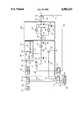
- the FIGUREshows a circuit diagram of a phase locked loop in accordance with the present invention.
- a PLL 100 in accordance with the inventionoperates to provide a frequency-variable output signal 150 from a voltage-controlled oscillator 148 that is controlled by a control signal 146.
- a divided signal 158is compared, in a phase comparator 106, with a reference signal 105 provided by a frequency source, or oscillator 102 (that produces a source-frequency signal 103) in conjunction with a divide-by-R divider 104 (that divides the source-frequency signal 103 to the desired frequency).
- the divided signal 158is produced by a divide-by-N divider that is disposed between the output of the VCO 148 and the phase comparator 106.
- the value of the divisor "N"is determined by a microprocessor 162.
- various reference signals 105may be provided.
- the information representing the choice of the divisor Nis first applied by the microprocessor 162 to a shift register 156, through a microprocessor line 164, and then it is applied to the divider 152, through a bus line 154.
- the microprocessor 162also provides information representing choice of the divisor "R" to the divider 104 through a microprocessor line 164, and then it is applied to the divider 104, through a bus line 160.
- the divider 152divides the output signal 150 by N and applies the divided signal 158 to the phase detector 106.
- the phase detector 106compares the phase of the divided signal 158 with the reference signal 105.
- the phase detector 106provides a phase comparison signal 121, representing the detected phase difference, to a low-pass loop filter 130.
- the phase comparison signal 121is filtered by a low-pass loop filter 130 to filter noise and spurious energy to prevent unwanted modulation of the VCO 148.
- the low-pass loop filter 130provides a filtered control signal 146 to the VCO to set the frequency of the output signal 150.
- the phase detector 106includes a conventional logic control circuit 108, such as the one discused in U.S. Pat. No. 4,714,899, to Kurtzman et al. (hereby incorporated by reference).
- the logic control circuit 108detects the leading edge of a pulse of the reference signal 105, the logic control circuit 108 provides a signal 109 that turns on the switch 110, thus enabling a biased transistor 114.
- the charging of the capacitor 116is initiated by closing the switch 110.
- a resistor 112is disposed between the switch 110 and the transistor 114 to form a source of contact current (I) for charging the ramp capacitor 116.
- the ramp capacitorAs the ramp capacitor charges, it provides a well-known voltage versus time "ramp" characteristic having a slew rate (i.e., slope) equal to the difference between the sampled voltages divided by the different in the sampled times.
- the logic control circuit 108detects the leading edge of a pulse of the divided signal 158, the logic control circuit 108 provides a signal (not shown) that turns on the switch 110, thus enabling a biased transistor 114.
- a sawtooth wave(the voltage across the capacitors 116 and 122 versus time) is formed, having the period of the reference signal 105.
- the microprocessor 162provides a switching signal 123 to a transistor 128 (through the shift register 156 and a resistor 124) that drives the transitor 128 into saturation, thus coupling a second ramp capacitor 122 to ground in parallel with the first ramp capacitor 116.
- the resulting increase in capacitanceincreases the slew rate of the phase detector and consequently, decreases the lock time of the PLL 100.
- the slew ratecan be selectively adjusted to optimize the phase detector gain with respect to different reference signals 105 (e.g., first and second reference signals).
- the logic control circuit 108samples the sawtooth voltage by closing a sampling switch 118 for a window of time and letting a hold capacitor 126 charge to the sampled voltage. The charge established on the hold capacitor 126 remains approximately constant until the next sampling. Thus, an error voltage 121 is provided by the phase detector 106 to the loop filter 130.
- the low-pass filter 130is a conventional adaptive loop filter.
- the amplifier 132amplifies the error voltage 121.
- One terminal of a resistor 136is coupled to the output of the amplifier 132 at a node 135 and the other terminal is coupled to the VCO 148 at a node 137.
- a terminal of a resistor 138 and a terminal of a capacitor 142are coupled to the node 137.
- the opposite terminals of the resistor 138 and the capacitor 142are coupled together at a common node 141.
- a capacitor 144is disposed between the node 141 and ground to complete a low-pass filter.
- a switch 134is disposed between the nodes 135 and 137, so that a signal (not shown), produced by the microprocessor 162, closes the switch 134, bypassing the filter.
- An alternative current source 170may be used for adjusting the slew rate (and gain) of the phase detector 106 in lieu of using the transistor 128 and capacitor 122. It will be appreciated by those skilled in the art that, the slew rate of a sample and hold phase detector may be increased by increasing the current for charging the ramp capacitor.
- the circuit 170uses a PNP transistor 174 as a switch to provide the current I through a resistor 172 in response to the switching signal 123 provided by the shift register 156. A pair of resistor 176 and 178 are provided at the base of the transistor 174 for biasing purposes.
Landscapes
- Stabilization Of Oscillater, Synchronisation, Frequency Synthesizers (AREA)
Abstract
Description
This invention relates generally to phase locked loops (PLLs), and more specifically to those PLLs using sample and hold phase detectors.
Conventional PLLs typically include a reference oscillator and a reference divider, a phase detector, a feedback divider, a low-pass loop filter, and a voltage-controlled oscillator (VCO). The fundamentals of PLL operation are well understood by contemporary designers.
The low-pass filters used in such conventional PLLs typically have a narrow passband, causing the time constant of the PLL to be large. A large time constant is undesirable for many radio applications of PLLs where a fast lock rate (i.e., the time it takes the PLL to lock onto a frequency) is required. One possible solution to this problem is to use a loop filter with a broader bandwidth. However, that solution has the detriment that it makes the input to the VCO noisier. Thus, lock time would be improved at the expense of performance.
Moreover, in some radio PLL circuits, more than one reference frequency is used, to generate the first local oscillator and the transmit frequencies, and a high-frequency first intermediate frequency is also used. This causes a large difference in operating frequencies. Therefore, the loop bandwidth must be a compromise for both bands of operation. That compromise degrades the lock time performance.
Other radio applications for PLLs, such as frequency scanning systems, require a faster lock time for receive-to-receive transitions than for receive-to-transmit transitions. In such cases, the loop gain must be compromised with respect to the lock times required causing degradation in each lock time.
Accordingly, it is an object of the present invention to provide a phase locked loop that avoids the detriments of the prior art.
Briefly, according to the invention, a phase locked loop comprises means for providing an output signal, means for providing a reference signal, means for dividing the output signal by a predetermined divisor, phase detector means, and means for adjusting the gain of the phase detector means. The means for dividing the output signal provides a divided signal to the phase detector means for comparing the phase of the divided signal with the phase of the reference signal. The means for comparing the phase of the divided signal with the phase of the reference signal has an adjustable gain and is coupled to the means for providing a output signal.
The FIGURE shows a circuit diagram of a phase locked loop in accordance with the present invention.
Referring to the FIGURE, aPLL 100 in accordance with the invention is shown. The PLL 100 operates to provide a frequency-variable output signal 150 from a voltage-controlledoscillator 148 that is controlled by acontrol signal 146. To generate thecontrol signal 146, a dividedsignal 158 is compared, in aphase comparator 106, with areference signal 105 provided by a frequency source, or oscillator 102 (that produces a source-frequency signal 103) in conjunction with a divide-by-R divider 104 (that divides the source-frequency signal 103 to the desired frequency). The dividedsignal 158 is produced by a divide-by-N divider that is disposed between the output of theVCO 148 and thephase comparator 106. The value of the divisor "N" is determined by amicroprocessor 162. Thus, various reference signals 105 (differing in frequency) may be provided. The information representing the choice of the divisor N is first applied by themicroprocessor 162 to ashift register 156, through amicroprocessor line 164, and then it is applied to thedivider 152, through abus line 154. Themicroprocessor 162 also provides information representing choice of the divisor "R" to thedivider 104 through amicroprocessor line 164, and then it is applied to thedivider 104, through abus line 160.
Thedivider 152 divides theoutput signal 150 by N and applies thedivided signal 158 to thephase detector 106. Thephase detector 106 compares the phase of the dividedsignal 158 with thereference signal 105. Thephase detector 106 provides aphase comparison signal 121, representing the detected phase difference, to a low-pass loop filter 130. Thephase comparison signal 121 is filtered by a low-pass loop filter 130 to filter noise and spurious energy to prevent unwanted modulation of theVCO 148. The low-pass loop filter 130 provides a filteredcontrol signal 146 to the VCO to set the frequency of theoutput signal 150.
Thephase detector 106 includes a conventionallogic control circuit 108, such as the one discused in U.S. Pat. No. 4,714,899, to Kurtzman et al. (hereby incorporated by reference). When thelogic control circuit 108 detects the leading edge of a pulse of thereference signal 105, thelogic control circuit 108 provides asignal 109 that turns on theswitch 110, thus enabling abiased transistor 114. Thus, the charging of thecapacitor 116 is initiated by closing theswitch 110. Aresistor 112 is disposed between theswitch 110 and thetransistor 114 to form a source of contact current (I) for charging theramp capacitor 116. As the ramp capacitor charges, it provides a well-known voltage versus time "ramp" characteristic having a slew rate (i.e., slope) equal to the difference between the sampled voltages divided by the different in the sampled times. When thelogic control circuit 108 detects the leading edge of a pulse of the dividedsignal 158, thelogic control circuit 108 provides a signal (not shown) that turns on theswitch 110, thus enabling abiased transistor 114. Thus a sawtooth wave (the voltage across thecapacitors reference signal 105.
Increasing the slew rate of thephase detector 106 decreases the lock time of that circuit. A greater slew rate also compromises noise performance. However, the noise performance is less critical during receive-to-receive or receive-to-talk transition times. Therefore, during such times, themicroprocessor 162 provides aswitching signal 123 to a transistor 128 (through theshift register 156 and a resistor 124) that drives thetransitor 128 into saturation, thus coupling asecond ramp capacitor 122 to ground in parallel with thefirst ramp capacitor 116. The resulting increase in capacitance increases the slew rate of the phase detector and consequently, decreases the lock time of thePLL 100. The slew rate can be selectively adjusted to optimize the phase detector gain with respect to different reference signals 105 (e.g., first and second reference signals).
Thelogic control circuit 108 samples the sawtooth voltage by closing asampling switch 118 for a window of time and letting ahold capacitor 126 charge to the sampled voltage. The charge established on thehold capacitor 126 remains approximately constant until the next sampling. Thus, anerror voltage 121 is provided by thephase detector 106 to theloop filter 130.
The low-pass filter 130 is a conventional adaptive loop filter. Theamplifier 132 amplifies theerror voltage 121. One terminal of aresistor 136 is coupled to the output of theamplifier 132 at anode 135 and the other terminal is coupled to theVCO 148 at anode 137. A terminal of aresistor 138 and a terminal of acapacitor 142 are coupled to thenode 137. The opposite terminals of theresistor 138 and thecapacitor 142 are coupled together at acommon node 141. Acapacitor 144 is disposed between thenode 141 and ground to complete a low-pass filter. Aswitch 134 is disposed between thenodes microprocessor 162, closes theswitch 134, bypassing the filter.
An alternativecurrent source 170 may be used for adjusting the slew rate (and gain) of thephase detector 106 in lieu of using thetransistor 128 andcapacitor 122. It will be appreciated by those skilled in the art that, the slew rate of a sample and hold phase detector may be increased by increasing the current for charging the ramp capacitor. Thecircuit 170 uses aPNP transistor 174 as a switch to provide the current I through aresistor 172 in response to theswitching signal 123 provided by theshift register 156. A pair ofresistor transistor 174 for biasing purposes.
Claims (6)
1. A phase locked loop comprising:
controlled oscillator means for providing an output signal, having a variable frequency responsive to a control signal;
reference means for providing first and second reference signals;
divider means for dividing the output signal by a predetermined divisor, to provide a divided signal;
sample and hold phase detector means, having adjustable gain and slew rate, for comparing the phase of alternatively, the first and second reference signals with the phase of the divided signal; and:
means for selectively adjusting the slew rate of the sample and hold phase detector means to optimize the adjustable gain of the phase detector means with respect to, alternatively, the first and second reference signals.
2. The phase locked loop of claim 1, wherein the phase detector means has an adjustable slew rate, and the means for adjusting the gain of the phase detector means comprises a current source for applying a current signal to an adjustable capacitance means for determining the slew rate.
3. The phase locked loop of claim 1, wherein the phase detector means has an adjustable slew rate, and the means for adjusting the gain of the phase detector means comprises a variable current source coupled to the adjustable capacitance means for providing a variable current signal to the adjustable capacitance means, and for determining the the slew rate,
4. The phase locked loop of claim 1, further comprising an adaptive low-pass filter, disposed between the phase detector means and the controlled oscillator means.
5. The phase locked loop of claim 1, wherein the controlled oscillator means comprises a voltage-controlled oscillator.
6. The phase locked loop of claim 5, wherein the divider comprises a divider.
Priority Applications (1)
| Application Number | Priority Date | Filing Date | Title |
|---|---|---|---|
| US07/402,715US4980653A (en) | 1989-09-05 | 1989-09-05 | Phase locked loop |
Applications Claiming Priority (1)
| Application Number | Priority Date | Filing Date | Title |
|---|---|---|---|
| US07/402,715US4980653A (en) | 1989-09-05 | 1989-09-05 | Phase locked loop |
Publications (1)
| Publication Number | Publication Date |
|---|---|
| US4980653Atrue US4980653A (en) | 1990-12-25 |
Family
ID=23593032
Family Applications (1)
| Application Number | Title | Priority Date | Filing Date |
|---|---|---|---|
| US07/402,715Expired - LifetimeUS4980653A (en) | 1989-09-05 | 1989-09-05 | Phase locked loop |
Country Status (1)
| Country | Link |
|---|---|
| US (1) | US4980653A (en) |
Cited By (44)
| Publication number | Priority date | Publication date | Assignee | Title |
|---|---|---|---|---|
| US5146187A (en)* | 1991-07-01 | 1992-09-08 | Ericsson Ge Mobile Communications Inc. | Synthesizer loop filter for scanning receivers |
| US5157341A (en)* | 1989-08-22 | 1992-10-20 | Plessey Overseas Limited | Phase detector |
| US5200712A (en)* | 1991-12-26 | 1993-04-06 | Zenith Electronics Corporation | Variable speed phase locked loop |
| US5220294A (en)* | 1990-05-21 | 1993-06-15 | Nec Corporation | Phase-locked loop circuit |
| EP0570819A1 (en)* | 1992-05-20 | 1993-11-24 | Siemens Aktiengesellschaft | Method for controlling the parameters of A PLL |
| US5307071A (en)* | 1992-04-17 | 1994-04-26 | Hughes Aircraft Company | Low noise frequency synthesizer using half integer dividers and analog gain compensation |
| US5339050A (en)* | 1993-04-27 | 1994-08-16 | National Semiconductor Corp. | Frequency synthesizing phase lock loop with unvarying loop parameters |
| EP0587760A4 (en)* | 1991-06-05 | 1994-08-24 | Motorola Inc | Radio with fast lock phase-locked loop |
| US5404250A (en)* | 1989-10-30 | 1995-04-04 | Hitachi, Ltd. | Magnetic disk storage apparatus with phase sync circuit having controllable response characteristic |
| US5420545A (en)* | 1993-03-10 | 1995-05-30 | National Semiconductor Corporation | Phase lock loop with selectable frequency switching time |
| US5498998A (en)* | 1992-11-16 | 1996-03-12 | Gehrke; James K. | Method for adjusting the output frequency of a frequency synthesizer |
| US5542113A (en)* | 1994-09-06 | 1996-07-30 | Motorola, Inc. | Carrier derived frequency stabilizer for a radio communication transmitter |
| US5559474A (en)* | 1994-05-26 | 1996-09-24 | Matsushita Electric Industrial Co., Ltd. | Frequency synthesizer with controllable loop filter |
| EP0794609A1 (en)* | 1996-03-08 | 1997-09-10 | STMicroelectronics S.r.l. | An integrated circuit with automatic compensation for deviations of the capacitances from nominal values |
| US5684434A (en)* | 1995-10-30 | 1997-11-04 | Cypress Semiconductor | Erasable and programmable single chip clock generator |
| US5805871A (en)* | 1995-07-21 | 1998-09-08 | Ricoh Company Ltd. | System and method for phase-synchronous, flexible-frequency clocking and messaging |
| US6137372A (en)* | 1998-05-29 | 2000-10-24 | Silicon Laboratories Inc. | Method and apparatus for providing coarse and fine tuning control for synthesizing high-frequency signals for wireless communications |
| US6147567A (en)* | 1998-05-29 | 2000-11-14 | Silicon Laboratories Inc. | Method and apparatus for providing analog and digitally controlled capacitances for synthesizing high-frequency signals for wireless communications |
| US6150891A (en)* | 1998-05-29 | 2000-11-21 | Silicon Laboratories, Inc. | PLL synthesizer having phase shifted control signals |
| US6167245A (en)* | 1998-05-29 | 2000-12-26 | Silicon Laboratories, Inc. | Method and apparatus for operating a PLL with a phase detector/sample hold circuit for synthesizing high-frequency signals for wireless communications |
| US6226506B1 (en) | 1998-05-29 | 2001-05-01 | Silicon Laboratories, Inc. | Method and apparatus for eliminating floating voltage nodes within a discreetly variable capacitance used for synthesizing high-frequency signals for wireless communications |
| US6304146B1 (en) | 1998-05-29 | 2001-10-16 | Silicon Laboratories, Inc. | Method and apparatus for synthesizing dual band high-frequency signals for wireless communications |
| US6308055B1 (en) | 1998-05-29 | 2001-10-23 | Silicon Laboratories, Inc. | Method and apparatus for operating a PLL for synthesizing high-frequency signals for wireless communications |
| US6311050B1 (en) | 1998-05-29 | 2001-10-30 | Silicon Laboratories, Inc. | Single integrated circuit phase locked loop for synthesizing high-frequency signals for wireless communications and method for operating same |
| US6323735B1 (en) | 2000-05-25 | 2001-11-27 | Silicon Laboratories, Inc. | Method and apparatus for synthesizing high-frequency signals utilizing on-package oscillator circuit inductors |
| US6549764B2 (en) | 1998-05-29 | 2003-04-15 | Silicon Laboratories Inc. | Method and apparatus for selecting capacitance amounts to vary the output frequency of a controlled oscillator |
| US6574288B1 (en) | 1998-05-29 | 2003-06-03 | Silicon Laboratories Inc. | Method and apparatus for adjusting a digital control word to tune synthesized high-frequency signals for wireless communications |
| US6664860B2 (en) | 1997-02-05 | 2003-12-16 | Fox Enterprises, Inc. | Programmable oscillator circuit and method |
| US6760575B2 (en) | 1998-05-29 | 2004-07-06 | Silicon Laboratories, Inc. | Method and apparatus for generating a variable capacitance for synthesizing high-frequency signals for wireless communications |
| US6965272B2 (en) | 1997-02-05 | 2005-11-15 | Fox Enterprises, Inc. | Worldwide marketing logistics network including strategically located centers for frequency programming crystal oscillators to customer specification |
| US6993314B2 (en) | 1998-05-29 | 2006-01-31 | Silicon Laboratories Inc. | Apparatus for generating multiple radio frequencies in communication circuitry and associated methods |
| US7035607B2 (en) | 1998-05-29 | 2006-04-25 | Silicon Laboratories Inc. | Systems and methods for providing an adjustable reference signal to RF circuitry |
| US7092675B2 (en) | 1998-05-29 | 2006-08-15 | Silicon Laboratories | Apparatus and methods for generating radio frequencies in communication circuitry using multiple control signals |
| US7221921B2 (en) | 1998-05-29 | 2007-05-22 | Silicon Laboratories | Partitioning of radio-frequency apparatus |
| US7242912B2 (en) | 1998-05-29 | 2007-07-10 | Silicon Laboratories Inc. | Partitioning of radio-frequency apparatus |
| US20080203977A1 (en)* | 2006-11-10 | 2008-08-28 | Nandakishore Raimar | Boost buffer aid for reference buffer |
| US20080258797A1 (en)* | 2007-04-18 | 2008-10-23 | Cypress Semiconductor Corp. | Non-resistive load driver |
| US20080267264A1 (en)* | 2007-04-26 | 2008-10-30 | Scranton Timothy F | Low phase noise clock generator for device under test |
| FR2934443A1 (en)* | 2008-07-27 | 2010-01-29 | Renault Sas | ANTI-COUPLE FILTRATION METHOD AND DEVICE FOR MOTOR VEHICLE |
| US7893772B1 (en) | 2007-12-03 | 2011-02-22 | Cypress Semiconductor Corporation | System and method of loading a programmable counter |
| US8035455B1 (en) | 2005-12-21 | 2011-10-11 | Cypress Semiconductor Corporation | Oscillator amplitude control network |
| US8073042B1 (en) | 2005-04-13 | 2011-12-06 | Cypress Semiconductor Corporation | Recursive range controller |
| US8364870B2 (en) | 2010-09-30 | 2013-01-29 | Cypress Semiconductor Corporation | USB port connected to multiple USB compliant devices |
| US9667240B2 (en) | 2011-12-02 | 2017-05-30 | Cypress Semiconductor Corporation | Systems and methods for starting up analog circuits |
Citations (4)
| Publication number | Priority date | Publication date | Assignee | Title |
|---|---|---|---|---|
| US4330758A (en)* | 1980-02-20 | 1982-05-18 | Motorola, Inc. | Synchronized frequency synthesizer with high speed lock |
| US4568888A (en)* | 1983-11-08 | 1986-02-04 | Trw Inc. | PLL Fast frequency synthesizer with memories for coarse tuning and loop gain correction |
| US4714899A (en)* | 1986-09-30 | 1987-12-22 | Motorola, Inc. | Frequency synthesizer |
| US4745372A (en)* | 1985-10-17 | 1988-05-17 | Matsushita Electric Industrial Co., Ltd. | Phase-locked-loop circuit having a charge pump |
- 1989
- 1989-09-05USUS07/402,715patent/US4980653A/ennot_activeExpired - Lifetime
Patent Citations (4)
| Publication number | Priority date | Publication date | Assignee | Title |
|---|---|---|---|---|
| US4330758A (en)* | 1980-02-20 | 1982-05-18 | Motorola, Inc. | Synchronized frequency synthesizer with high speed lock |
| US4568888A (en)* | 1983-11-08 | 1986-02-04 | Trw Inc. | PLL Fast frequency synthesizer with memories for coarse tuning and loop gain correction |
| US4745372A (en)* | 1985-10-17 | 1988-05-17 | Matsushita Electric Industrial Co., Ltd. | Phase-locked-loop circuit having a charge pump |
| US4714899A (en)* | 1986-09-30 | 1987-12-22 | Motorola, Inc. | Frequency synthesizer |
Non-Patent Citations (2)
| Title |
|---|
| Motorola, "Operation of the MC145159 PLL Frequency Synthesizer with Analog Phase Detector", (1987). |
| Motorola, Operation of the MC145159 PLL Frequency Synthesizer with Analog Phase Detector , (1987).* |
Cited By (75)
| Publication number | Priority date | Publication date | Assignee | Title |
|---|---|---|---|---|
| US5157341A (en)* | 1989-08-22 | 1992-10-20 | Plessey Overseas Limited | Phase detector |
| US5404250A (en)* | 1989-10-30 | 1995-04-04 | Hitachi, Ltd. | Magnetic disk storage apparatus with phase sync circuit having controllable response characteristic |
| US5633766A (en)* | 1989-10-30 | 1997-05-27 | Hitachi, Ltd. | Magnetic disk storage apparatus with phase sync circuit having controllable response characteristics |
| US6266200B1 (en) | 1989-10-30 | 2001-07-24 | Hitachi, Ltd | Magnetic disk storage apparatus |
| US5999353A (en)* | 1989-10-30 | 1999-12-07 | Hitachi, Ltd. | Magnetic disk storage apparatus with phase sync circuit having controllable response characteristic |
| US5220294A (en)* | 1990-05-21 | 1993-06-15 | Nec Corporation | Phase-locked loop circuit |
| EP0587760A4 (en)* | 1991-06-05 | 1994-08-24 | Motorola Inc | Radio with fast lock phase-locked loop |
| US5146187A (en)* | 1991-07-01 | 1992-09-08 | Ericsson Ge Mobile Communications Inc. | Synthesizer loop filter for scanning receivers |
| US5200712A (en)* | 1991-12-26 | 1993-04-06 | Zenith Electronics Corporation | Variable speed phase locked loop |
| AU656849B2 (en)* | 1992-04-17 | 1995-02-16 | Hughes Aircraft Company | Low noise frequency synthesizer using half integer dividers and anlog gain compensation |
| US5307071A (en)* | 1992-04-17 | 1994-04-26 | Hughes Aircraft Company | Low noise frequency synthesizer using half integer dividers and analog gain compensation |
| EP0570819A1 (en)* | 1992-05-20 | 1993-11-24 | Siemens Aktiengesellschaft | Method for controlling the parameters of A PLL |
| US5498998A (en)* | 1992-11-16 | 1996-03-12 | Gehrke; James K. | Method for adjusting the output frequency of a frequency synthesizer |
| US5420545A (en)* | 1993-03-10 | 1995-05-30 | National Semiconductor Corporation | Phase lock loop with selectable frequency switching time |
| US5339050A (en)* | 1993-04-27 | 1994-08-16 | National Semiconductor Corp. | Frequency synthesizing phase lock loop with unvarying loop parameters |
| US5559474A (en)* | 1994-05-26 | 1996-09-24 | Matsushita Electric Industrial Co., Ltd. | Frequency synthesizer with controllable loop filter |
| US5542113A (en)* | 1994-09-06 | 1996-07-30 | Motorola, Inc. | Carrier derived frequency stabilizer for a radio communication transmitter |
| US5805871A (en)* | 1995-07-21 | 1998-09-08 | Ricoh Company Ltd. | System and method for phase-synchronous, flexible-frequency clocking and messaging |
| US5877656A (en)* | 1995-10-30 | 1999-03-02 | Cypress Semiconductor Corp. | Programmable clock generator |
| US5684434A (en)* | 1995-10-30 | 1997-11-04 | Cypress Semiconductor | Erasable and programmable single chip clock generator |
| US6433645B1 (en) | 1995-10-30 | 2002-08-13 | Cypress Semiconductor Corp. | Programmable clock generator |
| US5821829A (en)* | 1996-03-08 | 1998-10-13 | Sgs-Thomson Miroelectronics S.R.L. | Integrated circuit waith automatic compensation for deviations of the capacitances from nominal values |
| EP0794609A1 (en)* | 1996-03-08 | 1997-09-10 | STMicroelectronics S.r.l. | An integrated circuit with automatic compensation for deviations of the capacitances from nominal values |
| US6965272B2 (en) | 1997-02-05 | 2005-11-15 | Fox Enterprises, Inc. | Worldwide marketing logistics network including strategically located centers for frequency programming crystal oscillators to customer specification |
| US6954113B2 (en) | 1997-02-05 | 2005-10-11 | Fox Electronics, Inc. | Programmable oscillator circuit |
| US6664860B2 (en) | 1997-02-05 | 2003-12-16 | Fox Enterprises, Inc. | Programmable oscillator circuit and method |
| US6549764B2 (en) | 1998-05-29 | 2003-04-15 | Silicon Laboratories Inc. | Method and apparatus for selecting capacitance amounts to vary the output frequency of a controlled oscillator |
| US7221921B2 (en) | 1998-05-29 | 2007-05-22 | Silicon Laboratories | Partitioning of radio-frequency apparatus |
| US6308055B1 (en) | 1998-05-29 | 2001-10-23 | Silicon Laboratories, Inc. | Method and apparatus for operating a PLL for synthesizing high-frequency signals for wireless communications |
| US6311050B1 (en) | 1998-05-29 | 2001-10-30 | Silicon Laboratories, Inc. | Single integrated circuit phase locked loop for synthesizing high-frequency signals for wireless communications and method for operating same |
| US6317006B1 (en) | 1998-05-29 | 2001-11-13 | Silicon Laboratories, Inc. | Frequency synthesizer utilizing phase shifted control signals |
| US7353011B2 (en) | 1998-05-29 | 2008-04-01 | Silicon Laboratories Inc. | Method and apparatus for operating a PLL for synthesizing high-frequency signals for wireless communications |
| US6388536B1 (en) | 1998-05-29 | 2002-05-14 | Silicon Laboratories Inc. | Method and apparatus for providing coarse and fine tuning control for synthesizing high-frequency signals for wireless communications |
| US6226506B1 (en) | 1998-05-29 | 2001-05-01 | Silicon Laboratories, Inc. | Method and apparatus for eliminating floating voltage nodes within a discreetly variable capacitance used for synthesizing high-frequency signals for wireless communications |
| US6483390B2 (en) | 1998-05-29 | 2002-11-19 | Silicon Laboratories Inc. | Method and apparatus for synthesizing dual band high-frequency signals for wireless communications |
| US6549765B2 (en) | 1998-05-29 | 2003-04-15 | Silicon Laboratories, Inc. | Phase locked loop circuitry for synthesizing high-frequency signals and associated method |
| US6167245A (en)* | 1998-05-29 | 2000-12-26 | Silicon Laboratories, Inc. | Method and apparatus for operating a PLL with a phase detector/sample hold circuit for synthesizing high-frequency signals for wireless communications |
| US6574288B1 (en) | 1998-05-29 | 2003-06-03 | Silicon Laboratories Inc. | Method and apparatus for adjusting a digital control word to tune synthesized high-frequency signals for wireless communications |
| US20030119467A1 (en)* | 1998-05-29 | 2003-06-26 | Silicon Laboratories, Inc. | Method and apparatus for operating a PLL for synthesizing high-frequency signals for wireless communications |
| US6150891A (en)* | 1998-05-29 | 2000-11-21 | Silicon Laboratories, Inc. | PLL synthesizer having phase shifted control signals |
| US20040075506A1 (en)* | 1998-05-29 | 2004-04-22 | Silicon Laboratories Inc. | Method and apparatus for operating a PLL with a phase detector/sample hold circuit for synthesizing high-frequency signals for wireless communications |
| US6760575B2 (en) | 1998-05-29 | 2004-07-06 | Silicon Laboratories, Inc. | Method and apparatus for generating a variable capacitance for synthesizing high-frequency signals for wireless communications |
| US6147567A (en)* | 1998-05-29 | 2000-11-14 | Silicon Laboratories Inc. | Method and apparatus for providing analog and digitally controlled capacitances for synthesizing high-frequency signals for wireless communications |
| US6137372A (en)* | 1998-05-29 | 2000-10-24 | Silicon Laboratories Inc. | Method and apparatus for providing coarse and fine tuning control for synthesizing high-frequency signals for wireless communications |
| US6965761B2 (en) | 1998-05-29 | 2005-11-15 | Silicon Laboratories, Inc. | Controlled oscillator circuitry for synthesizing high-frequency signals and associated method |
| US20050266817A1 (en)* | 1998-05-29 | 2005-12-01 | Silicon Laboratories, Inc. | Method and apparatus for operating a PLL for synthesizing high-frequency signals for wireless communications |
| US6993307B2 (en) | 1998-05-29 | 2006-01-31 | Silicon Laboratories, Inc. | Method and apparatus for operating a PLL with a phase detector/sample hold circuit for synthesizing high-frequency signals for wireless communications |
| US6993314B2 (en) | 1998-05-29 | 2006-01-31 | Silicon Laboratories Inc. | Apparatus for generating multiple radio frequencies in communication circuitry and associated methods |
| US7035607B2 (en) | 1998-05-29 | 2006-04-25 | Silicon Laboratories Inc. | Systems and methods for providing an adjustable reference signal to RF circuitry |
| US7092675B2 (en) | 1998-05-29 | 2006-08-15 | Silicon Laboratories | Apparatus and methods for generating radio frequencies in communication circuitry using multiple control signals |
| US7200364B2 (en) | 1998-05-29 | 2007-04-03 | Silicon Laboratories | Frequency modification circuitry for use in radio-frequency communication apparatus and associated methods |
| US6304146B1 (en) | 1998-05-29 | 2001-10-16 | Silicon Laboratories, Inc. | Method and apparatus for synthesizing dual band high-frequency signals for wireless communications |
| US7242912B2 (en) | 1998-05-29 | 2007-07-10 | Silicon Laboratories Inc. | Partitioning of radio-frequency apparatus |
| US6323735B1 (en) | 2000-05-25 | 2001-11-27 | Silicon Laboratories, Inc. | Method and apparatus for synthesizing high-frequency signals utilizing on-package oscillator circuit inductors |
| US8526558B1 (en) | 2005-04-13 | 2013-09-03 | Cypress Semiconductor Corporation | Recursive range controller |
| US8073042B1 (en) | 2005-04-13 | 2011-12-06 | Cypress Semiconductor Corporation | Recursive range controller |
| US8035455B1 (en) | 2005-12-21 | 2011-10-11 | Cypress Semiconductor Corporation | Oscillator amplitude control network |
| US20080203977A1 (en)* | 2006-11-10 | 2008-08-28 | Nandakishore Raimar | Boost buffer aid for reference buffer |
| US8564252B2 (en) | 2006-11-10 | 2013-10-22 | Cypress Semiconductor Corporation | Boost buffer aid for reference buffer |
| US11876510B2 (en) | 2007-04-18 | 2024-01-16 | Monterey Research, Llc | Load driver |
| US8035401B2 (en) | 2007-04-18 | 2011-10-11 | Cypress Semiconductor Corporation | Self-calibrating driver for charging a capacitive load to a desired voltage |
| US9923559B2 (en) | 2007-04-18 | 2018-03-20 | Monterey Research, Llc | Load driver |
| US8164365B2 (en) | 2007-04-18 | 2012-04-24 | Cypress Semiconductor Corporation | Non-resistive load driver |
| US11223352B2 (en) | 2007-04-18 | 2022-01-11 | Monterey Research, Llc | Load driver |
| US20080258797A1 (en)* | 2007-04-18 | 2008-10-23 | Cypress Semiconductor Corp. | Non-resistive load driver |
| US8570073B2 (en) | 2007-04-18 | 2013-10-29 | Cypress Semiconductor Corporation | Load driver |
| US10418990B2 (en) | 2007-04-18 | 2019-09-17 | Monterey Research, Llc | Load driver |
| US9124264B2 (en) | 2007-04-18 | 2015-09-01 | Cypress Semiconductor Corporation | Load driver |
| US20080267264A1 (en)* | 2007-04-26 | 2008-10-30 | Scranton Timothy F | Low phase noise clock generator for device under test |
| US7893772B1 (en) | 2007-12-03 | 2011-02-22 | Cypress Semiconductor Corporation | System and method of loading a programmable counter |
| EP2149987A1 (en)* | 2008-07-27 | 2010-02-03 | Renault s.a.s. | Filtering method and system for avoiding jolts in vehicles |
| FR2934443A1 (en)* | 2008-07-27 | 2010-01-29 | Renault Sas | ANTI-COUPLE FILTRATION METHOD AND DEVICE FOR MOTOR VEHICLE |
| US8645598B2 (en) | 2010-09-30 | 2014-02-04 | Cypress Semiconductor Corp. | Downstream interface ports for connecting to USB capable devices |
| US8364870B2 (en) | 2010-09-30 | 2013-01-29 | Cypress Semiconductor Corporation | USB port connected to multiple USB compliant devices |
| US9667240B2 (en) | 2011-12-02 | 2017-05-30 | Cypress Semiconductor Corporation | Systems and methods for starting up analog circuits |
Similar Documents
| Publication | Publication Date | Title |
|---|---|---|
| US4980653A (en) | Phase locked loop | |
| EP0684701B1 (en) | Frequency synthesizer | |
| US6140882A (en) | Phase lock loop enabling smooth loop bandwidth switching | |
| US4970472A (en) | Compensated phase locked loop circuit | |
| US5146187A (en) | Synthesizer loop filter for scanning receivers | |
| US4937536A (en) | Fast settling phase lock loop | |
| US4205272A (en) | Phase-locked loop circuit for use in synthesizer tuner and synthesizer tuner incorporating same | |
| US6549599B2 (en) | Stable phase locked loop having separated pole | |
| US6900675B2 (en) | All digital PLL trimming circuit | |
| US4935706A (en) | Tuning apparatus for high speed phase locked loops | |
| US6759838B2 (en) | Phase-locked loop with dual-mode phase/frequency detection | |
| US5315623A (en) | Dual mode phase-locked loop | |
| US4546329A (en) | Frequency synthesizers adaptive loop filter with compensation for transients | |
| MXPA95003264A (en) | Control system, rap activation | |
| US11411566B2 (en) | Charge pump | |
| US5675292A (en) | Phase lock loop enabling smooth loop bandwidth switching over a wide range | |
| US6380810B1 (en) | Reduced lock time for a phase locked loop | |
| EP0435881B1 (en) | Sample-and-hold phase detector for use in a phase locked loop | |
| US7023249B1 (en) | Phase locked loop with low phase noise and fast tune time | |
| EP0418862B1 (en) | Frequency modulation circuit using VCO | |
| EP0599505A1 (en) | Tunable resonance circuit for a voltage controlled oscillator | |
| US4345219A (en) | Frequency agile hold-sample-hold phase detector | |
| JPH02111123A (en) | Synchronizing circuit of variable frequency oscillator | |
| JPH06276090A (en) | PLL circuit | |
| EP0844739A1 (en) | Phase-locked loop circuit, particularly for a transmitter-receiver system |
Legal Events
| Date | Code | Title | Description |
|---|---|---|---|
| AS | Assignment | Owner name:MOTOROLA, INC., SCHAUMBURG, IL A CORP. OF DELAWARE Free format text:ASSIGNMENT OF ASSIGNORS INTEREST.;ASSIGNOR:SHEPHERD, WAYNE P.;REEL/FRAME:005141/0158 Effective date:19890829 | |
| STCF | Information on status: patent grant | Free format text:PATENTED CASE | |
| FEPP | Fee payment procedure | Free format text:PAYOR NUMBER ASSIGNED (ORIGINAL EVENT CODE: ASPN); ENTITY STATUS OF PATENT OWNER: LARGE ENTITY | |
| FPAY | Fee payment | Year of fee payment:4 | |
| FPAY | Fee payment | Year of fee payment:8 | |
| FPAY | Fee payment | Year of fee payment:12 |