US4978638A - Method for attaching heat sink to plastic packaged electronic component - Google Patents
Method for attaching heat sink to plastic packaged electronic componentDownload PDFInfo
- Publication number
- US4978638A US4978638AUS07/454,655US45465589AUS4978638AUS 4978638 AUS4978638 AUS 4978638AUS 45465589 AUS45465589 AUS 45465589AUS 4978638 AUS4978638 AUS 4978638A
- Authority
- US
- United States
- Prior art keywords
- heat sink
- plastic
- component
- plastic packaged
- pair
- Prior art date
- Legal status (The legal status is an assumption and is not a legal conclusion. Google has not performed a legal analysis and makes no representation as to the accuracy of the status listed.)
- Expired - Fee Related
Links
Images

Classifications
- H—ELECTRICITY
- H01—ELECTRIC ELEMENTS
- H01L—SEMICONDUCTOR DEVICES NOT COVERED BY CLASS H10
- H01L23/00—Details of semiconductor or other solid state devices
- H01L23/34—Arrangements for cooling, heating, ventilating or temperature compensation ; Temperature sensing arrangements
- H01L23/40—Mountings or securing means for detachable cooling or heating arrangements ; fixed by friction, plugs or springs
- H01L23/4093—Snap-on arrangements, e.g. clips
- H—ELECTRICITY
- H01—ELECTRIC ELEMENTS
- H01L—SEMICONDUCTOR DEVICES NOT COVERED BY CLASS H10
- H01L2924/00—Indexing scheme for arrangements or methods for connecting or disconnecting semiconductor or solid-state bodies as covered by H01L24/00
- H01L2924/0001—Technical content checked by a classifier
- H01L2924/0002—Not covered by any one of groups H01L24/00, H01L24/00 and H01L2224/00
- Y—GENERAL TAGGING OF NEW TECHNOLOGICAL DEVELOPMENTS; GENERAL TAGGING OF CROSS-SECTIONAL TECHNOLOGIES SPANNING OVER SEVERAL SECTIONS OF THE IPC; TECHNICAL SUBJECTS COVERED BY FORMER USPC CROSS-REFERENCE ART COLLECTIONS [XRACs] AND DIGESTS
- Y10—TECHNICAL SUBJECTS COVERED BY FORMER USPC
- Y10T—TECHNICAL SUBJECTS COVERED BY FORMER US CLASSIFICATION
- Y10T29/00—Metal working
- Y10T29/49—Method of mechanical manufacture
- Y10T29/49002—Electrical device making
- Y10T29/49117—Conductor or circuit manufacturing
Definitions
- This inventionrelates to cooling integrated circuit chip packages and more particularly it relates to improved convective cooling of high power devices in molded plastic packages.
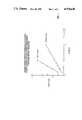
- FIG. 1shows, for a three-fin heat sink, an empirically developed plot of temperature rise of a plastic packaged circuit chip versus power dissipation of that circuit chip. Temperature rise from the upper surface of a plastic package (case) to the module ambient (air) is plotted on the vertical axis as a function of the power dissipation of the circuit chip on the horizontal axis. Comparison of the two plots indicates increased power handling capability for the same temperature differential when the plastic package is enhanced with a three-fin heat sink. This increase in power dissipation relates directly to an increase in performance, function, and reliability.
- FIG. 2exemplifies conventional surface mount plastic package heat sinks.
- a leaded component(not visible) is packaged in molded plastic housing 4, also known as a flat pack.
- Component leads 6extend from housing 4, which is typically formed by joining two separately molded members 8 and 10 at the interface indicated by dotted line 12.
- Interface material 14typically thermal glue or epoxy, is sized to conform to the upper planar surface 16 of housing 4.
- An extruded finned heat sink 18is retained in heat conducting relation to component housing 4 by interface material 14.
- thermal enhancement techniqueOne difficulty with such a thermal enhancement technique is the attendant requirement for special tooling to accurately align and orient the heat sink and interface material with respect to the component during epoxy curing operation(s) in order to avoid any misalignment which would have a negative impact on efficient utilization of the thermal enhancement.
- epoxyis difficult to handle in a rework environment since it forms a strong bond the breaking of which increases the chances of damage to the assembly.
- thermal greasemay be used as the interface material.
- a thermal greasestill must be applied to one of the two mating surfaces, and its use induces alignment problems since it does not "set".
- thermal greaseis very reworkable, it is not stable. This feature implies that a slip could occur between the two bonded surfaces which would reduce the effectiveness of the enhancement.
- Thermal greasecould leak out if not adequately confined; and its material properties may change with time creating a material interface not representative of initial design requirements.
- IBM Technical Disclosure Bulletin, Vol. 22, No. 3, 8/79. p. 960 to DeMaine et aldescribes a field removable, replaceable, and reusable heat sink. Attachment of the heat sink to the module is accomplished by means of a heat or chemically shrinkable plastic collar.
- IBM Technical Disclosure Bulletin, Vol. 28, No. 12, 5/86. p. 5172 to Lee et aldiscloses a heat sink adapted for attachment to a module with a spring clip.
- the present inventionovercomes the difficulties associated with adapting prior art thermal enhancement techniques to plastic circuit packaging by molding features into the plastic cover so as to readily mate with a complementarily configured heat sink.
- the plastic package and heat sinkare configured during molding and/or extrusion forming steps to mate together and includes an interface material between them when assembled.
- the heat sink and plastic packageare configured to snap into mating engagement without a need for interface material therebetween. Either embodiment may be implemented using automated material handling techniques.
- the present inventionis described below as implemented in a molded plastic package for an integrated circuit chip.
- Incorporated in the upper section of the plastic packageis a portion of an improved attachment mechanism for a heat sink.
- a convective heat sinkis removably mounted to the top of the molded plastic package, through engagement with matingly configured features molded into or attached to the top surface of the package.
- Providing heat sink element receiving members on the packageallows attachment of a heat sink yielding a thermally enhanced package, optimized for placement, orientation, attachment, and assembly procedures.
- the present inventionadditionally facilitates both greater reworkability of and optimized power dissipation from the circuit chip.
- FIG. 1is a graphic representation of a comparison of thermal characteristics of a plastic chip package with and without thermal enhancement
- FIG. 2is an exploded view of a conventional heat sink apparatus for surface mount plastic packages
- FIG. 3is an exploded, perspective view of a first embodiment of the invention.
- FIG. 4is an exploded, perspective view of another embodiment of the invention.
- the present inventionfinds particular utility with high power components such as microprocessors.
- high power componentssuch as microprocessors.
- Currently such devicesare available in plastic flatpacks which are generally square.
- FIG. 3a perspective view of a plastic chip package 4 is shown with surface 16 of its top section 8 modified in accordance with our invention to accept a typical heat sink 18.
- the modification of surface 16 shown in FIG. 3results in a raised ridge or flange 20, around the upper perimeter of housing section 8, which forms an indentation or cavity 24 surrounded by flange 20 on top surface 16 of plastic package 4.
- a plastic package 4 provided with the surface configuration shown in FIG. 3is assembled to a circuit card (not shown) in accordance with conventional electronic card assembly manufacturing processes.
- Thermally conductive interface material 14, sized to conform to the exposed area of surface 16 within flange 20is placed therein, followed by heat sink 18.
- Cavity 24serves the purpose of insuring that heat sink 18 is properly oriented and aligned on plastic circuit package 4 and is not subject to being dislodged during subsequent process steps. Such necessary steps include curing interface material 14. Flange 20 further insures that heat sink 18 is placed in the same orientation as plastic package 4, substantially eliminating skewing of the heat sink 18 by handling or vibration.
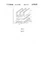
- FIG. 4an embodiment of the invention is described which enhances assembly and rework capability.
- An exploded perspective viewis shown with top surface 16 of plastic chip package 4 modified by a clip element 28 form around all four edges of top section 10 of package 4.
- Fingers 30 of clip 28are molded so as to matingly engage with grooves 34 which have been extruded, molded or machined into the side surfaces of heat sink 36.
- Proper alignment of heat sink 36 with respect to the orientation of plastic circuit package 4is assured.
- the reworkability of the packageis optimized by the ease in which the heat sink can be removed from the plastic chip package.
- the attachment technique shown in FIG. 4increases the capability of using the same plastic chip package for various air cooled machines.
- different heat sink designse.g., no. of fins, fin spacing, fin heights, etc.
- the same componentmay be optimized for operation in other electronic systems with different cooling flow rates.
- heat sink configuration 36that is with only two sides thereof having grooves to engage clip 28, allows the same heat sink - plastic package combination to be used in situations with different air flow patterns and directions. Even after being rotated 90 degrees, heat sink 36 may still be snap fit into the other pair of opposed, parallel clip 28 legs.
Landscapes
- Physics & Mathematics (AREA)
- Condensed Matter Physics & Semiconductors (AREA)
- General Physics & Mathematics (AREA)
- Engineering & Computer Science (AREA)
- Computer Hardware Design (AREA)
- Microelectronics & Electronic Packaging (AREA)
- Power Engineering (AREA)
- Cooling Or The Like Of Semiconductors Or Solid State Devices (AREA)
Abstract
Description
1. Field of the lnvention
This invention relates to cooling integrated circuit chip packages and more particularly it relates to improved convective cooling of high power devices in molded plastic packages.
2. Prior Art
Various heat sinking configurations for the enhancement of integrated circuit chip packages are known. In many instances, additional spring clamps are used to assist in the assembly of the heat sink to the circuit package. Clamps require additional parts with their associated costs and increased handling and inventory overhead. A spring/clamp attach technique also fails to reduce potential thermal interface problems which may occur when two non-flat surfaces are mated together. This interface mismatch increases the thermal resistance to heat flow and, thus, reduces the amount of power that can be dissipated by the assembled heat sink.
Available techniques to reduce the above noted interface thermal resistance problem include the utilization of a material such as a thermal grease or a thermal epoxy between the circuit package and the thermal enhancement (heat sink).
Results obtained from characterizing bonded heat sink components indicate that a heat sink sufficiently enhances the power handling capability of the circuit package. FIG. 1 shows, for a three-fin heat sink, an empirically developed plot of temperature rise of a plastic packaged circuit chip versus power dissipation of that circuit chip. Temperature rise from the upper surface of a plastic package (case) to the module ambient (air) is plotted on the vertical axis as a function of the power dissipation of the circuit chip on the horizontal axis. Comparison of the two plots indicates increased power handling capability for the same temperature differential when the plastic package is enhanced with a three-fin heat sink. This increase in power dissipation relates directly to an increase in performance, function, and reliability.
FIG. 2 exemplifies conventional surface mount plastic package heat sinks. A leaded component (not visible) is packaged in molded plastic housing 4, also known as a flat pack. Component leads 6 extend from housing 4, which is typically formed by joining two separately moldedmembers dotted line 12.
One difficulty with such a thermal enhancement technique is the attendant requirement for special tooling to accurately align and orient the heat sink and interface material with respect to the component during epoxy curing operation(s) in order to avoid any misalignment which would have a negative impact on efficient utilization of the thermal enhancement.
Further, epoxy is difficult to handle in a rework environment since it forms a strong bond the breaking of which increases the chances of damage to the assembly.
Some of these problems may be solved with the use of a non-curing thermal grease as the interface material. However, a thermal grease still must be applied to one of the two mating surfaces, and its use induces alignment problems since it does not "set". Although thermal grease is very reworkable, it is not stable. This feature implies that a slip could occur between the two bonded surfaces which would reduce the effectiveness of the enhancement. Thermal grease could leak out if not adequately confined; and its material properties may change with time creating a material interface not representative of initial design requirements.
Prior art heat dissipation methods are adequate so long as circuit package design and spacing constraints are such that an additional spring assembly can be incorporated into the product design. When the assembly procedure is such that a curing cycle does not add unacceptable expense in the form of additional ovens, floor space, utility consumption, material handling, etc., the use of epoxy bond is acceptable. If material stability is not a problem, then thermal grease interface techniques may be used.
There exists, therefore, a need for an efficient, cost effective, reworkable thermal enhancement arrangement for enabling use of high power devices in low end systems.
IBM Technical Disclosure Bulletin, Vol. 22, No. 3, 8/79. p. 960 to DeMaine et al describes a field removable, replaceable, and reusable heat sink. Attachment of the heat sink to the module is accomplished by means of a heat or chemically shrinkable plastic collar. IBM Technical Disclosure Bulletin, Vol. 28, No. 12, 5/86. p. 5172 to Lee et al discloses a heat sink adapted for attachment to a module with a spring clip.
IBM Technical Disclosure Bulletin, Vol. 28, No. 12, 5/86. p. 5531 to Curtis et al discloses a technique for thermally enhancing plastic packaged modules by bonding ceramic to the device lead frame prior to encapsulation.
Presently, it is desirable to use automated assembly procedures with reduced assembly operations. Included in such procedures is an additional desire to stock minimum parts, and to have a reworkable enhancement assembly technique which performs uniformly with respect to the lifetime of the circuit package. In this case prior art circuit package thermal enhancement attachment techniques are inadequate.
Accordingly, it is an object of this invention to provide an improved, simplified attachment technique for the assembly of a reworkable convective heat sink to a circuit package.
It is a further object of the present invention to attach the convective heat sink to a circuit package without introducing new materials and/or processes to the assembly operation.
It is a still further object of this invention to provide an assembly technique that is not restricted to a single convective heat sink design.
It is still another object of this invention to insure that the convective heat sink is correctly oriented with respect to the orientation of the circuit package and the cooling flow.
The present invention overcomes the difficulties associated with adapting prior art thermal enhancement techniques to plastic circuit packaging by molding features into the plastic cover so as to readily mate with a complementarily configured heat sink. In one embodiment the plastic package and heat sink are configured during molding and/or extrusion forming steps to mate together and includes an interface material between them when assembled. In another embodiment the heat sink and plastic package are configured to snap into mating engagement without a need for interface material therebetween. Either embodiment may be implemented using automated material handling techniques.
The present invention is described below as implemented in a molded plastic package for an integrated circuit chip. Incorporated in the upper section of the plastic package is a portion of an improved attachment mechanism for a heat sink. A convective heat sink is removably mounted to the top of the molded plastic package, through engagement with matingly configured features molded into or attached to the top surface of the package.
Providing heat sink element receiving members on the package allows attachment of a heat sink yielding a thermally enhanced package, optimized for placement, orientation, attachment, and assembly procedures. The present invention additionally facilitates both greater reworkability of and optimized power dissipation from the circuit chip.
The above and other features and advantages of the present invention will be described having reference to the accompanying drawing, wherein like reference numerals are used throughout to designate the same elements and wherein:
FIG. 1 is a graphic representation of a comparison of thermal characteristics of a plastic chip package with and without thermal enhancement;
FIG. 2 is an exploded view of a conventional heat sink apparatus for surface mount plastic packages;
FIG. 3 is an exploded, perspective view of a first embodiment of the invention; and
FIG. 4 is an exploded, perspective view of another embodiment of the invention.
The present invention finds particular utility with high power components such as microprocessors. Currently such devices are available in plastic flatpacks which are generally square.
Referring now to FIG. 3, a perspective view of a plastic chip package 4 is shown withsurface 16 of itstop section 8 modified in accordance with our invention to accept atypical heat sink 18. The modification ofsurface 16 shown in FIG. 3 results in a raised ridge orflange 20, around the upper perimeter ofhousing section 8, which forms an indentation orcavity 24 surrounded byflange 20 ontop surface 16 of plastic package 4.
In operation, a plastic package 4 provided with the surface configuration shown in FIG. 3 is assembled to a circuit card (not shown) in accordance with conventional electronic card assembly manufacturing processes. Thermallyconductive interface material 14, sized to conform to the exposed area ofsurface 16 withinflange 20 is placed therein, followed byheat sink 18.
Referring now to FIG. 4, an embodiment of the invention is described which enhances assembly and rework capability. An exploded perspective view is shown withtop surface 16 of plastic chip package 4 modified by aclip element 28 form around all four edges oftop section 10 of package 4.Fingers 30 ofclip 28 are molded so as to matingly engage withgrooves 34 which have been extruded, molded or machined into the side surfaces ofheat sink 36. There is no need for an interface material. Proper alignment ofheat sink 36 with respect to the orientation of plastic circuit package 4 is assured. In addition, the reworkability of the package is optimized by the ease in which the heat sink can be removed from the plastic chip package.
The attachment technique shown in FIG. 4 increases the capability of using the same plastic chip package for various air cooled machines. By use of different heat sink designs (e.g., no. of fins, fin spacing, fin heights, etc.) the same component may be optimized for operation in other electronic systems with different cooling flow rates.
Further,heat sink configuration 36, that is with only two sides thereof having grooves to engageclip 28, allows the same heat sink - plastic package combination to be used in situations with different air flow patterns and directions. Even after being rotated 90 degrees,heat sink 36 may still be snap fit into the other pair of opposed,parallel clip 28 legs.
While the present invention has been described having reference to a preferred embodiment and modifications thereto, those having skill in the art will appreciate that practice of our invention is not limited to the heat sink design used only for illustrative purposes. Alterations to the design of the molded change to the top surface of the plastic chip package to accommodate other heat sink designs needed to meet other cooling requirements (e.g., circular fins, pin fins, etc.) and still other changes in form and detail may be made without departing from the spirit and scope of our invention as described in the following claims.
Claims (7)
1. A method of thermally enhancing a rectangular plastic packaged electronic component comprising the steps of:
providing a first member of a pair of complementary matingly engageable elements on an upper planar surface of said component and a second member of said pair of engageable elements on bottom edges of a heat sink; and
joining said component and heat sink.
2. The method of claim 1 including an additional step between said providing and joining steps comprising:
inserting an appropriately dimensioned layer of heat conductive interface material between said component and said heat sink.
3. The method of claims 1 or 2 wherein said providing steps includes:
molding integral with said plastic package a lip around its perimeter on its upper planar surface for defining a cavity having dimensions adapted for receiving said second member of said pair of snap engageable members on said heat sink.
4. The method of claims 1 or 2 wherein said providing step includes:
adding on inwardly extending flange around all edges of said upper planar surface of said plastic packaged component; and
forming in said heat sink a pair of grooves, one on each of two parallel sides, adapted for snap engagement with said parallel flanges on said plastic packaged component.
5. A method of attaching an extruded metal heat sink element to a square plastic packaged electronic device on its upper planar surface comprising:
adding on inwardly extending flange around all edges of said upper planar surface of said plastic packaged component;
forming in said heat sink a pair of grooves, one on each of two parallel sides, adapted for snap engagement with either set of parallel flanges on said plastic packaged device; and
joining said device and said heat sink.
6. The method of claim 5 wherein said adding step is performed as an integral step in molding said plastic package.
7. The methods of claim 5 or 6 including the additional step, preceding said joining step of placing conformingly dimensioned thermally conductive interface material on said device inside said inwardly extending flange.
Priority Applications (3)
| Application Number | Priority Date | Filing Date | Title |
|---|---|---|---|
| US07/454,655US4978638A (en) | 1989-12-21 | 1989-12-21 | Method for attaching heat sink to plastic packaged electronic component |
| JP2313010AJPH0642519B2 (en) | 1989-12-21 | 1990-11-20 | Plastic chip / chip circuit package, electronic component heat dissipation enhancement method, heat sink element mounting method |
| EP90313539AEP0434298A1 (en) | 1989-12-21 | 1990-12-12 | Thermally enhanced electronic component package |
Applications Claiming Priority (1)
| Application Number | Priority Date | Filing Date | Title |
|---|---|---|---|
| US07/454,655US4978638A (en) | 1989-12-21 | 1989-12-21 | Method for attaching heat sink to plastic packaged electronic component |
Publications (1)
| Publication Number | Publication Date |
|---|---|
| US4978638Atrue US4978638A (en) | 1990-12-18 |
Family
ID=23805525
Family Applications (1)
| Application Number | Title | Priority Date | Filing Date |
|---|---|---|---|
| US07/454,655Expired - Fee RelatedUS4978638A (en) | 1989-12-21 | 1989-12-21 | Method for attaching heat sink to plastic packaged electronic component |
Country Status (3)
| Country | Link |
|---|---|
| US (1) | US4978638A (en) |
| EP (1) | EP0434298A1 (en) |
| JP (1) | JPH0642519B2 (en) |
Cited By (56)
| Publication number | Priority date | Publication date | Assignee | Title |
|---|---|---|---|---|
| WO1989003264A1 (en)* | 1987-10-16 | 1989-04-20 | Avco Corporation | High temperature metal alloy mixtures for filling holes and repairing damages in superalloy bodies |
| US5099550A (en)* | 1990-11-05 | 1992-03-31 | Mi Proprietary | Clamp for attachment of a heat sink |
| US5155579A (en)* | 1991-02-05 | 1992-10-13 | Advanced Micro Devices | Molded heat sink for integrated circuit package |
| US5299632A (en)* | 1993-02-19 | 1994-04-05 | Lee Lien Jung | Fin device for an integrated circuit |
| US5307239A (en)* | 1992-10-08 | 1994-04-26 | Unisys Corporation | Electromechanical module with small footprint and post-solder attachable/removable heat sink frame |
| US5329426A (en)* | 1993-03-22 | 1994-07-12 | Digital Equipment Corporation | Clip-on heat sink |
| US5335143A (en)* | 1993-08-05 | 1994-08-02 | International Business Machines Corporation | Disk augmented heat transfer system |
| WO1994019594A1 (en)* | 1993-02-26 | 1994-09-01 | Lsi Logic Corporation | High power dissipating packages with matched heatspreader heatsink assemblies |
| US5350713A (en)* | 1990-12-19 | 1994-09-27 | Vlsi Technology, Inc. | Design and sealing method for semiconductor packages |
| EP0619605A1 (en)* | 1993-04-05 | 1994-10-12 | STMicroelectronics S.r.l. | Combination of an electronic semiconductor device and a heat sink |
| US5473511A (en)* | 1994-05-05 | 1995-12-05 | Ford Motor Company | Printed circuit board with high heat dissipation |
| US5650593A (en)* | 1994-05-26 | 1997-07-22 | Amkor Electronics, Inc. | Thermally enhanced chip carrier package |
| US5827999A (en)* | 1994-05-26 | 1998-10-27 | Amkor Electronics, Inc. | Homogeneous chip carrier package |
| US5926370A (en)* | 1998-10-29 | 1999-07-20 | Hewlett-Packard Company | Method and apparatus for a modular integrated apparatus for multi-function components |
| US6061235A (en)* | 1998-11-18 | 2000-05-09 | Hewlett-Packard Company | Method and apparatus for a modular integrated apparatus for heat dissipation, processor integration, electrical interface, and electromagnetic interference management |
| US6084178A (en)* | 1998-02-27 | 2000-07-04 | Hewlett-Packard Company | Perimeter clamp for mounting and aligning a semiconductor component as part of a field replaceable unit (FRU) |
| US6093961A (en)* | 1999-02-24 | 2000-07-25 | Chip Coolers, Inc. | Heat sink assembly manufactured of thermally conductive polymer material with insert molded metal attachment |
| US6176304B1 (en)* | 1998-11-24 | 2001-01-23 | Hon Hai Precision Ind. Co., Ltd. | Heat sink |
| US6198630B1 (en) | 1999-01-20 | 2001-03-06 | Hewlett-Packard Company | Method and apparatus for electrical and mechanical attachment, and electromagnetic interference and thermal management of high speed, high density VLSI modules |
| US6219238B1 (en) | 1999-05-10 | 2001-04-17 | International Business Machines Corporation | Structure for removably attaching a heat sink to surface mount packages |
| US6248199B1 (en) | 1999-04-26 | 2001-06-19 | Soundcraft, Inc. | Method for the continuous fabrication of access control and identification cards with embedded electronics or other elements |
| US6364670B1 (en)* | 1998-11-18 | 2002-04-02 | Robert Bosch Corporation | Junction box having function electronics |
| EP1198000A1 (en)* | 1994-04-28 | 2002-04-17 | Fujitsu Limited | Semiconductor device and assembly board |
| US6386274B1 (en)* | 2001-06-28 | 2002-05-14 | Foxconn Precision Components Co., Ltd. | Heat sink assembly |
| US6456515B1 (en) | 2000-11-27 | 2002-09-24 | Briggs & Stratton Corporation | Three-phase H-bridge assembly and method of assembling the same |
| US20030173942A1 (en)* | 2002-02-07 | 2003-09-18 | Cooligy, Inc. | Apparatus for conditioning power and managing thermal energy in an electronic device |
| US20030194483A1 (en)* | 2002-04-12 | 2003-10-16 | International Business Machines Corporation | Grease rework applicator |
| US6639803B1 (en) | 2002-07-11 | 2003-10-28 | International Business Machines Corporation | Compliant heat sink device/mounting system interconnect and a method of implementing same |
| US6781837B2 (en)* | 2002-12-06 | 2004-08-24 | Dell Products L.P. | System and method for information handling system heat sink retention |
| US20040188064A1 (en)* | 2002-11-01 | 2004-09-30 | Cooligy Inc. | Channeled flat plate fin heat exchange system, device and method |
| US20040188065A1 (en)* | 2003-01-31 | 2004-09-30 | Cooligy, Inc. | Decoupled spring-loaded mounting apparatus and method of manufacturing thereof |
| US20040201964A1 (en)* | 2002-11-20 | 2004-10-14 | Sigl Dennis R. | Snap-in heat sink for semiconductor mounting |
| WO2004070304A3 (en)* | 2003-01-31 | 2005-01-06 | Cooligy Inc | Removeable heat spreader support mechanism and method of manufacturing thereof |
| US20050022970A1 (en)* | 2003-07-31 | 2005-02-03 | Mania Michael John | Wrap around heat sink apparatus and method |
| US20050084385A1 (en)* | 2002-09-23 | 2005-04-21 | David Corbin | Micro-fabricated electrokinetic pump |
| US6890202B2 (en)* | 1999-12-28 | 2005-05-10 | J.S.T. Mfg. Co., Ltd. | Connector for module |
| US20050183445A1 (en)* | 2003-01-31 | 2005-08-25 | Mark Munch | Remedies to prevent cracking in a liquid system |
| US20050211418A1 (en)* | 2002-11-01 | 2005-09-29 | Cooligy, Inc. | Method and apparatus for efficient vertical fluid delivery for cooling a heat producing device |
| US20050269061A1 (en)* | 2004-06-04 | 2005-12-08 | Cooligy, Inc. | Apparatus and method of efficient fluid delivery for cooling a heat producing device |
| US20050270742A1 (en)* | 2004-06-04 | 2005-12-08 | Cooligy, Inc. | Semi-compliant joining mechanism for semiconductor cooling applications |
| US20070086170A1 (en)* | 2005-10-18 | 2007-04-19 | Hon Hai Precision Industry Co., Ltd. | Heat sink device with shielding member |
| US20080310117A1 (en)* | 2007-03-05 | 2008-12-18 | International Business Machines Corporation | Method and structure to improve thermal dissipation from semiconductor devices |
| US7539020B2 (en) | 2006-02-16 | 2009-05-26 | Cooligy Inc. | Liquid cooling loops for server applications |
| US7616444B2 (en) | 2004-06-04 | 2009-11-10 | Cooligy Inc. | Gimballed attachment for multiple heat exchangers |
| US7660117B2 (en) | 2007-08-07 | 2010-02-09 | Cooligy Inc. | Deformable duct guides that accommodate electronic connection lines |
| US7715194B2 (en) | 2006-04-11 | 2010-05-11 | Cooligy Inc. | Methodology of cooling multiple heat sources in a personal computer through the use of multiple fluid-based heat exchanging loops coupled via modular bus-type heat exchangers |
| US7836597B2 (en) | 2002-11-01 | 2010-11-23 | Cooligy Inc. | Method of fabricating high surface to volume ratio structures and their integration in microheat exchangers for liquid cooling system |
| US7922364B2 (en) | 2009-03-10 | 2011-04-12 | Osram Sylvania, Inc. | LED lamp assembly |
| CN101754667B (en)* | 2008-12-22 | 2011-11-09 | 永硕联合国际股份有限公司 | Electromagnetic shielding device with heat dissipation function |
| US8157001B2 (en) | 2006-03-30 | 2012-04-17 | Cooligy Inc. | Integrated liquid to air conduction module |
| US8254422B2 (en) | 2008-08-05 | 2012-08-28 | Cooligy Inc. | Microheat exchanger for laser diode cooling |
| US8250877B2 (en) | 2008-03-10 | 2012-08-28 | Cooligy Inc. | Device and methodology for the removal of heat from an equipment rack by means of heat exchangers mounted to a door |
| US8602092B2 (en) | 2003-07-23 | 2013-12-10 | Cooligy, Inc. | Pump and fan control concepts in a cooling system |
| US9297571B1 (en) | 2008-03-10 | 2016-03-29 | Liebert Corporation | Device and methodology for the removal of heat from an equipment rack by means of heat exchangers mounted to a door |
| US11322423B2 (en)* | 2018-03-26 | 2022-05-03 | Hitachi Astemo, Ltd. | Electronic control device |
| US20220394876A1 (en)* | 2020-02-14 | 2022-12-08 | Denso Corporation | Power controller apparatus |
Families Citing this family (6)
| Publication number | Priority date | Publication date | Assignee | Title |
|---|---|---|---|---|
| US5146981A (en)* | 1991-11-14 | 1992-09-15 | Digital Equipment Corporation | Substrate to heatsink interface apparatus and method |
| JPH05326771A (en)* | 1992-05-26 | 1993-12-10 | Gurafuiko:Kk | Heat radiator mounting structure for electronic device |
| IL149814A0 (en)* | 1999-11-22 | 2002-11-10 | Univ Illinois | Active package for integrated circuit |
| DE102004043019A1 (en) | 2004-09-06 | 2006-03-23 | eupec Europäische Gesellschaft für Leistungshalbleiter mbH | module |
| JP4640183B2 (en)* | 2006-01-16 | 2011-03-02 | 三菱電機株式会社 | Heat exchanger |
| CN101616570B (en)* | 2008-06-25 | 2012-07-04 | 富准精密工业(深圳)有限公司 | Protective cover |
Citations (10)
| Publication number | Priority date | Publication date | Assignee | Title |
|---|---|---|---|---|
| US3893161A (en)* | 1974-02-04 | 1975-07-01 | Jr Albert Pesak | Frictionally engageable heat sink for solid state devices |
| US4012769A (en)* | 1975-08-04 | 1977-03-15 | Thermalloy Incorporated | Heat sink with parallel flat faces |
| US4041524A (en)* | 1974-12-30 | 1977-08-09 | The Staver Company, Inc. | Heat dissipating device for transistor with outwardly extending heat conductive tab |
| US4107555A (en)* | 1976-03-05 | 1978-08-15 | Robert Bosch Gmbh | Proximity switch and circuit system |
| US4203488A (en)* | 1978-03-01 | 1980-05-20 | Aavid Engineering, Inc. | Self-fastened heat sinks |
| US4222090A (en)* | 1977-11-25 | 1980-09-09 | Jaffe Richard A | Micromodular electronic package |
| US4235285A (en)* | 1979-10-29 | 1980-11-25 | Aavid Engineering, Inc. | Self-fastened heat sinks |
| US4408220A (en)* | 1981-01-29 | 1983-10-04 | Calabro Anthony Denis | Heat dissipator for a dual in line integrated circuit package |
| US4552206A (en)* | 1983-01-17 | 1985-11-12 | Aavid Engineering, Inc. | Heat sinks for integrated circuit modules |
| JPS6471154A (en)* | 1987-09-11 | 1989-03-16 | Mitsubishi Electric Corp | Method of mounting heat sink |
Family Cites Families (5)
| Publication number | Priority date | Publication date | Assignee | Title |
|---|---|---|---|---|
| JPS4852379A (en)* | 1971-11-01 | 1973-07-23 | ||
| FR2580137A1 (en)* | 1985-04-05 | 1986-10-10 | Omron Tateisi Electronics Co | Assembly of electronic components |
| JPS6258045U (en)* | 1985-09-30 | 1987-04-10 | ||
| JPS64339U (en)* | 1987-06-19 | 1989-01-05 | ||
| JPH0189789U (en)* | 1987-12-04 | 1989-06-13 |
- 1989
- 1989-12-21USUS07/454,655patent/US4978638A/ennot_activeExpired - Fee Related
- 1990
- 1990-11-20JPJP2313010Apatent/JPH0642519B2/ennot_activeExpired - Lifetime
- 1990-12-12EPEP90313539Apatent/EP0434298A1/ennot_activeWithdrawn
Patent Citations (10)
| Publication number | Priority date | Publication date | Assignee | Title |
|---|---|---|---|---|
| US3893161A (en)* | 1974-02-04 | 1975-07-01 | Jr Albert Pesak | Frictionally engageable heat sink for solid state devices |
| US4041524A (en)* | 1974-12-30 | 1977-08-09 | The Staver Company, Inc. | Heat dissipating device for transistor with outwardly extending heat conductive tab |
| US4012769A (en)* | 1975-08-04 | 1977-03-15 | Thermalloy Incorporated | Heat sink with parallel flat faces |
| US4107555A (en)* | 1976-03-05 | 1978-08-15 | Robert Bosch Gmbh | Proximity switch and circuit system |
| US4222090A (en)* | 1977-11-25 | 1980-09-09 | Jaffe Richard A | Micromodular electronic package |
| US4203488A (en)* | 1978-03-01 | 1980-05-20 | Aavid Engineering, Inc. | Self-fastened heat sinks |
| US4235285A (en)* | 1979-10-29 | 1980-11-25 | Aavid Engineering, Inc. | Self-fastened heat sinks |
| US4408220A (en)* | 1981-01-29 | 1983-10-04 | Calabro Anthony Denis | Heat dissipator for a dual in line integrated circuit package |
| US4552206A (en)* | 1983-01-17 | 1985-11-12 | Aavid Engineering, Inc. | Heat sinks for integrated circuit modules |
| JPS6471154A (en)* | 1987-09-11 | 1989-03-16 | Mitsubishi Electric Corp | Method of mounting heat sink |
Non-Patent Citations (6)
| Title |
|---|
| S. A. Curtis et al., "Surface Mount Chip Packaging", IBM Technical Disclosure Bulletin, vol. 28, No. 12, May, 1986, pp. 5531-5532. |
| S. A. Curtis et al., Surface Mount Chip Packaging , IBM Technical Disclosure Bulletin, vol. 28, No. 12, May, 1986, pp. 5531 5532.* |
| S. W. Lee et al., "Low Profile Heat Sink", IBM Technical Disclosure Bulletin, vol. 28, No. 12, May, 1986, pp. 5172-5173. |
| S. W. Lee et al., Low Profile Heat Sink , IBM Technical Disclosure Bulletin, vol. 28, No. 12, May, 1986, pp. 5172 5173.* |
| T. J. Demaine et al., "Attachable heat Sink for Pluggable Modules", IBM Technical Disclosure Bulletin, vol. 22, No. 3, 8/79, 00/960-961 |
| T. J. Demaine et al., Attachable heat Sink for Pluggable Modules , IBM Technical Disclosure Bulletin, vol. 22, No. 3, 8/79, 00/960 961* |
Cited By (82)
| Publication number | Priority date | Publication date | Assignee | Title |
|---|---|---|---|---|
| WO1989003264A1 (en)* | 1987-10-16 | 1989-04-20 | Avco Corporation | High temperature metal alloy mixtures for filling holes and repairing damages in superalloy bodies |
| US5099550A (en)* | 1990-11-05 | 1992-03-31 | Mi Proprietary | Clamp for attachment of a heat sink |
| US5350713A (en)* | 1990-12-19 | 1994-09-27 | Vlsi Technology, Inc. | Design and sealing method for semiconductor packages |
| US5155579A (en)* | 1991-02-05 | 1992-10-13 | Advanced Micro Devices | Molded heat sink for integrated circuit package |
| US5307239A (en)* | 1992-10-08 | 1994-04-26 | Unisys Corporation | Electromechanical module with small footprint and post-solder attachable/removable heat sink frame |
| US5299632A (en)* | 1993-02-19 | 1994-04-05 | Lee Lien Jung | Fin device for an integrated circuit |
| WO1994019594A1 (en)* | 1993-02-26 | 1994-09-01 | Lsi Logic Corporation | High power dissipating packages with matched heatspreader heatsink assemblies |
| US5353193A (en)* | 1993-02-26 | 1994-10-04 | Lsi Logic Corporation | High power dissipating packages with matched heatspreader heatsink assemblies |
| US5463529A (en)* | 1993-02-26 | 1995-10-31 | Lsi Logic Corporation | High power dissipating packages with matched heatspreader heatsink assemblies |
| US5329426A (en)* | 1993-03-22 | 1994-07-12 | Digital Equipment Corporation | Clip-on heat sink |
| EP0619605A1 (en)* | 1993-04-05 | 1994-10-12 | STMicroelectronics S.r.l. | Combination of an electronic semiconductor device and a heat sink |
| US5521439A (en)* | 1993-04-05 | 1996-05-28 | Sgs-Microelectronics S.R.L. | Combination and method for coupling a heat sink to a semiconductor device |
| US5335143A (en)* | 1993-08-05 | 1994-08-02 | International Business Machines Corporation | Disk augmented heat transfer system |
| EP1198000A1 (en)* | 1994-04-28 | 2002-04-17 | Fujitsu Limited | Semiconductor device and assembly board |
| US5473511A (en)* | 1994-05-05 | 1995-12-05 | Ford Motor Company | Printed circuit board with high heat dissipation |
| US5650593A (en)* | 1994-05-26 | 1997-07-22 | Amkor Electronics, Inc. | Thermally enhanced chip carrier package |
| US5827999A (en)* | 1994-05-26 | 1998-10-27 | Amkor Electronics, Inc. | Homogeneous chip carrier package |
| US6084178A (en)* | 1998-02-27 | 2000-07-04 | Hewlett-Packard Company | Perimeter clamp for mounting and aligning a semiconductor component as part of a field replaceable unit (FRU) |
| US5926370A (en)* | 1998-10-29 | 1999-07-20 | Hewlett-Packard Company | Method and apparatus for a modular integrated apparatus for multi-function components |
| US6364670B1 (en)* | 1998-11-18 | 2002-04-02 | Robert Bosch Corporation | Junction box having function electronics |
| US6061235A (en)* | 1998-11-18 | 2000-05-09 | Hewlett-Packard Company | Method and apparatus for a modular integrated apparatus for heat dissipation, processor integration, electrical interface, and electromagnetic interference management |
| US6176304B1 (en)* | 1998-11-24 | 2001-01-23 | Hon Hai Precision Ind. Co., Ltd. | Heat sink |
| US6198630B1 (en) | 1999-01-20 | 2001-03-06 | Hewlett-Packard Company | Method and apparatus for electrical and mechanical attachment, and electromagnetic interference and thermal management of high speed, high density VLSI modules |
| US6093961A (en)* | 1999-02-24 | 2000-07-25 | Chip Coolers, Inc. | Heat sink assembly manufactured of thermally conductive polymer material with insert molded metal attachment |
| US6248199B1 (en) | 1999-04-26 | 2001-06-19 | Soundcraft, Inc. | Method for the continuous fabrication of access control and identification cards with embedded electronics or other elements |
| US6219238B1 (en) | 1999-05-10 | 2001-04-17 | International Business Machines Corporation | Structure for removably attaching a heat sink to surface mount packages |
| US6890202B2 (en)* | 1999-12-28 | 2005-05-10 | J.S.T. Mfg. Co., Ltd. | Connector for module |
| US6456515B1 (en) | 2000-11-27 | 2002-09-24 | Briggs & Stratton Corporation | Three-phase H-bridge assembly and method of assembling the same |
| US6386274B1 (en)* | 2001-06-28 | 2002-05-14 | Foxconn Precision Components Co., Ltd. | Heat sink assembly |
| US7061104B2 (en) | 2002-02-07 | 2006-06-13 | Cooligy, Inc. | Apparatus for conditioning power and managing thermal energy in an electronic device |
| US7050308B2 (en) | 2002-02-07 | 2006-05-23 | Cooligy, Inc. | Power conditioning module |
| US20030173942A1 (en)* | 2002-02-07 | 2003-09-18 | Cooligy, Inc. | Apparatus for conditioning power and managing thermal energy in an electronic device |
| US20040240245A1 (en)* | 2002-02-07 | 2004-12-02 | Cooligy, Inc. | Power conditioning module |
| US20030194483A1 (en)* | 2002-04-12 | 2003-10-16 | International Business Machines Corporation | Grease rework applicator |
| US6881265B2 (en)* | 2002-04-12 | 2005-04-19 | International Business Machines Corporation | Grease rework applicator |
| US6639803B1 (en) | 2002-07-11 | 2003-10-28 | International Business Machines Corporation | Compliant heat sink device/mounting system interconnect and a method of implementing same |
| US20050084385A1 (en)* | 2002-09-23 | 2005-04-21 | David Corbin | Micro-fabricated electrokinetic pump |
| US7449122B2 (en) | 2002-09-23 | 2008-11-11 | Cooligy Inc. | Micro-fabricated electrokinetic pump |
| US20050211418A1 (en)* | 2002-11-01 | 2005-09-29 | Cooligy, Inc. | Method and apparatus for efficient vertical fluid delivery for cooling a heat producing device |
| US7806168B2 (en) | 2002-11-01 | 2010-10-05 | Cooligy Inc | Optimal spreader system, device and method for fluid cooled micro-scaled heat exchange |
| US20040188064A1 (en)* | 2002-11-01 | 2004-09-30 | Cooligy Inc. | Channeled flat plate fin heat exchange system, device and method |
| US6988535B2 (en) | 2002-11-01 | 2006-01-24 | Cooligy, Inc. | Channeled flat plate fin heat exchange system, device and method |
| US7836597B2 (en) | 2002-11-01 | 2010-11-23 | Cooligy Inc. | Method of fabricating high surface to volume ratio structures and their integration in microheat exchangers for liquid cooling system |
| US20040201964A1 (en)* | 2002-11-20 | 2004-10-14 | Sigl Dennis R. | Snap-in heat sink for semiconductor mounting |
| US6781837B2 (en)* | 2002-12-06 | 2004-08-24 | Dell Products L.P. | System and method for information handling system heat sink retention |
| US20050183845A1 (en)* | 2003-01-31 | 2005-08-25 | Mark Munch | Remedies to prevent cracking in a liquid system |
| US20050210913A1 (en)* | 2003-01-31 | 2005-09-29 | Mark Munch | Remedies to prevent cracking in a liquid system |
| US20050183443A1 (en)* | 2003-01-31 | 2005-08-25 | Mark Munch | Remedies to prevent cracking in a liquid system |
| US20050183444A1 (en)* | 2003-01-31 | 2005-08-25 | Mark Munch | Remedies to prevent cracking in a liquid system |
| US7044196B2 (en) | 2003-01-31 | 2006-05-16 | Cooligy,Inc | Decoupled spring-loaded mounting apparatus and method of manufacturing thereof |
| US7344363B2 (en) | 2003-01-31 | 2008-03-18 | Cooligy Inc. | Remedies to prevent cracking in a liquid system |
| US20050183445A1 (en)* | 2003-01-31 | 2005-08-25 | Mark Munch | Remedies to prevent cracking in a liquid system |
| US20040188065A1 (en)* | 2003-01-31 | 2004-09-30 | Cooligy, Inc. | Decoupled spring-loaded mounting apparatus and method of manufacturing thereof |
| US7201214B2 (en) | 2003-01-31 | 2007-04-10 | Cooligy, Inc. | Remedies to prevent cracking in a liquid system |
| WO2004070304A3 (en)* | 2003-01-31 | 2005-01-06 | Cooligy Inc | Removeable heat spreader support mechanism and method of manufacturing thereof |
| US7278549B2 (en) | 2003-01-31 | 2007-10-09 | Cooligy Inc. | Remedies to prevent cracking in a liquid system |
| US7402029B2 (en) | 2003-01-31 | 2008-07-22 | Cooligy Inc. | Remedies to prevent cracking in a liquid system |
| US8602092B2 (en) | 2003-07-23 | 2013-12-10 | Cooligy, Inc. | Pump and fan control concepts in a cooling system |
| US7360586B2 (en)* | 2003-07-31 | 2008-04-22 | Fujitsu Limited | Wrap around heat sink apparatus and method |
| US20050022970A1 (en)* | 2003-07-31 | 2005-02-03 | Mania Michael John | Wrap around heat sink apparatus and method |
| US7188662B2 (en) | 2004-06-04 | 2007-03-13 | Cooligy, Inc. | Apparatus and method of efficient fluid delivery for cooling a heat producing device |
| US7301773B2 (en) | 2004-06-04 | 2007-11-27 | Cooligy Inc. | Semi-compliant joining mechanism for semiconductor cooling applications |
| US20050269061A1 (en)* | 2004-06-04 | 2005-12-08 | Cooligy, Inc. | Apparatus and method of efficient fluid delivery for cooling a heat producing device |
| US7616444B2 (en) | 2004-06-04 | 2009-11-10 | Cooligy Inc. | Gimballed attachment for multiple heat exchangers |
| US20050270742A1 (en)* | 2004-06-04 | 2005-12-08 | Cooligy, Inc. | Semi-compliant joining mechanism for semiconductor cooling applications |
| US20070086170A1 (en)* | 2005-10-18 | 2007-04-19 | Hon Hai Precision Industry Co., Ltd. | Heat sink device with shielding member |
| US7539020B2 (en) | 2006-02-16 | 2009-05-26 | Cooligy Inc. | Liquid cooling loops for server applications |
| US7599184B2 (en) | 2006-02-16 | 2009-10-06 | Cooligy Inc. | Liquid cooling loops for server applications |
| US8157001B2 (en) | 2006-03-30 | 2012-04-17 | Cooligy Inc. | Integrated liquid to air conduction module |
| US7715194B2 (en) | 2006-04-11 | 2010-05-11 | Cooligy Inc. | Methodology of cooling multiple heat sources in a personal computer through the use of multiple fluid-based heat exchanging loops coupled via modular bus-type heat exchangers |
| US7724527B2 (en)* | 2007-03-05 | 2010-05-25 | International Business Machines Corporation | Method and structure to improve thermal dissipation from semiconductor devices |
| US20080310117A1 (en)* | 2007-03-05 | 2008-12-18 | International Business Machines Corporation | Method and structure to improve thermal dissipation from semiconductor devices |
| US7660117B2 (en) | 2007-08-07 | 2010-02-09 | Cooligy Inc. | Deformable duct guides that accommodate electronic connection lines |
| US7746634B2 (en) | 2007-08-07 | 2010-06-29 | Cooligy Inc. | Internal access mechanism for a server rack |
| US8250877B2 (en) | 2008-03-10 | 2012-08-28 | Cooligy Inc. | Device and methodology for the removal of heat from an equipment rack by means of heat exchangers mounted to a door |
| US9297571B1 (en) | 2008-03-10 | 2016-03-29 | Liebert Corporation | Device and methodology for the removal of heat from an equipment rack by means of heat exchangers mounted to a door |
| US8254422B2 (en) | 2008-08-05 | 2012-08-28 | Cooligy Inc. | Microheat exchanger for laser diode cooling |
| US8299604B2 (en) | 2008-08-05 | 2012-10-30 | Cooligy Inc. | Bonded metal and ceramic plates for thermal management of optical and electronic devices |
| CN101754667B (en)* | 2008-12-22 | 2011-11-09 | 永硕联合国际股份有限公司 | Electromagnetic shielding device with heat dissipation function |
| US7922364B2 (en) | 2009-03-10 | 2011-04-12 | Osram Sylvania, Inc. | LED lamp assembly |
| US11322423B2 (en)* | 2018-03-26 | 2022-05-03 | Hitachi Astemo, Ltd. | Electronic control device |
| US20220394876A1 (en)* | 2020-02-14 | 2022-12-08 | Denso Corporation | Power controller apparatus |
Also Published As
| Publication number | Publication date |
|---|---|
| EP0434298A1 (en) | 1991-06-26 |
| JPH03194957A (en) | 1991-08-26 |
| JPH0642519B2 (en) | 1994-06-01 |
Similar Documents
| Publication | Publication Date | Title |
|---|---|---|
| US4978638A (en) | Method for attaching heat sink to plastic packaged electronic component | |
| KR0156013B1 (en) | Heat sink and cover for tab integrated circuits | |
| JP3560649B2 (en) | Combination of heat sink and mounting member | |
| US6219238B1 (en) | Structure for removably attaching a heat sink to surface mount packages | |
| US6191478B1 (en) | Demountable heat spreader and high reliability flip chip package assembly | |
| US6822867B2 (en) | Electronic assembly with solderable heat sink and methods of manufacture | |
| JP3426368B2 (en) | Heat sink fasteners | |
| US10643913B2 (en) | Apparatus and mechanisms for reducing warpage and increasing surface mount technology yields in high performance integrated circuit packages | |
| US6373703B2 (en) | Integral design features for heatsink attach for electronic packages | |
| US6853068B1 (en) | Heatsinking and packaging of integrated circuit chips | |
| US5463529A (en) | High power dissipating packages with matched heatspreader heatsink assemblies | |
| TW319905B (en) | ||
| US6130821A (en) | Multi-chip assembly having a heat sink and method thereof | |
| US20170365518A1 (en) | Semiconductor packages with sub-terminals and related methods | |
| JPH0682766B2 (en) | Integrated circuit mounting body and heat sink structure | |
| US7268427B2 (en) | Semiconductor package, printed board mounted with the same, and electronic apparatus having the printed board | |
| EP2814055A1 (en) | Semiconductor device and semiconductor device fabrication method | |
| US7554807B2 (en) | Heat sink having protective device for thermal interface material spread thereon | |
| US6829144B1 (en) | Flip chip package with heat spreader allowing multiple heat sink attachment | |
| US6717246B2 (en) | Semiconductor package with integrated conical vapor chamber | |
| CN111630659A (en) | Heat sink and assembly method for a heat sink | |
| JPH0353552A (en) | A single in-line plastic package with an open end slot on the side opposite the pin side for slidably accommodating the stem of a fastening member pre-positioned on the surface of the external heat sink. | |
| US20070202633A1 (en) | Semiconductor package and method for fabricating the same | |
| JP2003303933A (en) | Method for manufacturing semiconductor device | |
| JPH0621268A (en) | TAB package |
Legal Events
| Date | Code | Title | Description |
|---|---|---|---|
| AS | Assignment | Owner name:INTERNATIONAL BUSINESS MACHINES CORPORATION, NEW Y Free format text:ASSIGNMENT OF ASSIGNORS INTEREST.;ASSIGNORS:BULLER, MARVIN L.;MC NELIS, BARBARA J.;SNYDER, CAMPBELL H.;REEL/FRAME:005239/0382;SIGNING DATES FROM 19900130 TO 19900208 | |
| FPAY | Fee payment | Year of fee payment:4 | |
| FPAY | Fee payment | Year of fee payment:8 | |
| REMI | Maintenance fee reminder mailed | ||
| LAPS | Lapse for failure to pay maintenance fees | ||
| STCH | Information on status: patent discontinuation | Free format text:PATENT EXPIRED DUE TO NONPAYMENT OF MAINTENANCE FEES UNDER 37 CFR 1.362 | |
| FP | Lapsed due to failure to pay maintenance fee | Effective date:20021218 |