US4977785A - Method and apparatus for introduction of fluid streams into mass spectrometers and other gas phase detectors - Google Patents
Method and apparatus for introduction of fluid streams into mass spectrometers and other gas phase detectorsDownload PDFInfo
- Publication number
- US4977785A US4977785AUS07/157,626US15762688AUS4977785AUS 4977785 AUS4977785 AUS 4977785AUS 15762688 AUS15762688 AUS 15762688AUS 4977785 AUS4977785 AUS 4977785A
- Authority
- US
- United States
- Prior art keywords
- aerosol
- capillary tube
- gas
- flow
- solute
- Prior art date
- Legal status (The legal status is an assumption and is not a legal conclusion. Google has not performed a legal analysis and makes no representation as to the accuracy of the status listed.)
- Expired - Fee Related
Links
- 239000012530fluidSubstances0.000titleclaimsabstractdescription82
- 238000000034methodMethods0.000titleabstractdescription28
- 239000000443aerosolSubstances0.000claimsabstractdescription113
- 239000007789gasSubstances0.000claimsabstractdescription90
- 239000002245particleSubstances0.000claimsabstractdescription83
- 230000006837decompressionEffects0.000claimsabstractdescription54
- 239000007788liquidSubstances0.000claimsabstractdescription49
- 239000012159carrier gasSubstances0.000claimsabstract7
- 239000012071phaseSubstances0.000claimsdescription18
- 238000010438heat treatmentMethods0.000claimsdescription13
- 239000002904solventSubstances0.000claimsdescription10
- 238000005086pumpingMethods0.000claimsdescription9
- 239000012808vapor phaseSubstances0.000claimsdescription5
- 238000001816coolingMethods0.000claimsdescription2
- 230000008569processEffects0.000abstractdescription10
- 238000004458analytical methodMethods0.000abstractdescription6
- 230000001419dependent effectEffects0.000abstractdescription2
- 238000004808supercritical fluid chromatographyMethods0.000description17
- 150000002500ionsChemical class0.000description15
- 239000012491analyteSubstances0.000description11
- PXHVJJICTQNCMI-UHFFFAOYSA-NNickelChemical compound[Ni]PXHVJJICTQNCMI-UHFFFAOYSA-N0.000description6
- 230000008901benefitEffects0.000description5
- 239000004020conductorSubstances0.000description5
- 238000001514detection methodMethods0.000description5
- 230000009977dual effectEffects0.000description5
- 238000009833condensationMethods0.000description4
- 230000005494condensationEffects0.000description4
- 238000004817gas chromatographyMethods0.000description4
- 239000012212insulatorSubstances0.000description4
- 230000003715interstitial flowEffects0.000description4
- 238000004811liquid chromatographyMethods0.000description4
- 239000000463materialSubstances0.000description4
- 238000002663nebulizationMethods0.000description4
- 229910001220stainless steelInorganic materials0.000description4
- 239000010935stainless steelSubstances0.000description4
- CURLTUGMZLYLDI-UHFFFAOYSA-NCarbon dioxideChemical classO=C=OCURLTUGMZLYLDI-UHFFFAOYSA-N0.000description3
- 230000005526G1 to G0 transitionEffects0.000description3
- UFHFLCQGNIYNRP-UHFFFAOYSA-NHydrogenChemical compound[H][H]UFHFLCQGNIYNRP-UHFFFAOYSA-N0.000description3
- 238000000451chemical ionisationMethods0.000description3
- 239000001257hydrogenSubstances0.000description3
- 229910052739hydrogenInorganic materials0.000description3
- 238000002955isolationMethods0.000description3
- 239000002184metalSubstances0.000description3
- 229910052751metalInorganic materials0.000description3
- 229910052759nickelInorganic materials0.000description3
- 238000000149argon plasma sinteringMethods0.000description2
- 230000015572biosynthetic processEffects0.000description2
- 150000001875compoundsChemical class0.000description2
- 239000000470constituentSubstances0.000description2
- 238000009792diffusion processMethods0.000description2
- 238000010894electron beam technologyMethods0.000description2
- 238000001704evaporationMethods0.000description2
- 230000008020evaporationEffects0.000description2
- 229910052734heliumInorganic materials0.000description2
- 239000001307heliumSubstances0.000description2
- SWQJXJOGLNCZEY-UHFFFAOYSA-Nhelium atomChemical compound[He]SWQJXJOGLNCZEY-UHFFFAOYSA-N0.000description2
- 238000004895liquid chromatography mass spectrometryMethods0.000description2
- 238000004949mass spectrometryMethods0.000description2
- 238000005259measurementMethods0.000description2
- 239000000203mixtureSubstances0.000description2
- 239000006199nebulizerSubstances0.000description2
- 230000007935neutral effectEffects0.000description2
- 230000035945sensitivityEffects0.000description2
- 238000000926separation methodMethods0.000description2
- 239000000126substanceSubstances0.000description2
- 238000009834vaporizationMethods0.000description2
- 230000008016vaporizationEffects0.000description2
- 241001313099Pieris napiSpecies0.000description1
- VYPSYNLAJGMNEJ-UHFFFAOYSA-NSilicium dioxideChemical compoundO=[Si]=OVYPSYNLAJGMNEJ-UHFFFAOYSA-N0.000description1
- 230000001133accelerationEffects0.000description1
- 230000006978adaptationEffects0.000description1
- 230000005540biological transmissionEffects0.000description1
- 229910002092carbon dioxideInorganic materials0.000description1
- 239000001569carbon dioxideSubstances0.000description1
- 238000006243chemical reactionMethods0.000description1
- 238000013375chromatographic separationMethods0.000description1
- 230000006835compressionEffects0.000description1
- 238000007906compressionMethods0.000description1
- 239000006185dispersionSubstances0.000description1
- 230000005684electric fieldEffects0.000description1
- 239000005350fused silica glassSubstances0.000description1
- 239000011521glassSubstances0.000description1
- 239000008241heterogeneous mixtureSubstances0.000description1
- 238000010884ion-beam techniqueMethods0.000description1
- 239000007791liquid phaseSubstances0.000description1
- 230000007246mechanismEffects0.000description1
- 238000005192partitionMethods0.000description1
- 230000037361pathwayEffects0.000description1
- 230000000704physical effectEffects0.000description1
- 210000002381plasmaAnatomy0.000description1
- 230000009467reductionEffects0.000description1
- 238000000638solvent extractionMethods0.000description1
- 241000894007speciesSpecies0.000description1
- 239000013077target materialSubstances0.000description1
- 238000011144upstream manufacturingMethods0.000description1
- 230000004304visual acuityEffects0.000description1
Images


Classifications
- H—ELECTRICITY
- H01—ELECTRIC ELEMENTS
- H01J—ELECTRIC DISCHARGE TUBES OR DISCHARGE LAMPS
- H01J49/00—Particle spectrometers or separator tubes
- H01J49/02—Details
- H01J49/04—Arrangements for introducing or extracting samples to be analysed, e.g. vacuum locks; Arrangements for external adjustment of electron- or ion-optical components
- H01J49/0468—Arrangements for introducing or extracting samples to be analysed, e.g. vacuum locks; Arrangements for external adjustment of electron- or ion-optical components with means for heating or cooling the sample
- H—ELECTRICITY
- H01—ELECTRIC ELEMENTS
- H01J—ELECTRIC DISCHARGE TUBES OR DISCHARGE LAMPS
- H01J49/00—Particle spectrometers or separator tubes
- H01J49/02—Details
- H01J49/04—Arrangements for introducing or extracting samples to be analysed, e.g. vacuum locks; Arrangements for external adjustment of electron- or ion-optical components
- H01J49/0431—Arrangements for introducing or extracting samples to be analysed, e.g. vacuum locks; Arrangements for external adjustment of electron- or ion-optical components for liquid samples
- H01J49/0445—Arrangements for introducing or extracting samples to be analysed, e.g. vacuum locks; Arrangements for external adjustment of electron- or ion-optical components for liquid samples with means for introducing as a spray, a jet or an aerosol
- G—PHYSICS
- G01—MEASURING; TESTING
- G01N—INVESTIGATING OR ANALYSING MATERIALS BY DETERMINING THEIR CHEMICAL OR PHYSICAL PROPERTIES
- G01N30/00—Investigating or analysing materials by separation into components using adsorption, absorption or similar phenomena or using ion-exchange, e.g. chromatography or field flow fractionation
- G01N30/02—Column chromatography
- G01N30/62—Detectors specially adapted therefor
- G01N30/72—Mass spectrometers
- G01N30/7233—Mass spectrometers interfaced to liquid or supercritical fluid chromatograph
- G01N30/724—Nebulising, aerosol formation or ionisation
- G01N30/7246—Nebulising, aerosol formation or ionisation by pneumatic means
- G—PHYSICS
- G01—MEASURING; TESTING
- G01N—INVESTIGATING OR ANALYSING MATERIALS BY DETERMINING THEIR CHEMICAL OR PHYSICAL PROPERTIES
- G01N30/00—Investigating or analysing materials by separation into components using adsorption, absorption or similar phenomena or using ion-exchange, e.g. chromatography or field flow fractionation
- G01N30/02—Column chromatography
- G01N30/62—Detectors specially adapted therefor
- G01N30/72—Mass spectrometers
- G01N30/7233—Mass spectrometers interfaced to liquid or supercritical fluid chromatograph
- G01N30/7273—Desolvation chambers
- G—PHYSICS
- G01—MEASURING; TESTING
- G01N—INVESTIGATING OR ANALYSING MATERIALS BY DETERMINING THEIR CHEMICAL OR PHYSICAL PROPERTIES
- G01N30/00—Investigating or analysing materials by separation into components using adsorption, absorption or similar phenomena or using ion-exchange, e.g. chromatography or field flow fractionation
- G01N30/02—Column chromatography
- G01N30/62—Detectors specially adapted therefor
- G01N30/72—Mass spectrometers
- G01N30/7293—Velocity or momentum separators
Definitions
- the inventionrelates to apparatus and associated methods for introducing aerosol samples into mass spectrometers and/or other analytical instruments for analyzing the components of the samples and particularly to apparatus, which utilize one or several concentric capillary tubes which carry and control supercritical fluid.
- Flow streamscan be derived from gases, liquids, or supercritical fluids.
- the introduction of sample from flowing streams into gas phase or particle detectorsis highly dependent upon the interface between the flow stream and the detector.
- This inventionis primarily, but not limited to, the interface between a stream under supercritical fluid conditions or a liquid stream and a mass spectrometer (MS).
- a supercritical fluidis a fluid in a highly compressed state having densities, diffusion coefficients, and viscosities intermediate between the gas and liquid states.
- the vapor and liquid phasesAt the critical temperature of a substance, the vapor and liquid phases have identical densities and the gas cannot be liquified irrespective of the pressure applied. Above the critical temperature and pressure, the substance exists as a supercritical fluid (1,2).
- Supercritical fluidshave solvating properties approaching that of a liquid.
- Any flowing streamcan be the mobile phase of a chromatographic system if the mobile phase is permitted to pass through a stationary phase which itself has particular affinity characteristics towards specific sample components.
- chromatographic separation techniques (3)it is possible spatially and temporally to resolve components in a multi-component mixture due to differences in partition coefficients.
- GCGas Chromatography
- LCLiquid Chromatography
- an SFC/MS interfacerequires that the mobile phase undergo a pressure reduction stage and ionization of the analyte prior to mass analysis.
- pressure in the mass spectrometermust be kept in the 10E-5 torr range.
- Even narrow bore capillary columns used in SFCcan produce flow rates over 20 atmospheric milliliters per minute (mL/min)(7). Packed columns produce substantially higher volumetric flow rates in the range of up to several hundred atmospheric mL/min.
- DFI SFC/MSDirect Fluid Introduction
- the fluidis allowed to expand directly into the ion source of the mass spectrometer through a micron sized restrictor. Therefore, most DFI SFC/MS is performed under chemical ionization conditions where the pressure is 0.5-3 torr and clusters are broken down via collisions with gas molecules prior to and during ionization (12-15).
- Micron sized restrictorscan be easily plugged and produce erratic analyte delivery, especially when attempting analysis of nonvolatile high molecular weight materials that have been reported to coat restrictor surfaces. Eliminating the requirement for micron sized restrictors should therefore, provide significant advantages.
- the supercritical fluidis permitted to expand into a liquid medium.
- Liquidsbeing less compressible than supercritical fluids, sufficient back-pressure can be produced by pumping the liquid through a less restrictive capillary tube to maintain supercritical conditions within that flow stream and therefore retain the supercritical solvency until analytes can be dissolved within the liquid stream.
- Solute dissolved in a suitable liquid streamare then desolated by a number of techniques; including, but not limited to thermal nebulization and aerosol generation (19). Aerosol generation is assisted by the pneumatic nebulization produced by the expanding supercritical or gas stream often leading to smaller particle sizes and the associated benefits. Therefore, the present invention results in improving nebulizer performance where the liquid stream is the analytically significant stream.
- the present inventiongenerates a well directed high velocity particle beam to carry analyte preferentially compared to the gaseous component of the aerosol stream, into the mass spectrometer ion source or other gas phase detector. This is accomplished by allowing the aerosol stream, a heterogeneous mixture of particles and gas, to flow through a physical restriction and expand into a lower pressure region forming an aerosol beam. Because the particles have a much higher mass and also momentum than the expanding gases an enriched solute sample is obtained by skimming the core of this aerosol beam. The skimmed core of the beam is termed "particle beam" and is directed toward appropriate detectors.
- Henion, et alhave used an atmospheric pressure ionization source for SFC/MS (21). Although good sensitivities have been demonstrated using this technique, it is limited to chemical ionization processes which alone are insufficient for structural elucidation.
- the inventioninvolves a method and apparatus for introducing into analytical devices effluent from supercritical fluid, liquid, and gas streams, such as chromatographic streams, into gas-phase or particle detectors. It is applicable to sample introduction into a variety of analytical devices including mass spectrometers, flame ionization detectors, light scattering detectors, and other apparatuses suitable for determining the nature of analytes in the gaseous or particulate states.
- Basic processes occurring in the present deviceare aerosol generation, solute enrichment, and detection of solute by a suitable gas-phase or particle detector.
- One mechanism of aerosol generation with the present inventionis obtained by flow of supercritical fluid or gas into a low pressure decompression chamber creating ideal conditions for condensation and cluster particle formation.
- the effluentis heated or cooled at or near the expansion region to control more precisely the thermodynamic process of aerosol generation.
- concentric flow of a conductive gas around the flow of supercritical fluid or gasbetter controls the flow of heat to and from the decompression region of the aerosol generator.
- a second embodimentutilizes liquid nebulization in the decompression region.
- the liquid flowserves as a source of backpressure exerted upon the supercritical flow stream which maintains the phase density and therefore the analyte solubility in the stream. Aerosol generation processes with this device involving liquid flow are enhanced in two ways.
- the liquid streammay serve to provide surface for condensation of the analyte.
- the supercritical fluid or gas streamsmay provide significant energy in nebulizing the liquid and generation of small diameter liquid droplets.
- Solute enrichmentoccurs due to momentum differences between the gaseous and particulate components of the aerosol. Upon acceleration of the aerosol through a nozzle restriction into a vacuum region, radial expansion of the gaseous components of the aerosol occurs far more rapidly than the radial expansion of solute particles. This difference in radial expansion permits skimming a highly enriched solute particle beam on the axis of the aerosol beam.
- An alternative solute enrichment deviceuses cryotrapping of gaseous components of the aerosol while passing particulates onward to subsequent detection. Detection of the enriched solutes with the present device is accomplished by a variety of means.
- One embodiment of the inventionuses particle beam enrichment to direct solute particles into the ion source of the mass spectrometer.
- the solute particle beamis intersected by sources which may include primary ion beams, discharge plasmas, electron beams, electric fields, or magnetic fields. Under these operating conditions, energy for solute evaporation and ionization is provided directly to solute particles during flight.
- sourceswhich may include primary ion beams, discharge plasmas, electron beams, electric fields, or magnetic fields.
- energy for solute evaporation and ionizationis provided directly to solute particles during flight.
- Another embodimentutilizes a target surface to collect the solute particles.
- the target surfaceis generally composed of an inert material at a controlled temperature and serves to conduct heat to the particles for obtaining rapid solute vaporization.
- normal gas phase processesprovide ionization such as electron impact or chemical ionization.
- target materialsmay be chosen and run at sufficiently high temperatures where the work functions to ionize the molecule at the surface of the target is an energetically favored process.
- a target surface with collected particlesmay also be bombarded with ions, neutral, or electron beams to create gas-phase ions from the target surface.
- the soluteis collected on a cold target surface for a period of time before heating the target, thus concentrating the sample to lower the detection limits.
- Measurement of power supplied to the targetcan also be used to determine the thermal properties of sample components such as heat of vaporization.
- FIDflame ionization detector
- the particle beam embodimentis also used with laser scattered or continuum light scattering measurements and functions as a universal detector.
- FIG. 1is a diagrammatical sectional view of a single capillary decompression aerosol generator
- FIGS. 1A, 1B and 1Care enlarged views of tip configurations for the FIG. 1 generator
- FIG. 2is a view similar to FIG. 1 of a dual capillary decompression aerosol generator with conductive ga flow concentric to the sample stream;
- FIGS. 2A, 2B and 2Care enlarged views of alternative tip geometries for the FIG. 2 generator
- FIG. 3is a view, similar to FIGS. 1 and 2, of a dual capillary decompression aerosol generator with sheath liquid flow concentric to the sample stream;
- FIGS. 3A, 3B and 3Care enlarged views of alternative tip geometries for the FIG. 3 generator
- FIG. 4is a view, similar to FIGS. 1-3, of a triple capillary decompression aerosol generator with concentric flow of both sheath gas and sheath liquid;
- FIGS. 4A, 4B and 4Care enlarged views of alternative tip configurations for the FIG. 4 generator
- FIG. 5is a diagrammatical sectional view of a SFC/MS device with aerosol generator, viscous flow expansion region, and a single stage particle beam separator;
- FIG. 6is a view similar to FIG. 5 of a SFC/MS device with aerosol generator, viscous flow expansion region, and a dual stage particle beam separator.
- the present inventionpertains to methods and various types of apparatus for sample introduction of effluent from a supercritical fluid or gas stream into a mass spectrometer or other gas phase or particle detectors.
- the methodsutilize the combination of decompression aerosol generation and momentum separation to transport highly enriched solute particles into various detectors.
- Three processare disclosed: (1) aerosol generation, (2) viscous aerosol transport and (3) aerosol beam momentum separation.
- the apparatusis thus presented in three components: (1) an aerosol generator, (2) a solute enricher, and (3) a solute collector or detector.
- the portion of the invention that generates solvent depleted solute particlescomprises a capillary restrictor, which may be made of cylindrical fused silica, glass, metal tubing or any other appropriate material with the restrictor tip being either capillary, converging or supersonic in geometry
- the capillary restrictormay be sheathed by one or more other capillary tubes in order coaxially to transport nebulization gases, heat conduction gases, or liquid; the exact configuration of which is determined by the specific application of the aerosol generator.
- the tubular flow of various fluids through the coaxial tubesare interchangeable (e.g. the inner capillary may confine the supercritical fluid, gas or liquid flow).
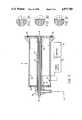
- FIG. 1illustrates a typical embodiment of the invention wherein the aerosol generator 5 has a single tube cylindrical capillary configuration comprising a single tube metal capillary restrictor 10 through which supercritical fluid or gas flows from supply 30 into the decompression chamber 40.
- a typical restrictor 10, as shownis a twenty-five micrometer i.d. stainless steel tube.
- the tip of the capillary restrictor 10is either a capillary nozzle as shown in FIG. 1A, a converging nozzle as shown in FIG. 1B, or a supersonic nozzle as shown in FIG. 1C. Aerosol is generated by rapid decompression of high density solute laden supercritical fluid or gases into the decompression chamber 40.
- Thermodynamic processes at the tip of the aerosol generatorare controlled by either adding or removing heat from the flowing supercritical fluid or gas stream.
- the metal capillary restrictor 10is heated resistively by means of power supply 20. Electrical connections are made at points 21 and 22.
- electrical connections 21 and 22are isolated by a ring insulator 13.
- the temperature of the aerosol generatoris controlled by a feedback sensor 24 to a heater controller 23, feedback sensor 24 being a thermocouple. Other appropriate temperature feedback and control apparatus may also be used as will occur to one skilled in the art.
- Aerosol generator 5is encased for safety by outer casing 28 and attached to the decompression chamber 40 at seal 29, said seal being a vacuum seal such as an 0-ring seal or other appropriate vacuum connection.
- FIG. 2illustrates a typical embodiment of the invention wherein aerosol generator 5 comprises a dual-tube cylindrical capillary configuration; comprising an inner capillary 10 through which the supercritical fluid or gas flows from supply 30 into the decompression chamber 40, and an outer capillary 12 confining the interstitial flow of sheath gas from supply 31 into decompression chamber 40.
- the function of the sheath gasis to conduct heat across the interstitial space between the inner and outer capillary tubes 10 and 12. Consequently, it functions as a means for heating or cooling supercritical fluid or gas flow stream which transmits through inner capillary 10.
- the sheath gasis preferred to be, but not limited to, a high thermal conductive material such as helium or hydrogen.
- the sheath gasserves to form a shield that surrounds the aerosol as it expands into decompression chamber 40.
- Flow of the sheath gasis controlled by sheath gas flow control 32.
- Flow tubes from supercritical fluid or gas supply 30 and sheath gas supply 31intersect in a tee union 16 where the flow emerges therefrom in an orientation which is a function of the relative positioning of the capillary restrictors 10 and 12.
- Capillary restrictor 10may have a restrictor tip that is of capillary geometry as shown in FIG. 2A, converging geometry as shown in FIG. 2B, or supersonic geometry as shown in FIG. 2C.
- Capillary tube 12may also have restrictor tips of the configurations shown in FIGS. 2A, 2B and 2C.
- This particular embodiment of the aerosol generator section of the present deviceutilizes resistive heating of outer capillary 12, such outer capillary being, but not limited to, a conductive material such as nickel or stainless steel.
- the location of the end of the tube 10 relative to the end of tube 12may be varied by adjusting their relative lateral dispositions by minor amounts, within limits, to produce different dispersion of the emerging aerosol in a manner comparable to well-known hose nozzles.
- Power supply 20supplies sufficient wattage to heat outer capillary 12, the highest resistance component in the electrical circuit, with electrical connections at points 21 and 22 and electrical isolation by ring insulator 13, as before.
- the aerosol generatoris encased for safety by outer casing 28 and attached to the decompression chamber 40 at seal 29, said seal being a vacuum seal such as an 0-ring seal or other appropriate vacuum connection.
- FIG. 3illustrates a typical embodiment of the invention wherein aerosol generator 5 comprises a dual-tube cylindrical capillary configuration; comprising a inner capillary 10, through which the supercritical fluid or gas flows from supply 30 into decompression chamber 40, and an outer capillary 12 confining between tubes 11 and 12 the interstitial flow of sheath liquid from supply 33.
- the sheath liquidfunctions to provide back pressure to the flow of supercritical fluid or gas at the exit of inner capillary 10 or to provide surface for condensation of expanding solutes originating from the supercritical fluid or gas stream.
- the lateral distance between the tips for capillary tubes 10 and 12can be adjusted to produce different aerosol characteristics.
- the flow tubes from supercritical fluid or gas supply 30 and sheath liquid supply 33intersect at tee union 16 where the flow emerges therefrom in an orientation which is a function of the relative positioning of capillary tubes 10 and 12.
- This particular embodiment of the aerosol generator section of the present deviceutilizes resistive heating of the outer capillary 12, such outer capillary being, but not limited to, a conductive material such as nickel or stainless steel. Resistive heating of outer tube 12 is the source of heat for the liquid stream. Under some heating conditions the liquid is thermally nebulized to generate small liquid droplets or solute particles from dissolved components in the liquid stream.
- Capillary tubes 10 and 12may have restrictor tips that are of capillary geometric, converging geometry, or supersonic nozzle geometry as shown respectively in FIGS. 3A, 3B and 3C, for capillary tube 10, respectively.
- Power supply 20supplies sufficient electrical power to heat outer capillary 12, the highest resistance component in the electrical circuit, with electrical connections at points 21 and 22 and electrical isolation by ring insulator 13.
- the aerosol generatoris encased for safety by outer casing 28 and attached to the decompression chamber 40 at seal 29, such seal being a vacuum seal, e.g. an O-ring seal or other appropriate vacuum connection.
- FIG. 4illustrates a further typical embodiment of the invention wherein the aerosol generator 5 comprises a triple-tube cylindrical capillary configuration; comprising an inner capillary 10 through which supercritical fluid or gas flows into decompression chamber 40, an outer capillary 12 confining the interstitial flow of sheath gas from sheath gas supply 31, and an intermediate diameter capillary 11 confining the interstitial flow of sheath liquid from liquid supply 33.
- the sheath liquidfunctions to provide back pressure to the flow of supercritical fluid or gas at the exit of inner capillary 10 or provide surface for condensation of expanding solutes originating from the supercricital fluid or gas stream.
- the flow tubes from supercritical fluid or gas supply 30 and sheath liquid supply 33intersect at a tee union 17 where the flow emerges therefrom in an orientation which is a function of the relative positioning of capillary tubes 10, 11 and 12.
- the sheath gas functionis to conduct heat across the interstitial space between intermediate tube 11 and tube 12. Consequently it functions as a means of heating liquid flowing in the interstitial space between capillaries 10 and 11.
- the sheath gasis preferred to be, but not limited to, a high thermal conductive material such as helium or hydrogen.
- the sheath gasserves to sheath the aerosol as it expands into the decompression chamber 40.
- the flow of the sheath gasis controlled by sheath gas flow control 32.
- the concentric flow of supercritical fluid or gas from tee 17intersects the flow of sheath gas from sheath gas supply 31 at tee union 16 where the flow emerges therefrom in an orientation which is a function of the relative position of capillary tubes 10, 11, and 12.
- This particular embodiment of the aerosol generator section of the present deviceutilizes resistive heating of the outer capillary 12, such outer capillary being, but not limited to, a conductive material such as nickel or stainless steel. Resistive heating of outer tube 12 is the source of heat to the liquid stream. Under some heating conditions the liquid is thermally nebulized to generate small liquid droplets or solute particles from dissolved components in the liquid stream. Any or all of the three capillary tubes 10, 11, and 12 may have restrictor tips that are of capillary geometry, converging geometry, or supersonic nozzle geometry as shown in FIGS. 4A, 4B and 4C, for capillary tube 10, respectively.
- Power supply 20supplies electrical power sufficient to heat the outer capillary tube 12, the highest resistance component in the electrical circuit, with electrical connections at points 21 and 22 and electrical isolation by ring insulator 13.
- the aerosol generatoris encased for safety by outer casing 28 and attached to the decompression chamber 40 at seal 29, such seal being a vacuum seal such as an 0-ring seal or other appropriate vacuum connection.
- FIG. 5illustrates an embodiment of the present invention with single-stage particle beam enrichment.
- the deviceis composed of three components parts, namely, aerosol generator 5, a single-stage particle beam or momentum separator 7, and an ion source 60 for a typical mass spectrometer 61.
- Aerosol generator 5is attached to decompression chamber 40 at sealed joint 29.
- the combination of aerosol generator and decompression chamberis attached to ion source chamber 60 via flange joint 62.
- Aerosol generator 5 illustrated in this figureis the dual capillary type as described with reference to FIG. 2. However, the interfacing of generator 5 with the compression chamber 40 is such that any aerosol generator as described with reference to FIGS.
- Aerosol generated by aerosol generator 5expands axially in decompression chamber 40 and is carried in viscous flow downstream toward nozzle 42.
- the solute particles and vapor components of the aerosolare accelerated through nozzle 42, forming a high velocity aerosol beam along a longitudinal axis between nozzle 42 and skimmer 43.
- the aerosol beamis formed due to the pressure drop between decompression chamber 40 and vacuum chamber 41 which surround nozzle 42.
- Vacuum chamber 41is evacuated by pump 44, generally a large pumping capacity mechanical vacuum pump such as a 400 L/min rotary pump.
- the gas and vapor constituents of the aerosolexpand significantly more rapidly than the solute particles.
- the particlesare highly enriched at the axis of the expanding aerosol beam.
- the enriched solute particlesare sampled into the ion source chamber 60 of the mass spectrometer through skimmer 43.
- An enriched solute particle beamis formed from the skimmer to the ionization region 61 of the mass spectrometer.
- FIG. 6illustrates an embodiment of the present invention with dual-stage particle beam enrichment.
- the deviceis composed of three component parts; namely, aerosol generator 5, dual-stage particle, beam or momentum separator 7, and the ion source chamber 60 of a typical mass spectrometer.
- the deviceis attached to ion source chamber 60 of the mass spectrometer via flange joint 62.
- Aerosol generator 5is attached to the decompression chamber 40 at sealed joint 29.
- the aerosol generator 5, illustrated in this figureis the dual capillary type as described with reference to FIG. 2, however, this interfacing device is adapted to operate with any aerosol generator 5 described with reference to FIGS. 1-4 or other aerosol generators whereby solute particles are generated at the end of the supercritical fluid or gas stream.
- the aerosol generated by aerosol generator 5expands axially in decompression chamber 40 and is carried in viscous flow downstream toward nozzle 42. Solute particles and vapor components of the aerosol are accelerated through nozzle 42, forming a high velocity aerosol beam along a longitudinal axis between nozzle 42 and skimmer 43.
- the aerosol beamforms due to the pressure drop between decompression chamber 40 and vacuum chamber 41.
- the first vacuum chamber 41is evacuated by vacuum pump 44, generally a large pumping capacity mechanical pump such as a 400 L/min rotary pump. In the region between axially aligned nozzle 42 and skimmer 43, the gas and vapor constituents of the aerosol expand more rapidly than the solute particles.
- a second vacuum chamber 46evacuated by pump 45, provides a higher degree of solute enrichment by pumping away additional aerosol vapor in the region between skimmer 43 and skimmer 49.
- the enriched solute particlesare sampled into the ion source of the mass spectrometer through skimmer 49.
- An enriched solute particle beamis formed from the skimmer to the ionization region 61 of the mass spectrometer.
- the deviceis connected to a supercritical fluid chromatograph or a liquid chromatograph and to a fluid source or sources as desired. Then, depending on the specific device involved, one, two or three fluid flows are used which are caused to flow through one, two or three tubes at the desired pressures, temperatures, and nozzle adjustments depending on the particular applications. The arrangements of the tube or tubes used and the characteristics of the fluids are selected and adjusted to produce specific aerosols having the desired properties.
- the aerosolsslow to a ,viscous flow in the decompression chamber 40 and then are accelerated through the system by reason of the pressure drops, as previously described, into the ion source of the mass spectrometer (or into an alternate detector) where the aerosols are vaporized and ionized for subsequent mass analysis.
- CIion molecule reactions
- EIelectron impaction ionization
- Analysis of the ionized materialis then carried out by the mass spectrometer by conventional mass spectrometry.
Landscapes
- Chemical & Material Sciences (AREA)
- Analytical Chemistry (AREA)
- Dispersion Chemistry (AREA)
- Other Investigation Or Analysis Of Materials By Electrical Means (AREA)
Abstract
Description
Claims (12)
Priority Applications (1)
| Application Number | Priority Date | Filing Date | Title |
|---|---|---|---|
| US07/157,626US4977785A (en) | 1988-02-19 | 1988-02-19 | Method and apparatus for introduction of fluid streams into mass spectrometers and other gas phase detectors |
Applications Claiming Priority (1)
| Application Number | Priority Date | Filing Date | Title |
|---|---|---|---|
| US07/157,626US4977785A (en) | 1988-02-19 | 1988-02-19 | Method and apparatus for introduction of fluid streams into mass spectrometers and other gas phase detectors |
Publications (1)
| Publication Number | Publication Date |
|---|---|
| US4977785Atrue US4977785A (en) | 1990-12-18 |
Family
ID=22564560
Family Applications (1)
| Application Number | Title | Priority Date | Filing Date |
|---|---|---|---|
| US07/157,626Expired - Fee RelatedUS4977785A (en) | 1988-02-19 | 1988-02-19 | Method and apparatus for introduction of fluid streams into mass spectrometers and other gas phase detectors |
Country Status (1)
| Country | Link |
|---|---|
| US (1) | US4977785A (en) |
Cited By (62)
| Publication number | Priority date | Publication date | Assignee | Title |
|---|---|---|---|---|
| US5055677A (en)* | 1989-07-13 | 1991-10-08 | Aviv Amirav | Mass spectrometer method and apparatus for analyzing materials |
| US5122670A (en)* | 1991-05-17 | 1992-06-16 | Finnigan Corporation | Multilayer flow electrospray ion source using improved sheath liquid |
| US5162651A (en)* | 1990-10-26 | 1992-11-10 | Hitachi, Ltd. | Mass spectrometer |
| US5170053A (en)* | 1990-08-30 | 1992-12-08 | Finnigan Corporation | Electrospray ion source and interface apparatus and method |
| US5170052A (en)* | 1990-04-18 | 1992-12-08 | Hitachi, Ltd. | Apparatus for sample ionization and mass spectrometry |
| US5192865A (en)* | 1992-01-14 | 1993-03-09 | Cetac Technologies Inc. | Atmospheric pressure afterglow ionization system and method of use, for mass spectrometer sample analysis systems |
| US5196700A (en)* | 1990-11-30 | 1993-03-23 | Shimadzu Corporation | Ion source of mass spectrometer |
| US5259254A (en)* | 1991-09-25 | 1993-11-09 | Cetac Technologies, Inc. | Sample introduction system for inductively coupled plasma and other gas-phase, or particle, detectors utilizing ultrasonic nebulization, and method of use |
| US5266192A (en)* | 1991-09-12 | 1993-11-30 | General Electric Company | Apparatus for interfacing liquid chromatograph with magnetic sector spectrometer |
| USRE34757E (en)* | 1988-04-05 | 1994-10-18 | Battelle Memorial Institute | Combined electrophoresis-electrospray interface and method |
| US5406079A (en)* | 1992-10-20 | 1995-04-11 | Hitachi, Ltd. | Ionization device for ionizing liquid sample |
| US5428220A (en)* | 1993-11-29 | 1995-06-27 | The United States Of America As Represented By The Secretary Of Commerce | Aerosol mass spectrometer and method of classifying aerosol particles according to specific mass |
| US5526682A (en)* | 1991-05-02 | 1996-06-18 | Waters Investments Limited | Method and apparatus for analyzing sample solutions |
| US5561066A (en)* | 1995-04-20 | 1996-10-01 | The United States Of America As Represented By The Administrator Of The National Aeronautics And Space Administration | Analysis of supercritical-extracted chelated metal ions from mixed organic-inorganic samples |
| WO1997028556A1 (en)* | 1996-01-31 | 1997-08-07 | Hewlett-Packard Company | Apparatus for forming liquid droplets having a mechanically fixed inner microtube |
| US5750988A (en)* | 1994-07-11 | 1998-05-12 | Hewlett-Packard Company | Orthogonal ion sampling for APCI mass spectrometry |
| WO1998023952A1 (en)* | 1996-11-26 | 1998-06-04 | Anglo American Research Laboratories (Proprietary) Limited | Nebulizer |
| US5828062A (en)* | 1997-03-03 | 1998-10-27 | Waters Investments Limited | Ionization electrospray apparatus for mass spectrometry |
| US5898175A (en)* | 1995-09-07 | 1999-04-27 | Hitachi, Ltd. | Mass spectrometer and mass spectrometry method for analyzing compounds contained in a solution |
| EP1004878A1 (en)* | 1998-11-23 | 2000-05-31 | Aviv Amirav | Mass spectrometer method and apparatus for analyzing a sample in a solution |
| USRE36892E (en)* | 1994-07-11 | 2000-10-03 | Agilent Technologies | Orthogonal ion sampling for electrospray .[.LC/MS.]. mass spectrometry |
| US6147347A (en)* | 1994-03-15 | 2000-11-14 | Hitachi, Ltd. | Ion source and mass spectrometer instrument using the same |
| US6197835B1 (en)* | 1996-05-13 | 2001-03-06 | Universidad De Sevilla | Device and method for creating spherical particles of uniform size |
| US6278111B1 (en) | 1995-08-21 | 2001-08-21 | Waters Investments Limited | Electrospray for chemical analysis |
| US6446883B1 (en)* | 1999-09-06 | 2002-09-10 | Hitachi, Ltd. | Nebulizer |
| US20030003595A1 (en)* | 1998-11-23 | 2003-01-02 | Aviv Amirav | Mass spectrometer method and apparatus for analyzing a sample in a solution |
| US6515290B1 (en)* | 2000-09-05 | 2003-02-04 | Axcelis Technologies, Inc. | Bulk gas delivery system for ion implanters |
| US20030109421A1 (en)* | 2001-07-20 | 2003-06-12 | Srinivas Palakodaty | Particle formation |
| US6583407B1 (en)* | 1999-10-29 | 2003-06-24 | Agilent Technologies, Inc. | Method and apparatus for selective ion delivery using ion polarity independent control |
| US20030209201A1 (en)* | 2002-05-13 | 2003-11-13 | Japan Pionics Co., Ltd. | Vaporizer and apparatus for vaporizing and supplying |
| US6690006B2 (en) | 2001-05-24 | 2004-02-10 | New Objective, Inc. | Method and apparatus for multiple electrospray sample introduction |
| US20040149902A1 (en)* | 2001-06-15 | 2004-08-05 | Park Melvin A. | Means and method for guiding ions in a mass spectrometer |
| WO2003104765A3 (en)* | 2002-06-10 | 2004-08-19 | Tufts College | Total organic carbon (toc) analyzer |
| US6809314B2 (en)* | 1998-11-05 | 2004-10-26 | Matsushita Electric Industrial Co., Ltd. | Fine particle classification apparatus and method for classifying aerosol particles in a sheath gas |
| US6840456B1 (en)* | 2002-09-11 | 2005-01-11 | The United States Of America As Represented By The Secretary Of The Army | Injection valves |
| US20050006291A1 (en)* | 2003-07-08 | 2005-01-13 | Shimadzu Corporation | Fractionating apparatus for liquid chromatography |
| US6848633B2 (en)* | 2001-04-27 | 2005-02-01 | Tecan Trading Ag | Spray device |
| US6860907B1 (en) | 1999-07-07 | 2005-03-01 | Nektar Therapeutica | Method of particle formation |
| US20050147536A1 (en)* | 2004-01-06 | 2005-07-07 | Shimadzu Corporation | Fractionating apparatus |
| US20050158215A1 (en)* | 2004-01-19 | 2005-07-21 | Shimadzu Corporation | Fractionating apparatus |
| GB2410831A (en)* | 2004-02-06 | 2005-08-10 | Micromass Ltd | Ion source for a mass spectrometer |
| US20050230634A1 (en)* | 2004-02-06 | 2005-10-20 | Micromass Uk Limited | Mass spectrometer |
| US20050269518A1 (en)* | 2004-02-06 | 2005-12-08 | Micromass Uk Limited | Mass spectrometer |
| US20060073087A1 (en)* | 1994-06-30 | 2006-04-06 | Hanna Mazen H | Method and apparatus for the formation of particles |
| US20080048664A1 (en)* | 2004-08-20 | 2008-02-28 | Shimadzu Corporation | Specimen Pretreating Device and Probe Used Therefor |
| US20080210086A1 (en)* | 2003-08-22 | 2008-09-04 | Masayuki Toda | Dispenser For Carburetor, Carburetor For Mocvd Using the Dispenser For Carburetor, and Carrier Gas Vaporizing Method |
| US20080268060A1 (en)* | 2003-06-13 | 2008-10-30 | Philip Morris Usa Inc. | Methods and apparatus for producing nanoscale particles |
| US20080279614A1 (en)* | 2004-11-04 | 2008-11-13 | Tom Juul Andersen | Device and a Method For Dosage of Fluids |
| US20090230215A1 (en)* | 2008-03-11 | 2009-09-17 | Microjet Gmbh | Apparatus for generating and spraying an aerosol |
| US20100267160A1 (en)* | 2006-02-09 | 2010-10-21 | OI Analytical | Total Organic Carbon Analysis |
| US7967221B2 (en) | 2002-12-30 | 2011-06-28 | Novartis Ag | Prefilming atomizer |
| DE102010034732A1 (en)* | 2010-08-18 | 2012-02-23 | Karlsruher Institut für Technologie | Device, useful for determining the fragmentation energy of nanoparticle agglomerates, comprises an evacuable vacuum housing having two chambers, first pump with which pressure is adjusted in the first chamber, and second pump |
| US8517722B1 (en)* | 2010-05-12 | 2013-08-27 | Elemental Scientific, Inc. | Torch assembly |
| CN103900892A (en)* | 2014-03-25 | 2014-07-02 | 北京元盛科仪科技有限责任公司 | Aerosol diluting device |
| JP2016533010A (en)* | 2013-08-07 | 2016-10-20 | ディーエイチ テクノロジーズ デベロップメント プライベート リミテッド | Increased spray formation for liquid samples |
| EP2986704A4 (en)* | 2013-04-19 | 2016-12-07 | Siemens Healthcare Diagnostics Inc | CONTACTLESS MICRO-DROPLECTOR DISPENSER AND CORRESPONDING METHOD |
| US20170274380A1 (en)* | 2014-09-08 | 2017-09-28 | Uwe Weierstall | Nozzle apparatus and methods for use thereof |
| US9929000B2 (en)* | 2013-10-25 | 2018-03-27 | Waters Technologies Corporation | Method and an apparatus for ionizing a sample |
| US20190056300A1 (en)* | 2015-11-13 | 2019-02-21 | Virginia Commonwealth University | Curved classifiers and classification methods |
| CN109839421A (en)* | 2017-11-27 | 2019-06-04 | 中国科学院大连化学物理研究所 | The method quickly detected for the direct mass spectrography of semi-volatile organic matter in liquid |
| JP2021067311A (en)* | 2019-10-23 | 2021-04-30 | 株式会社三井E&Sマシナリー | Electrical insulation device for gas supply, and plasma processing device |
| CN113954364A (en)* | 2021-09-22 | 2022-01-21 | 西安交通大学 | A micro or nano aerosol particle enrichment device |
Citations (14)
| Publication number | Priority date | Publication date | Assignee | Title |
|---|---|---|---|---|
| US3944826A (en)* | 1973-07-19 | 1976-03-16 | Applied Research Laboratories Limited | Methods and apparatus for analyzing mixtures |
| US3997298A (en)* | 1975-02-27 | 1976-12-14 | Cornell Research Foundation, Inc. | Liquid chromatography-mass spectrometry system and method |
| US4160161A (en)* | 1978-05-30 | 1979-07-03 | Phillips Petroleum Company | Liquid chromatograph/mass spectrometer interface |
| US4298795A (en)* | 1978-09-08 | 1981-11-03 | Japan Spectroscopic Co. Ltd | Method and apparatus for introducing samples to a mass spectrometer |
| US4358302A (en)* | 1980-11-24 | 1982-11-09 | The University Of Rochester | Apparatus for separation of gas borne particles |
| US4383171A (en)* | 1980-11-17 | 1983-05-10 | The United States Of America As Represented By The Administrator Of The National Aeronautics And Space Administration | Particle analyzing method and apparatus |
| US4531056A (en)* | 1983-04-20 | 1985-07-23 | Yale University | Method and apparatus for the mass spectrometric analysis of solutions |
| US4607163A (en)* | 1983-12-19 | 1986-08-19 | Jeol Ltd. | Device for coupling a liquid chromatograph and a mass spectrometer |
| US4629478A (en)* | 1984-06-22 | 1986-12-16 | Georgia Tech Research Corporation | Monodisperse aerosol generator |
| US4687929A (en)* | 1984-06-22 | 1987-08-18 | Georgia Tech Research Corporation | Monodisperse aerosol generator |
| US4762995A (en)* | 1984-06-22 | 1988-08-09 | Georgia Tech Research Corporation | Monodisperse aerosol generator |
| US4861988A (en)* | 1987-09-30 | 1989-08-29 | Cornell Research Foundation, Inc. | Ion spray apparatus and method |
| US4891515A (en)* | 1987-01-30 | 1990-01-02 | Vg Instruments Group Limited | Solution analyzing mass spectrometer |
| US4916077A (en)* | 1987-02-27 | 1990-04-10 | Shell Oil Company | Method and apparatus for oxidative decomposition and analysis of a sample |
- 1988
- 1988-02-19USUS07/157,626patent/US4977785A/ennot_activeExpired - Fee Related
Patent Citations (14)
| Publication number | Priority date | Publication date | Assignee | Title |
|---|---|---|---|---|
| US3944826A (en)* | 1973-07-19 | 1976-03-16 | Applied Research Laboratories Limited | Methods and apparatus for analyzing mixtures |
| US3997298A (en)* | 1975-02-27 | 1976-12-14 | Cornell Research Foundation, Inc. | Liquid chromatography-mass spectrometry system and method |
| US4160161A (en)* | 1978-05-30 | 1979-07-03 | Phillips Petroleum Company | Liquid chromatograph/mass spectrometer interface |
| US4298795A (en)* | 1978-09-08 | 1981-11-03 | Japan Spectroscopic Co. Ltd | Method and apparatus for introducing samples to a mass spectrometer |
| US4383171A (en)* | 1980-11-17 | 1983-05-10 | The United States Of America As Represented By The Administrator Of The National Aeronautics And Space Administration | Particle analyzing method and apparatus |
| US4358302A (en)* | 1980-11-24 | 1982-11-09 | The University Of Rochester | Apparatus for separation of gas borne particles |
| US4531056A (en)* | 1983-04-20 | 1985-07-23 | Yale University | Method and apparatus for the mass spectrometric analysis of solutions |
| US4607163A (en)* | 1983-12-19 | 1986-08-19 | Jeol Ltd. | Device for coupling a liquid chromatograph and a mass spectrometer |
| US4629478A (en)* | 1984-06-22 | 1986-12-16 | Georgia Tech Research Corporation | Monodisperse aerosol generator |
| US4687929A (en)* | 1984-06-22 | 1987-08-18 | Georgia Tech Research Corporation | Monodisperse aerosol generator |
| US4762995A (en)* | 1984-06-22 | 1988-08-09 | Georgia Tech Research Corporation | Monodisperse aerosol generator |
| US4891515A (en)* | 1987-01-30 | 1990-01-02 | Vg Instruments Group Limited | Solution analyzing mass spectrometer |
| US4916077A (en)* | 1987-02-27 | 1990-04-10 | Shell Oil Company | Method and apparatus for oxidative decomposition and analysis of a sample |
| US4861988A (en)* | 1987-09-30 | 1989-08-29 | Cornell Research Foundation, Inc. | Ion spray apparatus and method |
Cited By (101)
| Publication number | Priority date | Publication date | Assignee | Title |
|---|---|---|---|---|
| USRE34757E (en)* | 1988-04-05 | 1994-10-18 | Battelle Memorial Institute | Combined electrophoresis-electrospray interface and method |
| US5055677A (en)* | 1989-07-13 | 1991-10-08 | Aviv Amirav | Mass spectrometer method and apparatus for analyzing materials |
| US5170052A (en)* | 1990-04-18 | 1992-12-08 | Hitachi, Ltd. | Apparatus for sample ionization and mass spectrometry |
| US5170053A (en)* | 1990-08-30 | 1992-12-08 | Finnigan Corporation | Electrospray ion source and interface apparatus and method |
| US5393975A (en)* | 1990-08-30 | 1995-02-28 | Finnigan Corporation | Electrospray ion source and interface apparatus and method |
| US5162651A (en)* | 1990-10-26 | 1992-11-10 | Hitachi, Ltd. | Mass spectrometer |
| US5196700A (en)* | 1990-11-30 | 1993-03-23 | Shimadzu Corporation | Ion source of mass spectrometer |
| US5526682A (en)* | 1991-05-02 | 1996-06-18 | Waters Investments Limited | Method and apparatus for analyzing sample solutions |
| GB2256524B (en)* | 1991-05-17 | 1995-04-05 | Finnigan Corp | Multilayer flow electrospray ion source using improved sheath liquid |
| GB2256524A (en)* | 1991-05-17 | 1992-12-09 | Finnigan Corp | Multilayer flow electrospray ion source using improved sheath liquid. |
| US5122670A (en)* | 1991-05-17 | 1992-06-16 | Finnigan Corporation | Multilayer flow electrospray ion source using improved sheath liquid |
| US5266192A (en)* | 1991-09-12 | 1993-11-30 | General Electric Company | Apparatus for interfacing liquid chromatograph with magnetic sector spectrometer |
| US5259254A (en)* | 1991-09-25 | 1993-11-09 | Cetac Technologies, Inc. | Sample introduction system for inductively coupled plasma and other gas-phase, or particle, detectors utilizing ultrasonic nebulization, and method of use |
| US5192865A (en)* | 1992-01-14 | 1993-03-09 | Cetac Technologies Inc. | Atmospheric pressure afterglow ionization system and method of use, for mass spectrometer sample analysis systems |
| US5406079A (en)* | 1992-10-20 | 1995-04-11 | Hitachi, Ltd. | Ionization device for ionizing liquid sample |
| US5428220A (en)* | 1993-11-29 | 1995-06-27 | The United States Of America As Represented By The Secretary Of Commerce | Aerosol mass spectrometer and method of classifying aerosol particles according to specific mass |
| US7645983B2 (en)* | 1994-03-15 | 2010-01-12 | Hitachi, Ltd. | Ion source and mass spectrometer instrument using the same |
| US20080237459A1 (en)* | 1994-03-15 | 2008-10-02 | Atsumu Hirabayashi | Ion source and mass spectrometer instrument using the same |
| US20020125426A1 (en)* | 1994-03-15 | 2002-09-12 | Atsumu Hirabayashi | Ion source and mass spectrometer instrument using the same |
| US6384411B1 (en) | 1994-03-15 | 2002-05-07 | Hitachi, Ltd. | Ion source and mass spectrometer instrument using the same |
| US6147347A (en)* | 1994-03-15 | 2000-11-14 | Hitachi, Ltd. | Ion source and mass spectrometer instrument using the same |
| US20060073087A1 (en)* | 1994-06-30 | 2006-04-06 | Hanna Mazen H | Method and apparatus for the formation of particles |
| USRE36892E (en)* | 1994-07-11 | 2000-10-03 | Agilent Technologies | Orthogonal ion sampling for electrospray .[.LC/MS.]. mass spectrometry |
| US5750988A (en)* | 1994-07-11 | 1998-05-12 | Hewlett-Packard Company | Orthogonal ion sampling for APCI mass spectrometry |
| US5561066A (en)* | 1995-04-20 | 1996-10-01 | The United States Of America As Represented By The Administrator Of The National Aeronautics And Space Administration | Analysis of supercritical-extracted chelated metal ions from mixed organic-inorganic samples |
| US6278111B1 (en) | 1995-08-21 | 2001-08-21 | Waters Investments Limited | Electrospray for chemical analysis |
| US5898175A (en)* | 1995-09-07 | 1999-04-27 | Hitachi, Ltd. | Mass spectrometer and mass spectrometry method for analyzing compounds contained in a solution |
| US6114693A (en)* | 1995-09-07 | 2000-09-05 | Hitachi, Ltd. | Mass spectrometer and mass spectrometry method for analyzing compounds contained in a solution |
| US5868322A (en)* | 1996-01-31 | 1999-02-09 | Hewlett-Packard Company | Apparatus for forming liquid droplets having a mechanically fixed inner microtube |
| WO1997028556A1 (en)* | 1996-01-31 | 1997-08-07 | Hewlett-Packard Company | Apparatus for forming liquid droplets having a mechanically fixed inner microtube |
| US6197835B1 (en)* | 1996-05-13 | 2001-03-06 | Universidad De Sevilla | Device and method for creating spherical particles of uniform size |
| US6464886B2 (en) | 1996-05-13 | 2002-10-15 | Universidad De Sevilla | Device and method for creating spherical particles of uniform size |
| WO1998023952A1 (en)* | 1996-11-26 | 1998-06-04 | Anglo American Research Laboratories (Proprietary) Limited | Nebulizer |
| US5828062A (en)* | 1997-03-03 | 1998-10-27 | Waters Investments Limited | Ionization electrospray apparatus for mass spectrometry |
| US6809314B2 (en)* | 1998-11-05 | 2004-10-26 | Matsushita Electric Industrial Co., Ltd. | Fine particle classification apparatus and method for classifying aerosol particles in a sheath gas |
| US20030003595A1 (en)* | 1998-11-23 | 2003-01-02 | Aviv Amirav | Mass spectrometer method and apparatus for analyzing a sample in a solution |
| US7247495B2 (en)* | 1998-11-23 | 2007-07-24 | Aviv Amirav | Mass spectrometer method and apparatus for analyzing a sample in a solution |
| EP1004878A1 (en)* | 1998-11-23 | 2000-05-31 | Aviv Amirav | Mass spectrometer method and apparatus for analyzing a sample in a solution |
| US6860907B1 (en) | 1999-07-07 | 2005-03-01 | Nektar Therapeutica | Method of particle formation |
| US20050206023A1 (en)* | 1999-07-07 | 2005-09-22 | Hanna Mazen H | Method of particle formation |
| US7150766B2 (en) | 1999-07-07 | 2006-12-19 | Nektar Therapeutics Uk, Ltd. | Method of particle formation |
| US6499675B2 (en) | 1999-09-06 | 2002-12-31 | Hitachi, Ltd. | Analytical apparatus using nebulizer |
| US6446883B1 (en)* | 1999-09-06 | 2002-09-10 | Hitachi, Ltd. | Nebulizer |
| US6583407B1 (en)* | 1999-10-29 | 2003-06-24 | Agilent Technologies, Inc. | Method and apparatus for selective ion delivery using ion polarity independent control |
| US6515290B1 (en)* | 2000-09-05 | 2003-02-04 | Axcelis Technologies, Inc. | Bulk gas delivery system for ion implanters |
| US6848633B2 (en)* | 2001-04-27 | 2005-02-01 | Tecan Trading Ag | Spray device |
| WO2002095360A3 (en)* | 2001-05-24 | 2007-11-15 | New Objective Inc | Method and apparatus for multiple electrospray sample introduction |
| US6690006B2 (en) | 2001-05-24 | 2004-02-10 | New Objective, Inc. | Method and apparatus for multiple electrospray sample introduction |
| US6956205B2 (en) | 2001-06-15 | 2005-10-18 | Bruker Daltonics, Inc. | Means and method for guiding ions in a mass spectrometer |
| US20040149902A1 (en)* | 2001-06-15 | 2004-08-05 | Park Melvin A. | Means and method for guiding ions in a mass spectrometer |
| US20030109421A1 (en)* | 2001-07-20 | 2003-06-12 | Srinivas Palakodaty | Particle formation |
| US20060279011A1 (en)* | 2001-07-20 | 2006-12-14 | Srinivas Palakodaty | Particle formation |
| US7087197B2 (en) | 2001-07-20 | 2006-08-08 | Nektar Therapeutics | Particle formation |
| US20060280823A1 (en)* | 2001-07-20 | 2006-12-14 | Srinivas Palakodaty | Particle formation |
| US20030209201A1 (en)* | 2002-05-13 | 2003-11-13 | Japan Pionics Co., Ltd. | Vaporizer and apparatus for vaporizing and supplying |
| US7036801B2 (en)* | 2002-05-13 | 2006-05-02 | Japan Pionics Co., Ltd. | Vaporizer and apparatus for vaporizing and supplying |
| US20060125129A1 (en)* | 2002-05-13 | 2006-06-15 | Japan Pionics Co., Ltd. | Vaporizer and apparatus for vaporizing and supplying |
| US20100089773A1 (en)* | 2002-06-10 | 2010-04-15 | Trustees Of Tufts College | Total organic compound (toc) analyzer |
| WO2003104765A3 (en)* | 2002-06-10 | 2004-08-19 | Tufts College | Total organic carbon (toc) analyzer |
| US8216447B2 (en) | 2002-06-10 | 2012-07-10 | O.I. Corporation | Total organic compound (TOC) analyzer |
| US6840456B1 (en)* | 2002-09-11 | 2005-01-11 | The United States Of America As Represented By The Secretary Of The Army | Injection valves |
| US7967221B2 (en) | 2002-12-30 | 2011-06-28 | Novartis Ag | Prefilming atomizer |
| US8616464B2 (en) | 2002-12-30 | 2013-12-31 | Novartis Ag | Prefilming atomizer |
| US7625548B2 (en) | 2003-06-13 | 2009-12-01 | Philip Morris Usa Inc. | Methods and apparatus for producing nanoscale particles |
| US20080268060A1 (en)* | 2003-06-13 | 2008-10-30 | Philip Morris Usa Inc. | Methods and apparatus for producing nanoscale particles |
| US7169299B2 (en)* | 2003-07-08 | 2007-01-30 | Shimadzu Corporation | Fractionating apparatus for liquid chromatography |
| US20050006291A1 (en)* | 2003-07-08 | 2005-01-13 | Shimadzu Corporation | Fractionating apparatus for liquid chromatography |
| US20080210086A1 (en)* | 2003-08-22 | 2008-09-04 | Masayuki Toda | Dispenser For Carburetor, Carburetor For Mocvd Using the Dispenser For Carburetor, and Carrier Gas Vaporizing Method |
| US7169300B2 (en)* | 2004-01-06 | 2007-01-30 | Shimadzu Corporation | Fractionating apparatus |
| US20050147536A1 (en)* | 2004-01-06 | 2005-07-07 | Shimadzu Corporation | Fractionating apparatus |
| US7182862B2 (en)* | 2004-01-19 | 2007-02-27 | Shimadzu Corporation | Fractionating apparatus |
| US20050158215A1 (en)* | 2004-01-19 | 2005-07-21 | Shimadzu Corporation | Fractionating apparatus |
| US20050269518A1 (en)* | 2004-02-06 | 2005-12-08 | Micromass Uk Limited | Mass spectrometer |
| US20050230634A1 (en)* | 2004-02-06 | 2005-10-20 | Micromass Uk Limited | Mass spectrometer |
| US7265362B2 (en) | 2004-02-06 | 2007-09-04 | Micromass Uk Limited | Mass spectrometer |
| GB2410831A (en)* | 2004-02-06 | 2005-08-10 | Micromass Ltd | Ion source for a mass spectrometer |
| GB2410831B (en)* | 2004-02-06 | 2008-05-21 | Micromass Ltd | Mass spectrometer |
| US7294841B2 (en) | 2004-02-06 | 2007-11-13 | Micromass Uk Limited | Mass spectrometer |
| US20080048664A1 (en)* | 2004-08-20 | 2008-02-28 | Shimadzu Corporation | Specimen Pretreating Device and Probe Used Therefor |
| US7752896B2 (en)* | 2004-08-30 | 2010-07-13 | Shimadzu Corporation | Specimen pretreating device and probe used therefor |
| US8221016B2 (en)* | 2004-11-04 | 2012-07-17 | Idekontoret Aps | Device and a method for dosage of fluids |
| US20080279614A1 (en)* | 2004-11-04 | 2008-11-13 | Tom Juul Andersen | Device and a Method For Dosage of Fluids |
| US20100267160A1 (en)* | 2006-02-09 | 2010-10-21 | OI Analytical | Total Organic Carbon Analysis |
| US8679408B2 (en) | 2006-02-09 | 2014-03-25 | O.I. Corporation | Total organic carbon analysis |
| US20090230215A1 (en)* | 2008-03-11 | 2009-09-17 | Microjet Gmbh | Apparatus for generating and spraying an aerosol |
| US8517722B1 (en)* | 2010-05-12 | 2013-08-27 | Elemental Scientific, Inc. | Torch assembly |
| DE102010034732A1 (en)* | 2010-08-18 | 2012-02-23 | Karlsruher Institut für Technologie | Device, useful for determining the fragmentation energy of nanoparticle agglomerates, comprises an evacuable vacuum housing having two chambers, first pump with which pressure is adjusted in the first chamber, and second pump |
| US10486152B2 (en) | 2013-04-19 | 2019-11-26 | Siemens Healthcare Diagnostics Inc. | Non-contact micro droplet dispenser and method |
| EP2986704A4 (en)* | 2013-04-19 | 2016-12-07 | Siemens Healthcare Diagnostics Inc | CONTACTLESS MICRO-DROPLECTOR DISPENSER AND CORRESPONDING METHOD |
| JP2016533010A (en)* | 2013-08-07 | 2016-10-20 | ディーエイチ テクノロジーズ デベロップメント プライベート リミテッド | Increased spray formation for liquid samples |
| EP3031068A4 (en)* | 2013-08-07 | 2017-03-22 | DH Technologies Development PTE. Ltd. | Enhanced spray formation for liquid samples |
| US9929000B2 (en)* | 2013-10-25 | 2018-03-27 | Waters Technologies Corporation | Method and an apparatus for ionizing a sample |
| CN103900892A (en)* | 2014-03-25 | 2014-07-02 | 北京元盛科仪科技有限责任公司 | Aerosol diluting device |
| US20170274380A1 (en)* | 2014-09-08 | 2017-09-28 | Uwe Weierstall | Nozzle apparatus and methods for use thereof |
| US10252270B2 (en)* | 2014-09-08 | 2019-04-09 | Arizona Board Of Regents On Behalf Of Arizona State University | Nozzle apparatus and methods for use thereof |
| US20190056300A1 (en)* | 2015-11-13 | 2019-02-21 | Virginia Commonwealth University | Curved classifiers and classification methods |
| US10845288B2 (en)* | 2015-11-13 | 2020-11-24 | Virginia Commonwealth University | Curved classifiers and classification methods |
| CN109839421A (en)* | 2017-11-27 | 2019-06-04 | 中国科学院大连化学物理研究所 | The method quickly detected for the direct mass spectrography of semi-volatile organic matter in liquid |
| JP2021067311A (en)* | 2019-10-23 | 2021-04-30 | 株式会社三井E&Sマシナリー | Electrical insulation device for gas supply, and plasma processing device |
| CN113954364A (en)* | 2021-09-22 | 2022-01-21 | 西安交通大学 | A micro or nano aerosol particle enrichment device |
| CN113954364B (en)* | 2021-09-22 | 2022-10-25 | 西安交通大学 | A micro or nano aerosol particle enrichment device |
Similar Documents
| Publication | Publication Date | Title |
|---|---|---|
| US4977785A (en) | Method and apparatus for introduction of fluid streams into mass spectrometers and other gas phase detectors | |
| US5285064A (en) | Method and apparatus for introduction of liquid effluent into mass spectrometer and other gas-phase or particle detectors | |
| US4968885A (en) | Method and apparatus for introduction of liquid effluent into mass spectrometer and other gas-phase or particle detectors | |
| US7247495B2 (en) | Mass spectrometer method and apparatus for analyzing a sample in a solution | |
| US4982097A (en) | Vaporization device for continuous introduction of liquids into a mass spectrometer | |
| US6236042B1 (en) | Method and apparatus for direct coupling of liquid chromatograph and mass spectrometer, liquid chromatography-mass spectrometry, and liquid chromatograph-mass spectrometer | |
| US4980057A (en) | Apparatus for mass spectrometric analysis of liquid chromatographic fractions | |
| EP0408487B1 (en) | Mass spectrometer method and apparatus for analyzing materials | |
| US5559326A (en) | Self generating ion device for mass spectrometry of liquids | |
| US4935624A (en) | Thermal-assisted electrospray interface (TAESI) for LC/MS | |
| US5015845A (en) | Electrospray method for mass spectrometry | |
| JPS583592B2 (en) | Method and device for introducing sample into mass spectrometer | |
| US7041966B2 (en) | Apparatus for delivering ions from a grounded electrospray assembly to a vacuum chamber | |
| US4861989A (en) | Ion vapor source for mass spectrometry of liquids | |
| JP2827010B2 (en) | Method and apparatus for introducing effluent to mass spectrometers and other gas or particle detectors | |
| EP1004878A1 (en) | Mass spectrometer method and apparatus for analyzing a sample in a solution | |
| CA1162331A (en) | Ion vapor source for mass spectrometry of liquids | |
| EP1315962B1 (en) | Analyte detection system | |
| GB2240176A (en) | Introduction of affluent into mass spectrometers and other gas-phase or particle detectors | |
| Arpino et al. | Design and construction of LC/MS interfaces utilizing fused-silica capillary tubes as vacuum nebulizers | |
| US5526682A (en) | Method and apparatus for analyzing sample solutions | |
| Arpino | Mass spectrometric detectors | |
| EP0512394B1 (en) | Method and apparatus for analyzing sample solutions | |
| JP7677715B2 (en) | Interface between liquid chromatography, ionization device, and mass spectrometer, and sample analysis method using the same | |
| Vestal | [5] Liquid chromatography-mass spectrometry |
Legal Events
| Date | Code | Title | Description |
|---|---|---|---|
| AS | Assignment | Owner name:EXTREL CORPORATION, 240 ALPHA DRIVE, PITTSBURGH, P Free format text:ASSIGNMENT OF ASSIGNORS INTEREST.;ASSIGNORS:WILLOUGHBY, ROSS C.;BUCHNER, JAMES D.;REEL/FRAME:004908/0497 Effective date:19880512 Owner name:EXTREL CORPORATION,PENNSYLVANIA Free format text:ASSIGNMENT OF ASSIGNORS INTEREST;ASSIGNORS:WILLOUGHBY, ROSS C.;BUCHNER, JAMES D.;REEL/FRAME:004908/0497 Effective date:19880512 | |
| AS | Assignment | Owner name:WATERS INVESTMENTS LIMITED, DELAWARE Free format text:ASSIGNMENT OF ASSIGNORS INTEREST;ASSIGNOR:EXTREL CORPORATION;REEL/FRAME:006862/0710 Effective date:19931214 | |
| REMI | Maintenance fee reminder mailed | ||
| AS | Assignment | Owner name:BANKERS TRUST COMPANY, NEW YORK Free format text:SECURITY INTEREST;ASSIGNOR:EXTREL CORPORATION;REEL/FRAME:007145/0445 Effective date:19940818 | |
| LAPS | Lapse for failure to pay maintenance fees | ||
| FP | Lapsed due to failure to pay maintenance fee | Effective date:19951221 | |
| AS | Assignment | Owner name:BANKERS TRUST COMPANY, NEW YORK Free format text:SECURITY INTEREST;ASSIGNOR:WATERS INVESTMENTS LIMITED;REEL/FRAME:007986/0191 Effective date:19951122 | |
| AS | Assignment | Owner name:EXTREL CORPORATION, PENNSYLVANIA Free format text:PATENT RELEASE;ASSIGNOR:BANKERS TRUST COMPANY;REEL/FRAME:008077/0991 Effective date:19951122 | |
| AS | Assignment | Owner name:WATERS INVESTMENTS LIMITED, DELAWARE Free format text:RELEASE OF SECURITY INTEREST IN PATENTS;ASSIGNOR:BANKERS TRUST COMPANY, AS COLLATERAL AGENT;REEL/FRAME:012822/0456 Effective date:20020211 | |
| AS | Assignment | Owner name:WATERS TECHNOLOGIES CORPORATION, MASSACHUSETTS Free format text:MERGER;ASSIGNOR:WATERS INVESTMENTS LIMITED;REEL/FRAME:022552/0606 Effective date:20081117 | |
| STCH | Information on status: patent discontinuation | Free format text:PATENT EXPIRED DUE TO NONPAYMENT OF MAINTENANCE FEES UNDER 37 CFR 1.362 |