US4977647A - Double locking snap hook - Google Patents
Double locking snap hookDownload PDFInfo
- Publication number
- US4977647A US4977647AUS07/427,716US42771689AUS4977647AUS 4977647 AUS4977647 AUS 4977647AUS 42771689 AUS42771689 AUS 42771689AUS 4977647 AUS4977647 AUS 4977647A
- Authority
- US
- United States
- Prior art keywords
- latch member
- shank
- hook
- latch
- locking
- Prior art date
- Legal status (The legal status is an assumption and is not a legal conclusion. Google has not performed a legal analysis and makes no representation as to the accuracy of the status listed.)
- Expired - Lifetime
Links
- 230000000452restraining effectEffects0.000claimsabstract7
- 210000003811fingerAnatomy0.000claimsdescription24
- 241000388002Agonus cataphractusSpecies0.000claimsdescription15
- 210000003813thumbAnatomy0.000claimsdescription15
- 230000004913activationEffects0.000description5
- 238000001994activationMethods0.000description5
- 230000000717retained effectEffects0.000description4
- 230000006978adaptationEffects0.000description1
- 238000004873anchoringMethods0.000description1
- 238000012986modificationMethods0.000description1
- 230000004048modificationEffects0.000description1
- 238000009877renderingMethods0.000description1
Images

Classifications
- F—MECHANICAL ENGINEERING; LIGHTING; HEATING; WEAPONS; BLASTING
- F16—ENGINEERING ELEMENTS AND UNITS; GENERAL MEASURES FOR PRODUCING AND MAINTAINING EFFECTIVE FUNCTIONING OF MACHINES OR INSTALLATIONS; THERMAL INSULATION IN GENERAL
- F16B—DEVICES FOR FASTENING OR SECURING CONSTRUCTIONAL ELEMENTS OR MACHINE PARTS TOGETHER, e.g. NAILS, BOLTS, CIRCLIPS, CLAMPS, CLIPS OR WEDGES; JOINTS OR JOINTING
- F16B45/00—Hooks; Eyes
- F16B45/02—Hooks with pivoting or elastically bending closing member
- F16B45/027—Hooks with pivoting or elastically bending closing member and having position-locking means for the closing member
- F16B45/028—Hooks with pivoting or elastically bending closing member and having position-locking means for the closing member the position-locking means being pivotally connected
- B—PERFORMING OPERATIONS; TRANSPORTING
- B66—HOISTING; LIFTING; HAULING
- B66C—CRANES; LOAD-ENGAGING ELEMENTS OR DEVICES FOR CRANES, CAPSTANS, WINCHES, OR TACKLES
- B66C1/00—Load-engaging elements or devices attached to lifting or lowering gear of cranes or adapted for connection therewith for transmitting lifting forces to articles or groups of articles
- B66C1/10—Load-engaging elements or devices attached to lifting or lowering gear of cranes or adapted for connection therewith for transmitting lifting forces to articles or groups of articles by mechanical means
- B66C1/22—Rigid members, e.g. L-shaped members, with parts engaging the under surface of the loads; Crane hooks
- B66C1/34—Crane hooks
- B66C1/36—Crane hooks with means, e.g. spring-biased detents, for preventing inadvertent disengagement of loads
- F—MECHANICAL ENGINEERING; LIGHTING; HEATING; WEAPONS; BLASTING
- F16—ENGINEERING ELEMENTS AND UNITS; GENERAL MEASURES FOR PRODUCING AND MAINTAINING EFFECTIVE FUNCTIONING OF MACHINES OR INSTALLATIONS; THERMAL INSULATION IN GENERAL
- F16B—DEVICES FOR FASTENING OR SECURING CONSTRUCTIONAL ELEMENTS OR MACHINE PARTS TOGETHER, e.g. NAILS, BOLTS, CIRCLIPS, CLAMPS, CLIPS OR WEDGES; JOINTS OR JOINTING
- F16B45/00—Hooks; Eyes
- F16B45/02—Hooks with pivoting or elastically bending closing member
- F16B45/023—Hooks with pivoting or elastically bending closing member the closing member pivoting about an axis perpendicular to the plane of the hook
- F—MECHANICAL ENGINEERING; LIGHTING; HEATING; WEAPONS; BLASTING
- F16—ENGINEERING ELEMENTS AND UNITS; GENERAL MEASURES FOR PRODUCING AND MAINTAINING EFFECTIVE FUNCTIONING OF MACHINES OR INSTALLATIONS; THERMAL INSULATION IN GENERAL
- F16B—DEVICES FOR FASTENING OR SECURING CONSTRUCTIONAL ELEMENTS OR MACHINE PARTS TOGETHER, e.g. NAILS, BOLTS, CIRCLIPS, CLAMPS, CLIPS OR WEDGES; JOINTS OR JOINTING
- F16B45/00—Hooks; Eyes
- F16B45/02—Hooks with pivoting or elastically bending closing member
- F16B45/024—Hooks with pivoting or elastically bending closing member and having means biasing the closing member about the pivot
- F16B45/026—Hooks with pivoting or elastically bending closing member and having means biasing the closing member about the pivot and including a coil type spring
Definitions
- the inventionrelates to the field of double locking snap hook designs and provides an anchoring device for retaining safety harnesses, load supports, lanyards and the like.
- the double locking snap hookgenerally consists of a hook portion and an eye to which a rope may be secured.
- the hook portionincludes a latch which is spring loaded, biasing the latch into a closed, latched position.
- a locking meansalso spring loaded, is provided to help prevent the latch from inadvertently becoming opened, thus maximizing the safety factor of the hook.
- Many new designs for double locking snap hookshave been introduced. The safety and effectiveness of any snap hook of this variety is directly related to the ease of use and simplicity of operation of the snap hook. Unfortunately, many of these designs are either clumsy to use or too easily unlocked and unlatched. Similarly, some of these designs are not adequately durable, and components of the locking mechanism sometimes break or wear off, rendering the snap hook useless.
- the present inventionis directed to solving these problems and provides a workable and economical solution to them.
- a double lock snap hook deviceallows a belt connection, such as a fall protection device, window washer's harness, or the like, to be retained within the double lock snap system.
- the double lock snap systemincludes a shank which has a return portion at one end which defines a hook, and a nose spaced from the shank which defines a hook throat. An eyelet is located at the other end of the shank which provides a means for attaching a load support member, such as a lanyard or the like.
- the double lock snap systemfurther includes a latch member having one end pivotally mounted on the shank and the other end engageable with the hook nose to close the hook throat.
- the latch memberis displaceable between a closed position, wherein the belt connection is retained within the hook by the latch member engaging the hook nose, and an open position, wherein the belt connection may be removed from within the hook throat.
- a latch member springaids the latch member in moving between its open and closed positions, biasing the latch member toward the closed, latched position.
- An object of the inventionis to provide a double lock snap hook which will securely hold that to which it has been attached.
- the double locking snap hook latch memberis retained in its closed position by a lock member.
- the lock memberalso pivots between a first position and a second position, maintaining the latch member in its closed position when the lock member is located in its first position.
- the lock memberalso includes a spring which biases the lock member toward the first position.
- the lock memberis controlled by the user, who displaces the lock member by means of the finger pad found thereon.
- the finger pad of the lock memberis easily distinguised from the latch member by the user because of a finger positioning member protruding from the shank between the lock member and the latch member.
- An object of the inventionis thus to provide a double lock snap hook which is easily operable by the user.
- a further object of the finger positioning member of the inventionis to preclude a semi rigid rod from inadvertently simultaneously opening both the lock member and the latch member.
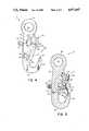
- FIG. 1is a perspective view of the instant invention illustrating the latch member in its first, latched position and the lock member in its first position.
- FIG. 2is a side elevation view of the instant invention, partially in section, illustrating the lock member in its second position.
- FIG. 3is a side elevation view of the instant invention, partially in section, illustrating the lock member in its second position and the latch member in its second, open position.
- FIG. 4is a side elevation view illustrating the lock member in an intermediate position, having been released by the user, with the latch member in its second, open position.
- FIG. 5is a sectional view taken along line 5--5 of FIG. 1.
- the double locking snap hook of the present inventionis generally indicated by reference numeral 10.
- the spring biased latch member 12 and spring biased lock member 14are both pivotally attached to shank 16.
- the shank 16has a first end 18 and a second end 20.
- the first end 18includes a return portion 22 defining a hook, the return portion 22 including a nose 24 spaced from the shank 16 to define a hook throat 26 (FIG. 3).
- the second end 20 of shank 16includes a means, such as an eyelet or O-ring 28, for attaining a load support member such as a safety harness, lanyard or the like.
- the spring biased latch member 12includes a bifurcated latch body 30 with opposed side walls which straddle hook shank 16.
- a biasing spring meanssuch as first spring 32 is contained within latch body 30 for urging latch member 12 into a first, latched position, shown if FIGS. 1 and 2.
- shank 16is provided with a spring retaining means such as a peg 33 for helping maintain spring 32 in the correct relative position.
- Latch member 12further includes a first end 34, pivotally mounted on shank 16 by pivot means such as latch member pin 36, and a second end 38 engageable with hook nose 24 to close hook throat 26. The latch member 12 is movable between the first, latched position, as indicated in FIGS.
- a thumb actuation means 39preferably in the form of a knurled pad, is mounted to or otherwise integral with rearwardly extending arms 29 and 31 of latch member 12. Thumb activation means 39 is mounted on the rear side of shank 16 so as to have the shank 16 intermediate thumb activation means 39 and the first and second ends 34, 38, respectively, of latch member 12.
- the spring biased locking means 14is also a bifurcated member comprised of a lock body 42 and legs, 41, 43 extending downwardly and rearwardly therefrom when snap hook 10 is oriented as shown in the accompanying drawings, in straddling relation to hook shank 16.
- Locking member 14is pivotally attached to shank 16 by pivot means such as pin 40 extending through the lower end of legs 41, 43.
- Locking member 14is attached adjacent hook throat 26 of return portion or hook 22 opposite nose 24, as best illustrated in FIGS. 3 and 5.
- Legs 41, 43 and lock body 42 of locking means 14are at least partially received within latch member 12, with legs 41, 43 passing through and extending beyond latch member 12. Locking means 14 releasably locks latch member 12 into its first, latched position, as most clearly indicated in FIG. 1.
- Locking means 14includes a spring means such as second spring 44 positioned within lock body 42 for urging locking member 14 into the locking position of FIG. 1 when latch member 12 is located in its first, latched position.
- Lock member 14is activated by the user by pressing finger pad 48 in a direction opposing second spring 44, thus displacing the lock member 14 to the position shown in FIG. 2.
- spring 44is retained within locking means 14 between shank 16 and finger pad 48 as illustrated in FIG. 5.
- lock body 42includes two locking ear projections 46, one of which is located on each side of snap hook 10. Ear projections 46 extend laterally outwardly from lock body 42 on opposite sides of shank 16 and engage the top edges of first, upper end 34 of latch member 12 to maintain it in its first, latched position.
- shank 16includes a forwardly protruding finger positioning segment or nub 50 projecting therefrom in the plane of the shank 16.
- Finger positioning segment 50is positioned adjacent the first end 34 of latch member 12 under lock member 14, opposing nose 24 of return portion 22.
- the front surface 35 of latch member 12terminates below the upper edges of its first end 34 in order to provide an opening through which segment 50 extends.
- the double locking snap hook 10may be grapsed in the palm of the user's hand with thumb activations means 39 positioned near the user's thumb.
- thumb activations means 39positioned near the user's thumb.
- the userIn order to either remove an item already fastened to the snap hook or fasten an item to the snap hook, the user must first displace lock member 14. This may be accomplished by pressing against finger pad surface 48, thus compressing second spring 44, as shown in FIG. 2.
- the finger pad surfacemay be easily located by the user by first finding the protruding finger positioning piece 50, which acts as a guide or reference point. The user may then move his or her finger to the appropriate position on the finger pad 48 without fear of inadvertently getting his or her finger caught in the latch member 12.
- lock member 14After displacing lock member 14, the user displaces latch member 12 by forcing thumb activation means 39 to the position shown in FIG. 3, compressing first spring 32. Lock member 14 may then be released by removing the finger from the finger pad 48, leaving the various components of snap hook 10 as shown in FIG. 4. The item to be removed from or attached to the snap hook 10 may then be passed through hook throat 26, and thumb activation means 39 may be released.
Landscapes
- Engineering & Computer Science (AREA)
- General Engineering & Computer Science (AREA)
- Mechanical Engineering (AREA)
- Emergency Lowering Means (AREA)
- Hooks, Suction Cups, And Attachment By Adhesive Means (AREA)
- Load-Engaging Elements For Cranes (AREA)
Abstract
Description
Claims (17)
Priority Applications (2)
| Application Number | Priority Date | Filing Date | Title |
|---|---|---|---|
| US07/427,716US4977647A (en) | 1989-10-27 | 1989-10-27 | Double locking snap hook |
| CA002027784ACA2027784C (en) | 1989-10-27 | 1990-10-16 | Double locking snap hook |
Applications Claiming Priority (1)
| Application Number | Priority Date | Filing Date | Title |
|---|---|---|---|
| US07/427,716US4977647A (en) | 1989-10-27 | 1989-10-27 | Double locking snap hook |
Publications (1)
| Publication Number | Publication Date |
|---|---|
| US4977647Atrue US4977647A (en) | 1990-12-18 |
Family
ID=23695964
Family Applications (1)
| Application Number | Title | Priority Date | Filing Date |
|---|---|---|---|
| US07/427,716Expired - LifetimeUS4977647A (en) | 1989-10-27 | 1989-10-27 | Double locking snap hook |
Country Status (2)
| Country | Link |
|---|---|
| US (1) | US4977647A (en) |
| CA (1) | CA2027784C (en) |
Cited By (49)
| Publication number | Priority date | Publication date | Assignee | Title |
|---|---|---|---|---|
| AU650371B2 (en)* | 1991-10-30 | 1994-06-16 | Moxham Industrial Pty. Ltd. | Dual latch safety hook |
| US5361464A (en)* | 1993-04-20 | 1994-11-08 | Bourdon Forge Company, Inc. | Double action snap hook |
| US5694668A (en)* | 1995-08-25 | 1997-12-09 | D B Industries, Inc. | Wall form hook assembly |
| US5735025A (en)* | 1996-09-25 | 1998-04-07 | United States Forgecraft Corporation | Ergonomic recessed release safety hook |
| GB2322402A (en)* | 1997-02-19 | 1998-08-26 | Doughty Engineering Limited | Lighting and sound equipment clamp for scaffolding |
| US5832571A (en)* | 1996-04-04 | 1998-11-10 | Yama Co., Ltd. | Joint member for use in accessory |
| US5842673A (en)* | 1996-05-17 | 1998-12-01 | Tumi Luggage, Inc. | Luggage hook strap |
| US5927431A (en)* | 1997-01-31 | 1999-07-27 | Klein, Jr.; Richard T. | Guarded snap hook |
| US6070308A (en)* | 1998-10-23 | 2000-06-06 | D B Industries, Inc. | Double locking snap hook |
| US6085802A (en)* | 1999-02-02 | 2000-07-11 | Silberberg; Abraham A. | Shock absorbing woven webbing |
| US6161264A (en)* | 1998-11-04 | 2000-12-19 | Soll Usa, Llc | Safety hook |
| US6363589B1 (en) | 2000-10-04 | 2002-04-02 | Aerial Machine & Tool Corporation | Rescue hook with safety locking mechanism |
| US20040094982A1 (en)* | 2002-11-18 | 2004-05-20 | Neufeldt Roy E. | Truss hook |
| US20040112936A1 (en)* | 2002-08-29 | 2004-06-17 | Tennessee Rand Co., Inc. | Wire clamp |
| US6832417B1 (en) | 2002-10-04 | 2004-12-21 | Gary E. Choate | Safety snap hook |
| EP1493710A1 (en)* | 2003-07-03 | 2005-01-05 | JT International Distributors, Inc. | Bullsnap |
| US6925690B2 (en) | 2003-07-07 | 2005-08-09 | Jt International Distributors Inc. | Bullsnap |
| US20070062014A1 (en)* | 2005-09-20 | 2007-03-22 | D B Industries, Inc. | Double locking snap hook |
| US20080185848A1 (en)* | 2007-02-07 | 2008-08-07 | Coulombe Don F | Safety hook |
| US20080184540A1 (en)* | 2007-02-07 | 2008-08-07 | Don F Coulombe | Safety hook |
| US20090066099A1 (en)* | 2002-11-18 | 2009-03-12 | Neufeldt Roy E | Truss hook |
| US7636990B1 (en) | 2008-03-25 | 2009-12-29 | Gary E Choate | Snap hook with hoop-loaded gate |
| US20100062028A1 (en)* | 2006-07-18 | 2010-03-11 | Cohen Joseph D | Vaccines for malaria |
| US20100199472A1 (en)* | 2009-02-10 | 2010-08-12 | Capital Safety Group (Australia) Pty Limited | Retrofittable hook device |
| US20100199471A1 (en)* | 2009-02-10 | 2010-08-12 | Capital Safety Group (Australia) Pty Limited | Retrofittable hook device |
| USD626908S1 (en)* | 2009-11-09 | 2010-11-09 | Aerial Machine & Tool Corp. | Helicopter hook |
| US20110138587A1 (en)* | 2009-12-11 | 2011-06-16 | Benjamin Walker | Multi-chamber carabiner |
| US8015676B1 (en)* | 2008-03-25 | 2011-09-13 | Reliance Industries, Llc | Snap hook with interlocking gate |
| US8622450B1 (en)* | 2012-02-22 | 2014-01-07 | Carl Mengel | Cam hook truss lift system |
| US8746766B2 (en) | 2012-06-07 | 2014-06-10 | Randy Lewkoski | Hook assembly |
| US8752254B2 (en) | 2012-02-28 | 2014-06-17 | D B Industries, Llc | Snap hook |
| GB2512106A (en)* | 2013-03-20 | 2014-09-24 | Maralin Safety Systems Ltd | Closable hook device |
| US9284162B2 (en) | 2012-12-20 | 2016-03-15 | Konecranes Plc | Lifting hook and safety latch for lifting hook |
| US9322428B2 (en) | 2013-03-01 | 2016-04-26 | D B Industries, Llc | Locking carabiner |
| US9320924B2 (en) | 2013-03-15 | 2016-04-26 | Honeywell International Inc. | Self-locking webbing connectable device attachment plate |
| US9500221B2 (en)* | 2015-03-25 | 2016-11-22 | Aerohook Technology Co., Ltd. | Triple locking hook connector |
| US20170073196A1 (en)* | 2014-03-10 | 2017-03-16 | Konecranes Global Corporation | Lifting hook, safety latch of lifting hook and locking and releasing device of safety latch |
| US9707419B2 (en) | 2014-10-08 | 2017-07-18 | D B Industries, Llc | Snap hook |
| CN107182205A (en)* | 2016-02-18 | 2017-09-19 | 株式会社永木精机 | safety hook |
| US10066659B2 (en)* | 2013-02-20 | 2018-09-04 | Sugatsune Kogyo Co., Ltd. | Hook |
| US10066660B2 (en) | 2015-10-22 | 2018-09-04 | Reliance Industries, Llc | Rebar snap hook |
| TWI641766B (en)* | 2017-05-05 | 2018-11-21 | 李錦旺 | One-sided safety hook |
| US20200062553A1 (en)* | 2018-08-27 | 2020-02-27 | John Toon | Double Locking Hook |
| US10647551B1 (en)* | 2018-10-25 | 2020-05-12 | Ulven Forging Incorporated | Rope hook assembly having a latch member |
| US11142432B2 (en)* | 2019-02-12 | 2021-10-12 | Pewag Austria Gmbh | Safety load hook |
| US11148911B2 (en)* | 2019-02-07 | 2021-10-19 | The Crosby Group LLC | Positive locking latch assembly for hook |
| US20220275825A1 (en)* | 2019-08-30 | 2022-09-01 | Rud Ketten Rieger & Dietz Gmbh U. Co. Kg | Underwater hook with actuation button and release button |
| US11629750B1 (en) | 2021-12-14 | 2023-04-18 | Sherrill, Inc. | Double locking snap hook |
| US11898591B2 (en) | 2021-08-29 | 2024-02-13 | Make Ideas, LLC | Releasable coupling device |
Citations (26)
| Publication number | Priority date | Publication date | Assignee | Title |
|---|---|---|---|---|
| US939727A (en)* | 1909-10-04 | 1909-11-09 | Matti Maki | Snap-hook. |
| US1289096A (en)* | 1917-12-03 | 1918-12-31 | Jacob Boatright | Safety-hook. |
| US1626866A (en)* | 1926-10-30 | 1927-05-03 | Robert E Neilson | Safety hook |
| US1711346A (en)* | 1928-02-23 | 1929-04-30 | Edgar E Greve | Safety hook |
| US1879168A (en)* | 1931-07-10 | 1932-09-27 | North & Judd Mfg Co | Safety snap hook |
| US1949608A (en)* | 1931-07-17 | 1934-03-06 | Mathias Klein & Sons | Safety hook |
| US2490931A (en)* | 1947-03-12 | 1949-12-13 | Albert N Thompson | Self-locking device for linemen's body belts |
| GB798247A (en)* | 1955-10-11 | 1958-07-16 | United States Steel Corp | Safety lock for crane hook |
| US3918758A (en)* | 1974-07-18 | 1975-11-11 | Aeroquip Corp | Remotely releasable self-latching snap hook |
| US4062092A (en)* | 1975-07-11 | 1977-12-13 | Fujii Denko Company, Limited | Safety hook |
| US4320561A (en)* | 1978-12-16 | 1982-03-23 | Eisen- Und Drahtwerk Erlau Aktiengesellschaft | Hook, especially safety load hook |
| US4333212A (en)* | 1978-11-17 | 1982-06-08 | Bibollet Jean Claude | Snap-hook, particularly for mountaineering |
| US4372016A (en)* | 1980-07-03 | 1983-02-08 | Gulf & Western Manufacturing Company | Hardware snap and method of producing same |
| US4379579A (en)* | 1981-12-16 | 1983-04-12 | The B. F. Goodrich Company | Automatic locking and ejecting hook assembly |
| US4401333A (en)* | 1981-08-31 | 1983-08-30 | Schaefer Marine, Inc. | Pelican hook |
| US4434536A (en)* | 1982-10-13 | 1984-03-06 | Rose Manufacturing Company | Locking snap hook |
| US4440432A (en)* | 1982-02-22 | 1984-04-03 | The Crosby Group, Inc. | Self-locking, quick release, latched hook |
| US4528728A (en)* | 1982-10-13 | 1985-07-16 | Rose Manufacturing Company | Locking snap hook |
| US4528729A (en)* | 1983-08-26 | 1985-07-16 | Rose Manufacturing Company | Locking snap hook |
| US4539732A (en)* | 1984-01-30 | 1985-09-10 | D B Industries, Inc. | Double locking safety snap |
| US4546523A (en)* | 1983-12-19 | 1985-10-15 | United States Forgecraft Corporation | Safety hook construction |
| US4554712A (en)* | 1982-08-06 | 1985-11-26 | Le Beon Roger M | Safety hooks |
| US4621851A (en)* | 1985-11-27 | 1986-11-11 | United States Forgecraft Corporation | Safety hook |
| US4645255A (en)* | 1978-06-16 | 1987-02-24 | Zepf Hans R | Load hook |
| US4731910A (en)* | 1987-06-22 | 1988-03-22 | Purcell Elmor G | Hooking mechanism |
| US4767144A (en)* | 1985-06-19 | 1988-08-30 | Hoernberg Gunnar | Hook assembly |
- 1989
- 1989-10-27USUS07/427,716patent/US4977647A/ennot_activeExpired - Lifetime
- 1990
- 1990-10-16CACA002027784Apatent/CA2027784C/ennot_activeExpired - Lifetime
Patent Citations (26)
| Publication number | Priority date | Publication date | Assignee | Title |
|---|---|---|---|---|
| US939727A (en)* | 1909-10-04 | 1909-11-09 | Matti Maki | Snap-hook. |
| US1289096A (en)* | 1917-12-03 | 1918-12-31 | Jacob Boatright | Safety-hook. |
| US1626866A (en)* | 1926-10-30 | 1927-05-03 | Robert E Neilson | Safety hook |
| US1711346A (en)* | 1928-02-23 | 1929-04-30 | Edgar E Greve | Safety hook |
| US1879168A (en)* | 1931-07-10 | 1932-09-27 | North & Judd Mfg Co | Safety snap hook |
| US1949608A (en)* | 1931-07-17 | 1934-03-06 | Mathias Klein & Sons | Safety hook |
| US2490931A (en)* | 1947-03-12 | 1949-12-13 | Albert N Thompson | Self-locking device for linemen's body belts |
| GB798247A (en)* | 1955-10-11 | 1958-07-16 | United States Steel Corp | Safety lock for crane hook |
| US3918758A (en)* | 1974-07-18 | 1975-11-11 | Aeroquip Corp | Remotely releasable self-latching snap hook |
| US4062092A (en)* | 1975-07-11 | 1977-12-13 | Fujii Denko Company, Limited | Safety hook |
| US4645255A (en)* | 1978-06-16 | 1987-02-24 | Zepf Hans R | Load hook |
| US4333212A (en)* | 1978-11-17 | 1982-06-08 | Bibollet Jean Claude | Snap-hook, particularly for mountaineering |
| US4320561A (en)* | 1978-12-16 | 1982-03-23 | Eisen- Und Drahtwerk Erlau Aktiengesellschaft | Hook, especially safety load hook |
| US4372016A (en)* | 1980-07-03 | 1983-02-08 | Gulf & Western Manufacturing Company | Hardware snap and method of producing same |
| US4401333A (en)* | 1981-08-31 | 1983-08-30 | Schaefer Marine, Inc. | Pelican hook |
| US4379579A (en)* | 1981-12-16 | 1983-04-12 | The B. F. Goodrich Company | Automatic locking and ejecting hook assembly |
| US4440432A (en)* | 1982-02-22 | 1984-04-03 | The Crosby Group, Inc. | Self-locking, quick release, latched hook |
| US4554712A (en)* | 1982-08-06 | 1985-11-26 | Le Beon Roger M | Safety hooks |
| US4434536A (en)* | 1982-10-13 | 1984-03-06 | Rose Manufacturing Company | Locking snap hook |
| US4528728A (en)* | 1982-10-13 | 1985-07-16 | Rose Manufacturing Company | Locking snap hook |
| US4528729A (en)* | 1983-08-26 | 1985-07-16 | Rose Manufacturing Company | Locking snap hook |
| US4546523A (en)* | 1983-12-19 | 1985-10-15 | United States Forgecraft Corporation | Safety hook construction |
| US4539732A (en)* | 1984-01-30 | 1985-09-10 | D B Industries, Inc. | Double locking safety snap |
| US4767144A (en)* | 1985-06-19 | 1988-08-30 | Hoernberg Gunnar | Hook assembly |
| US4621851A (en)* | 1985-11-27 | 1986-11-11 | United States Forgecraft Corporation | Safety hook |
| US4731910A (en)* | 1987-06-22 | 1988-03-22 | Purcell Elmor G | Hooking mechanism |
Cited By (71)
| Publication number | Priority date | Publication date | Assignee | Title |
|---|---|---|---|---|
| AU650371B2 (en)* | 1991-10-30 | 1994-06-16 | Moxham Industrial Pty. Ltd. | Dual latch safety hook |
| US5361464A (en)* | 1993-04-20 | 1994-11-08 | Bourdon Forge Company, Inc. | Double action snap hook |
| US5694668A (en)* | 1995-08-25 | 1997-12-09 | D B Industries, Inc. | Wall form hook assembly |
| US5832571A (en)* | 1996-04-04 | 1998-11-10 | Yama Co., Ltd. | Joint member for use in accessory |
| US5842673A (en)* | 1996-05-17 | 1998-12-01 | Tumi Luggage, Inc. | Luggage hook strap |
| US5735025A (en)* | 1996-09-25 | 1998-04-07 | United States Forgecraft Corporation | Ergonomic recessed release safety hook |
| US5927431A (en)* | 1997-01-31 | 1999-07-27 | Klein, Jr.; Richard T. | Guarded snap hook |
| GB2322402A (en)* | 1997-02-19 | 1998-08-26 | Doughty Engineering Limited | Lighting and sound equipment clamp for scaffolding |
| US6070308A (en)* | 1998-10-23 | 2000-06-06 | D B Industries, Inc. | Double locking snap hook |
| US6161264A (en)* | 1998-11-04 | 2000-12-19 | Soll Usa, Llc | Safety hook |
| US6085802A (en)* | 1999-02-02 | 2000-07-11 | Silberberg; Abraham A. | Shock absorbing woven webbing |
| US6363589B1 (en) | 2000-10-04 | 2002-04-02 | Aerial Machine & Tool Corporation | Rescue hook with safety locking mechanism |
| US20040112936A1 (en)* | 2002-08-29 | 2004-06-17 | Tennessee Rand Co., Inc. | Wire clamp |
| US6832417B1 (en) | 2002-10-04 | 2004-12-21 | Gary E. Choate | Safety snap hook |
| US7422257B2 (en) | 2002-11-18 | 2008-09-09 | Neufeldt Roy E | Truss gripping hook |
| US20090066099A1 (en)* | 2002-11-18 | 2009-03-12 | Neufeldt Roy E | Truss hook |
| US20040094982A1 (en)* | 2002-11-18 | 2004-05-20 | Neufeldt Roy E. | Truss hook |
| US7059644B2 (en)* | 2002-11-18 | 2006-06-13 | Neufeldt Roy E | Truss gripping hook |
| US20060208514A1 (en)* | 2002-11-18 | 2006-09-21 | Neufeldt Roy E | Truss hook |
| EP1493710A1 (en)* | 2003-07-03 | 2005-01-05 | JT International Distributors, Inc. | Bullsnap |
| US6925690B2 (en) | 2003-07-07 | 2005-08-09 | Jt International Distributors Inc. | Bullsnap |
| US20070062014A1 (en)* | 2005-09-20 | 2007-03-22 | D B Industries, Inc. | Double locking snap hook |
| WO2007035263A1 (en)* | 2005-09-20 | 2007-03-29 | D B Industries, Inc. | Double locking snap hook |
| US7647677B2 (en)* | 2005-09-20 | 2010-01-19 | D B Industries, Inc. | Double locking snap hook |
| US20100062028A1 (en)* | 2006-07-18 | 2010-03-11 | Cohen Joseph D | Vaccines for malaria |
| US20080184540A1 (en)* | 2007-02-07 | 2008-08-07 | Don F Coulombe | Safety hook |
| US7922220B2 (en)* | 2007-02-07 | 2011-04-12 | Coulombe Don F | Safety hook |
| US20080185848A1 (en)* | 2007-02-07 | 2008-08-07 | Coulombe Don F | Safety hook |
| US8007015B2 (en)* | 2007-02-07 | 2011-08-30 | Coulombe Don F | Safety hook |
| US8015676B1 (en)* | 2008-03-25 | 2011-09-13 | Reliance Industries, Llc | Snap hook with interlocking gate |
| US7636990B1 (en) | 2008-03-25 | 2009-12-29 | Gary E Choate | Snap hook with hoop-loaded gate |
| US20100199471A1 (en)* | 2009-02-10 | 2010-08-12 | Capital Safety Group (Australia) Pty Limited | Retrofittable hook device |
| US20100199472A1 (en)* | 2009-02-10 | 2010-08-12 | Capital Safety Group (Australia) Pty Limited | Retrofittable hook device |
| US8181313B2 (en) | 2009-02-10 | 2012-05-22 | Capital Safety Group (Australia) Pty Limited | Retrofittable hook device |
| US8186023B2 (en) | 2009-02-10 | 2012-05-29 | Capital Safety Group (Australia) Pty Limited | Retrofittable hook device |
| USD626908S1 (en)* | 2009-11-09 | 2010-11-09 | Aerial Machine & Tool Corp. | Helicopter hook |
| US20110138587A1 (en)* | 2009-12-11 | 2011-06-16 | Benjamin Walker | Multi-chamber carabiner |
| US9003617B2 (en) | 2009-12-11 | 2015-04-14 | Black Diamond Equipment Ltd. | Multi-chamber carabiner |
| US8622450B1 (en)* | 2012-02-22 | 2014-01-07 | Carl Mengel | Cam hook truss lift system |
| US9328765B2 (en) | 2012-02-28 | 2016-05-03 | D B Industries, Llc | Snap hook |
| US8752254B2 (en) | 2012-02-28 | 2014-06-17 | D B Industries, Llc | Snap hook |
| US8746766B2 (en) | 2012-06-07 | 2014-06-10 | Randy Lewkoski | Hook assembly |
| US9284162B2 (en) | 2012-12-20 | 2016-03-15 | Konecranes Plc | Lifting hook and safety latch for lifting hook |
| US10066659B2 (en)* | 2013-02-20 | 2018-09-04 | Sugatsune Kogyo Co., Ltd. | Hook |
| US9322428B2 (en) | 2013-03-01 | 2016-04-26 | D B Industries, Llc | Locking carabiner |
| US9320924B2 (en) | 2013-03-15 | 2016-04-26 | Honeywell International Inc. | Self-locking webbing connectable device attachment plate |
| GB2512106B (en)* | 2013-03-20 | 2019-04-03 | Maralin Safety Systems Ltd | Closable hook device |
| GB2512106A (en)* | 2013-03-20 | 2014-09-24 | Maralin Safety Systems Ltd | Closable hook device |
| US20170073196A1 (en)* | 2014-03-10 | 2017-03-16 | Konecranes Global Corporation | Lifting hook, safety latch of lifting hook and locking and releasing device of safety latch |
| US9776835B2 (en)* | 2014-03-10 | 2017-10-03 | Konecranes Global Corporation | Lifting hook, safety latch of lifting hook and locking and releasing device of safety latch |
| US9707419B2 (en) | 2014-10-08 | 2017-07-18 | D B Industries, Llc | Snap hook |
| US10086221B2 (en) | 2014-10-08 | 2018-10-02 | D B Industries, Llc | Snap hook |
| US9500221B2 (en)* | 2015-03-25 | 2016-11-22 | Aerohook Technology Co., Ltd. | Triple locking hook connector |
| US10066660B2 (en) | 2015-10-22 | 2018-09-04 | Reliance Industries, Llc | Rebar snap hook |
| KR20170106183A (en)* | 2016-02-18 | 2017-09-20 | 가부시키가이샤나가키세이키 | Safety hook |
| EP3228361A4 (en)* | 2016-02-18 | 2018-03-14 | Nagaki Seiki Co., Ltd. | Safety hook |
| AU2016393022B2 (en)* | 2016-02-18 | 2018-12-13 | Nagaki Seiki Co., Ltd. | Safety hook |
| CN107182205A (en)* | 2016-02-18 | 2017-09-19 | 株式会社永木精机 | safety hook |
| US10352349B2 (en) | 2016-02-18 | 2019-07-16 | Nagaki Seiki Co., Ltd. | Safety hook |
| CN111059133B (en)* | 2016-02-18 | 2021-09-10 | 株式会社永木精机 | Safety hook |
| CN111059133A (en)* | 2016-02-18 | 2020-04-24 | 株式会社永木精机 | Safety hook |
| TWI641766B (en)* | 2017-05-05 | 2018-11-21 | 李錦旺 | One-sided safety hook |
| US10882721B2 (en)* | 2018-08-27 | 2021-01-05 | John Toon | Double locking hook |
| US20200062553A1 (en)* | 2018-08-27 | 2020-02-27 | John Toon | Double Locking Hook |
| US10647551B1 (en)* | 2018-10-25 | 2020-05-12 | Ulven Forging Incorporated | Rope hook assembly having a latch member |
| US11148911B2 (en)* | 2019-02-07 | 2021-10-19 | The Crosby Group LLC | Positive locking latch assembly for hook |
| US11142432B2 (en)* | 2019-02-12 | 2021-10-12 | Pewag Austria Gmbh | Safety load hook |
| US20220275825A1 (en)* | 2019-08-30 | 2022-09-01 | Rud Ketten Rieger & Dietz Gmbh U. Co. Kg | Underwater hook with actuation button and release button |
| US12366262B2 (en)* | 2019-08-30 | 2025-07-22 | Rud Ketten Rieger & Dietz Gmbh U. Co. Kg | Underwater hook with actuation button and release button |
| US11898591B2 (en) | 2021-08-29 | 2024-02-13 | Make Ideas, LLC | Releasable coupling device |
| US11629750B1 (en) | 2021-12-14 | 2023-04-18 | Sherrill, Inc. | Double locking snap hook |
Also Published As
| Publication number | Publication date |
|---|---|
| CA2027784C (en) | 1994-12-27 |
| CA2027784A1 (en) | 1991-04-28 |
Similar Documents
| Publication | Publication Date | Title |
|---|---|---|
| US4977647A (en) | Double locking snap hook | |
| US4122585A (en) | Single-action double-lock snap | |
| US5735025A (en) | Ergonomic recessed release safety hook | |
| US5257441A (en) | Triple locking snap hook | |
| US5177837A (en) | Strap attachment for luggage and the like | |
| US5926959A (en) | Locking knife and sheath | |
| US5810221A (en) | Handgun holster having a trigger guard retainer latch | |
| US7107657B1 (en) | Lanyard operated sternum breakaway buckle with vertical position adjustment | |
| US6601274B2 (en) | Static line snap | |
| US3986234A (en) | Releasable fastener | |
| US5265696A (en) | Ladder climbing safety clamp | |
| US4932362A (en) | One finger quick release animal collar | |
| US3686715A (en) | Strap system for material handling | |
| SU1102482A3 (en) | Buckle for safety belt | |
| US4546523A (en) | Safety hook construction | |
| US5002213A (en) | Harness knife and sheath | |
| US2722449A (en) | Releasable fastenings for coupling or latching together two relatively movable members | |
| US3110071A (en) | Belt buckle | |
| US4309052A (en) | Safety hook | |
| US3008210A (en) | Safety crane hooks | |
| US8984725B2 (en) | Buckle mechanism | |
| US4570574A (en) | Cage door for easy one-hand operation | |
| US4937923A (en) | Positive-lock quick-release buckle | |
| KR900010257Y1 (en) | Slider for slide fastener | |
| CA2397269C (en) | Snap connector |
Legal Events
| Date | Code | Title | Description |
|---|---|---|---|
| AS | Assignment | Owner name:D.B. INDUSTRIES, INC., 3965 PEPIN AVENUE, P.O. BOX Free format text:ASSIGNMENT OF ASSIGNORS INTEREST.;ASSIGNOR:CASEBOLT, SCOTT C.;REEL/FRAME:005187/0079 Effective date:19891106 | |
| STCF | Information on status: patent grant | Free format text:PATENTED CASE | |
| FPAY | Fee payment | Year of fee payment:4 | |
| FPAY | Fee payment | Year of fee payment:8 | |
| AS | Assignment | Owner name:D B INDUSTRIES, INC., MINNESOTA Free format text:CORRECTIVE ASSIGNMENT TO CORRECT THE CORPORATE IDENTITY OF THE RECEIVING PARTY. AN ASSIGNMENT PREVIOUSLY RECORDED AT REEL 5187, FRAME 0079;ASSIGNOR:CASEBOLT, SCOTT C.;REEL/FRAME:010340/0142 Effective date:19891106 | |
| FEPP | Fee payment procedure | Free format text:PAYOR NUMBER ASSIGNED (ORIGINAL EVENT CODE: ASPN); ENTITY STATUS OF PATENT OWNER: LARGE ENTITY | |
| FPAY | Fee payment | Year of fee payment:12 | |
| AS | Assignment | Owner name:BARCLAYS BANK PLC,UNITED KINGDOM Free format text:SECURITY AGREEMENT;ASSIGNORS:CAPITAL SAFETY INC.;D B INDUSTRIES, INC.;SINCO, INC.;REEL/FRAME:016621/0445 Effective date:20051005 Owner name:BARCLAYS BANK PLC, UNITED KINGDOM Free format text:SECURITY AGREEMENT;ASSIGNORS:CAPITAL SAFETY INC.;D B INDUSTRIES, INC.;SINCO, INC.;REEL/FRAME:016621/0445 Effective date:20051005 | |
| AS | Assignment | Owner name:CAPITAL SAFETY GROUP LIMITED, UNITED KINGDOM Free format text:RELEASE BY SECURED PARTY;ASSIGNOR:BARCLAYS BANK PLC;REEL/FRAME:019562/0146 Effective date:20070615 Owner name:CAPITAL SAFETY INC., MINNESOTA Free format text:RELEASE BY SECURED PARTY;ASSIGNOR:BARCLAYS BANK PLC;REEL/FRAME:019562/0146 Effective date:20070615 Owner name:D B INDUSTRIES, INC., MINNESOTA Free format text:RELEASE BY SECURED PARTY;ASSIGNOR:BARCLAYS BANK PLC;REEL/FRAME:019562/0146 Effective date:20070615 Owner name:SINCO, INC., MINNESOTA Free format text:RELEASE BY SECURED PARTY;ASSIGNOR:BARCLAYS BANK PLC;REEL/FRAME:019562/0146 Effective date:20070615 Owner name:CAPITAL SAFETY GROUP LIMITED,UNITED KINGDOM Free format text:RELEASE BY SECURED PARTY;ASSIGNOR:BARCLAYS BANK PLC;REEL/FRAME:019562/0146 Effective date:20070615 Owner name:CAPITAL SAFETY INC.,MINNESOTA Free format text:RELEASE BY SECURED PARTY;ASSIGNOR:BARCLAYS BANK PLC;REEL/FRAME:019562/0146 Effective date:20070615 Owner name:D B INDUSTRIES, INC.,MINNESOTA Free format text:RELEASE BY SECURED PARTY;ASSIGNOR:BARCLAYS BANK PLC;REEL/FRAME:019562/0146 Effective date:20070615 Owner name:SINCO, INC.,MINNESOTA Free format text:RELEASE BY SECURED PARTY;ASSIGNOR:BARCLAYS BANK PLC;REEL/FRAME:019562/0146 Effective date:20070615 | |
| AS | Assignment | Owner name:THE GOVERNOR AND THE COMPANY OF THE BANK OF SCOTLA Free format text:SECURITY AGREEMENT;ASSIGNORS:CAPITAL SAFETY INC.;D B INDUSTRIES, INC.;REEL/FRAME:019658/0069 Effective date:20070704 | |
| AS | Assignment | Owner name:D B INDUSTRIES, INC., MINNESOTA Free format text:RELEASE OF SECURITY INTEREST R/F 019658/0069;ASSIGNOR:BANK OF SCOTLAND PLC (FORMERLY KNOWN AS THE GOVERNOR AND THE COMPANY OF THE BANK OF SCOTLAND);REEL/FRAME:027631/0727 Effective date:20120119 Owner name:CAPITAL SAFETY, INC., MINNESOTA Free format text:RELEASE OF SECURITY INTEREST R/F 019658/0069;ASSIGNOR:BANK OF SCOTLAND PLC (FORMERLY KNOWN AS THE GOVERNOR AND THE COMPANY OF THE BANK OF SCOTLAND);REEL/FRAME:027631/0727 Effective date:20120119 |