US4977509A - Personal multi-purpose navigational apparatus and method for operation thereof - Google Patents
Personal multi-purpose navigational apparatus and method for operation thereofDownload PDFInfo
- Publication number
- US4977509A US4977509AUS07/357,843US35784389AUS4977509AUS 4977509 AUS4977509 AUS 4977509AUS 35784389 AUS35784389 AUS 35784389AUS 4977509 AUS4977509 AUS 4977509A
- Authority
- US
- United States
- Prior art keywords
- instrument
- operating
- navigational
- information
- processing unit
- Prior art date
- Legal status (The legal status is an assumption and is not a legal conclusion. Google has not performed a legal analysis and makes no representation as to the accuracy of the status listed.)
- Expired - Fee Related
Links
Images


Classifications
- G—PHYSICS
- G01—MEASURING; TESTING
- G01C—MEASURING DISTANCES, LEVELS OR BEARINGS; SURVEYING; NAVIGATION; GYROSCOPIC INSTRUMENTS; PHOTOGRAMMETRY OR VIDEOGRAMMETRY
- G01C21/00—Navigation; Navigational instruments not provided for in groups G01C1/00 - G01C19/00
- G01C21/20—Instruments for performing navigational calculations
- G—PHYSICS
- G06—COMPUTING OR CALCULATING; COUNTING
- G06F—ELECTRIC DIGITAL DATA PROCESSING
- G06F15/00—Digital computers in general; Data processing equipment in general
- G06F15/02—Digital computers in general; Data processing equipment in general manually operated with input through keyboard and computation using a built-in program, e.g. pocket calculators
- G06F15/025—Digital computers in general; Data processing equipment in general manually operated with input through keyboard and computation using a built-in program, e.g. pocket calculators adapted to a specific application
Definitions
- This inventiongenerally relates to a personal multipurpose navigational apparatus for use generally in numerous activities. More particularly, the invention relates to a personal multi-purpose navigational device having the capabilities of providing numerous navigational information, including direction, orientation, barometric pressure, temperature, current and elapse times, angles, distances, estimated time of arrival, altitude, inclination, declination, general weather conditions, location of "hot” bodies, or the like.
- a compact and portable deviceis essential in providing required or important information for use in industry, military, or the like.
- a navigational instrument capable of providing a plurality of informationis essential in order to avoid experiencing any problems in these activities and, in most instances, a navigational instrument is essential in obtaining the activities' goals.
- the use of a compact and portable navigational instrument capable of providing a multitude of essential informationenhances the user's involvement in these activities.
- a personal multi-purpose navigational apparatus or instrumentwhich is portable, compact, lightweight, durable and capable of providing a multitude of navigational information and other information on the user's environment.
- a personal multi-purpose navigational instrumentshould have sufficient rigidity and durability capable of being used in the worst environmental conditions of different types of activities, such as, sailing, orienteering, backpacking, fishing, forestry, surveying, geology, infantry, survival and rescue activities, or the like.
- the personal multi-purpose navigational instrumentshould be made of lightweight materials so as to be easily carried at long distances and at rugged terrain.
- the personal multi-purpose navigational instrumentshould further be well suited for communicating with external electronic instruments in order to more fully serve the user.
- a personal multi-purpose navigational instrumentfor use in a multitude of activities.
- a multipurpose keyboardwhich communicates with an internal microprocessor allows the user to communicate with the instrument for providing any desired navigational information.
- the instrumentincludes the immediate display of navigational information in digital form and digital bearing read-out from a flux gate sensor within the instrument. Determination of a corresponding course heading and the storage of the corresponding bearing, can be performed in the navigational instrument of the instant invention.
- the navigational instrumentis provided with top and bottom casings for mounting thereon an LCD display for reading therefrom the navigational information.
- the navigational instrumentpreferably has an automatic or user-definable liquid crystal display contrast function which is dependent on measured surrounding or internal temperature.
- the navigational instrumenthas a lighting mechanism for night use which may be set to automatically engage when the user activates the navigational instrument for specific period of time during the day or a lighting mechanism which can be manually engaged.
- a keyboardis operably mounted onto the top casing in order for the user to conveniently communicate with the microprocessor therein. Numerous functions can be performed as desired by way of the operations performed by the user on the keyboard; i.e., by way of specifically operating the multiple keys or buttons on the keyboard in various specific steps in order to achieve, for display or the like, the desired navigational information.
- a freeze switchis operably mounted within the casings for allowing any information outputted on the LCD display to be held for convenient and easy reading by the user.
- a pop-up lensis incorporated within the front portion of the instrument for allowing the user to simultaneously observe a target sight and navigational information displayed on the LCD display.
- a scaled protractor having fold-down capabilitiesis further operationally integrated within the body of the instrument for providing essential information with a map during navigation.
- An input/output port portionis further provided on a side portion of the instrument for allowing another microprocessor or an external electronic instrument to be operably connected to the internal microprocessor for allowing the internal microprocessor to communicate with the external microprocessor or the external electronic instrument.
- a flux gate, barometric sensor, temperature sensor and infrared sensorare all incorporated within the instrument and operably integrated within the internal microprocessor.
- FIG. 1is a top view of the fully assembled personal multi-purpose navigational instrument in accordance with the present invention showing the protractor scale, LCD display, keyboard and pop-up lens;
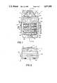
- FIG. 2is an elevational view showing a rear end portion of the personal multi-purpose navigational instrument of the instant invention showing the LCD display in its upstanding position;
- FIG. 3is a left side elevational view of the personal multi-purpose navigational instrument of the instant invention showing the freeze switch, extending side portion of the protracted scale, upstanding side portion of the LCD display, and the upstanding position of the pop-up lens;
- FIG. 4is a front end elevational view of the navigational instrument showing a folded up protractor and graduated scale.
- FIG. 5is a perspective exploded view of the personal multi-purpose navigational instrument of the instant invention.
- FIG. 6is a cross-sectional view taken along line 6--6 of FIG. 1 showing the manner in which the internal components of the personal multi-purpose navigational instrument of the instant invention is effectively and compactly arranged within the upper and lower casings;
- FIG. 7is a block diagram showing the manner in which the different structures of the personal multi-purpose navigational instrument of the instant invention are operably connected to each other;
- FIG. 8is a flow chart showing the manner in which the personal multi-purpose navigational instrument is operated.
- FIG. 9Ais a flow chart more particularly showing the manner in which the real time clock interrupt handler is operated, while FIG. 9B is a flow chart more particularly showing the manner in which the keyboard interrupt handler is operated;
- FIG. 10is a flow chart which more specifically illustrates the manner in which the display manager, shown in FIG. 8, is operated.
- FIG. 11is a flow chart more particularly showing the manner in which the task manager, shown in FIG. 8, is operated.
- FIG. 1shows the top elevational view of the personal multi-purpose navigational instrument (hereinafter, "navigational instrument"), generally designated by reference No. 1, showing a protractor scale 3, an LCD display 5, a keyboard 7, and a pop-up lens 9.
- the protractor and graduated scale 3is one which can preferably be folded up or down (see, e.g., FIG. 3) and is preferably made of clear plastic material or the like.
- the protractor and graduated scale 3is also preferably in the form of clear plastic plate etched with a protractor and graduated scale 3 for map use, or the like.
- the LCD display 5is also preferably one which can be folded up or down (see, FIGS. 3 and 6).
- the LCD display 5is used for displaying information desired by a user (such as, barometric pressure, temperature, bearings, inclination/declination, current time, elapse time, or the like).
- the keyboard 7allows a user to input or output any of the above-described information in a manner which will later be more fully discussed.
- the pop-up lens 9is more fully shown in FIGS. 2-4.
- the pop-up lens 9in its upstanding position allows a user to sight an object and simultaneously read the bearing information from the LCD display 5, either at daytime or at night time.
- a forward sight portion 11In line with the pop-up lens 9, is a forward sight portion 11 preferably integral to the top portion of the LCD display 5.
- the navigational instrument 1is enclosed by upper 14 and lower 16 casings. Located at the bottom rear end portion of the lower casings 16 are battery doors 18. It is preferable that the upper 14 and lower 16 casings are made of sturdy and long-lasting materials and are fitted together so as to allow the navigational instrument 1 to be used in the most hostile environment (e.g., constant vibrations due to rugged terrain, water resistant due to weather conditions, extreme hot and cold weather conditions, or the like). On one side of the navigational instrument 1 is a freeze switch 20 which permits a user to hold or freeze any information displayed on the LCD display 5; thereby allowing the information to be conveniently and readily read by the user.
- a freeze switch 20which permits a user to hold or freeze any information displayed on the LCD display 5; thereby allowing the information to be conveniently and readily read by the user.
- an input/output port 22for allowing another instrument (such as, an external electronic instrument, microprocessor, or the like) to communicate with an internal microprocessor, later to be discussed, of the navigational instrument 1, or vice versa.
- another instrumentsuch as, an external electronic instrument, microprocessor, or the like
- FIG. 3Shown in FIG. 3 are the structural and operational relationships of the extended or upstanding protractor and graduated scale 3, LCD display 5, and pop-up lens 9.
- FIG. 4illustrates the front end view of the navigational instrument 1 when the protractor and graduated scale 3 is folded up for abutting the front end side portion of the navigational instrument 1.
- the protractor and graduated scale 3preferably has apertures 24, 26 passing therethrough.
- the apertures 24, 26are provided for allowing a temperature sensor 28 and an infrared sensor 30 to outwardly extend from the front end side of the navigational instrument 1.
- the LCD display 5is preferably hinged to the upper casing 14 for allowing it to take on upstanding position or a position which allows it to be accommodated within the elongated indented portion 32 of the upper casing 14.
- the LCD display 5has connecting wires 34 for connecting to an internal microprocessor 40.
- the upper casing 14has an enlarged opening 42 passing therethrough for accommodating the keyboard 7 therein.
- the upper casingfurther has substantially semicircular shaped openings 44, 46 for accommodating therein portions of the freeze switch 20 and the inlet/outlet port 22, respectively.
- a substantially rectangular opening 48also passes through the front portion of the upper casing 14 for accommodating therein the pop-up lens 9 during its upstanding position.
- the lower casing 16also has substantially semicircular shaped openings 50, 52 for accommodating therein portions of the freeze switch 20 and the input/output port 22, respectively.
- the lower casing 16further has an upstanding channel 54 for accommodating therein the pop-up lens 9.
- the lower casing 16further has a back side portion having mounted thereon guide members (such as, guide tubes, or the like) 58, 60 for mounting thereon the temperature sensor 28 and the infrared sensor 30, respectively.
- the infrared sensor 30is operably connected to a generator (not shown) which is operably connected to a microprocessor 40 for driving the infrared sensor 30 by way of the microprocessor 40.
- a dish-like member 64having a perforated bottom portion 66 passing through the base side 62 of the lower casing for accommodating thereon a barometric pressure sensor 68.
- the barometric pressure sensor 68is preferably one which is of a solid state type.
- a lanyard rod 55is lodged within a groove portion 57 of the lower casing 16 for allowing a strap (not shown) to be coupled for use when carrying the instrument 1.
- a microprocessor 40having a read only memory (ROM) portion for housing the microprocessor software and a random access memory (RAM) for storing data and programs.
- the microprocessor 40is preferably an "INTEL" 8031 type, or the like.
- a flux gate magnetometer 70in a circuit board 72 having an X and Y output being on an orthogonal relationship with each other.
- the flux gate magnetometer 70provides azimuth information, along with other navigational information, which are then translated and stored for outputting to the LCD display 5 from a user's instructions through the keyboard 7.
- the flux gate magnetometer 70is preferably that of a solid state device.
- FIG. 7The manner in which the above-described components are connected to each other is illustrated in FIG. 7 and are shown in FIG. 6 to be arranged in a very compact manner inside the upper 14 and lower 16 casings.
- the battery 15, for power supply encased within the battery door 18is connected to an analog multiplexer 80.
- the temperature sensor 28, infrared sensor 30, barometric sensor 68, and the flux gate magnetometer 70are all operably coupled to the analog multiplexer 80.
- the analog multiplexer 80is directly connected to a serial analog-to-digital converter 84 which is, in turn, operably connected to the central processing (CPU) 88 of the microprocessor 40.
- the CPU 88preferably has a random access memory (RAM) 90.
- RAMrandom access memory
- the CPU 88preferably has a read only memory (ROM), timers, serial unit, and master oscillator (not shown).
- the input/output port 22 for serial interfacing with other electronic equipment, computers, or the like,is also directly connected to the CPU 88.
- the keyboard 7is operably joined to a keyboard interface 92 for directly coupling to the CPU 88.
- the display 5is also directly operably joined to the CPU 88.
- the freeze button 20is also operably connected to the CPU 88 for momentarily halting or freezing the display of information on the LCD display 5; thereby, allowing the displayed information to be conveniently and readily read by the user.
- the instrument 1queries the user for the correct time and date, and from there, the microprocessor 40 proceeds to maintain the current time through the use of software and internal counter timers within the CPU.
- the analog-to-digital converteris used by the software for constantly monitoring bearing signals, temperature signals, pressure signals and power status signals.
- the data from the various signalscan then be used to calculate various functions for display until the user requests more specific calculations through the use of the keyboard 7. Examples of specific functions performed by the microprocessor 40 include the current barometric pressure corrected for temperature for providing the density altitude, or the use of the keyboard 7 as a calculator.
- the usermay specify certain data for retention in the RAM 90 until such time as when the data, when desired, is loaded into additional instruments or another computer through the use of the software which provides the communication capability through the input/output port 22 of the serial interface of the CPU 88.
- the CPU 88when the power is turned on (step 101), the CPU 88 proceeds to execute the initialization (step 102) portion of the software.
- the CPU 88then self-tests (step 103) its internal mechanisms. Examples of the tests performed by the CPU 88 under the self-tests mode 103 include a test of the memory, battery voltage and real time clock data validity. If all the tests results in the tested functions are correct, the CPU 88 continues through the main software execution. At this point, the sensors 28, 68 are read by the CPU 88 for establishing initial values and are then loaded into separate buffers in the microprocessor memory.
- the display manager(step 109), see also FIG. 10, begins to execute and the display data is fed from the internal buffers.
- the display manager in step 109operates through a series of different types of data (i.e., temperature, magnetic bearing, magnetic back bearing, true bearing, true back bearing, pressure altitude, time or the like) and the display data is continually updated every second.
- the actual display data, sequence, and rateare definable by the user.
- interrupt driven processesoccur as required.
- the interrupt modesinclude the operation of the real time clock, and keyboard processes which are driven by the timer interrupt steps (see FIG. 9A) and keyboard interrupt step (see FIG. 9B), respectively.
- the microprocessor 40executes its primary software in an endless loop (steps 109-111), the microprocessor 40 awaits for a user to input via the keyboard 7 for any commands on additional or more specific functions.
- additional or more specific functionsinclude, for example, with the use of the keyboard 7, navigational calculations, bearing sights, redefining the display activity, engaging the infrared sensor 30, enabling the optically coupled serial interface through the input/output port 22, or the like.
- the display manager step (step 109)is more particularly defined in FIG. 10.
- a checkis made as to whether the internal display time is exceeded.
- the task manager (step 110)is then executed.
- the display buffer pointeris loaded (step 122), and the display buffer pointer is incremented (step 124).
- the new display buffer pointeris then saved (step 126), and the load of the display buffer is then displayed (step 128); thereafter, the display manager is returned (step 130) whereby the task manager (step 110) is then executed.
- step 110numerous discrete software modules are imbedded within the microprocessor 40 for execution of the task manager step (step 110) and for accomplishing specific tasks.
- a high degree of flexibility in the management of software functionalityis provided in the overall design.
- software functionsare enhanced, improved or added, they can be provided to the user through update disks which may be loaded on a standard personal computer and down loaded to the navigational instrument 1 by way of the input/output port 22 of the optically coupled serial interface connected to the CPU 88 without the necessity of returning the entire navigational instrument 1 to a factory or service center for updating.
- step 110as shown in FIG. 8 can be further defined in the steps illustrated in FIG. 11.
- step 140a task jump address of the CPU 88 is loaded.
- step 141it is determined whether the active bit in the RAM 90 is set.
- the jump step(step 142) is executed.
- step 141the task pointer is incremented (step 143). It is then determined whether the pointer is at a maximum, upon which a negative response reverts back the task manager step to step 141 in a loop pattern.
- step 144a loop back to the display manager (step 109), as indicated in step 111, is executed.
- various tasks from which the task manager 110 is executed for displayinclude: key selected task, temperature update task, magnetic bearing update task, barometric pressure update task, low battery update task, or the like.
- the key selected taskthe key select bit string is tested for a "1" as set by the keyboard interrupt manager (see FIG. 9B), and used as a pointer to each task along with the respective keyboard function code.
- the temperature sensor 28is used as the analog-to-digital input. The analog-to-digital code or signal is called to obtain an updated temperature value which is stored in the respective buffer for the display manager.
- the flux gate magnetometer 70is used as the analog-to-digital input and for calling the analog-to-digital code to obtain an updated magnetic bearing value which is then stored in the respective buffer for the display manager.
- the barometric pressure sensor 68is used for the analog-to-digital input and the analog-to-digital code or signal is called upon to obtain an updated value for the barometric pressure which is then stored in the respective buffer for the display manager.
- the battery poweris selected as the analog-to-digital input, and the analog-to-digital code or signal is called upon to obtain an updated value which is then compared against a "low" limit. If both values become substantially equal, an alarm flag is set for notifying the CPU 88.
- the task managercalls upon special modules which provide the programs or processes as a result of external influences or inputs to the CPU 88.
- the keyboard modulesinclude modules for calculation, bearing sights, display modifications, alarm setting, serial port communications, loading and displaying waypoints, calculating pressure altitude, calculating inclination, infrared sensor data utilization, or the like.
- the LCD display 5is preferably a two-line liquid crystal device. Since, in general, liquid crystal displays are temperature sensitive, it is necessary to adjust the contrast in response to temperature changes.
- the navigational instrument 1preferably has an automatic or user definable liquid crystal display contrast function which is dependent on measured surrounding or internal temperature. Additionally, the LCD display 5 has a lighting mechanism for night use which may be set to automatically engage when the user activates the navigational instrument for specific period of time period of the day (e.g., 5 PM to 7 AM) or a lighting mechanism which can be manually engaged through the use of a DLB button later to be discussed.
- the active display functions of the LCD display 5be defined prior to use.
- the defining of the display functions of the LCD display 5can be accomplished by the user's interacting or manually communicating with the navigational instrument during the initialization mode discussed earlier.
- the navigational instrument 1enters a configuration mode and queries the user for initial values to be inputted. This process includes a list of user selectable functions to be displayed. Should the user opt to modify the initial parameters at a later time, he may do so by pressing the program (PM) button 168 which is later discussed.
- PMprogram
- the datais sequentially displayed on the upper line portion 150 of the LCD display 5, one function at a time, until all selected functions have been displayed. At this point, the display proceeds to repeat and will continue to do so until interrupted.
- the lower line portion 152 of the LCD display 5is used for keyboard selectable special functions, such as during the pressing of the Field Memory (FM) button 198, Map Memory (MM) 178, altimeter function (ALT) 182 or the like, which are to be later discussed.
- the arrow keys 176, 184, 188, 196are provided to move or scroll through the data of interest to the user. If the navigational instrument is not used for a defined period during initialization, it will preferably switch to low power consumption standby which consequently disables the LCD display 5 until the user selects an activity or a function or presses the break button (BRK) 164.
- the navigational instrumentWhen the navigational instrument is initially equipped with a battery 15, it will recognize this fact and executes a power-up phase. Firstly, the navigational instrument will operate through a self-test 103 and then queries the user for, for example, date, time, data to be displayed in normal mode, rate of display scrolling, keyboard-beep-enable, alarm settings, conversion factors, local variation and for a special code provided, for example, from a user's manual for initializing the navigational instrument to accommodate any tolerances in manufacture. After these parameters are provided, it will proceed to continuously display the defined active functions in the upper line 150 of the LCD display 5 until a button or key is struck indicating that the user wants to execute another function.
- a self-test 103queries the user for, for example, date, time, data to be displayed in normal mode, rate of display scrolling, keyboard-beep-enable, alarm settings, conversion factors, local variation and for a special code provided, for example, from a user's manual for initializing the navigational instrument to accommodate any tolerances
- the navigation instrumentallows each battery 15 to be replaced individually. This allows the memory 90 to be left intact, although some functions will require resetting, such as time and date.
- navigation instrument 1is equipped with the display 5 and keyboard 7 to allow the user to interact with and define its various functions. Through the use of the keyboard 7, the user can request specific functions to be displayed, store data, calculate values, do conversions or move data and programs to and from the instrument.
- the keyboard 7is preferably comprised of 20 buttons or keys (see, FIG. 1). Each button or key preferably has two functions. The top descriptor on each key is the primary function of that key. For example, the uppermost left button is marked CNV 190. This button is employed to invoke the conversion function. If the user presses the CNV button, the regular display in the LCD display 5 is discontinued, and the LCD display enters the conversion function. At this point, the user may execute a conversion or release the display from this task for a return to regular display or activity.
- a userdesires to invoke a secondary function as defined by the lower descriptor on a button or key, the user may do this by changing the keyboard mode through the use of the MOD or mode key 160 which is located at the lowermost left portion of the keyboard 7. If the user so desires, the keyboard 7 may be provided with a "beep" function each time a button or key is pressed so as to provide an audible confirmation of a button depression.
- a usermay hold the navigation instrument at a level which is preferably at waist height, while keeping it away from metal objects.
- the usermay choose to use the sighting system of the navigational instrument.
- the LCD display 5is flipped up from the elongated indented portion 32 (see, FIGS. 3 and 5), and depressing and then releasing to thereby pop up the pop-up sighting lens 9 (see, FIG. 3).
- the usercan now simultaneously view the object seen in the forward sighting notch or the forward sight portion 11 and the display 5.
- the navigational instrumentmay be restored to its normal configuration by reversing the actions described above.
- the MOD/"0" button 160can be found.
- the buttons' use as a calculatoris self evident (i.e., the lower character in each button or key is employed as in a conventional calculator).
- the MOD button 160can be depressed so as to select whether the keyboard 7 should be operating in the mode 1 or mode 2 function.
- mode 1i.e., employing the upper character in each button
- the depression of the buttonallows the user to specifically select the keyboard mode.
- mode 1is the function described in the upper section of each button
- mode 2is the function described in the lower section of each key.
- the CLK/" button 162When used as a calculator (mode 2), the button's use as in a conventional calculator is self-explanatory. When used in mode 1, the CLK button 162, when depressed invokes the time manipulation functions; i.e., a functional stopwatch, and date/time set functions.
- the button's useis self-explanatory.
- the BRK button 164when depressed, invokes an escape function which allows the user to back out of any activity the user may have entered into by error or wished to discontinue. If the BRK button 164 is used while in normal display mode, it will cause the LCD display 5 to stop scrolling through the active list of display functions, and to only show the specific function which was active at the time the BRK button 164 was pressed.
- the usermay do so by pressing the BRK button 164 while the bearing is displayed.
- the usermay do so by pressing the BRK button 164 a second time.
- the TMP/" ⁇ " button 166When used in mode 2, the use of the key as in a conventional calculator is self-explanatory.
- the TMP button 166when depressed, invokes the temperature function and causes temperature data to be displayed.
- the temperature functionin conjunction with the temperature sensor 28, provides the user with current temperature information in either degrees F or degrees C.
- the TMP button 166may be used in conjunction with other internal functions, including for example, the field memory and altitude functions as discussed below.
- the temperature functionmay be preferably invoked in, for example, the following two ways:
- the usermay "freeze" the active display with the BRK button 164 as the temperature function is being displayed. This will display the temperature on the upper line 150 of the LCD display 5;
- the usermay press the TMP button 166, in which case, the temperature data is displayed on the lower line 152 of the display 5.
- the usermay exit the temperature function by pressing the BRK button 164.
- the PM/"cl button 168When used as in a conventional calculator (mode 2), the key clears the current entry in the display 5 to allow for corrections or reentry of values into the display 5. When used in mode 1, the PM button 168, when depressed, invokes the program function. This key allows the user to select from a number of special functions, such as, transferring data and programs between the navigation instrument and external devices, resetting initial device parameters, running diagnostics or the like.
- the function accompanying the PM button 168allows the user to invoke a number of specialized tasks and utilize functions through the use of a menu. To invoke this function, the user presses the PM button 168. The lower line 152 of the display 5 then proceeds to display a menu which the user may scroll through using any of the arrow buttons or keys 176, 188, 196, 198. Once a selection in the menu being displayed in the display 5 is selected by the user, the user again presses the PM button 168 to invoke the task corresponding to the selected portion of the menu. In order to exit from the program function, the user may press the BRK button 164.
- Examples of the functions accompanying the PM button 168include the following:
- Optical Port Enablethis function allows the user to engage the optical communications port, and upload or download data and programs;
- this programinforms the navigational instrument to jump to and execute a special program that has been downloaded to the internal memory
- the navigational instrument of this inventionis preferably equipped with a software-based error correction system.
- the navigational instrumentis preferably provided with a special number at the initialization step (step 102, see FIG. 8) which describes the correction factors for each function it must perform. This specific function allows the values to be examined and modified. It is preferred that the specific review offset function should only be used by knowledgeable users.
- this functionis a programmers tool which allows the user to step through all memory locations in the navigational instrument, and hex dump the data found therein. In order to exit the PM function, the user simply presses the BRK button 164.
- the TRI/"1" button 170When used as a conventional calculator (mode 2), the key's use is self-explanatory. When used in mode the TRI button 170, when depressed, invokes the triangulation function.
- Triangulationis a method of determining an unknown from two knowns.
- the userdetermines the known parameters (i.e., distance and/or angle to landmarks).
- the userthen presses the TRI button 170.
- the lower line 152 of the display 5allows the user to scroll through a variety of trigonometric formulas using the arrow keys 176, 188, 196, 198.
- a formulasuch as "a squared value equals b squared plus c squared minus two times b times c times the cosine of a”.
- the usermay determine either a desired angle or distance.
- the userWhen the user has identified the desired value, the user then presses the TRI button 170, and the previously acquired known parameters or values are automatically entered in the selected formula. The desired answer is then calculated and displayed on the lower display line 152 of the display 5. In order to exit the triangulation function associated with the TRI button 170, the user simply presses the BRK button 164.
- the MAP/"2" button 172When used as in a convention calculator (mode 2), the key's operation is self-explanatory. When used in mode 1, the MAP button 172, when depressed, invokes the map offset function.
- the map offset functionallows the user to set an arbitrary point of reference, and then read out the positive (to the right) or negative (to the left) angle in degrees relative to another point.
- the MAP button 172provides a unique offset function which is used in conjunction with the fold down protractor scale 3 to plot a course on a map such as one would with any orienteering type compass.
- the mapfor example, may be facing any direction of a route layout.
- the userflips down the protractor scale 3, as shown in FIG. 1.
- the protractor's north arrowthe user should align the navigational instrument with the "north" as shown on the map.
- the usershould then press the MAP button 172. Then user then observes the bearing in the lower line 152 on the display 5 set to north.
- the readingis a "false”north as it is set to be in conformity with the map.
- the usermay use the navigational instrument in conjunction with the map to establish the bearings required for each leg of the user's planned journey. Since the map information is often described in "true” north, it is important at this time to have the proper declination programmed into the navigational instrument as indicated on the map. Simple angles can, for example, be defined in the field through the use of the MAP button 152. For example, by pointing the navigational instrument at one target and striking the MAP button 152, the user will establish a false "north" or zero point. The user should then rotate the navigational instrument clockwise until the navigational instrument is pointing at the second target. At this point, the user may then read the simple angle difference between the two points in terms of degrees. Additionally, by pressing the DLB button (later discussed), the user may "freeze" the display 5 for further review or manipulation of the data thereon.
- the DCL/"3" button 174When used as in a calculator (mode 2), the key's use is self-explanatory. When used in mode 1, the DCL button 174 allows for observation and modification of the declination (sometimes referred to as "variation") values stored in the navigational instrument.
- the declination or variationis the difference between magnetic north and true north.
- topographical mapshave the declination printed on the bottom, usually with the legend.
- the navigational instrument of this inventionallows the user to define the declination according to latitude by way of the DCL button 174. Once defined, the navigational instrument will automatically calculate and display the true north for the user.
- the DCL button 174is pressed. The user then sees the current value of declination displayed on the lower line 152 on the display 5. In order to change the value being displayed, the user simply enters the new numeric value, and the plus or minus sign required to indicate if the declination is to be added (west) or subtracted (east) from the magnet bearing.
- the active true bearing displaywill contain the letter "T” to indicate that the bearing is in fact the true north. If the declination function has not been invoked, the active true bearing display will be followed by the letter "M" to indicate that it is still only the magnetic bearing.
- the symbolized down-arrow/ "-" button 176When used as in a conventional calculator (mode 2), the key's use is self-explanatory. When used in mode 1, the down-arrow button 176 allows a user to scroll “down” through various functions, such as, map memory and waypoint (i.e., a point in time when all available data was recorded) data on the display 5.
- the MM/ "MR" button 178When used as in a calculator (mode 2), the key is used as a normal memory recall key as in any calculator, and not as a means for recalling waypoint or field memory data.
- mode 1When used in mode 1, the MM button 178, when depressed, allows for input and review of the memory locations dedicated to storing map information generated as part of a user's pre-journey planning phase.
- the MM button 178allows the user to store information on a user's impending journey for later access, as required by the user, in the field.
- the stored informationwould then be the repository of all predetermined bearing, distance, altitude, time and vertical angle (slope) information during the user's journey.
- the MM button 178is depressed.
- the lower line 152 of the display 5queries the user for a storage memory location.
- the usermay now enter the storage location which the user wishes to examine or merely presses the MM button 178 to continue.
- the navigational instrumentis in the input mode with the memory storage location reference number in the display.
- the usersimply enters the data as requested or presses the MM button 178 to skip to the next entry.
- the userwill be back at the beginning with the option of selecting a memory location to scroll through or the option of entering more data. If the user wishes to exit, the user merely presses the BRK button 164.
- the usercan enter the location number and then on demand enter "00" for the first value. This operation erases the location in the memory and frees up the storage location.
- the navigational instrumentwill store the information in memory and provide the storage location number where the data will remain until the user requires it.
- the BKB/"4" button 180In the second row down, leftmost column of the keyboard 7 is the BKB/"4" button 180.
- mode 2When used as in a conventional calculator (mode 2), the key's use is self-explanatory.
- the BKB button IB0When used in mode 1, the button 180 allows the user to observe the current backbearing or to calculate a backbearing as desired. Additionally, the button 180 may be used in conjunction with stored data when using an "on course system". It should be noted that when the backbearing function is engaged by the BKB button 180, the data is displayed on the top line 150 of the display 5, and the normal display is disabled in order to allow the user to display stored waypoint data on the lower line 152 of the display 5, and compare the stored backbearing data with the true backbearing data.
- backbearingis the reverse of forward bearing.
- a usermay wish to use the backbearing course data in order to return to his original route.
- the backbearing functioncan be effected in, for example, the following two ways:
- the usermay "freeze" the active display by pressing the BRK button 180 as the backbearing data is being displayed. In this manner, the backbearing data is continuously displayed on the upper line 150 of the display 5;
- the usermay effectuate the backbearing function by pressing the BKB button 180. In this manner, the backbearing data is continuously displayed on the lower line 152 of the display 5.
- the usermay compare other information with the backbearing data. For example, the comparison of backbearing data with field memory waypoint data.
- the userpresses the BKB button 180 in order to lock the upper line 150 of the display 5 to the backbearing function; then, the user presses the FM button 198. Consequently, the last waypoint data taken is displayed on the lower line 152 of the display 5.
- the useruses the down and up arrow buttons 176, 196 in order to select a specific memory location.
- the userthen uses the left and right arrow buttons 184, 188 in order to scroll to the left and right, respectively, so as to review the additional waypoint data that is hidden from view on the display 5.
- the usermay scroll the data so as to set the waypoint backbearing value (in the lower line 152 of the display 5) immediately beneath the active backbearing value (in the upper line 150 of the display 5) so as to engage the "On Course" system.
- the userIn order to exit from the backbearing function, the user simply presses the BRK button 164 which allows the navigational instrument to exit the Field Memory and Backbearing functions, and to restore the display 5 to normal scrolling.
- the button 182In the second row down, second column from the left of the display 5 is the ALT/"5" button 182.
- mode 2the button's use is self-explanatory.
- the button 182allows the user to review all pressure altitude related functions, such as, density altitude, pressure altitude, rate of change of barometric pressure, and local barometric pressure. Additionally, this button 182 allows the user to correct for local pressure changes.
- the altimeter function invoked by the ALT button 182provides the user with the following information:
- altitude corrected for local barometric pressurewhich is based on the ability to update this function to reflect changes based on local conditions
- rate of change of basic barometric pressureas an indicator of impending weather conditions. It is noted that this function can be preset to cause an alarm should the rate of change exceed a given (user-defined) value in order to alert impending weather changes;
- the altimeter functionmay be effectuated by the ALT button 182 in the following two ways:
- the usermay "freeze" the active or current data on the display 5 with the BRK button 164 as the altitude data is being displayed on the display 5. This operation will display the altitude function (i.e., altitude data previously selected during the initialization operation of the navigational instrument) on the upper line 150 of the display 5; and
- the userpresses the ALT button 164 which will display the altitude data on the lower line 152 of the display 5.
- the altitude functionin effect, the user can determine vertical travel, and distance (through triangulation; see, discussion of TRI button 170); navigate from contours alone; and may predict the weather.
- the button 184When used as in a conventional calculator (mode 2), the button's use is self-explanatory. When used in mode 1, the button 184 allows the user to move or scroll through the data (e.g.,map memory data, waypoint data or the like) being displayed on the display 5 to the left during the operation of various functions.
- mode 2When used as in a conventional calculator (mode 2), the button's use is self-explanatory.
- mode 1the button 184 allows the user to move or scroll through the data (e.g.,map memory data, waypoint data or the like) being displayed on the display 5 to the left during the operation of various functions.
- the IFR/"x button 186In the second row down, fourth column from the right of the keyboard 7 is the IFR/"x" button 186.
- the button 186When used as in a conventional calculator (mode 2), the button 186 effectuates a multiplication operation and its use is self-explanatory. When used in mode the button 186 allows the user to enable the infrared sensor 30 and to observe the resultant reading as a bar graph on the display 5 or an audible signal as desired.
- the infrared sensor functionwhich are effectuated by the button 186 allows the user to measure "hot bodies" within the surrounding area.
- the infrared sensor 30may detect hidden animals, lost or injured people or a cabin in a snow storm.
- the datais provided to the user in a visible form through a bar graph on the display 5 and/or through an audible signal which increases or decreases in pitch as the signal strength varies in intensity (i.e., as the detected "hot body” draws closer to the navigational instrument).
- the infra red functionmay be invoked by the button 186 in the following two ways:
- the usermay "freeze" the active display on the display 5 with the BRK button 164 as the infrared function is being employed resulting in the infrared data to be displayed on the upper line 150 of the display 5;
- the userpresses the IFR button 186 which then displays the infrared data on the lower line 152 of the display 5.
- the infrared sensor 30(see, e.g., FIG. 5) is preferably located behind the circular opening or aperture 24 of the fold down protractor and graduated scale 3.
- the usersimply points or sights the infrared sensor 30 in the direction to be screened, and the user slowly scans the area with the infrared sensor from side to side or up and down while watching the bar graph on the display 5 or by listening to the audible signal preferably operably incorporated within the navigational instrument.
- the infrared functionis a relative measure of sensed radiation. In order to exit the infrared function, the user simply presses the BRK button 164.
- the button 188is used to clear the calculator's temporary memory.
- the right scroll button 188allows the user to move to the right through the data (e.g., map memory data, waypoint data or the like) being displayed on the display 5 during the operation of various functions.
- the CNV/"7" button 190When used as in a conventional calculator (mode 2), the button's function is self-explanatory. When used in mode 1, the CNV button 190 allows the user to effectuate conversion functions for map scales, and units of measurement.
- the usercan convert various commonly used measurement values (e.g., miles to kilometers, feet to inches, pounds to kilograms, temperatures in Fahrenheit to temperature in Celsius, degrees to grads or the like) or set the navigational instrument to the appropriate map scale (e.g., 1 to 150000, to 250000 or the like) by invoking the conversion function with the use of the CNV button 190.
- various commonly used measurement valuese.g., miles to kilometers, feet to inches, pounds to kilograms, temperatures in Fahrenheit to temperature in Celsius, degrees to grads or the like
- the navigational instrumente.g., 1 to 150000, to 250000 or the like
- the userpresses the CNV button 190 to enable the conversion function, and then uses the "down arrow" and "up arrow” buttons 178, 196 to move through the various selections of conversion functions.
- the usersimply depresses the CNV button 190 another time.
- the navigational instrumentwill be ready for the user to enter the value to be converted.
- the usersimply presses the CNV button 190, and the answer or converted data is displayed on the display 5.
- the userIn order to exit from the conversion function, the user merely presses the BRK button 164.
- the button 192In the first row, second column from the left of the keyboard 7 is the HLP/"8" button 192.
- the button's functionWhen used as in a conventional calculator (mode 2), the button's function is self-explanatory. When used in mode 1, the button 192 allows the user to invoke a help function. By depressing the scroll or arrow buttons 176, 184, 188, 196, the user can observe a variety of key terms designating specific tutorial information. On the user's selection of a key term, the user can then review the tutorial information on the display 5 corresponding to the selected key term.
- the help functionallows the user immediate access to online assistance in the use of the navigational instrument.
- the help functionmay be thought of as a mini user's manual.
- the usersimply presses the HLP button 192, and allows the user to scroll through the key words on the display 5 with the down and up arrow buttons 176, 196.
- the userpresses the HLP button 192 again, and the user will then enter and will be able to observe a more detailed script or information o the particular function which the user has selected.
- the usersimply presses the BRK button 164.
- the button 194When used as a calculator (mode 2), the button's function is self-explanatory. When used in mode 1, the button 194 allows the user to sight the navigational instrument, and read inclination or leveling information (i.e., the angle in the vertical plane) on the lower line 152 of the display 5.
- inclinationrefers to the angle in the vertical plane (pitch up or pitch down), and the angle in the horizontal plane (left side low or right side low).
- the leveling/inclination functionallows the user to accomplish two separate tasks. At least one of these tasks is to aid the user in holding the navigational instrument at a level position while taking a bearing.
- the userviews the arrows on the display 5 which should indicate to the user the specific position of the instrument to be moved for correcting the desired leveling of the navigational instrument.
- the arrowspreferably appear with the bearing function data on the display 5.
- An example of the results derived from this specific functionis reading derived from a carpenter's level.
- a carpenterfor example, must take at least two measurements; i.e., once at any position and once more at a position which is at a right angle to the original detected position.
- this measurement functionis the nose up/down or pitch measurement, while the other measurement is the roll or wing low measurement.
- a second function of the leveling/inclination functioncan be effectuated when the user desires to determine an angle relative to the horizontal plane.
- the leveling arrows on the display 5are ignored and the navigational instrument is positioned for sighting a potential target; then, the angles or degrees out-of-level from the horizontal plane is then read from the display 5, preferably without regard to the arrows displayed thereon.
- the navigational instrumentis equipped with at least two leveling sensors at right angles to each other, and may be selected in the following ways:
- the data effectuated by the leveling functionis displayed on the lower line 152 on the display 5.
- the useris able to simultaneously view the level data in the lower line 152 on the display 5 along with other data on the upper line 150 on the display 5.
- buttons 196In the first row, fourth column from the left of the keyboard 7 is the " / "/"+” button 196.
- the button's functionWhen used as in a conventional calculator (mode 2), the button's function performs the addition operation and its use is self-explanatory.
- the button 196When used in mode 1, the button 196 allows the user to scroll “up” through various data (e.g., map memory data, waypoint data or the like) on the display 5.
- the FM/"MS button 198In the first row, fifth column from the left of the keyboard 7 is the FM/"MS" button 198.
- the button 198When used as in a conventional calculator (mode 2), the button 198 allows the user to store calculator information in calculator memory, and its use is self-explanatory.
- the button 198When used in mode 1, the button 198 allows the user to review and edit existing real field data stored in memory as a waypoint (i.e., a point in time where all available data was recorded) or to record a new waypoint.
- the field memory function effectuated by the button 198is achieved by pressing the FM button 198 once in order to enter field memory function for data review, and to again trap or store current waypoint information.
- the useremploys the arrow buttons 178, 186, 194, 198 in order to scroll through the field memory data.
- the usercan simply press the BRK 164 button.
- the usersimply presses the FM button 198 in order to record a waypoint. Subsequently, the display 5 leaves the regular or current display mode, and enters the field memory capture mode in which case the last waypoint data taken is displayed. The user may then scroll through the stored waypoint data using by using the arrow buttons or may capture a new waypoint data by simply pressing the FM button 198 a second time.
- the navigational instrumentthen proceeds to automatically record the current bearing, calculate the backbearing and store all current information in memory (e.g., date, time, bearing, backbearing, temperature and barometrics).
- the navigational instrumentwill then query for distance as an additional item. If the user does not wish to provide the requested distance information at this time, the user may simply press the FM button 198 again at which time display 5 will output bearing and backbearing information along with the number of the memory storage location on the lower line 152 of the display 5.
- the usermay simply exit the field memory function by pressing the BRK button 164. If desired, the user can recall the field memory data at a later date by memory location number or by scrolling through the memory locations by utilizing the arrow buttons. This specific operation may be performed at the initial invocation of the field memory function. If the user desires to erase a field memory storage location, the user may do so by pressing the FM button 198, and selecting the memory storage location number and then entering "00". This specific operation will erase and release the selected storage location for future use. In order to exit from the field memory function, the user simply presses the "BRK" button 164 at any time.
- the "on course” systemmay be effectuated by pressing the FM button 198, which then instructs the navigational instrument to leave the display mode and enter the field memory display mode. The navigational instrument then displays the last waypoint data o the lower line 152 of the display 5.
- the FM button 198is then pressed a second time which then freezes the current bearing, calculate the backbearing, store all current information in memory (e.g., date, time, bearing, backbearing, temperature, barometrics) as a waypoint and queries the user, as discussed above, for distance as an additional item. If the user does not wish to enter a distance value at this time, the user simply presses the FM button 198 again.
- the display 5displays bearing and backbearing along with the number of the memory storage location on the lower line 152 of the display 5 which accomplishes one half of the data required for the "on course" system.
- the second half of the data required for the "on course" systemis the active bearing as provided in the upper line 150 of the display 5. As the traveler detours from the original course, the user continuously compares the deviation from the frozen heading. When the two displayed bearings are equal, the traveler is once again "on course".
- a “bearing”is one degree in a 360 degree circle called an azimuth scale. Each degree, or bearing may be the direction the user may need to travel. In order to use the navigational instrument to measure the bearing, the user simply holds the navigational instrument level, points it in the direction user wishes to travel and read the bearing from the display. If the user wishes to "freeze” the display so as to be able to sight a particular point and then lock the display on that bearing, the user can do so with the DLB or the display lock button. It is noted that the accuracy of the bearing readout is influenced by how level the navigational instrument is held at the moment of sighting.
- level indicator arrowsare provided to the right of the active bearing data on the top line 150 of the display 5.
- the position of the navigational instrument relative to the horizontalis indicated by an up/down arrow (pitch) and a left/right arrow (roll) which indicates the offset from the horizontal.
- the arrows in the display 5will be replaced by stars/asterisks in each of the respective positions.
- the display 5is on normal display mode
- Weight, low power consumption, physical dimensions and manufacturing simplicityare intended for the navigational instrument of the present invention. Consistent with this intention is the minimizing of the final chip count and, thus, the space required through the use of multi-function devices, and substantially performing the above-described functions and processes with the use of the above-described steps within the CPU 88 by way of software or the like, along with the hardware whenever possible.
- the interfaceis optically coupled in such a way as to supply the required interface voltages from the external instrument, and the voltage to optical translation at the interface is performed by discrete photo devices, rather than integrated circuits.
- a serial analog-to-digital conversion methodis selected over the common off-the-shelf bus-based solutions.
- a micro controlleris preferable over a standard microprocessor. This allows for multiple functions to be housed in one integrated circuit.
- the microcontrollercontains the CPU, at least two 16-bit counter timers, bank selectable RAM, the RS232 interface, the master oscillator and the program memory. Through the use of one of the counter timers, the real time clock is implemented in the software operating the CPU rather than through a hardware.
- the program memoryis used rather than another discrete device through the use of the internal ROM.
- the analog-to-digital conversionis performed as a function of the internal timing measurement by way of the serial analog-to-digital converter with the use of a second counter timer and supporting software, rather than through the use of an additional external device (e.g., a standard analog-to-digital converter integrated circuit).
- Commonly used data storage functionssuch as, the clock memory, occur on a single integrated circuit by way of the on-board bank selectable RAM 90.
- CMOS circuitrybe used extensively, wherever possible, for maintaining the power consumption at an absolute minimum for long term battery operation in order to make the navigational instrument portable for long travel. Alternatively, replacement of batteries on an individual basis can be made in order to obtain minimum data loss while in the field.
- the RAM data/program storage mechanismis provided by way of low power CMOS technology, only one of the pluralities of batteries is actually required for proper data/program storage in RAM 90.
Landscapes
- Engineering & Computer Science (AREA)
- Radar, Positioning & Navigation (AREA)
- Remote Sensing (AREA)
- Physics & Mathematics (AREA)
- General Physics & Mathematics (AREA)
- Theoretical Computer Science (AREA)
- Computing Systems (AREA)
- Computer Hardware Design (AREA)
- General Engineering & Computer Science (AREA)
- Automation & Control Theory (AREA)
- Electric Clocks (AREA)
Abstract
Description
Claims (37)
Priority Applications (3)
| Application Number | Priority Date | Filing Date | Title |
|---|---|---|---|
| US07/357,843US4977509A (en) | 1988-12-09 | 1989-05-30 | Personal multi-purpose navigational apparatus and method for operation thereof |
| PCT/US1989/005542WO1990006558A1 (en) | 1988-12-09 | 1989-12-08 | Personal multi-purpose navigational apparatus and method for operation thereof |
| EP19900901316EP0447488A4 (en) | 1988-12-09 | 1989-12-08 | Personal multi-purpose navigational apparatus and method for operation thereof |
Applications Claiming Priority (2)
| Application Number | Priority Date | Filing Date | Title |
|---|---|---|---|
| US28173488A | 1988-12-09 | 1988-12-09 | |
| US07/357,843US4977509A (en) | 1988-12-09 | 1989-05-30 | Personal multi-purpose navigational apparatus and method for operation thereof |
Related Parent Applications (1)
| Application Number | Title | Priority Date | Filing Date |
|---|---|---|---|
| US28173488AContinuation-In-Part | 1988-12-09 | 1988-12-09 |
Publications (1)
| Publication Number | Publication Date |
|---|---|
| US4977509Atrue US4977509A (en) | 1990-12-11 |
Family
ID=26961050
Family Applications (1)
| Application Number | Title | Priority Date | Filing Date |
|---|---|---|---|
| US07/357,843Expired - Fee RelatedUS4977509A (en) | 1988-12-09 | 1989-05-30 | Personal multi-purpose navigational apparatus and method for operation thereof |
Country Status (3)
| Country | Link |
|---|---|
| US (1) | US4977509A (en) |
| EP (1) | EP0447488A4 (en) |
| WO (1) | WO1990006558A1 (en) |
Cited By (106)
| Publication number | Priority date | Publication date | Assignee | Title |
|---|---|---|---|---|
| USD328037S (en) | 1989-06-08 | 1992-07-21 | Look | Cycle computer |
| WO1993005474A1 (en)* | 1991-08-28 | 1993-03-18 | Motorola, Inc. | Guidance device |
| US5224059A (en)* | 1988-06-07 | 1993-06-29 | Citizen Watch Co., Ltd. | Device for measuring altitude and barometric pressure |
| WO1994023309A1 (en)* | 1993-03-29 | 1994-10-13 | Golf Scoring Systems Unlimited, Inc. | A system and method for measuring distance between two objects on a golf course |
| US5422814A (en)* | 1993-10-25 | 1995-06-06 | Trimble Navigation Limited | Global position system receiver with map coordinate system outputs |
| US5450325A (en)* | 1992-03-09 | 1995-09-12 | Rodriguez; Angel L. | Route directions display system |
| US5519609A (en)* | 1993-06-30 | 1996-05-21 | Black & Veatch | Biosolids tracking system |
| US5546310A (en)* | 1992-04-23 | 1996-08-13 | Ehdaie; Seyf-Ollah | Ghebleh bearing indicator |
| US5574649A (en)* | 1991-09-27 | 1996-11-12 | Levy; Nessim I. | Position-locating method and apparatus including corrections for elevational changes |
| US5646857A (en)* | 1995-03-31 | 1997-07-08 | Trimble Navigation Limited | Use of an altitude sensor to augment availability of GPS location fixes |
| US5699244A (en)* | 1994-03-07 | 1997-12-16 | Monsanto Company | Hand-held GUI PDA with GPS/DGPS receiver for collecting agronomic and GPS position data |
| US5706239A (en)* | 1996-02-27 | 1998-01-06 | Centennial Technologies, Inc. | Rechargeable SRAM/flash PCMCIA card |
| US5740037A (en)* | 1996-01-22 | 1998-04-14 | Hughes Aircraft Company | Graphical user interface system for manportable applications |
| US5806018A (en)* | 1993-05-25 | 1998-09-08 | Intellectual Property Development Associates Of Connecticut, Incorporated | Methods and apparatus for updating navigation information in a motorized vehicle |
| EP0733916A3 (en)* | 1995-03-24 | 1998-12-09 | silvretta-sherpas Sportartikel GmbH | Portable search apparatus |
| US5864481A (en)* | 1996-01-22 | 1999-01-26 | Raytheon Company | Integrated, reconfigurable man-portable modular system |
| US5956660A (en)* | 1997-07-23 | 1999-09-21 | Analogic Corporation | Personal inertial surveying system |
| US6064943A (en)* | 1994-03-07 | 2000-05-16 | Clark, Jr.; Louis George | Computer network for collecting and analyzing agronomic data |
| US6064922A (en)* | 1997-09-22 | 2000-05-16 | Rockwell Collins, Inc. | Untethered avionics kneeboard interface device |
| EP1030064A1 (en)* | 1999-02-18 | 2000-08-23 | FESTO AG & Co | Pressure switch |
| US6133853A (en)* | 1998-07-30 | 2000-10-17 | American Calcar, Inc. | Personal communication and positioning system |
| US6148261A (en)* | 1997-06-20 | 2000-11-14 | American Calcar, Inc. | Personal communication system to send and receive voice data positioning information |
| US6212469B1 (en)* | 1998-09-22 | 2001-04-03 | Lucent Technologies Inc. | Device for measuring and displaying various travel information |
| WO2001027556A1 (en)* | 1999-10-12 | 2001-04-19 | Pni Corporation | Digital compass with multiple sensing and reporting capability |
| US6264146B1 (en)* | 1999-12-07 | 2001-07-24 | The Boeing Company | Portable controller for an aircraft |
| US6304211B1 (en) | 2000-02-16 | 2001-10-16 | Bertho Boman | System and method for measuring distance between two objects using received satellite transmitted data |
| WO2001077621A1 (en)* | 2000-04-05 | 2001-10-18 | Hitachi, Ltd. | Mobile terminal device using position information |
| US6317689B1 (en)* | 2000-02-09 | 2001-11-13 | Garmin Corporation | Method and device for displaying animated navigation information |
| WO2001030414A3 (en)* | 1999-10-27 | 2001-12-27 | Physiometrix Inc | Anesthesia instrumentation user interface |
| US6401037B1 (en)* | 2000-04-10 | 2002-06-04 | Trimble Navigation Limited | Integrated position and direction system for determining position of offset feature |
| US6415223B1 (en)* | 1999-11-29 | 2002-07-02 | American Gnc Corporation | Interruption-free hand-held positioning method and system thereof |
| US6466162B2 (en) | 2000-02-16 | 2002-10-15 | Bertho Boman | System and method for measuring distance between two objects |
| US20020154003A1 (en)* | 2001-01-26 | 2002-10-24 | Takahiro Ueda | Display controller for display device of vehicle |
| US6518918B1 (en)* | 2000-05-11 | 2003-02-11 | Lucent Technologies Inc. | Wireless assisted altitude measurement |
| US6525768B2 (en) | 1998-10-21 | 2003-02-25 | American Calcar, Inc. | Positional camera and GPS data interchange device |
| US6590534B1 (en) | 2000-12-16 | 2003-07-08 | Kroll Family Trust | Electronic car locator |
| US6606082B1 (en)* | 1998-11-12 | 2003-08-12 | Microsoft Corporation | Navigation graphical interface for small screen devices |
| US6618683B1 (en)* | 2000-12-12 | 2003-09-09 | International Business Machines Corporation | Method and apparatus for calibrating an accelerometer-based navigation system |
| WO2002050649A3 (en)* | 2000-12-18 | 2003-09-18 | Siemens Ag | User-controlled link of information within an augmented reality system |
| US6788196B2 (en)* | 2001-01-26 | 2004-09-07 | Komatsu Ltd. | Display controller for switching display device of vehicle between monitor display and trouble display |
| US20050057513A1 (en)* | 2003-09-12 | 2005-03-17 | Motorola, Inc. | Removable keypad for a portable communication device and method |
| US6899539B1 (en) | 2000-02-17 | 2005-05-31 | Exponent, Inc. | Infantry wearable information and weapon system |
| US20060277495A1 (en)* | 1997-08-01 | 2006-12-07 | American Calcar Inc. | Centralized control and management system for automobiles |
| US20070056117A1 (en)* | 2000-12-26 | 2007-03-15 | Taylor Cutlery, Llc | Multi-purpose equipment |
| CN1325876C (en)* | 2000-03-22 | 2007-07-11 | 阿苏拉布股份有限公司 | Portable device for determining horizontal and verticle position and method of control said device |
| US7343165B2 (en) | 2000-04-11 | 2008-03-11 | American Calcar Inc. | GPS publication application server |
| US20080090215A1 (en)* | 2006-09-28 | 2008-04-17 | Clair Mary A | Baby schedule tracker and storage device |
| US20080090216A1 (en)* | 2006-09-28 | 2008-04-17 | Clair Mary A | Baby schedule tracker and storage device |
| US7376510B1 (en)* | 2004-11-05 | 2008-05-20 | Navteq North America, Llc | Map display for a navigation system |
| US7475057B1 (en) | 1999-10-27 | 2009-01-06 | American Calcar, Inc. | System and method for user navigation |
| US7522992B2 (en) | 1999-10-19 | 2009-04-21 | American Calcar Inc. | Technique for effective navigation based on user preferences |
| US20090171788A1 (en)* | 2006-09-26 | 2009-07-02 | Switch2Health Inc. | System and method for activating a device based on a record of physical activity |
| US7634228B2 (en) | 2000-03-28 | 2009-12-15 | Affinity Labs Of Texas, Llc | Content delivery system and method |
| US7684017B2 (en) | 2006-10-26 | 2010-03-23 | Callaway Golf Company | Laser range finder for use on a golf course |
| US7908080B2 (en) | 2004-12-31 | 2011-03-15 | Google Inc. | Transportation routing |
| US20110103595A1 (en)* | 2009-11-03 | 2011-05-05 | Arun Ramaswamy | Methods and apparatus to monitor media exposure in vehicles |
| US20120008092A1 (en)* | 2000-10-07 | 2012-01-12 | Metaio Gmbh | Information System and Method for Providing Information Using a Holographic Element |
| US8098167B2 (en)* | 1999-05-25 | 2012-01-17 | Lely Enterprises Ag | Vehicle for determining the climate |
| US8126960B2 (en) | 2000-07-28 | 2012-02-28 | Silver State Intellectual Technologies, Inc. | Technique for effective organization and communication of information |
| US8180591B2 (en) | 2010-09-30 | 2012-05-15 | Fitbit, Inc. | Portable monitoring devices and methods of operating same |
| US8696569B2 (en) | 2011-01-09 | 2014-04-15 | Fitbit, Inc. | Biometric monitoring device having a body weight sensor, and methods of operating same |
| US8738925B1 (en) | 2013-01-07 | 2014-05-27 | Fitbit, Inc. | Wireless portable biometric device syncing |
| US8744804B2 (en) | 2010-09-30 | 2014-06-03 | Fitbit, Inc. | Methods, systems and devices for automatic linking of activity tracking devices to user devices |
| US8751194B2 (en) | 2010-09-30 | 2014-06-10 | Fitbit, Inc. | Power consumption management of display in portable device based on prediction of user input |
| US8762101B2 (en) | 2010-09-30 | 2014-06-24 | Fitbit, Inc. | Methods and systems for identification of event data having combined activity and location information of portable monitoring devices |
| US8762102B2 (en) | 2010-09-30 | 2014-06-24 | Fitbit, Inc. | Methods and systems for generation and rendering interactive events having combined activity and location information |
| US8768648B2 (en) | 2010-09-30 | 2014-07-01 | Fitbit, Inc. | Selection of display power mode based on sensor data |
| US8775120B2 (en) | 2010-09-30 | 2014-07-08 | Fitbit, Inc. | Method of data synthesis |
| US8781791B2 (en) | 2010-09-30 | 2014-07-15 | Fitbit, Inc. | Touchscreen with dynamically-defined areas having different scanning modes |
| US8793101B2 (en) | 2010-09-30 | 2014-07-29 | Fitbit, Inc. | Methods and systems for classification of geographic locations for tracked activity |
| US8805646B2 (en) | 2010-09-30 | 2014-08-12 | Fitbit, Inc. | Methods, systems and devices for linking user devices to activity tracking devices |
| US8812259B2 (en) | 2010-09-30 | 2014-08-19 | Fitbit, Inc. | Alarm setting and interfacing with gesture contact interfacing controls |
| US8812260B2 (en) | 2010-09-30 | 2014-08-19 | Fitbit, Inc. | Methods and systems for geo-location optimized tracking and updating for events having combined activity and location information |
| US8818753B2 (en) | 2010-09-30 | 2014-08-26 | Fitbit, Inc. | Methods and systems for processing social interactive data and sharing of tracked activity associated with locations |
| US8827906B2 (en) | 2013-01-15 | 2014-09-09 | Fitbit, Inc. | Methods, systems and devices for measuring fingertip heart rate |
| US8849610B2 (en) | 2010-09-30 | 2014-09-30 | Fitbit, Inc. | Tracking user physical activity with multiple devices |
| US8892465B2 (en) | 2001-06-27 | 2014-11-18 | Skky Incorporated | Media delivery platform |
| US8892401B2 (en) | 2010-09-30 | 2014-11-18 | Fitbit, Inc. | Methods and systems for metrics analysis and interactive rendering, including events having combined activity and location information |
| US8954289B2 (en) | 2010-09-30 | 2015-02-10 | Fitbit, Inc. | Methods, systems and devices for generating real-time activity data updates to display devices |
| US8954290B2 (en) | 2010-09-30 | 2015-02-10 | Fitbit, Inc. | Motion-activated display of messages on an activity monitoring device |
| US8972220B2 (en) | 2010-09-30 | 2015-03-03 | Fitbit, Inc. | Methods, systems and devices for activity tracking device data synchronization with computing devices |
| US9031812B2 (en) | 2014-02-27 | 2015-05-12 | Fitbit, Inc. | Notifications on a user device based on activity detected by an activity monitoring device |
| US9039614B2 (en) | 2013-01-15 | 2015-05-26 | Fitbit, Inc. | Methods, systems and devices for measuring fingertip heart rate |
| US9066209B2 (en) | 2010-09-30 | 2015-06-23 | Fitbit, Inc. | Calendar integration methods and systems for presentation of events having combined activity and location information |
| US9063164B1 (en) | 2013-10-02 | 2015-06-23 | Fitbit, Inc. | Collaborative activity-data acquisition |
| US9081534B2 (en) | 2010-09-30 | 2015-07-14 | Fitbit, Inc. | Methods and systems for interactive goal setting and recommender using events having combined activity and location information |
| US9202111B2 (en) | 2011-01-09 | 2015-12-01 | Fitbit, Inc. | Fitness monitoring device with user engagement metric functionality |
| US9241635B2 (en) | 2010-09-30 | 2016-01-26 | Fitbit, Inc. | Portable monitoring devices for processing applications and processing analysis of physiological conditions of a user associated with the portable monitoring device |
| US9288298B2 (en) | 2014-05-06 | 2016-03-15 | Fitbit, Inc. | Notifications regarding interesting or unusual activity detected from an activity monitoring device |
| US9310909B2 (en) | 2010-09-30 | 2016-04-12 | Fitbit, Inc. | Methods, systems and devices for physical contact activated display and navigation |
| US9390427B2 (en) | 2010-09-30 | 2016-07-12 | Fitbit, Inc. | Methods, systems and devices for automatic linking of activity tracking devices to user devices |
| US9449409B2 (en) | 2014-04-11 | 2016-09-20 | Fitbit, Inc. | Graphical indicators in analog clock format |
| US9449365B2 (en) | 2014-04-11 | 2016-09-20 | Fitbit, Inc. | Personalized scaling of graphical indicators |
| KR20160118510A (en)* | 2015-04-02 | 2016-10-12 | 한국지질자원연구원 | Multi-function portable geological survey tool |
| US9551588B2 (en) | 2014-08-29 | 2017-01-24 | The Nielsen Company, LLC | Methods and systems to determine consumer locations based on navigational voice cues |
| US9646481B2 (en) | 2010-09-30 | 2017-05-09 | Fitbit, Inc. | Alarm setting and interfacing with gesture contact interfacing controls |
| US9712629B2 (en) | 2010-09-30 | 2017-07-18 | Fitbit, Inc. | Tracking user physical activity with multiple devices |
| US9728059B2 (en) | 2013-01-15 | 2017-08-08 | Fitbit, Inc. | Sedentary period detection utilizing a wearable electronic device |
| US9743443B2 (en) | 2012-04-26 | 2017-08-22 | Fitbit, Inc. | Secure pairing of devices via pairing facilitator-intermediary device |
| US10004406B2 (en) | 2010-09-30 | 2018-06-26 | Fitbit, Inc. | Portable monitoring devices for processing applications and processing analysis of physiological conditions of a user associated with the portable monitoring device |
| US10080530B2 (en) | 2016-02-19 | 2018-09-25 | Fitbit, Inc. | Periodic inactivity alerts and achievement messages |
| US10700774B2 (en) | 2012-06-22 | 2020-06-30 | Fitbit, Inc. | Adaptive data transfer using bluetooth |
| CN111552169A (en)* | 2019-02-12 | 2020-08-18 | 精工爱普生株式会社 | Electronic clock |
| US10983945B2 (en) | 2010-09-30 | 2021-04-20 | Fitbit, Inc. | Method of data synthesis |
| US11243093B2 (en) | 2010-09-30 | 2022-02-08 | Fitbit, Inc. | Methods, systems and devices for generating real-time activity data updates to display devices |
| US11990019B2 (en) | 2014-02-27 | 2024-05-21 | Fitbit, Inc. | Notifications on a user device based on activity detected by an activity monitoring device |
Citations (14)
| Publication number | Priority date | Publication date | Assignee | Title |
|---|---|---|---|---|
| US3924111A (en)* | 1974-09-25 | 1975-12-02 | Charles R Farris | Electronic calculators for navigational purposes |
| DE2711343A1 (en)* | 1977-03-16 | 1978-09-21 | Heinz Meitinger | Watch which includes barometric pressure display - is selectively energised by manual push button for digital display of both time and pressure |
| FR2382728A1 (en)* | 1977-03-03 | 1978-09-29 | Thome Paul | Tourist pocket guide computer - consists of pocket calculator which gives data on route to take with time and also location, price and distance of hotels |
| US4172285A (en)* | 1976-06-25 | 1979-10-23 | Sharp Kabushiki Kaisha | Key-operated program calculator |
| US4317106A (en)* | 1977-08-12 | 1982-02-23 | Bayerische Motoren Werke Ag | Digital indicating installation for motor vehicles |
| US4445090A (en)* | 1981-08-26 | 1984-04-24 | Towmotor Corporation | Voltage level monitoring and indicating apparatus |
| US4636093A (en)* | 1984-09-04 | 1987-01-13 | Daido Tokushuko Kabushiki Kaisha | Method of measuring temperatures and portable recorder for storing temperature data |
| US4642776A (en)* | 1983-07-12 | 1987-02-10 | Nippon Soken, Inc. | Automobile route information display |
| US4694694A (en)* | 1986-01-06 | 1987-09-22 | Vertical Instruments, Inc. | Solid state accumulating altimeter |
| US4797840A (en)* | 1985-04-17 | 1989-01-10 | Thermoscan Inc. | Infrared electronic thermometer and method for measuring temperature |
| US4831538A (en)* | 1986-12-08 | 1989-05-16 | Aviation Supplies And Academics | Hand-held navigation and flight performance computer |
| US4857840A (en)* | 1984-06-18 | 1989-08-15 | Michel Lanchais | Information and guiding system including a portable receiver device having an electromagnetic wave antenna and magnetic field sensor |
| US4874253A (en)* | 1987-03-27 | 1989-10-17 | Exergen Corporation | Radiation detector with temperature display |
| US4878170A (en)* | 1987-03-17 | 1989-10-31 | Zeevi Eliahu I | Vehicle navigation system |
Family Cites Families (4)
| Publication number | Priority date | Publication date | Assignee | Title |
|---|---|---|---|---|
| US3979057A (en)* | 1974-10-29 | 1976-09-07 | Specialized Electronics Corporation | Electronic navigational computer |
| DE7518826U (en)* | 1975-06-12 | 1975-11-27 | Stusak J | COMPACT CASE FOR CLOCK ALTITUDE BAROMETER SCALE AND MARCH COMPASS |
| US4340936A (en)* | 1980-07-03 | 1982-07-20 | Mounce George R | Microprocessor navigational aid system |
| US4395828A (en)* | 1980-07-10 | 1983-08-02 | Texasgulf Inc. | Combination geodetic transit compass and signal mirror |
- 1989
- 1989-05-30USUS07/357,843patent/US4977509A/ennot_activeExpired - Fee Related
- 1989-12-08WOPCT/US1989/005542patent/WO1990006558A1/ennot_activeApplication Discontinuation
- 1989-12-08EPEP19900901316patent/EP0447488A4/ennot_activeCeased
Patent Citations (14)
| Publication number | Priority date | Publication date | Assignee | Title |
|---|---|---|---|---|
| US3924111A (en)* | 1974-09-25 | 1975-12-02 | Charles R Farris | Electronic calculators for navigational purposes |
| US4172285A (en)* | 1976-06-25 | 1979-10-23 | Sharp Kabushiki Kaisha | Key-operated program calculator |
| FR2382728A1 (en)* | 1977-03-03 | 1978-09-29 | Thome Paul | Tourist pocket guide computer - consists of pocket calculator which gives data on route to take with time and also location, price and distance of hotels |
| DE2711343A1 (en)* | 1977-03-16 | 1978-09-21 | Heinz Meitinger | Watch which includes barometric pressure display - is selectively energised by manual push button for digital display of both time and pressure |
| US4317106A (en)* | 1977-08-12 | 1982-02-23 | Bayerische Motoren Werke Ag | Digital indicating installation for motor vehicles |
| US4445090A (en)* | 1981-08-26 | 1984-04-24 | Towmotor Corporation | Voltage level monitoring and indicating apparatus |
| US4642776A (en)* | 1983-07-12 | 1987-02-10 | Nippon Soken, Inc. | Automobile route information display |
| US4857840A (en)* | 1984-06-18 | 1989-08-15 | Michel Lanchais | Information and guiding system including a portable receiver device having an electromagnetic wave antenna and magnetic field sensor |
| US4636093A (en)* | 1984-09-04 | 1987-01-13 | Daido Tokushuko Kabushiki Kaisha | Method of measuring temperatures and portable recorder for storing temperature data |
| US4797840A (en)* | 1985-04-17 | 1989-01-10 | Thermoscan Inc. | Infrared electronic thermometer and method for measuring temperature |
| US4694694A (en)* | 1986-01-06 | 1987-09-22 | Vertical Instruments, Inc. | Solid state accumulating altimeter |
| US4831538A (en)* | 1986-12-08 | 1989-05-16 | Aviation Supplies And Academics | Hand-held navigation and flight performance computer |
| US4878170A (en)* | 1987-03-17 | 1989-10-31 | Zeevi Eliahu I | Vehicle navigation system |
| US4874253A (en)* | 1987-03-27 | 1989-10-17 | Exergen Corporation | Radiation detector with temperature display |
Cited By (271)
| Publication number | Priority date | Publication date | Assignee | Title |
|---|---|---|---|---|
| US5224059A (en)* | 1988-06-07 | 1993-06-29 | Citizen Watch Co., Ltd. | Device for measuring altitude and barometric pressure |
| USD328037S (en) | 1989-06-08 | 1992-07-21 | Look | Cycle computer |
| WO1993005474A1 (en)* | 1991-08-28 | 1993-03-18 | Motorola, Inc. | Guidance device |
| US5574649A (en)* | 1991-09-27 | 1996-11-12 | Levy; Nessim I. | Position-locating method and apparatus including corrections for elevational changes |
| US5450325A (en)* | 1992-03-09 | 1995-09-12 | Rodriguez; Angel L. | Route directions display system |
| US5546310A (en)* | 1992-04-23 | 1996-08-13 | Ehdaie; Seyf-Ollah | Ghebleh bearing indicator |
| WO1994023309A1 (en)* | 1993-03-29 | 1994-10-13 | Golf Scoring Systems Unlimited, Inc. | A system and method for measuring distance between two objects on a golf course |
| US5469175A (en)* | 1993-03-29 | 1995-11-21 | Golf Scoring Systems Unlimited, Inc. | System and method for measuring distance between two objects on a golf course |
| US6185501B1 (en) | 1993-05-25 | 2001-02-06 | Intellectual Property Development Associates Of Connecticut, Inc. | Methods and apparatus for loading or modifying a vehicle database from a remote computer via a communications network and a fuel or current dispenser |
| US5806018A (en)* | 1993-05-25 | 1998-09-08 | Intellectual Property Development Associates Of Connecticut, Incorporated | Methods and apparatus for updating navigation information in a motorized vehicle |
| US5519609A (en)* | 1993-06-30 | 1996-05-21 | Black & Veatch | Biosolids tracking system |
| US5422814A (en)* | 1993-10-25 | 1995-06-06 | Trimble Navigation Limited | Global position system receiver with map coordinate system outputs |
| US5699244A (en)* | 1994-03-07 | 1997-12-16 | Monsanto Company | Hand-held GUI PDA with GPS/DGPS receiver for collecting agronomic and GPS position data |
| US6064943A (en)* | 1994-03-07 | 2000-05-16 | Clark, Jr.; Louis George | Computer network for collecting and analyzing agronomic data |
| EP0733916A3 (en)* | 1995-03-24 | 1998-12-09 | silvretta-sherpas Sportartikel GmbH | Portable search apparatus |
| US6055477A (en)* | 1995-03-31 | 2000-04-25 | Trimble Navigation Ltd. | Use of an altitude sensor to augment availability of GPS location fixes |
| US5646857A (en)* | 1995-03-31 | 1997-07-08 | Trimble Navigation Limited | Use of an altitude sensor to augment availability of GPS location fixes |
| US5864481A (en)* | 1996-01-22 | 1999-01-26 | Raytheon Company | Integrated, reconfigurable man-portable modular system |
| US5740037A (en)* | 1996-01-22 | 1998-04-14 | Hughes Aircraft Company | Graphical user interface system for manportable applications |
| US5706239A (en)* | 1996-02-27 | 1998-01-06 | Centennial Technologies, Inc. | Rechargeable SRAM/flash PCMCIA card |
| US6868335B2 (en) | 1997-06-20 | 2005-03-15 | American Calcar, Inc. | Personal communication system for communicating voice data positioning information |
| US6924748B2 (en) | 1997-06-20 | 2005-08-02 | American Calcar, Inc. | Personal communication and positioning system |
| US6529824B1 (en) | 1997-06-20 | 2003-03-04 | American Calcar, Inc. | Personal communication system for communicating voice data positioning information |
| US6148261A (en)* | 1997-06-20 | 2000-11-14 | American Calcar, Inc. | Personal communication system to send and receive voice data positioning information |
| US6515595B1 (en) | 1997-06-20 | 2003-02-04 | American Calcar, Inc. | Personal communication and positioning system |
| US7236100B2 (en) | 1997-06-20 | 2007-06-26 | American Calcar, Inc. | Personal communication and positioning system |
| US7702455B2 (en) | 1997-06-20 | 2010-04-20 | American Calcar, Inc. | Personal communication system to send and receive voice data positioning information |
| US5956660A (en)* | 1997-07-23 | 1999-09-21 | Analogic Corporation | Personal inertial surveying system |
| US7802198B2 (en) | 1997-08-01 | 2010-09-21 | American Calcar, Inc. | Centralized control and management system for automobiles |
| US20060277495A1 (en)* | 1997-08-01 | 2006-12-07 | American Calcar Inc. | Centralized control and management system for automobiles |
| US6064922A (en)* | 1997-09-22 | 2000-05-16 | Rockwell Collins, Inc. | Untethered avionics kneeboard interface device |
| US6133853A (en)* | 1998-07-30 | 2000-10-17 | American Calcar, Inc. | Personal communication and positioning system |
| US6212469B1 (en)* | 1998-09-22 | 2001-04-03 | Lucent Technologies Inc. | Device for measuring and displaying various travel information |
| US7748021B2 (en) | 1998-10-21 | 2010-06-29 | American Calcar, Inc. | Positional camera and GPS data interchange device |
| US10237439B2 (en) | 1998-10-21 | 2019-03-19 | Silver State Intellectual Technologies, Inc. | Positional camera and GPS data interchange device |
| US9247524B2 (en) | 1998-10-21 | 2016-01-26 | Silver State Intellectual Technologies, Inc. | Positional camera and GPS data interchange device |
| US8856848B2 (en) | 1998-10-21 | 2014-10-07 | Silver State Intellectual Technologies, Inc. | Positional camera and GPS data interchange device |
| US6525768B2 (en) | 1998-10-21 | 2003-02-25 | American Calcar, Inc. | Positional camera and GPS data interchange device |
| US9591171B2 (en) | 1998-10-21 | 2017-03-07 | Silver State Intellectual Technologies, Inc. | Positional camera and GPS data interchange device |
| US6606082B1 (en)* | 1998-11-12 | 2003-08-12 | Microsoft Corporation | Navigation graphical interface for small screen devices |
| EP1030064A1 (en)* | 1999-02-18 | 2000-08-23 | FESTO AG & Co | Pressure switch |
| US6429548B1 (en) | 1999-02-18 | 2002-08-06 | Festo Ag & Co. | Pressure switch |
| US8098167B2 (en)* | 1999-05-25 | 2012-01-17 | Lely Enterprises Ag | Vehicle for determining the climate |
| WO2001027556A1 (en)* | 1999-10-12 | 2001-04-19 | Pni Corporation | Digital compass with multiple sensing and reporting capability |
| US6243660B1 (en)* | 1999-10-12 | 2001-06-05 | Precision Navigation, Inc. | Digital compass with multiple sensing and reporting capability |
| US7739039B2 (en) | 1999-10-19 | 2010-06-15 | American Calcar, Inc. | Technique for effective navigation based on user preferences |
| US7522992B2 (en) | 1999-10-19 | 2009-04-21 | American Calcar Inc. | Technique for effective navigation based on user preferences |
| US8467961B2 (en) | 1999-10-19 | 2013-06-18 | Silver State Intellectual Technologies, Inc. | Technique for effective navigation based on user preferences |
| US9983015B2 (en) | 1999-10-19 | 2018-05-29 | Silver State Intellectual Technologies, Inc. | Technique for effective navigation based on user preferences |
| US7593812B2 (en) | 1999-10-19 | 2009-09-22 | American Calcar Inc. | Technique for effective navigation based on user preferences |
| US7650234B2 (en) | 1999-10-19 | 2010-01-19 | American Calcar Inc. | Technique for effective navigation based on user preferences |
| US7475057B1 (en) | 1999-10-27 | 2009-01-06 | American Calcar, Inc. | System and method for user navigation |
| WO2001030414A3 (en)* | 1999-10-27 | 2001-12-27 | Physiometrix Inc | Anesthesia instrumentation user interface |
| US6415223B1 (en)* | 1999-11-29 | 2002-07-02 | American Gnc Corporation | Interruption-free hand-held positioning method and system thereof |
| US6264146B1 (en)* | 1999-12-07 | 2001-07-24 | The Boeing Company | Portable controller for an aircraft |
| US6317689B1 (en)* | 2000-02-09 | 2001-11-13 | Garmin Corporation | Method and device for displaying animated navigation information |
| US6397148B1 (en) | 2000-02-09 | 2002-05-28 | Garmin Corporation | Method and device for displaying animated navigation information |
| US6434484B1 (en) | 2000-02-09 | 2002-08-13 | Garmin Corporation | Method and device for displaying animated navigation information |
| US6304211B1 (en) | 2000-02-16 | 2001-10-16 | Bertho Boman | System and method for measuring distance between two objects using received satellite transmitted data |
| US6466162B2 (en) | 2000-02-16 | 2002-10-15 | Bertho Boman | System and method for measuring distance between two objects |
| US6899539B1 (en) | 2000-02-17 | 2005-05-31 | Exponent, Inc. | Infantry wearable information and weapon system |
| CN1325876C (en)* | 2000-03-22 | 2007-07-11 | 阿苏拉布股份有限公司 | Portable device for determining horizontal and verticle position and method of control said device |
| US9621615B2 (en) | 2000-03-28 | 2017-04-11 | Affinity Labs Of Texas, Llc | System to communicate media |
| US8554191B2 (en) | 2000-03-28 | 2013-10-08 | Affinity Labs Of Texas, Llc | System and method for managing media |
| US9444868B2 (en) | 2000-03-28 | 2016-09-13 | Affinity Labs Of Texas, Llc | System to communicate media |
| US10341403B2 (en) | 2000-03-28 | 2019-07-02 | Affinity Labs Of Texas, Llc | System to communicate media |
| US9923944B2 (en) | 2000-03-28 | 2018-03-20 | Affinity Labs Of Texas, Llc | System to communicate media |
| US7970379B2 (en) | 2000-03-28 | 2011-06-28 | Affinity Labs Of Texas, Llc | Providing broadcast content |
| US7953390B2 (en) | 2000-03-28 | 2011-05-31 | Affinity Labs Of Texas, Llc | Method for content delivery |
| US9094802B2 (en) | 2000-03-28 | 2015-07-28 | Affinity Labs Of Texas, Llc | System and method to communicate targeted information |
| US7634228B2 (en) | 2000-03-28 | 2009-12-15 | Affinity Labs Of Texas, Llc | Content delivery system and method |
| US8521140B2 (en) | 2000-03-28 | 2013-08-27 | Affinity Labs Of Texas, Llc | System and method for communicating media content |
| US8532641B2 (en) | 2000-03-28 | 2013-09-10 | Affinity Labs Of Texas, Llc | System and method for managing media |
| US7778595B2 (en) | 2000-03-28 | 2010-08-17 | Affinity Labs Of Texas, Llc | Method for managing media |
| US8688085B2 (en) | 2000-03-28 | 2014-04-01 | Affinity Labs Of Texas, Llc | System and method to communicate targeted information |
| US8359007B2 (en) | 2000-03-28 | 2013-01-22 | Affinity Labs Of Texas, Llc | System and method for communicating media center |
| US7116992B1 (en) | 2000-04-05 | 2006-10-03 | Hitachi, Ltd. | Mobile station using positional information |
| WO2001077621A1 (en)* | 2000-04-05 | 2001-10-18 | Hitachi, Ltd. | Mobile terminal device using position information |
| US6401037B1 (en)* | 2000-04-10 | 2002-06-04 | Trimble Navigation Limited | Integrated position and direction system for determining position of offset feature |
| US8892117B2 (en) | 2000-04-11 | 2014-11-18 | Silver State Intellectual Technologies, Inc. | GPS publication application server |
| US7343165B2 (en) | 2000-04-11 | 2008-03-11 | American Calcar Inc. | GPS publication application server |
| US6518918B1 (en)* | 2000-05-11 | 2003-02-11 | Lucent Technologies Inc. | Wireless assisted altitude measurement |
| US8126960B2 (en) | 2000-07-28 | 2012-02-28 | Silver State Intellectual Technologies, Inc. | Technique for effective organization and communication of information |
| US9185068B2 (en) | 2000-07-28 | 2015-11-10 | Silver State Intellectual Technologies, Inc. | Technique for effective organization and communication of information |
| US20120008092A1 (en)* | 2000-10-07 | 2012-01-12 | Metaio Gmbh | Information System and Method for Providing Information Using a Holographic Element |
| US9427154B2 (en) | 2000-10-07 | 2016-08-30 | Metaio Gmbh | Information system and method for providing information using a holographic element |
| US8944602B2 (en)* | 2000-10-07 | 2015-02-03 | Metaio Gmbh | Information system and method for providing information using a holographic element |
| US10188288B2 (en) | 2000-10-07 | 2019-01-29 | Apple Inc. | Information system and method for providing information using a holographic element |
| US6618683B1 (en)* | 2000-12-12 | 2003-09-09 | International Business Machines Corporation | Method and apparatus for calibrating an accelerometer-based navigation system |
| US6590534B1 (en) | 2000-12-16 | 2003-07-08 | Kroll Family Trust | Electronic car locator |
| US20040046711A1 (en)* | 2000-12-18 | 2004-03-11 | Siemens Ag | User-controlled linkage of information within an augmented reality system |
| WO2002050649A3 (en)* | 2000-12-18 | 2003-09-18 | Siemens Ag | User-controlled link of information within an augmented reality system |
| US20070056117A1 (en)* | 2000-12-26 | 2007-03-15 | Taylor Cutlery, Llc | Multi-purpose equipment |
| US6870469B2 (en) | 2001-01-26 | 2005-03-22 | Komatsu Ltd. | Display controller for display device of vehicle |
| US6788196B2 (en)* | 2001-01-26 | 2004-09-07 | Komatsu Ltd. | Display controller for switching display device of vehicle between monitor display and trouble display |
| US20020154003A1 (en)* | 2001-01-26 | 2002-10-24 | Takahiro Ueda | Display controller for display device of vehicle |
| US9203870B2 (en) | 2001-06-27 | 2015-12-01 | Skky Incorporated | Media delivery platform |
| US9037502B2 (en) | 2001-06-27 | 2015-05-19 | Skky Incorporated | Media delivery platform |
| US9319516B2 (en) | 2001-06-27 | 2016-04-19 | Skky, Llc | Media delivery platform |
| US8892465B2 (en) | 2001-06-27 | 2014-11-18 | Skky Incorporated | Media delivery platform |
| US9219810B2 (en) | 2001-06-27 | 2015-12-22 | Skky Incorporated | Media delivery platform |
| US9215310B2 (en) | 2001-06-27 | 2015-12-15 | Skky Incorporated | Media delivery platform |
| US8908567B2 (en) | 2001-06-27 | 2014-12-09 | Skky Incorporated | Media delivery platform |
| US9203956B2 (en) | 2001-06-27 | 2015-12-01 | Skky Incorporated | Media delivery platform |
| US8972289B2 (en) | 2001-06-27 | 2015-03-03 | Skky Incorporated | Media delivery platform |
| US9118693B2 (en) | 2001-06-27 | 2015-08-25 | Skky Incorporated | Media delivery platform |
| US9124718B2 (en) | 2001-06-27 | 2015-09-01 | Skky Incorporated | Media delivery platform |
| US9832304B2 (en) | 2001-06-27 | 2017-11-28 | Skky, Llc | Media delivery platform |
| US9124717B2 (en) | 2001-06-27 | 2015-09-01 | Skky Incorporated | Media delivery platform |
| US20050057513A1 (en)* | 2003-09-12 | 2005-03-17 | Motorola, Inc. | Removable keypad for a portable communication device and method |
| US7623965B2 (en) | 2004-11-05 | 2009-11-24 | Navteq North America, Llc | Map display for a navigation system |
| US20080195314A1 (en)* | 2004-11-05 | 2008-08-14 | Navteq North America, Llc | Map Display for a Navigation System |
| US7376510B1 (en)* | 2004-11-05 | 2008-05-20 | Navteq North America, Llc | Map display for a navigation system |
| US9709415B2 (en) | 2004-12-31 | 2017-07-18 | Google Inc. | Transportation routing |
| US7908080B2 (en) | 2004-12-31 | 2011-03-15 | Google Inc. | Transportation routing |
| US8606514B2 (en) | 2004-12-31 | 2013-12-10 | Google Inc. | Transportation routing |
| US9778055B2 (en) | 2004-12-31 | 2017-10-03 | Google Inc. | Transportation routing |
| US9945686B2 (en) | 2004-12-31 | 2018-04-17 | Google Llc | Transportation routing |
| US11092455B2 (en) | 2004-12-31 | 2021-08-17 | Google Llc | Transportation routing |
| US8798917B2 (en) | 2004-12-31 | 2014-08-05 | Google Inc. | Transportation routing |
| US8909543B2 (en) | 2006-09-26 | 2014-12-09 | Fitbit, Inc. | Methods for detecting and recording physical activity of person |
| US9352209B2 (en) | 2006-09-26 | 2016-05-31 | Fibit, Inc. | Personal activity tracking system |
| US11130020B2 (en) | 2006-09-26 | 2021-09-28 | Fitbit, Inc. | Personal activity tracking system |
| US8924248B2 (en) | 2006-09-26 | 2014-12-30 | Fitbit, Inc. | System and method for activating a device based on a record of physical activity |
| US8924249B2 (en) | 2006-09-26 | 2014-12-30 | Fitbit, Inc. | Apparatus for detecting and recording activity and associated methods |
| US20090171788A1 (en)* | 2006-09-26 | 2009-07-02 | Switch2Health Inc. | System and method for activating a device based on a record of physical activity |
| US8849697B2 (en) | 2006-09-26 | 2014-09-30 | Fitbit, Inc. | Methods for detecting and recording activity and devices for performing the same |
| US9089760B2 (en) | 2006-09-26 | 2015-07-28 | Fitbit, Inc. | System and method for activating a device based on a record of physical activity |
| US10010750B2 (en) | 2006-09-26 | 2018-07-03 | Fitbit, Inc. | Personal activity tracking system |
| US9421448B2 (en) | 2006-09-26 | 2016-08-23 | Fitbit, Inc. | Methods for detecting and recording activity and devices for performing the same |
| US20080090216A1 (en)* | 2006-09-28 | 2008-04-17 | Clair Mary A | Baby schedule tracker and storage device |
| US20080090215A1 (en)* | 2006-09-28 | 2008-04-17 | Clair Mary A | Baby schedule tracker and storage device |
| US8279417B2 (en) | 2006-10-26 | 2012-10-02 | Callaway Golf Company | Laser range finder for use on a golf course |
| US7684017B2 (en) | 2006-10-26 | 2010-03-23 | Callaway Golf Company | Laser range finder for use on a golf course |
| USRE46329E1 (en) | 2009-11-03 | 2017-02-28 | The Nielsen Company (Us), Llc | Methods and apparatus to monitor media exposure in vehicles |
| US20110103595A1 (en)* | 2009-11-03 | 2011-05-05 | Arun Ramaswamy | Methods and apparatus to monitor media exposure in vehicles |
| US8549552B2 (en) | 2009-11-03 | 2013-10-01 | The Nielsen Company (Us), Llc | Methods and apparatus to monitor media exposure in vehicles |
| USRE45786E1 (en) | 2009-11-03 | 2015-10-27 | The Nielsen Company (Us), Llc | Methods and apparatus to monitor media exposure in vehicles |
| US8437980B2 (en) | 2010-09-30 | 2013-05-07 | Fitbit, Inc. | Portable monitoring devices and methods of operating same |
| US8762102B2 (en) | 2010-09-30 | 2014-06-24 | Fitbit, Inc. | Methods and systems for generation and rendering interactive events having combined activity and location information |
| US9672754B2 (en) | 2010-09-30 | 2017-06-06 | Fitbit, Inc. | Methods and systems for interactive goal setting and recommender using events having combined activity and location information |
| US9669262B2 (en) | 2010-09-30 | 2017-06-06 | Fitbit, Inc. | Method and systems for processing social interactive data and sharing of tracked activity associated with locations |
| US8954289B2 (en) | 2010-09-30 | 2015-02-10 | Fitbit, Inc. | Methods, systems and devices for generating real-time activity data updates to display devices |
| US8954290B2 (en) | 2010-09-30 | 2015-02-10 | Fitbit, Inc. | Motion-activated display of messages on an activity monitoring device |
| US8972220B2 (en) | 2010-09-30 | 2015-03-03 | Fitbit, Inc. | Methods, systems and devices for activity tracking device data synchronization with computing devices |
| US8762101B2 (en) | 2010-09-30 | 2014-06-24 | Fitbit, Inc. | Methods and systems for identification of event data having combined activity and location information of portable monitoring devices |
| US12392642B2 (en) | 2010-09-30 | 2025-08-19 | Fitbit, Inc. | Methods, systems and devices for generating real-time activity data updates to display devices |
| US8751194B2 (en) | 2010-09-30 | 2014-06-10 | Fitbit, Inc. | Power consumption management of display in portable device based on prediction of user input |
| US12357179B2 (en) | 2010-09-30 | 2025-07-15 | Fitbit, Inc. | Secure pairing of devices via pairing facilitator-intermediary device |
| US9066209B2 (en) | 2010-09-30 | 2015-06-23 | Fitbit, Inc. | Calendar integration methods and systems for presentation of events having combined activity and location information |
| US12357177B2 (en) | 2010-09-30 | 2025-07-15 | Fitbit, Inc. | Methods and systems for metrics analysis and interactive rendering, including events having combined activity and location information |
| US9064342B2 (en) | 2010-09-30 | 2015-06-23 | Fitbit, Inc. | Methods and systems for generation and rendering interactive events having combined activity and location information |
| US9081534B2 (en) | 2010-09-30 | 2015-07-14 | Fitbit, Inc. | Methods and systems for interactive goal setting and recommender using events having combined activity and location information |
| US11806109B2 (en) | 2010-09-30 | 2023-11-07 | Fitbit, Inc. | Methods and systems for metrics analysis and interactive rendering, including events having combined activity and location information |
| US11676717B2 (en) | 2010-09-30 | 2023-06-13 | Fitbit, Inc. | Portable monitoring devices and methods of operating same |
| US11432721B2 (en) | 2010-09-30 | 2022-09-06 | Fitbit, Inc. | Methods, systems and devices for physical contact activated display and navigation |
| US8935123B2 (en) | 2010-09-30 | 2015-01-13 | Fitbit, Inc. | Methods and systems for classification of geographic locations for tracked activity |
| US11350829B2 (en) | 2010-09-30 | 2022-06-07 | Fitbit, Inc. | Portable monitoring devices for processing applications and processing analysis of physiological conditions of a user associated with the portable monitoring device |
| US8744804B2 (en) | 2010-09-30 | 2014-06-03 | Fitbit, Inc. | Methods, systems and devices for automatic linking of activity tracking devices to user devices |
| US9113823B2 (en) | 2010-09-30 | 2015-08-25 | Fitbit, Inc. | Portable monitoring devices and methods of operating same |
| US11243093B2 (en) | 2010-09-30 | 2022-02-08 | Fitbit, Inc. | Methods, systems and devices for generating real-time activity data updates to display devices |
| US8812260B2 (en) | 2010-09-30 | 2014-08-19 | Fitbit, Inc. | Methods and systems for geo-location optimized tracking and updating for events having combined activity and location information |
| US20140375452A1 (en) | 2010-09-30 | 2014-12-25 | Fitbit, Inc. | Methods and Systems for Metrics Analysis and Interactive Rendering, Including Events Having Combined Activity and Location Information |
| US9167991B2 (en) | 2010-09-30 | 2015-10-27 | Fitbit, Inc. | Portable monitoring devices and methods of operating same |
| US8818753B2 (en) | 2010-09-30 | 2014-08-26 | Fitbit, Inc. | Methods and systems for processing social interactive data and sharing of tracked activity associated with locations |
| US10983945B2 (en) | 2010-09-30 | 2021-04-20 | Fitbit, Inc. | Method of data synthesis |
| US10856744B2 (en) | 2010-09-30 | 2020-12-08 | Fitbit, Inc. | Portable monitoring devices and methods of operating same |
| US9188460B2 (en) | 2010-09-30 | 2015-11-17 | Fitbit, Inc. | Methods, systems and devices for generating real-time activity data updates to display devices |
| US8670953B2 (en) | 2010-09-30 | 2014-03-11 | Fitbit, Inc. | Portable monitoring devices and methods of operating same |
| US10838675B2 (en) | 2010-09-30 | 2020-11-17 | Fitbit, Inc. | Motion-activated display of messages on an activity monitoring device |
| US8583402B2 (en) | 2010-09-30 | 2013-11-12 | Fitbit, Inc. | Portable monitoring devices and methods of operating same |
| US8768648B2 (en) | 2010-09-30 | 2014-07-01 | Fitbit, Inc. | Selection of display power mode based on sensor data |
| US8548770B2 (en) | 2010-09-30 | 2013-10-01 | Fitbit, Inc. | Portable monitoring devices and methods of operating same |
| US9241635B2 (en) | 2010-09-30 | 2016-01-26 | Fitbit, Inc. | Portable monitoring devices for processing applications and processing analysis of physiological conditions of a user associated with the portable monitoring device |
| US8543185B2 (en) | 2010-09-30 | 2013-09-24 | Fitbit, Inc. | Activity monitoring systems and methods of operating same |
| US10588519B2 (en) | 2010-09-30 | 2020-03-17 | Fitbit, Inc. | Portable monitoring devices for processing applications and processing analysis of physiological conditions of a user associated with the portable monitoring device |
| US10546480B2 (en) | 2010-09-30 | 2020-01-28 | Fitbit, Inc. | Methods and systems for metrics analysis and interactive rendering, including events having combined activity and location information |
| US8849610B2 (en) | 2010-09-30 | 2014-09-30 | Fitbit, Inc. | Tracking user physical activity with multiple devices |
| US9310909B2 (en) | 2010-09-30 | 2016-04-12 | Fitbit, Inc. | Methods, systems and devices for physical contact activated display and navigation |
| US8543351B2 (en) | 2010-09-30 | 2013-09-24 | Fitbit, Inc. | Portable monitoring devices and methods of operating same |
| US8805646B2 (en) | 2010-09-30 | 2014-08-12 | Fitbit, Inc. | Methods, systems and devices for linking user devices to activity tracking devices |
| US8775120B2 (en) | 2010-09-30 | 2014-07-08 | Fitbit, Inc. | Method of data synthesis |
| US9370320B2 (en) | 2010-09-30 | 2016-06-21 | Fitbit, Inc. | Methods, systems and devices for linking user devices to activity tracking devices |
| US9374279B2 (en) | 2010-09-30 | 2016-06-21 | Fitbit, Inc. | Motion-activated display of messages on an activity monitoring device |
| US9390427B2 (en) | 2010-09-30 | 2016-07-12 | Fitbit, Inc. | Methods, systems and devices for automatic linking of activity tracking devices to user devices |
| US10126998B2 (en) | 2010-09-30 | 2018-11-13 | Fitbit, Inc. | Motion-activated display of messages on an activity monitoring device |
| US8781791B2 (en) | 2010-09-30 | 2014-07-15 | Fitbit, Inc. | Touchscreen with dynamically-defined areas having different scanning modes |
| US8463577B2 (en) | 2010-09-30 | 2013-06-11 | Fitbit, Inc. | Portable monitoring devices and methods of operating same |
| US8868377B2 (en) | 2010-09-30 | 2014-10-21 | Fitbit, Inc. | Portable monitoring devices and methods of operating same |
| US8463576B2 (en) | 2010-09-30 | 2013-06-11 | Fitbit, Inc. | Portable monitoring devices and methods of operating same |
| US10004406B2 (en) | 2010-09-30 | 2018-06-26 | Fitbit, Inc. | Portable monitoring devices for processing applications and processing analysis of physiological conditions of a user associated with the portable monitoring device |
| US10008090B2 (en) | 2010-09-30 | 2018-06-26 | Fitbit, Inc. | Methods and systems for metrics analysis and interactive rendering, including events having combined activity and location information |
| US8793101B2 (en) | 2010-09-30 | 2014-07-29 | Fitbit, Inc. | Methods and systems for classification of geographic locations for tracked activity |
| US9965059B2 (en) | 2010-09-30 | 2018-05-08 | Fitbit, Inc. | Methods, systems and devices for physical contact activated display and navigation |
| US8892401B2 (en) | 2010-09-30 | 2014-11-18 | Fitbit, Inc. | Methods and systems for metrics analysis and interactive rendering, including events having combined activity and location information |
| US8812259B2 (en) | 2010-09-30 | 2014-08-19 | Fitbit, Inc. | Alarm setting and interfacing with gesture contact interfacing controls |
| US9615215B2 (en) | 2010-09-30 | 2017-04-04 | Fitbit, Inc. | Methods and systems for classification of geographic locations for tracked activity |
| US8386008B2 (en) | 2010-09-30 | 2013-02-26 | Fitbit, Inc. | Activity monitoring systems and methods of operating same |
| US9629558B2 (en) | 2010-09-30 | 2017-04-25 | Fitbit, Inc. | Portable monitoring devices and methods of operating same |
| US9639170B2 (en) | 2010-09-30 | 2017-05-02 | Fitbit, Inc. | Motion-activated display of messages on an activity monitoring device |
| US8180591B2 (en) | 2010-09-30 | 2012-05-15 | Fitbit, Inc. | Portable monitoring devices and methods of operating same |
| US9646481B2 (en) | 2010-09-30 | 2017-05-09 | Fitbit, Inc. | Alarm setting and interfacing with gesture contact interfacing controls |
| US8180592B2 (en) | 2010-09-30 | 2012-05-15 | Fitbit, Inc. | Portable monitoring devices and methods of operating same |
| US9658066B2 (en) | 2010-09-30 | 2017-05-23 | Fitbit, Inc. | Methods and systems for geo-location optimized tracking and updating for events having combined activity and location information |
| US8942953B2 (en) | 2010-09-30 | 2015-01-27 | Fitbit, Inc. | Methods and systems for geo-location optimized tracking and updating for events having combined activity and location information |
| US8938368B2 (en) | 2010-09-30 | 2015-01-20 | Fitbit, Inc. | Methods and systems for identification of event data having combined activity and location information of portable monitoring devices |
| US9819754B2 (en) | 2010-09-30 | 2017-11-14 | Fitbit, Inc. | Methods, systems and devices for activity tracking device data synchronization with computing devices |
| US9692844B2 (en) | 2010-09-30 | 2017-06-27 | Fitbit, Inc. | Methods, systems and devices for automatic linking of activity tracking devices to user devices |
| US9712629B2 (en) | 2010-09-30 | 2017-07-18 | Fitbit, Inc. | Tracking user physical activity with multiple devices |
| US8311769B2 (en) | 2010-09-30 | 2012-11-13 | Fitbit, Inc. | Portable monitoring devices and methods of operating same |
| US9801547B2 (en) | 2010-09-30 | 2017-10-31 | Fitbit, Inc. | Portable monitoring devices for processing applications and processing analysis of physiological conditions of a user associated with the portable monitoring device |
| US9730025B2 (en) | 2010-09-30 | 2017-08-08 | Fitbit, Inc. | Calendar integration methods and systems for presentation of events having combined activity and location information |
| US9730619B2 (en) | 2010-09-30 | 2017-08-15 | Fitbit, Inc. | Methods, systems and devices for linking user devices to activity tracking devices |
| US9795323B2 (en) | 2010-09-30 | 2017-10-24 | Fitbit, Inc. | Methods and systems for generation and rendering interactive events having combined activity and location information |
| US8311770B2 (en) | 2010-09-30 | 2012-11-13 | Fitbit, Inc. | Portable monitoring devices and methods of operating same |
| US9778280B2 (en) | 2010-09-30 | 2017-10-03 | Fitbit, Inc. | Methods and systems for identification of event data having combined activity and location information of portable monitoring devices |
| US8696569B2 (en) | 2011-01-09 | 2014-04-15 | Fitbit, Inc. | Biometric monitoring device having a body weight sensor, and methods of operating same |
| US9173576B2 (en) | 2011-01-09 | 2015-11-03 | Fitbit, Inc. | Biometric monitoring device having a body weight sensor, and methods of operating same |
| US9084537B2 (en) | 2011-01-09 | 2015-07-21 | Fitbit, Inc. | Biometric monitoring device having a body weight sensor, and methods of operating same |
| US9830426B2 (en) | 2011-01-09 | 2017-11-28 | Fitbit, Inc. | Fitness monitoring device with user engagement metric functionality |
| US9084538B2 (en) | 2011-01-09 | 2015-07-21 | Fitbit, Inc. | Biometric monitoring device having a body weight sensor, and methods of operating same |
| US9247884B2 (en) | 2011-01-09 | 2016-02-02 | Fitbit, Inc. | Biometric monitoring device having a body weight sensor, and methods of operating same |
| US9433357B2 (en) | 2011-01-09 | 2016-09-06 | Fitbit, Inc. | Biometric monitoring device having a body weight sensor, and methods of operating same |
| US9084536B2 (en) | 2011-01-09 | 2015-07-21 | Fitbit, Inc. | Biometric monitoring device having a body weight sensor, and methods of operating same |
| US8747312B2 (en) | 2011-01-09 | 2014-06-10 | Fitbit, Inc. | Biometric monitoring device having a body weight sensor, and methods of operating same |
| US9202111B2 (en) | 2011-01-09 | 2015-12-01 | Fitbit, Inc. | Fitness monitoring device with user engagement metric functionality |
| US9173577B2 (en) | 2011-01-09 | 2015-11-03 | Fitbit, Inc. | Biometric monitoring device having a body weight sensor, and methods of operating same |
| US9655053B2 (en) | 2011-06-08 | 2017-05-16 | Fitbit, Inc. | Wireless portable activity-monitoring device syncing |
| US9286792B2 (en) | 2011-06-08 | 2016-03-15 | Fitbit, Inc. | Wireless portable activity-monitoring device syncing |
| US10575352B2 (en) | 2012-04-26 | 2020-02-25 | Fitbit, Inc. | Secure pairing of devices via pairing facilitator-intermediary device |
| US11497070B2 (en) | 2012-04-26 | 2022-11-08 | Fitbit, Inc. | Secure pairing of devices via pairing facilitator-intermediary device |
| US10187918B2 (en) | 2012-04-26 | 2019-01-22 | Fitbit, Inc. | Secure pairing of devices via pairing facilitator-intermediary device |
| US9743443B2 (en) | 2012-04-26 | 2017-08-22 | Fitbit, Inc. | Secure pairing of devices via pairing facilitator-intermediary device |
| US10700774B2 (en) | 2012-06-22 | 2020-06-30 | Fitbit, Inc. | Adaptive data transfer using bluetooth |
| US8745247B1 (en) | 2013-01-07 | 2014-06-03 | Fitbit, Inc. | Wireless portable activity-monitoring device syncing |
| US8738925B1 (en) | 2013-01-07 | 2014-05-27 | Fitbit, Inc. | Wireless portable biometric device syncing |
| US8892749B2 (en) | 2013-01-07 | 2014-11-18 | Fitbit, Inc. | Wireless portable activity-monitoring device syncing |
| US11259707B2 (en) | 2013-01-15 | 2022-03-01 | Fitbit, Inc. | Methods, systems and devices for measuring heart rate |
| US10497246B2 (en) | 2013-01-15 | 2019-12-03 | Fitbit, Inc. | Sedentary period detection utilizing a wearable electronic device |
| US8827906B2 (en) | 2013-01-15 | 2014-09-09 | Fitbit, Inc. | Methods, systems and devices for measuring fingertip heart rate |
| US11129534B2 (en) | 2013-01-15 | 2021-09-28 | Fitbit, Inc. | Sedentary period detection utilizing a wearable electronic device |
| US12114959B2 (en) | 2013-01-15 | 2024-10-15 | Fitbit, Inc. | Sedentary period detection using a wearable electronic device |
| US9039614B2 (en) | 2013-01-15 | 2015-05-26 | Fitbit, Inc. | Methods, systems and devices for measuring fingertip heart rate |
| US9728059B2 (en) | 2013-01-15 | 2017-08-08 | Fitbit, Inc. | Sedentary period detection utilizing a wearable electronic device |
| US9063164B1 (en) | 2013-10-02 | 2015-06-23 | Fitbit, Inc. | Collaborative activity-data acquisition |
| US10132645B1 (en) | 2013-10-02 | 2018-11-20 | Fitbit, Inc. | Data-fusing activity monitoring device |
| US10866115B2 (en) | 2013-10-02 | 2020-12-15 | Fitbit, Inc. | Data-fusing activity monitoring device |
| US10796549B2 (en) | 2014-02-27 | 2020-10-06 | Fitbit, Inc. | Notifications on a user device based on activity detected by an activity monitoring device |
| US10109175B2 (en) | 2014-02-27 | 2018-10-23 | Fitbit, Inc. | Notifications on a user device based on activity detected by an activity monitoring device |
| US12387585B2 (en) | 2014-02-27 | 2025-08-12 | Fitbit Llc | Notifications on a user device based on activity detected by an activity monitoring device |
| US9420083B2 (en) | 2014-02-27 | 2016-08-16 | Fitbit, Inc. | Notifications on a user device based on activity detected by an activity monitoring device |
| US9672715B2 (en) | 2014-02-27 | 2017-06-06 | Fitbit, Inc. | Notifications on a user device based on activity detected by an activity monitoring device |
| US9031812B2 (en) | 2014-02-27 | 2015-05-12 | Fitbit, Inc. | Notifications on a user device based on activity detected by an activity monitoring device |
| US11990019B2 (en) | 2014-02-27 | 2024-05-21 | Fitbit, Inc. | Notifications on a user device based on activity detected by an activity monitoring device |
| US10089714B2 (en) | 2014-04-11 | 2018-10-02 | Fitbit, Inc. | Personalized scaling of graphical indicators |
| US9449409B2 (en) | 2014-04-11 | 2016-09-20 | Fitbit, Inc. | Graphical indicators in analog clock format |
| US9449365B2 (en) | 2014-04-11 | 2016-09-20 | Fitbit, Inc. | Personalized scaling of graphical indicators |
| US11183289B2 (en) | 2014-05-06 | 2021-11-23 | Fitbit Inc. | Fitness activity related messaging |
| US10104026B2 (en) | 2014-05-06 | 2018-10-16 | Fitbit, Inc. | Fitness activity related messaging |
| US9288298B2 (en) | 2014-05-06 | 2016-03-15 | Fitbit, Inc. | Notifications regarding interesting or unusual activity detected from an activity monitoring device |
| US10721191B2 (en) | 2014-05-06 | 2020-07-21 | Fitbit, Inc. | Fitness activity related messaging |
| US11574725B2 (en) | 2014-05-06 | 2023-02-07 | Fitbit, Inc. | Fitness activity related messaging |
| US9344546B2 (en) | 2014-05-06 | 2016-05-17 | Fitbit, Inc. | Fitness activity related messaging |
| US9641469B2 (en) | 2014-05-06 | 2017-05-02 | Fitbit, Inc. | User messaging based on changes in tracked activity metrics |
| US12283362B2 (en) | 2014-05-06 | 2025-04-22 | Fitbit, Inc. | Fitness activity related messaging |
| US9551588B2 (en) | 2014-08-29 | 2017-01-24 | The Nielsen Company, LLC | Methods and systems to determine consumer locations based on navigational voice cues |
| US9904938B2 (en) | 2014-08-29 | 2018-02-27 | The Nielsen Company (Us), Llc | Methods and systems to determine consumer locations based on navigational voice cues |
| KR20160118510A (en)* | 2015-04-02 | 2016-10-12 | 한국지질자원연구원 | Multi-function portable geological survey tool |
| US10080530B2 (en) | 2016-02-19 | 2018-09-25 | Fitbit, Inc. | Periodic inactivity alerts and achievement messages |
| CN111552169A (en)* | 2019-02-12 | 2020-08-18 | 精工爱普生株式会社 | Electronic clock |
| US11480927B2 (en)* | 2019-02-12 | 2022-10-25 | Seiko Epson Corporation | Electronic watch |
Also Published As
| Publication number | Publication date |
|---|---|
| WO1990006558A1 (en) | 1990-06-14 |
| EP0447488A1 (en) | 1991-09-25 |
| EP0447488A4 (en) | 1992-09-09 |
Similar Documents
| Publication | Publication Date | Title |
|---|---|---|
| US4977509A (en) | Personal multi-purpose navigational apparatus and method for operation thereof | |
| US6243660B1 (en) | Digital compass with multiple sensing and reporting capability | |
| US5075693A (en) | Primary land arctic navigation system | |
| US7415336B1 (en) | Methods, devices, and systems for automatic flight logs | |
| US6529827B1 (en) | GPS device with compass and altimeter and method for displaying navigation information | |
| US5268844A (en) | Electronic digital position and navigational plotter | |
| US5191713A (en) | Electronic tilt measuring system | |
| US5400254A (en) | Trace display apparatus for a navigation system | |
| US6446003B1 (en) | Method for determining drift with a digital compass | |
| US6542824B1 (en) | Method and system for determining position information utilizing a portable electronic device lacking global positioning system (GPS) reception capability | |
| KR100554535B1 (en) | Clock with GPS receiver arranged to indicate the direction of the target location | |
| US4894922A (en) | Hand bearing compass | |
| JP2001042764A (en) | Map display device | |
| Giovanni Jr et al. | Performance of a ring laser strapdown marine gyrocompass | |
| CN100480631C (en) | High precision all-purpose autogiro and composing method thereof | |
| US4707926A (en) | Automatic sextant | |
| SE521758C2 (en) | Measurement system with an inertial measurement device | |
| JP2000512014A (en) | Portable precision watch with additional functions | |
| CA1067728A (en) | Miniature north reference unit | |
| US5598381A (en) | Method for taking directions and timepiece intended to make use of this method | |
| JPS61502211A (en) | electronic compass | |
| RU2215995C1 (en) | Navigation and electronic display complex | |
| EP0268628B1 (en) | Navigation aids | |
| JP2001091257A (en) | Compass and true north measurement method | |
| JP2001272234A (en) | Electronic compass |
Legal Events
| Date | Code | Title | Description |
|---|---|---|---|
| AS | Assignment | Owner name:CAMPSPORT, INC., ARIZONA Free format text:ASSIGNMENT OF ASSIGNORS INTEREST.;ASSIGNORS:PITCHFORD, GARY;PITCHFORD, STEVE;HYDE, PAUL;REEL/FRAME:005105/0591;SIGNING DATES FROM 19890715 TO 19890720 | |
| AS | Assignment | Owner name:HYDE, PAUL, CALIFORNIA Free format text:ASSIGNMENT OF ASSIGNORS INTEREST.;ASSIGNOR:CAMPSPORT, INC. A CORP. OF ARIZONA;REEL/FRAME:005699/0874 Effective date:19910506 Owner name:PITCHFORD, GARY, ARIZONA Free format text:ASSIGNMENT OF ASSIGNORS INTEREST.;ASSIGNOR:CAMPSPORT, INC. A CORP. OF ARIZONA;REEL/FRAME:005699/0874 Effective date:19910506 Owner name:PITCHFORD, STEVE, ARIZONA Free format text:ASSIGNMENT OF ASSIGNORS INTEREST.;ASSIGNOR:CAMPSPORT, INC. A CORP. OF ARIZONA;REEL/FRAME:005699/0874 Effective date:19910506 | |
| FEPP | Fee payment procedure | Free format text:PAYOR NUMBER ASSIGNED (ORIGINAL EVENT CODE: ASPN); ENTITY STATUS OF PATENT OWNER: SMALL ENTITY | |
| FPAY | Fee payment | Year of fee payment:4 | |
| REMI | Maintenance fee reminder mailed | ||
| LAPS | Lapse for failure to pay maintenance fees | ||
| FP | Lapsed due to failure to pay maintenance fee | Effective date:19981211 | |
| STCH | Information on status: patent discontinuation | Free format text:PATENT EXPIRED DUE TO NONPAYMENT OF MAINTENANCE FEES UNDER 37 CFR 1.362 |