US4976199A - Blasting system and its method of control - Google Patents
Blasting system and its method of controlDownload PDFInfo
- Publication number
- US4976199A US4976199AUS07/398,890US39889089AUS4976199AUS 4976199 AUS4976199 AUS 4976199AUS 39889089 AUS39889089 AUS 39889089AUS 4976199 AUS4976199 AUS 4976199A
- Authority
- US
- United States
- Prior art keywords
- blast
- shock wave
- monitoring
- location
- detonator
- Prior art date
- Legal status (The legal status is an assumption and is not a legal conclusion. Google has not performed a legal analysis and makes no representation as to the accuracy of the status listed.)
- Expired - Lifetime
Links
- 238000005422blastingMethods0.000titleclaimsabstractdescription19
- 238000000034methodMethods0.000titleclaimsdescription27
- 230000035939shockEffects0.000claimsabstractdescription76
- 238000012544monitoring processMethods0.000claimsabstractdescription23
- 230000000977initiatory effectEffects0.000claimsdescription15
- 238000010304firingMethods0.000abstractdescription35
- 238000012545processingMethods0.000abstractdescription9
- 238000012360testing methodMethods0.000abstractdescription9
- 239000011435rockSubstances0.000description37
- 239000002360explosiveSubstances0.000description29
- 230000000694effectsEffects0.000description16
- 238000013459approachMethods0.000description15
- 238000001514detection methodMethods0.000description10
- 230000001934delayEffects0.000description8
- 239000000463materialSubstances0.000description8
- 238000005474detonationMethods0.000description6
- 239000012634fragmentSubstances0.000description6
- 230000008569processEffects0.000description6
- 230000001419dependent effectEffects0.000description5
- 230000007175bidirectional communicationEffects0.000description4
- 239000003990capacitorSubstances0.000description3
- 238000006073displacement reactionMethods0.000description3
- 239000004020conductorSubstances0.000description2
- 238000010276constructionMethods0.000description2
- 238000005259measurementMethods0.000description2
- 229920000642polymerPolymers0.000description2
- 239000000758substrateSubstances0.000description2
- 230000001360synchronised effectEffects0.000description2
- KRHYYFGTRYWZRS-UHFFFAOYSA-MFluoride anionChemical compound[F-]KRHYYFGTRYWZRS-UHFFFAOYSA-M0.000description1
- 239000002033PVDF binderSubstances0.000description1
- 230000009471actionEffects0.000description1
- 230000008901benefitEffects0.000description1
- 230000008859changeEffects0.000description1
- 230000006854communicationEffects0.000description1
- 238000004891communicationMethods0.000description1
- 239000002131composite materialSubstances0.000description1
- 238000005336crackingMethods0.000description1
- 239000013078crystalSubstances0.000description1
- 230000003111delayed effectEffects0.000description1
- 238000013461designMethods0.000description1
- 230000001066destructive effectEffects0.000description1
- 238000011161developmentMethods0.000description1
- 230000005288electromagnetic effectEffects0.000description1
- 238000004880explosionMethods0.000description1
- 238000010348incorporationMethods0.000description1
- 238000013101initial testMethods0.000description1
- 238000013178mathematical modelMethods0.000description1
- 238000005065miningMethods0.000description1
- 238000012986modificationMethods0.000description1
- 230000004048modificationEffects0.000description1
- 230000003534oscillatory effectEffects0.000description1
- 230000021715photosynthesis, light harvestingEffects0.000description1
- 229920002981polyvinylidene fluoridePolymers0.000description1
- 230000001902propagating effectEffects0.000description1
- 230000006641stabilisationEffects0.000description1
- 238000011105stabilizationMethods0.000description1
- 230000001960triggered effectEffects0.000description1
Images


Classifications
- F—MECHANICAL ENGINEERING; LIGHTING; HEATING; WEAPONS; BLASTING
- F42—AMMUNITION; BLASTING
- F42D—BLASTING
- F42D1/00—Blasting methods or apparatus, e.g. loading or tamping
- F—MECHANICAL ENGINEERING; LIGHTING; HEATING; WEAPONS; BLASTING
- F42—AMMUNITION; BLASTING
- F42D—BLASTING
- F42D1/00—Blasting methods or apparatus, e.g. loading or tamping
- F42D1/04—Arrangements for ignition
- F42D1/045—Arrangements for electric ignition
- F42D1/05—Electric circuits for blasting
- F42D1/055—Electric circuits for blasting specially adapted for firing multiple charges with a time delay
Definitions
- This inventionrelates generally to a blasting system and to a method of controlling a blasting operation and, in particular, to a detonator firing element for use in such system or method.
- South African Pat. No. 87/3453describes a detonator which incorporates a detonator firing element which includes an integrated circuit with a very low energy dissipation device which is adapted to cause initiation of a primary explosive.
- This type of detonatorlends itself to inclusion in a blasting system which is well protected against spurious effects and misfires and which, with a plurality of similar detonators and a control computer, can be connected in a bi-directional communications network which enables a blast sequence to be accurately controlled in accordance with pre-determined data.
- the present inventionis concerned, in the first instance, with an alternative approach to the problem of controlling a blasting operation.
- the inventionprovides a method of controlling a blasting operation which includes the steps of initiating at least a first blast, monitoring a shock wave produced at least by the first blast, and using information derived from monitoring the shock wave to control the initiation of at least a second blast.
- the second blastmay be initiated in a controlled manner to interfere with the first blast.
- ⁇ Interfere ⁇in the context in which this word is used in this specification, includes a process wherein shock wave patterns are taken into account in such a way that a desired composite effect is achieved.
- the interference of a subsequent blast with an earlier blastmay be constructive, and so tend to reinforce the blast and its vibratory effects, or destructive, and so produce a blast but in such a way that the aftermath vibrations are minimised.
- the first blast and the second blastmay be at respective first and second locations which are spaced from one another.
- the first shock wavemay be monitored at the second location.
- the shock wave monitored at the second locationis dependent at least on the distance between the first and second locations and on the physical conditions and characteristics of the material between the first and second locations and through which the shock wave is propogated.
- a plurality of earlier shock wavesmay be monitored and information derived therefrom may be used to initiate a blast at this location.
- information derived therefrommay be used to initiate a blast at this location.
- a shock wave monitored at a particular locationis used immediately or with a delay to initiate a blast at such location.
- each subsequent blastis dependent on actual physical conditions prevailing at the time and at the respective blast location and, as the blast control is essentially effected in real time, each subsequent blast may be controlled so as to interfere in a desired manner with one or more earlier blasts.
- a variation of the inventionincludes the steps of transmitting data derived from monitoring the shock wave from each of the monitoring locations to a central location, calculating delay periods associated with the respective monitoring locations at the central location, transmitting information on the delay periods to each of the monitoring locations, and controlling a sequence of blasts at the respective monitoring locations with a respective delay period being associated with each blast at a respective monitoring location.
- a primary objectivemay for example be to break rock in a controlled way thereby to achieve a pre-determined rock fragment size. This objective may however be inconsistent with a good rock throw i.e. the displacement of the loosened rock fragments from the mother rock face.
- a secondary blasting processto move or displace loosened rock fragments from a rock face. Both sets of explosives are however preferably placed at the same time.
- a first set of sequentially fired explosivesmay be fired in rapid sequence to increase the percussive effect and to promote rock cracking, and a second set of sequentially fired explosives may be fired at a slower rate, in a substantially different time scale, to lift and remove the rock, essentially using gas pressure effects rather than percussive action.
- the inventionalso extends to a detonator firing element which includes means for detecting at least one shock wave produced by an earlier explosive blast, explosive, and means responsive to the detection means for initiating the explosive.
- the detection meansmay be used to detect a plurality of shock waves or shock wave peaks produced by a plurality of earlier explosive blasts.
- the detection meansmay function in any suitable way.
- any appropriate sensor which responds to shock wave effectsmay be employed in or as the detection means.
- Suitable effects which may be made use of for this purposeare:
- objects or components which exhibit a change in an electrical parameter such as resistance, inductance or capacitance during movement or deformationmay also be used to provide detection means which is responsive to a shock wave.
- the sensor which is usedmay be included on a suitable substrate as an integrated component, with the substrate including an integrated electrical circuit.
- an accoustic type sensorto detect a shock wave.
- a sensorresponds to pressure wave variations associated with the shock wave.
- the transducermay for example be a piezoelectric polymer such as polyvynilidene fluoride which is also known as PVDF.
- the means for initiating the explosivemay be of any suitable type but preferably is of a general kind described in the specification of South African Pat. No. 87/3453.
- a device of this kindwhich incorporates a large scale integrated circuit, carries the capability of incorporating on-board complex signal processing resources and formed integrally with the circuit is a ⁇ hot-spot ⁇ , which dissipates energy for explosive initiation purposes.
- ⁇ hot-spot ⁇for example in the form of a bridge wire, exploding bridge wire, fusible link or the like, can be provided as a separate component, which is not unitary with the integrated circuit.
- the integrated circuitmay include a control system which prevents the detonator firing element from being fired without first being tested, loaded with a time delay, and armed.
- a detonator firing element which includes signal processing capabilitylends itself to incorporation in a bi-directional communications arrangement which achieves highly accurate timing control of the individual detonator firing elements and provides adequate safety interlocks within the system.
- a detonator which is formed from the detonator firing element mounted to a housing which contains explosive materialis safe to transport and handle when not activated and the explosive initiating means is responsive to the detection means only once that particular status has been reached within the system.
- the inventionfurther extends to a blasting system which includes a plurality of blast holes, explosives in the respective blast holes, a plurality of detonators of the kind described associated with explosives in the respective blast holes, and each detonator being arranged to initiate each respective explosive in a controlled manner upon detecting one or more shock waves produced by an earlier explosive blast or blasts.
- such a systemmay include a second plurality of explosives arranged to displace rock, fragmented by a first plurality of explosives, from a rock face.
- blastscan be initiated essentially on a real time basis in that a given detonator firing element will be caused to initiate upon detecting a shock wave or a plurality of shock waves. If desired this approach can be coupled with a time delay which extends between the detection criterion and the actual initiation of explosion.
- a test detonationor several test detonations arranged in a suitable geometric pattern, and initiated simultaneously or in sequence, is used to create a test blast and at each of the detonator firing elements shock waves are monitored to assess physical characteristics of the material between the blast holes. Also monitored are the time delays associated with a shock wave produced by the test blast and extending between successive blast holes.
- the informationmay be supplied to a control means which is used in a predictive calculating system to forecast a blasting sequence taking into account the prevailing physical characteristics and desired effect, in order to achieve a pre-determined objective.
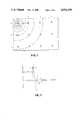
- FIG. 1schematically depicts an array of blast holes in a blasting system according to the invention
- FIG. 2is a graphic representation of a shock wave travelling through a rock body
- FIG. 3is a representation, similar to that contained in FIG. 2, of a complex shock wave pattern generated by multiple blasts,
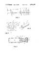
- FIG. 4schematically depicts a detonator firing element for use in the blast system of the invention
- FIG. 5illustrates a sensor for use in the detonator firing element of FIG. 4,
- FIG. 6illustrates one possible form of physical construction of a detonator which incoporates the sensor shown in FIG. 5, and
- FIGS. 7 to 9respectively depict flow charts of different blast control systems.
- FIG. 1illustrates a blast hole pattern in a rock quarry.
- the blast holesare arranged in a rectangular pattern with rows being numbered alphabetically and columns being numbered numerically.
- Shock wavesradiate outwardly from the blast hole and travel through the rock body.
- FIG. 2A typical shock wave pattern is illustrated in FIG. 2.
- the shock wavehas a very sharp leading edge and exhibits oscillatory behaviour with a dampened amplitude.
- the leading edge of the shock wavereaches the hole A2 at a time t which is dependent on the distance d.
- Sound in rocktravels at a speed of from 3000 to 6000 meters per second and consequently for a hole spacing d of the order of one meter the time t is from 166 to 330 microseconds.
- the rise time of the leading edge of the shock waveis of the order of 10 nanoseconds while the width of the pulse is of the order of 1 microsecond.
- Tis very much less than t and it will be readily understood that despite the time lag in detecting the leading edge of the shock wave and the time lag in triggering a detonation at the hole A2 there is nonetheless sufficient time for an explosive to be initiated at the hole A2 so that its resulting shock wave reinforces the shock wave arriving from the hole A1.
- Blasts following the blast in the hole A1also set up shock waves which travel through the body of rock. Clearly a stage is reached at which the shock waves superimposed on one another form a highly complex pattern. Nonetheless it is generally possible to distinguish peaks within the complex pattern which can be used for the synchronisation of subsequent blasts.
- FIG. 3illustrates, on the left hand side, a shock wave pattern which is similar to that shown in FIG. 2 where the time delay T, before a blast is initiated following on detection of the shock wave, is large compared to t.
- FIG. 3shows a complex shock wave pattern which originates within the rock body when a number of successive shock waves are superimposed on one another. A distinct series of peaks remains visible despite the complexity of the signal between the peak values.
- FIG. 4illustrates a detonator firing element 10 which may be of the kind described in the specification of South African Pat. No. 87/3453 and which consequently is not described in detail herein.
- the detonator firing elementincludes a large scale integrated circuit or a very large scale integrated circuit which provides on board signal processing capabilities and inherent safety functions.
- the detonator firing elementis connected to control and power supply lines 12 in a manner which enables bi-directional communications to be established between the detonator firing element and a control computer, not shown.
- a sensor 14is connected to control terminals of the detonator firing element 10.
- the sensor 14may be of any suitable type but preferably is of an accoustic type and, more particalarly, is formed from a piezoelectric polymer such as PDVF.
- FIG. 5depicts a tubular body 16, the inner and outer sufaces of which are metallicly coated to provide electrodes to which are attached leads 18 which facilitate the connection of the sensor 14 to the integrated circuit.
- a fusible link 17is formed integrally with the integrated circuit and explosives material 19 is deposited over the link 17. It is to be understood though that, as is shown in FIG. 6, the link 17 could be a discrete component, which is displaced from the integrated circuit, and which has the explosives material 19 adhering to it.
- the sensor 14when exposed to pressure variations of the type produced by a blast shock wave produces an electrical signal across the leads 18 of the kind shown in FIGS. 2 and 3.
- the electrical circuit of the detonator firing elementis able to monitor the signal and detect the type of sharp leading edge shown in FIGS. 2 and 3.
- the number of shock wave peakscan thus be counted and the count can be used to control the firing of the blasts. It can in general be said that the integrated circuit monitors the rate of rise of the leading edge and also the amplitude of the leading edge and when pre-determined criteria are met generates an output signal to indicate that a pre-determined set of conditions has been met which correspond to the detection of a shock wave.
- the circuit shown in FIG. 4includes a capacitor 20.
- the capacitor 20may be mounted within the tubular body 16 shown in FIG. 5 and the detonator firing element 10 may also be located within the tubular bore of the body.
- FIG. 6illustrates a detonator can 22 which contains conventional explosives material 24.
- the tubular body 16is located in an open end of the can which is then crimped as is shown by a deformation 26 thereby to secure the components to One another in a satisfactory manner and to seal the detonator can.
- the principles of the inventionmay be used in a number of ways.
- a shock wave originating from a pre-determined blast holeAccording to pre-determined criteria a subsequent blast is initiated in order to interfere, either constructively or destructively, with the primary shock wave.
- the primary shock wavemay be maximised or secondary vibratory effects may be minimised.
- delaysmay be in the order of up to 1000 microseconds.
- the blast at each subsequent holewill in general terms depend on detecting the primary shock wave.
- This approachavoids the problem of discriminating a required shock wave from what may be a cluttered shock wave pattern arising inter alia from spurious reflections and superimposed shock waves produced by multiple delayed blasting procedures.
- the first or primary shock wavescalibrate the system, taking into account the actual geometry and the physical parameters of the system and all subsequent blasts are synchronized to the first shock wave and occur substantially immediately or a controlled time delay later.
- the detected shock waveis used to increment a shock counter which is not shown as a separate component but which is programmable and which is carried onboard the integrated circuit in the detonator firing element 10.
- a shock counterwhich is not shown as a separate component but which is programmable and which is carried onboard the integrated circuit in the detonator firing element 10.
- FIG. 2depicts the situation in which a primary shock wave is used to cause initiation of explosives at each of a plurality of blast holes, with a blast at each hole taking place a relatively short time T after detection of the leading edge of the shock wave.
- the time Tis large compared to the time t. In other words there is a significant time delay, calculated to achieve a desired effect, before a subsequent blast is initiated.
- FIG. 3Also shown in FIG. 3 is a technique wherein a plurality of peaks are detected before a blast is initiated. In this case the time delay T is generally speaking substantial compared to the situation occurring with FIG. 2.
- Complex control featuresare incorporated on the integrated circuit of the detonator firing element to prevent an element from firing without first being tested, loaded with a delay, and armed.
- the control system implementedmay be of any suitable type and may for example be based on the use of bi-directional communication techniques as described in the specification of South African Pat. No. 87/3453.
- the information produced by each shock sensoris transmitted along the lines to a control computer 27, see FIG. 4, which calculates delay period criteria according to predetermined formulas and which transmits information on the delay periods to the respective detonators.
- the detonator firing elementis, in addition, only responsive to a signal detected by the sensor 14 once the appropriate circuitry has been enabled.
- the detonator firing elementcan be used to initiate an explosive only once fully armed and primed but, on the other hand, the detonator firing element is de-sensitized and safe to transport and handle when not activated.
- a primary advantage of the inventionis that it enables a blasting procedure to be implemented which can be tailor-made, in real terms, to prevailing physical conditions in order to meet desired objectives. This removes the need to produce a mathematical model of the rock body in order to implement a predictive approach. It is also possible however to implement a system which really is a combination of the predictive and the real time approaches. Thus it falls within the scope of the invention to provide a blasting system which makes use of the various components described thus far. Initially the various detonator firing elements are not activated but are nonetheless capable of recording information detected by the sensors 14 and of transmitting this information to a central collecting point controlled by means of a computer.
- the information coming in on the control lines 12can be collected and analysed in order to arrive very quickly at a model of the rock body which is based on actual measurements.
- the various detonator firing elementscan be pre-programmed from the central computer to fire in a particular manner.
- the on-board sensorsare used mainly in an information collecting role and a blasting procedure is then determined through the use of the central computer which programmes the detonator firing elements accordingly.
- the process described thus farmakes it possible to implement a blast control procedure wherein rocks may be fragmented to a controlled degree.
- This approachwill not necessarily displace the rock fragments from a rock face and, to achieve this, the invention provides a secondary phase wherein use is made of secondary strategically located explosives which are designed to displace the rock from the rock face in order to facilitate the collection of the rock.
- sequenced explosivesare initiated relatively slowly, compared to the first phase, so that reliance is placed more on gas pressure effects to achieve rock displacement, rather than on percussive effects.
- FIGS. 7 to 9respectively depict three flow charts of different sequences of operations in detonation processes.
- a central control computerthe signal processing capability on each detonator firing element, or a combination thereof.
- the development of the softwarelies within the scope of those persons who are skilled in the art and the precise nature of the software is consequently not detailed herein.
- the control instructionsmay be implemented purely by software means, or by hardware means, or by a combination thereof.
- the signal processing capability of such circuitsmay be substantial and logical steps, subject only to the input of critical parameters from an external source, for example from an external control computer, may be implemented directly through hardware i.e. by appropriate design of the circuit itself.
- FIG. 7illustrates a basic application of the principles of the invention.
- Each detonatorwhich comprises for example a device of the kind shown in FIG. 6, i.e. a detonator firing element (FIG. 4) mounted in a can together with explosive, is tested, loaded with a delay, and armed under the control of a blast programmer. The detonator then enters a state during which it draws power from an internal power source such as the capacitor 20.
- an internal power sourcesuch as the capacitor 20.
- the detonatorWhile the detonator is internally powered it waits for the shock wave from the first blast and once this is detected progresses through the loaded time delay before directing current from the internal power source to the ⁇ hot-spot ⁇ i.e. the fusible link 17 (in this example).
- the flow chart of FIG. 8is in respect of a more complex situation.
- the detonatoris intended to detect N peaks of shock waves before commencing the countdown to fire.
- Each detonator firing element(FIG. 4) carries in its integrated circuit an algorithm which indicates a method in which a number N is loaded into the detonator prior to arming. This number N is the number of peak shock waves which are to be detected prior to the initiation of countdown.
- the delays and the number Nare loaded into the detonators.
- the shock counteris initialized so that it is responsive to peak shock waves. After N shock waves have been detected the countdown is commenced.
- the flow chart of FIG. 9depicts a blast system in which a test blast is used to generate information which is detected by a plurality of detonators, as has been described hereinbefore.
- the information from the various detonatorsis returned to a central or blast computer and individual time delays for the respective detonators are calculated by the blast computer. This information is returned to the detonators in readiness for a subsequent arm and countdown message.
- the system depicted in FIG. 9can be implemented on a real-time basis or with a relatively long time-delay between the initial test blast and the subsequent firing of the various detonators.
- the left-hand side of the flow chart of FIG. 9depicts the steps at the blast computer.
- the blast computeris used firstly to initialize, test and calibrate the detonators which are arranged in a predetermined blast pattern.
- timers on the integrated circuits of the detonatorsare commenced and, from each detonator, an indication of the time taken for the shock wave to propagate through the rock to the detonator is obtained.
- the central computerutilises the information together with other data relating to the rock body and, in order to achieve a desired blast pattern, calculates the respective delay times for each detonator. The delay times are then transmitted to the respective detonators and, at an appropriate time, the detonators are armed and then sent countdown instructions.
- the detonatorsare thus used to measure the time delay of a shock wave propagating through the rock body.
- the informationis sent to the central computer for analysis and the ideal delays are then calculated by the computer. Once the delays have been loaded into the detonators they can fired as required.
Landscapes
- Engineering & Computer Science (AREA)
- General Engineering & Computer Science (AREA)
- Drilling And Exploitation, And Mining Machines And Methods (AREA)
Abstract
Description
Claims (5)
Applications Claiming Priority (2)
| Application Number | Priority Date | Filing Date | Title |
|---|---|---|---|
| ZA88/6500 | 1988-09-01 | ||
| ZA886500 | 1988-09-01 |
Publications (1)
| Publication Number | Publication Date |
|---|---|
| US4976199Atrue US4976199A (en) | 1990-12-11 |
Family
ID=25579398
Family Applications (1)
| Application Number | Title | Priority Date | Filing Date |
|---|---|---|---|
| US07/398,890Expired - LifetimeUS4976199A (en) | 1988-09-01 | 1989-08-28 | Blasting system and its method of control |
Country Status (3)
| Country | Link |
|---|---|
| US (1) | US4976199A (en) |
| AU (1) | AU614870B2 (en) |
| CA (1) | CA1339279C (en) |
Cited By (28)
| Publication number | Priority date | Publication date | Assignee | Title |
|---|---|---|---|---|
| US5189246A (en)* | 1989-09-28 | 1993-02-23 | Csir | Timing apparatus |
| US5375527A (en)* | 1992-02-25 | 1994-12-27 | Nakajima; Yasuji | Method for blasting employing bar-like charge |
| US5388521A (en)* | 1993-10-18 | 1995-02-14 | Coursen Family Trust | Method of reducing ground vibration from delay blasting |
| FR2725782A1 (en)* | 1994-10-12 | 1996-04-19 | Bernard Thierry | Planned firing of explosive charges |
| US6422147B1 (en)* | 1998-07-07 | 2002-07-23 | Hatorex Ag A Swiss Limited Liability Company | Sequential detonation of explosive charges |
| WO2003083406A1 (en)* | 2002-03-28 | 2003-10-09 | Orica Explosives Technology Pty Ltd | System and method for monitoring features of a blast |
| US6772105B1 (en) | 1999-09-08 | 2004-08-03 | Live Oak Ministries | Blasting method |
| US20040159258A1 (en)* | 2001-01-19 | 2004-08-19 | Brent Geoffrey Frederick | Method of blasting |
| US20050015473A1 (en)* | 2003-07-15 | 2005-01-20 | Special Devices, Inc. | Dynamically-and continuously-variable rate, asynchronous data transfer |
| US20050103219A1 (en)* | 2003-11-04 | 2005-05-19 | Advanced Initiation Systems, Inc. | Positional blasting system |
| WO2006086843A1 (en)* | 2005-02-16 | 2006-08-24 | Orica Explosives Technology Pty Ltd | Blasting methods and apparatus with reduced risk of inadvertent or illicit use |
| KR100665878B1 (en) | 2005-10-27 | 2007-01-09 | 에스케이건설 주식회사 | Low Vibration Low Noise Blasting Pattern Design Method |
| US20070095237A1 (en)* | 1999-12-07 | 2007-05-03 | Dyno Nobel Sweden Ab | Method for providing a delay time |
| CN100395509C (en)* | 2004-12-08 | 2008-06-18 | 广东宏大爆破股份有限公司 | Electric calculating precise time delay interference shock eliminating blasting method |
| US20100225155A1 (en)* | 2007-05-25 | 2010-09-09 | Alexander Theofile Spathis | Use of post-blast markers in the mining of mineral deposits |
| US7804741B1 (en)* | 2009-09-28 | 2010-09-28 | The United States Of America As Represented By The Secretary Of The Navy | System and method for focusing a kinetic pulse array |
| CN102095338A (en)* | 2010-12-14 | 2011-06-15 | 中国建筑第八工程局有限公司 | Tunneling electron detonator blasting construction method |
| WO2011115723A1 (en)* | 2010-03-19 | 2011-09-22 | Exxonmobil Upstream Research Company | System and method for fracturing rock in tight reservoirs |
| US8082844B1 (en)* | 2009-05-28 | 2011-12-27 | Raytheon Company | Acoustic crystal explosives |
| US8555768B1 (en) | 2009-05-28 | 2013-10-15 | Raytheon Company | Shock wave barrier using multidimensional periodic structures |
| CN102147219B (en)* | 2010-02-09 | 2013-10-30 | 北京北方邦杰科技发展有限公司 | Electronic detonator supervision system and detonating authorization monitoring management method of electronic detonator supervision system |
| CN103398637A (en)* | 2013-07-29 | 2013-11-20 | 中铁二局股份有限公司 | Mean-peak micro-quake fine control blasting construction method using high-precision digital electronic detonators |
| WO2015123747A1 (en)* | 2014-02-21 | 2015-08-27 | Vale S.A. | Rock blasting method and system for adjusting a blasting plan in real time |
| RU2574425C2 (en)* | 2010-03-19 | 2016-02-10 | Эксонмобил Апстрим Рисерч Компани | System and method for rock fracturing in dense rock strata |
| CN113216845A (en)* | 2021-03-30 | 2021-08-06 | 长江武汉航道工程局 | Prediction method and system for underwater drilling plosive |
| CN113670145A (en)* | 2021-08-24 | 2021-11-19 | 北京理工大学 | A test device and method for testing the ability of an electronic detonator to withstand shock waves |
| CN115406321A (en)* | 2022-09-26 | 2022-11-29 | 三峡大学 | Electronic detonator anti-explosion identification method based on air shock waves |
| US20230194230A1 (en)* | 2020-04-29 | 2023-06-22 | Detnet South Africa (Pty) Ltd | A safety arrangement for a wireless blasting system |
Families Citing this family (3)
| Publication number | Priority date | Publication date | Assignee | Title |
|---|---|---|---|---|
| CN110887419B (en)* | 2019-12-18 | 2022-10-14 | 神华准格尔能源有限责任公司 | Method, storage medium and system for monitoring influence of blasting vibration on step-shaped slope |
| CN117053639B (en)* | 2023-08-15 | 2024-01-30 | 广东中人集团建设有限公司 | Bridge blasting parameter regulation and control method based on real-time monitoring data |
| CN117250109B (en)* | 2023-09-21 | 2024-08-02 | 中山大学 | Energy-gathering device, system and method for underwater explosion soil layer damage test |
Citations (20)
| Publication number | Priority date | Publication date | Assignee | Title |
|---|---|---|---|---|
| US2708877A (en)* | 1948-06-23 | 1955-05-24 | Smitsvonk Nv | Low tension igniter for explosives |
| US2881703A (en)* | 1952-10-06 | 1959-04-14 | Jean Rochat | Spark generating device |
| US3018732A (en)* | 1954-09-30 | 1962-01-30 | Bendix Corp | Ignition means for ammunition primer or the like |
| US3019732A (en)* | 1957-10-29 | 1962-02-06 | Brevets Aero Mecaniques | Electrical primers |
| US3196041A (en)* | 1960-11-25 | 1965-07-20 | Gen Lab Associates Inc | Method of making a semiconductor gap for an initiator |
| US3211096A (en)* | 1962-05-03 | 1965-10-12 | Texaco Experiment Inc | Initiator with a p-n peltier thermoelectric effect junction |
| US3292537A (en)* | 1965-06-15 | 1966-12-20 | Jr Frank A Goss | Multi-signal explosive detonator |
| US3361064A (en)* | 1950-09-07 | 1968-01-02 | Atomic Energy Commission Usa | Electric detonating apparatus |
| FR2075028A5 (en)* | 1970-01-21 | 1971-10-08 | Olin Corp | Explosive detonator |
| US3659527A (en)* | 1970-10-29 | 1972-05-02 | Atomic Energy Commission | High temperature detonator |
| US4037538A (en)* | 1973-10-31 | 1977-07-26 | Imperial Chemical Industries Limited | Device for firing an electric detonator |
| US4037537A (en)* | 1974-10-04 | 1977-07-26 | Linden-Alimak Ab | Method and a device for blasting |
| DE2747163A1 (en)* | 1977-10-20 | 1979-04-26 | Dynamit Nobel Ag | ELECTRICAL ELEMENT |
| US4313380A (en)* | 1978-09-15 | 1982-02-02 | Standard Oil Company (Indiana) | Distributed charge for seismic prospecting |
| GB2123122A (en)* | 1982-01-08 | 1984-01-25 | Hunting Eng Ltd | Explosive devices |
| US4484523A (en)* | 1983-03-28 | 1984-11-27 | The United States Of America As Represented By The Secretary Of The Navy | Detonator, solid state type I film bridge |
| DE3322990A1 (en)* | 1983-06-25 | 1985-01-10 | Siemens AG, 1000 Berlin und 8000 München | Circuit arrangement for triggering an explosive charge and fuse which can be used for this |
| DE3537820A1 (en)* | 1985-10-24 | 1987-04-30 | Dynamit Nobel Ag | Electronic fuze |
| US4699241A (en)* | 1985-10-24 | 1987-10-13 | Atlantic Richfield Company | Method and apparatus for detonation of distributed charges |
| US4819560A (en)* | 1986-05-22 | 1989-04-11 | Detonix Close Corporation | Detonator firing element |
- 1989
- 1989-08-24AUAU40248/89Apatent/AU614870B2/ennot_activeExpired
- 1989-08-25CACA000609444Apatent/CA1339279C/ennot_activeExpired - Lifetime
- 1989-08-28USUS07/398,890patent/US4976199A/ennot_activeExpired - Lifetime
Patent Citations (20)
| Publication number | Priority date | Publication date | Assignee | Title |
|---|---|---|---|---|
| US2708877A (en)* | 1948-06-23 | 1955-05-24 | Smitsvonk Nv | Low tension igniter for explosives |
| US3361064A (en)* | 1950-09-07 | 1968-01-02 | Atomic Energy Commission Usa | Electric detonating apparatus |
| US2881703A (en)* | 1952-10-06 | 1959-04-14 | Jean Rochat | Spark generating device |
| US3018732A (en)* | 1954-09-30 | 1962-01-30 | Bendix Corp | Ignition means for ammunition primer or the like |
| US3019732A (en)* | 1957-10-29 | 1962-02-06 | Brevets Aero Mecaniques | Electrical primers |
| US3196041A (en)* | 1960-11-25 | 1965-07-20 | Gen Lab Associates Inc | Method of making a semiconductor gap for an initiator |
| US3211096A (en)* | 1962-05-03 | 1965-10-12 | Texaco Experiment Inc | Initiator with a p-n peltier thermoelectric effect junction |
| US3292537A (en)* | 1965-06-15 | 1966-12-20 | Jr Frank A Goss | Multi-signal explosive detonator |
| FR2075028A5 (en)* | 1970-01-21 | 1971-10-08 | Olin Corp | Explosive detonator |
| US3659527A (en)* | 1970-10-29 | 1972-05-02 | Atomic Energy Commission | High temperature detonator |
| US4037538A (en)* | 1973-10-31 | 1977-07-26 | Imperial Chemical Industries Limited | Device for firing an electric detonator |
| US4037537A (en)* | 1974-10-04 | 1977-07-26 | Linden-Alimak Ab | Method and a device for blasting |
| DE2747163A1 (en)* | 1977-10-20 | 1979-04-26 | Dynamit Nobel Ag | ELECTRICAL ELEMENT |
| US4313380A (en)* | 1978-09-15 | 1982-02-02 | Standard Oil Company (Indiana) | Distributed charge for seismic prospecting |
| GB2123122A (en)* | 1982-01-08 | 1984-01-25 | Hunting Eng Ltd | Explosive devices |
| US4484523A (en)* | 1983-03-28 | 1984-11-27 | The United States Of America As Represented By The Secretary Of The Navy | Detonator, solid state type I film bridge |
| DE3322990A1 (en)* | 1983-06-25 | 1985-01-10 | Siemens AG, 1000 Berlin und 8000 München | Circuit arrangement for triggering an explosive charge and fuse which can be used for this |
| DE3537820A1 (en)* | 1985-10-24 | 1987-04-30 | Dynamit Nobel Ag | Electronic fuze |
| US4699241A (en)* | 1985-10-24 | 1987-10-13 | Atlantic Richfield Company | Method and apparatus for detonation of distributed charges |
| US4819560A (en)* | 1986-05-22 | 1989-04-11 | Detonix Close Corporation | Detonator firing element |
Cited By (65)
| Publication number | Priority date | Publication date | Assignee | Title |
|---|---|---|---|---|
| US5189246A (en)* | 1989-09-28 | 1993-02-23 | Csir | Timing apparatus |
| US5282421A (en)* | 1989-09-28 | 1994-02-01 | Csir | Timing apparatus |
| AU657217B2 (en)* | 1989-09-28 | 1995-03-02 | Csir | Timing apparatus |
| US5406890A (en)* | 1989-09-28 | 1995-04-18 | Csir | Timing apparatus |
| US5375527A (en)* | 1992-02-25 | 1994-12-27 | Nakajima; Yasuji | Method for blasting employing bar-like charge |
| US5388521A (en)* | 1993-10-18 | 1995-02-14 | Coursen Family Trust | Method of reducing ground vibration from delay blasting |
| FR2725782A1 (en)* | 1994-10-12 | 1996-04-19 | Bernard Thierry | Planned firing of explosive charges |
| US6422147B1 (en)* | 1998-07-07 | 2002-07-23 | Hatorex Ag A Swiss Limited Liability Company | Sequential detonation of explosive charges |
| US8538698B2 (en) | 1999-09-08 | 2013-09-17 | Live Oak Ministries | Blasting method |
| US7418373B2 (en) | 1999-09-08 | 2008-08-26 | Live Oak Ministries | Blasting method |
| US20050010385A1 (en)* | 1999-09-08 | 2005-01-13 | Heck Jay Howard | Blasting method |
| US6772105B1 (en) | 1999-09-08 | 2004-08-03 | Live Oak Ministries | Blasting method |
| US8380436B2 (en) | 1999-09-08 | 2013-02-19 | Live Oak Ministries | Blasting method |
| US20070095237A1 (en)* | 1999-12-07 | 2007-05-03 | Dyno Nobel Sweden Ab | Method for providing a delay time |
| US20040159258A1 (en)* | 2001-01-19 | 2004-08-19 | Brent Geoffrey Frederick | Method of blasting |
| US7406918B2 (en) | 2001-01-19 | 2008-08-05 | Orica Explosives Technology Pty Ltd. | Method of blasting |
| US7370513B2 (en) | 2002-03-28 | 2008-05-13 | Orica Explosives Technology Pty. Ltd. | System and method for monitoring features of a blast |
| US20050247109A1 (en)* | 2002-03-28 | 2005-11-10 | Meyer Eric N | System and method for monitoring features of a blast |
| WO2003083406A1 (en)* | 2002-03-28 | 2003-10-09 | Orica Explosives Technology Pty Ltd | System and method for monitoring features of a blast |
| US20050015473A1 (en)* | 2003-07-15 | 2005-01-20 | Special Devices, Inc. | Dynamically-and continuously-variable rate, asynchronous data transfer |
| US7577756B2 (en) | 2003-07-15 | 2009-08-18 | Special Devices, Inc. | Dynamically-and continuously-variable rate, asynchronous data transfer |
| US8176848B2 (en) | 2003-07-15 | 2012-05-15 | Austin Star Detonator Company | Electronic blasting system having a pre-fire countdown with multiple fire commands |
| US7971531B2 (en) | 2003-07-15 | 2011-07-05 | Austin Star Detonator Company | Method for detecting an unknown or unmarked slave device such as in an electronic blasting system |
| US7650841B2 (en) | 2003-11-04 | 2010-01-26 | Davey Bickford Usa, Inc. | Positional blasting system |
| US20050217525A1 (en)* | 2003-11-04 | 2005-10-06 | Advanced Initiation Systems, Inc. | Positional blasting system |
| US20050103219A1 (en)* | 2003-11-04 | 2005-05-19 | Advanced Initiation Systems, Inc. | Positional blasting system |
| US6941870B2 (en) | 2003-11-04 | 2005-09-13 | Advanced Initiation Systems, Inc. | Positional blasting system |
| CN100395509C (en)* | 2004-12-08 | 2008-06-18 | 广东宏大爆破股份有限公司 | Electric calculating precise time delay interference shock eliminating blasting method |
| US20060262480A1 (en)* | 2005-02-16 | 2006-11-23 | Stewart Ronald F | Security enhanced blasting apparatus, and method of blasting |
| US9091519B2 (en) | 2005-02-16 | 2015-07-28 | Orica Explosives Technology Pty Ltd | Apparatus and method for blasting |
| WO2006086843A1 (en)* | 2005-02-16 | 2006-08-24 | Orica Explosives Technology Pty Ltd | Blasting methods and apparatus with reduced risk of inadvertent or illicit use |
| US20110067591A1 (en)* | 2005-02-16 | 2011-03-24 | Orica Explosives Technology Pty Ltd | Security enhanced blasting apparatus, and method of blasting |
| US8839720B2 (en) | 2005-02-16 | 2014-09-23 | Orica Explosives Technology Pty Ltd | Security enhanced blasting apparatus, and method of blasting |
| US9091518B2 (en) | 2005-02-16 | 2015-07-28 | Orica Explosives Technology Pty Ltd | Apparatus and method for blasting |
| US7958824B2 (en) | 2005-02-16 | 2011-06-14 | Orica Explosives Technology Pty Ltd. | Security enhanced blasting apparatus, and method of blasting |
| US20060272536A1 (en)* | 2005-02-16 | 2006-12-07 | Lownds Charles M | Apparatus and method for blasting |
| KR100665878B1 (en) | 2005-10-27 | 2007-01-09 | 에스케이건설 주식회사 | Low Vibration Low Noise Blasting Pattern Design Method |
| US8955916B2 (en) | 2007-05-25 | 2015-02-17 | Orica Explosive Technology Pty Ltd | Use of post-blast markers in the mining of mineral deposits |
| US20100225155A1 (en)* | 2007-05-25 | 2010-09-09 | Alexander Theofile Spathis | Use of post-blast markers in the mining of mineral deposits |
| US8398175B2 (en)* | 2007-05-25 | 2013-03-19 | Orica Explosives Technology Pty Ltd | Use of post-blast markers in the mining of mineral deposits |
| US8082844B1 (en)* | 2009-05-28 | 2011-12-27 | Raytheon Company | Acoustic crystal explosives |
| US8555768B1 (en) | 2009-05-28 | 2013-10-15 | Raytheon Company | Shock wave barrier using multidimensional periodic structures |
| US20110075513A1 (en)* | 2009-09-28 | 2011-03-31 | Trevor Snow | Locator system and method including node and target acquisition |
| US8154954B1 (en) | 2009-09-28 | 2012-04-10 | The United States Of America As Represented By The Secretary Of The Navy | Projectile for focusing a kinetic pulse array |
| US7804741B1 (en)* | 2009-09-28 | 2010-09-28 | The United States Of America As Represented By The Secretary Of The Navy | System and method for focusing a kinetic pulse array |
| US7948829B2 (en) | 2009-09-28 | 2011-05-24 | The United States Of America As Represented By The Secretary Of The Navy | Locator system and method including node and target acquisition |
| US7813223B1 (en)* | 2009-09-28 | 2010-10-12 | The United States Of America As Represented By The Secretary Of The Navy | System and method for focusing a kinetic pulse array |
| CN102147219B (en)* | 2010-02-09 | 2013-10-30 | 北京北方邦杰科技发展有限公司 | Electronic detonator supervision system and detonating authorization monitoring management method of electronic detonator supervision system |
| US9057261B2 (en) | 2010-03-19 | 2015-06-16 | Exxonmobil Upstream Research Company | System and method for fracturing rock in tight reservoirs |
| RU2574425C2 (en)* | 2010-03-19 | 2016-02-10 | Эксонмобил Апстрим Рисерч Компани | System and method for rock fracturing in dense rock strata |
| CN102803650A (en)* | 2010-03-19 | 2012-11-28 | 埃克森美孚上游研究公司 | System and method for fracturing rock in tight reservoirs |
| WO2011115723A1 (en)* | 2010-03-19 | 2011-09-22 | Exxonmobil Upstream Research Company | System and method for fracturing rock in tight reservoirs |
| CN102803650B (en)* | 2010-03-19 | 2015-11-25 | 埃克森美孚上游研究公司 | The system and method for rock in fracturing tight reservoir |
| CN102095338A (en)* | 2010-12-14 | 2011-06-15 | 中国建筑第八工程局有限公司 | Tunneling electron detonator blasting construction method |
| CN103398637B (en)* | 2013-07-29 | 2015-07-15 | 中铁二局股份有限公司 | Mean-peak micro-quake fine control blasting construction method using high-precision digital electronic detonators |
| CN103398637A (en)* | 2013-07-29 | 2013-11-20 | 中铁二局股份有限公司 | Mean-peak micro-quake fine control blasting construction method using high-precision digital electronic detonators |
| AU2015221430B2 (en)* | 2014-02-21 | 2019-03-14 | Associação Instituto Tecnológico Vale – Itv | Rock blasting method and system for adjusting a blasting plan in real time |
| WO2015123747A1 (en)* | 2014-02-21 | 2015-08-27 | Vale S.A. | Rock blasting method and system for adjusting a blasting plan in real time |
| US20230194230A1 (en)* | 2020-04-29 | 2023-06-22 | Detnet South Africa (Pty) Ltd | A safety arrangement for a wireless blasting system |
| US12174003B2 (en)* | 2020-04-29 | 2024-12-24 | Detnet South Africa (Pty) Ltd | Safety arrangement for a wireless blasting system |
| CN113216845A (en)* | 2021-03-30 | 2021-08-06 | 长江武汉航道工程局 | Prediction method and system for underwater drilling plosive |
| CN113216845B (en)* | 2021-03-30 | 2024-03-29 | 长江武汉航道工程局 | Prediction method and system for underwater drilling plosives |
| CN113670145A (en)* | 2021-08-24 | 2021-11-19 | 北京理工大学 | A test device and method for testing the ability of an electronic detonator to withstand shock waves |
| CN113670145B (en)* | 2021-08-24 | 2023-08-29 | 北京理工大学 | A test device and method for testing the ability of electronic detonators to withstand shock waves |
| CN115406321A (en)* | 2022-09-26 | 2022-11-29 | 三峡大学 | Electronic detonator anti-explosion identification method based on air shock waves |
Also Published As
| Publication number | Publication date |
|---|---|
| CA1339279C (en) | 1997-08-12 |
| AU614870B2 (en) | 1991-09-12 |
| AU4024889A (en) | 1990-03-08 |
Similar Documents
| Publication | Publication Date | Title |
|---|---|---|
| US4976199A (en) | Blasting system and its method of control | |
| US5388521A (en) | Method of reducing ground vibration from delay blasting | |
| US5460093A (en) | Programmable electronic time delay initiator | |
| EP2593747B1 (en) | Timing module | |
| CA2306536C (en) | Blasting process | |
| US4699241A (en) | Method and apparatus for detonation of distributed charges | |
| US10890426B2 (en) | Detonator | |
| US3851589A (en) | Electronic delay blaster | |
| EP1009967A1 (en) | Sequential detonation of explosive charges | |
| US7370513B2 (en) | System and method for monitoring features of a blast | |
| GB2057733A (en) | Transmitting information to explosive etc. devices | |
| WO1990012332A1 (en) | Improved method and apparatus for detonation of distributed charges | |
| US4135452A (en) | Time delay computer using fuze doppler for air-to-air missiles | |
| US3741124A (en) | Demolition firing device | |
| RU2237847C2 (en) | Device for protection of test objects against hitting elements having abnormal speed | |
| GB1525826A (en) | Hand grenades | |
| US5617097A (en) | Low-cost near-surface burst (NSB) capability for proximity fuzes | |
| ZA200701067B (en) | Detonator | |
| WO1993018366A1 (en) | Arrangement for effecting detonation of explosive materials | |
| CN112444168B (en) | Accurate timer for preventing wiring error electric shock and tube explosion | |
| AU2015201933B2 (en) | Timing module | |
| Mui et al. | The use of electronic detonators in vibration control for blasting | |
| AU2017100266A4 (en) | Detonator | |
| Brumleve et al. | System for remote control of underground device | |
| JP2001289600A (en) | Large blast suppression blasting method and delayed firing second time interval determination method |
Legal Events
| Date | Code | Title | Description |
|---|---|---|---|
| AS | Assignment | Owner name:EXPERT EXPLOSIVES (PROPRIETARY) LIMITED, SOUTH AFR Free format text:ASSIGNMENT OF ASSIGNORS INTEREST.;ASSIGNORS:BEUKES, CHRISTO A.;PATZ, VIVIAN E.;MORAITIS, THRASYVOULAS;REEL/FRAME:005117/0797 Effective date:19890816 | |
| STCF | Information on status: patent grant | Free format text:PATENTED CASE | |
| FEPP | Fee payment procedure | Free format text:PAYOR NUMBER ASSIGNED (ORIGINAL EVENT CODE: ASPN); ENTITY STATUS OF PATENT OWNER: LARGE ENTITY | |
| FPAY | Fee payment | Year of fee payment:4 | |
| FPAY | Fee payment | Year of fee payment:8 | |
| AS | Assignment | Owner name:IMPERIAL CHEMICAL INDUSTRIES PLC, ENGLAND Free format text:ASSIGNMENT OF ASSIGNORS INTEREST;ASSIGNOR:EXPERT EXPLOSIVES (PTY) LTD;REEL/FRAME:010461/0424 Effective date:19980422 Owner name:ORICA EXPLOSIVES TECHNOLOGY PTY LTD, AUSTRALIA Free format text:ASSIGNMENT OF ASSIGNORS INTEREST;ASSIGNOR:IMPERICAL CHEMICAL INDUSTRIES PLC;REEL/FRAME:010461/0653 Effective date:19990917 | |
| FPAY | Fee payment | Year of fee payment:12 |