US4974646A - Powder flow control valve - Google Patents
Powder flow control valveDownload PDFInfo
- Publication number
- US4974646A US4974646AUS07/274,924US27492488AUS4974646AUS 4974646 AUS4974646 AUS 4974646AUS 27492488 AUS27492488 AUS 27492488AUS 4974646 AUS4974646 AUS 4974646A
- Authority
- US
- United States
- Prior art keywords
- powder
- flow
- nozzle
- valve
- boundary surface
- Prior art date
- Legal status (The legal status is an assumption and is not a legal conclusion. Google has not performed a legal analysis and makes no representation as to the accuracy of the status listed.)
- Expired - Fee Related
Links
- 239000000843powderSubstances0.000titleclaimsabstractdescription80
- 230000005484gravityEffects0.000claimsabstractdescription9
- 238000005192partitionMethods0.000claimsdescription8
- 230000003213activating effectEffects0.000claimsdescription3
- 230000000977initiatory effectEffects0.000claimsdescription2
- 239000000463materialSubstances0.000abstractdescription10
- 229920000573polyethylenePolymers0.000abstract1
- 239000008187granular materialSubstances0.000description6
- 235000013305foodNutrition0.000description4
- 230000001276controlling effectEffects0.000description3
- 239000000919ceramicSubstances0.000description1
- 238000005056compactionMethods0.000description1
- 238000010276constructionMethods0.000description1
- 229920001903high density polyethylenePolymers0.000description1
- 239000004700high-density polyethyleneSubstances0.000description1
- 238000005259measurementMethods0.000description1
- 239000002184metalSubstances0.000description1
- 239000000203mixtureSubstances0.000description1
- 239000004482other powderSubstances0.000description1
- 229920003023plasticPolymers0.000description1
- 239000004033plasticSubstances0.000description1
- 239000011148porous materialSubstances0.000description1
- 230000001105regulatory effectEffects0.000description1
- 238000007789sealingMethods0.000description1
- 235000014347soupsNutrition0.000description1
Images


Classifications
- B—PERFORMING OPERATIONS; TRANSPORTING
- B65—CONVEYING; PACKING; STORING; HANDLING THIN OR FILAMENTARY MATERIAL
- B65B—MACHINES, APPARATUS OR DEVICES FOR, OR METHODS OF, PACKAGING ARTICLES OR MATERIALS; UNPACKING
- B65B1/00—Packaging fluent solid material, e.g. powders, granular or loose fibrous material, loose masses of small articles, in individual containers or receptacles, e.g. bags, sacks, boxes, cartons, cans, or jars
- B65B1/04—Methods of, or means for, filling the material into the containers or receptacles
- B65B1/16—Methods of, or means for, filling the material into the containers or receptacles by pneumatic means, e.g. by suction
- B—PERFORMING OPERATIONS; TRANSPORTING
- B65—CONVEYING; PACKING; STORING; HANDLING THIN OR FILAMENTARY MATERIAL
- B65B—MACHINES, APPARATUS OR DEVICES FOR, OR METHODS OF, PACKAGING ARTICLES OR MATERIALS; UNPACKING
- B65B39/00—Nozzles, funnels or guides for introducing articles or materials into containers or wrappers
- B—PERFORMING OPERATIONS; TRANSPORTING
- B65—CONVEYING; PACKING; STORING; HANDLING THIN OR FILAMENTARY MATERIAL
- B65D—CONTAINERS FOR STORAGE OR TRANSPORT OF ARTICLES OR MATERIALS, e.g. BAGS, BARRELS, BOTTLES, BOXES, CANS, CARTONS, CRATES, DRUMS, JARS, TANKS, HOPPERS, FORWARDING CONTAINERS; ACCESSORIES, CLOSURES, OR FITTINGS THEREFOR; PACKAGING ELEMENTS; PACKAGES
- B65D90/00—Component parts, details or accessories for large containers
- B65D90/54—Gates or closures
- G—PHYSICS
- G01—MEASURING; TESTING
- G01G—WEIGHING
- G01G13/00—Weighing apparatus with automatic feed or discharge for weighing-out batches of material
- G01G13/003—Details; specially adapted accessories
Definitions
- This inventionrelates to a powder flow control valve and to a dispensing apparatus for powders incorporating such control valves.
- the term "powders"is intended to include fine powder material and also coarser material including granular material which is free flowing.
- U.K. Patent Publication No. 2158813Bdiscloses a powder flow control valve in which a powder flow path is surrounded by a perforated boundary surface which converges in the direction of flow along the path. Means are provided for creating a drop in pressure across the boundary surface with the higher pressure on the powder flow path side of the boundary surface to stop flow of the powder along the path and further means are provided for creating pressure rise across the boundary surface with the lower pressure on the powder flow side of the boundary surface to promote the flow of powder along the path.
- the valveprovides a highly responsive way of controlling the flow of powder but in some cases cut off cannot be determine sufficiently accurately to avoid over filling of the container.
- the inventionprovides a powder flow control valve in which a downwardly extending powder flow path is surrounded by a perforated boundary surface converging, parallel and/or diverging in the downward direction of flow along the path and in which means are provided for creating a pressure drop across the boundary surface with the higher pressure on the powder flow path side of the boundary surface to terminate flow of said powder along the path, second means for creating a pressure rise across the boundary surface with the lower pressure on the powder flow both side of the surface to promote flow of powder along the path and control means for said first and second means for activating the second means to promote powder flow through the valve, deactivating the second means and, after a predetermined period during which powder flows under gravity through the valve, activating the first means to terminate flow through the valve.
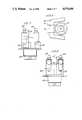
- FIG. 1is a perspective view of a powder dispensing device including a hopper having an outlet valve controlled by a pneumatic system;
- FIG. 2is a front view of the device
- FIG. 3is a side view of the device
- FIG. 4is a plan view of the device
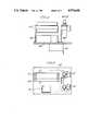
- FIG. 5is a detailed view of the pneumatically operated control valve at the base of the hopper
- FIG. 6is a side view of the pneumatic control system for the valve
- FIG. 7is a rear view of the pneumatic control system
- FIG. 8is a front view of the pneumatic control system
- FIG. 9is a plan view of the pneumatic control system
- FIG. 10is a diagrammatic view of a further form of control valve
- FIG. 11is a diagrammatic view of a further form of control valve
- FIG. 11cshows a modified form of the control valve of FIG. 11.
- FIG. 12is a diagrammatic illustration of a pneumatic control circuit for the device.
- FIGS. 1 to 4 of the drawingsthere is shown a device for filling containers with a predetermined weight of powder material comprising a base 10, an upright pillar 11, a platform 12 mounted part way up the pillar 11 to receive containers one by one to be filled, a hopper 13 mounted at the upper end of the pillar holding a supply of powder to be dispensed by a pneumatically operated control valve 14 for controlling flow of powder from the outlet of the hopper and a pneumatic system 15 for controlling operation of the valve.
- the platform 12is mounted on a cantilever arm 16 extending outwardly from a double acting pneumatic ram 17 mounted within the pillar 11.
- the arm 16is connected directly through the side of the ram piston through an appropriate sealing arrangement to provide vertical adjustment of the arm 16 and thereby the platform 12 under the control of air pressure supplied to opposite ends of the cylinder of the ram.
- the height of the platformcan thereby be adjusted to cater for different size containers to be filled.
- the platform 12incorporates a weighcell assembly indicated at 18 to respond to the quantity of powder deposited in the container on the platform and to control the dispensing of the powder from the hopper as described later.
- FIG. 5 of the drawingsshows the construction of the pneumatically operated control valve in detail.
- the sleevehas a frustoconical bore 22 to receive the lower end part of the hopper 13 which is welded to the sleeve at the upper and lower ends of the sleeve.
- the portion of the sleeve extending below the support plate 19has an external screw thread 23 and an internally threaded collar 24 is screwed onto the sleeve to engage the underside of the support plate 19 and lock the sleeve in position in the plate.
- the downwardly extending generally tubular nozzle holder 25is secured to the lower end of sleeve 21 by means of clamping ring 26 which also screws onto the threaded portion 23 of sleeve 21 and which has an annular shoulder 27 around its inner periphery which engages under an out-turned flange 28 around the upper periphery of nozzle holder 25.
- An "O" ring seal 29is lodged in an annular recess 30 on the underside of the sleeve 21 to seal with the upper end face of the nozzle holder.
- the lower end of the nozzle holderhas an internal flange 31 encircling an outlet aperture 32.
- the nozzle holdercontains a porous nozzle 33 formed from a material such as high density polyethylene or other porous material such as a ceramic or sintered metal or other plastics material.
- the nozzleincludes a wall having an interior or first surface which encircles and defines the powder flow path.
- the nozzlehas an upper frusto conical section 33a which converges towards the lower end of the nozzle and terminates in a plain cylindrical section 33b. The upper end of the nozzle engages around the outlet end of the hopper 13 and the lower end of the nozzle is lodged on the flange 31 encircling the lower end of the nozzle holder to hold the nozzle firmly in place.
- the nozzle holder 25has an upper generally cylindrical part 25a and a lower convergent part 25b to provide a plenum chamber 34 encircling the outer surface of the nozzle 33.
- a port 35is formed in the lower part of the nozzle holder which is connected to a source of vacuum or air pressure through the pneumatic control system 14 which will be described in greater detail below.
- powderis supplied to the hopper 13 and falls into the nozzle 33.
- airis being sucked out of the plenum chamber 34, air is drawn from the passage in the nozzle and this causes powder in the nozzle to adhere to the surface of the nozzle.
- a build up of powderoccurs in the nozzle until the nozzle is effectively blocked closing off flow through the nozzle.
- Flow through the nozzleis established by supplying air under pressure to the plenum chamber 34 and this releases powder from the wall of the nozzle to allow the powder to flow through the outlet 32.
- the air pressureaccelerates the powder through the outlet to create a flow of the powder through the valve from the hopper to fill a container on the platform 12.
- the air pressure supplyis switched off at a point in the filling cycle before the container is full and the powder is allowed to fall under gravity from the hopper to the container to complete the filling operation.
- the proportion of the filling cycle which is carried out with air pressure in relation to the proportion in which the powder falls under gravityis varied to suit the powder being dispensed, the accuracy of fill required and the required cycle time.
- air pressuremay be supplied to the plenum chamber to establish the flow of powder through the valve for a very short duration to establish flow through the valve and once that flow has been established, the air pressure is switched off and the remaining flow is allowed to take place under gravity alone.
- the weighcell on the platform 12monitors the filling operation and is arranged to trigger operation of the vacuum means to the plenum chamber 34 just before the container has been filled to the required extent so that the powder "in flight" between the valve and container will complete the filling operation.
- the pneumatic control system for the valve 14 referred to abovewill now be described briefly in relation to FIGS. 5 to 9 and 12 of the drawings.
- the control systemcomprises a vacuum pump 40, spool valves 41, filter regulators 42 and 43, the control valve 44 for the aforesaid ram 17 and a support plate 45 for the electronic control system.
- the pumpprovides a source of vacuum to the plenum chamber 34 and is controlled through spool valves 41.
- a suitable supply of positive pressure to the plenum chamber 34is provided through and regulated by filter regulators 42 and 43 and controlled by spool valves 41 which lead to a conduit 46 connected to the nozzle 33.
- FIG. 12is one typical layout of a pneumatic control system for the nozzle 33.
- the valvesare controlled through the electronic control system by the weighcell as indicated above.
- the apparatuscan be used for dispensing a variety of powder or granular materials such as "Bournvita”, coffee powder and semolina. It is not however restricted to food products and other powder or granular materials can be dispensed using the apparatus into containers as required.
- the nozzle cone angleis varied according to the nature of the powder or granular material to be dispensed. An angle of 30° is effective for some materials, an angle of 15° for others. If it is found that the powder flow pulsates, a cylindrical lower section at the bottom of the cone as illustrated helps to smooth out the flow. Further variations on the cone/parallel format could include a cone-parallel-cone format or a double cone-parallel configuration.
- the precise design of the porous nozzle utilised in the flow control valvecan be varied considerably to suit the application.
- the angle of the frusto conical part of the nozzlemay be varied according to the nature of the product and the length of the cylindrical part of the nozzle can be varied or the cylindrical part of the nozzle can be omitted altogether.
- FIG. 10shows a further arrangement in which the nozzle has a central dividing partition 50 and in this case the plenum chamber encircling the nozzle is divided into two sections corresponding to the parts of the nozzle on either side of the partition so that flow down either side of the partition can be individually controlled.
- Thisenables initial filling to take place through the whole nozzle and the flow to be halved towards the end of the filling operation by switching off flow through the part of the nozzle to one side of the partition by applying vacuum to the wall of the nozzle around that part leaving flow to continue through the other part of the nozzle to complete the filling operation at a reduced rate.
- a "trickle" of powdercan be supplied to the container at the end of the filling operation and cut off instantaneously to minimise over filling of the container.
- the nozzlecould of course be further sub-divided by further partitions and the plenum chamber correspondingly divided to provide a graduated control of the flow.
- FIG. 11 of the drawingsA further arrangement is illustrated in FIG. 11 of the drawings in which the plenum chamber 34 is divided by a horizontal wall 34a into upper and lower sections corresponding to the frusto conical and cylindrical parts of the porous nozzle to enable the latter to be controlled individually.
- a tubular element 51is disposed concentrically within the cylindrical part 33b of the nozzle mounted on support pins indicated at 52. If air pressure is applied to both upper 34b and lower 34c parts of the plenum chamber 34 or neither part is connected to the vacuum, the powder will flow through the valve and both through the tube and between the tube and cylindrical part of the nozzle.
- a still further arrangement which is not illustratedcould comprise twin nozzles differently sized for bulk fill and topping up arranged side-by-side one another.
- the larger, bulk fill nozzlewould be closed just before the container was full leaving the smaller nozzle to complete the filing operation since there would be less material "in flight" when the smaller nozzle is finally closed, the risk of substantially over filling is minimised.
- the filling apparatus described aboveis suitable for dispensing a wide variety of different forms of powders and granular materials or mixtures of such materials include powder soups containing granules of different foods, mueslies and other such materials.
Landscapes
- Engineering & Computer Science (AREA)
- Mechanical Engineering (AREA)
- Physics & Mathematics (AREA)
- General Physics & Mathematics (AREA)
- Flow Control (AREA)
- Basic Packing Technique (AREA)
- Air Transport Of Granular Materials (AREA)
- Coating Apparatus (AREA)
Abstract
Description
Claims (11)
Applications Claiming Priority (2)
| Application Number | Priority Date | Filing Date | Title |
|---|---|---|---|
| GB878727425AGB8727425D0 (en) | 1987-11-23 | 1987-11-23 | Powder flow control valves |
| GB8727425 | 1987-11-23 |
Publications (1)
| Publication Number | Publication Date |
|---|---|
| US4974646Atrue US4974646A (en) | 1990-12-04 |
Family
ID=10627416
Family Applications (1)
| Application Number | Title | Priority Date | Filing Date |
|---|---|---|---|
| US07/274,924Expired - Fee RelatedUS4974646A (en) | 1987-11-23 | 1988-11-23 | Powder flow control valve |
Country Status (6)
| Country | Link |
|---|---|
| US (1) | US4974646A (en) |
| EP (1) | EP0318247B1 (en) |
| JP (1) | JPH0681986B2 (en) |
| AT (1) | ATE76845T1 (en) |
| DE (1) | DE3871733T2 (en) |
| GB (2) | GB8727425D0 (en) |
Cited By (55)
| Publication number | Priority date | Publication date | Assignee | Title |
|---|---|---|---|---|
| US5339871A (en)* | 1993-05-04 | 1994-08-23 | Philip Morris Incorporated | Apparatus and methods for transferring and metering granular material |
| US5405647A (en)* | 1993-11-02 | 1995-04-11 | Owens-Corning Fiberglass Technology Inc. | Method for applying granules to a moving coated asphalt sheet to form areas having sharp leading and trailing edges |
| US5423356A (en)* | 1993-02-24 | 1995-06-13 | Haver & Boecker | Filling pipe for use in a filling machine for filling in particular valve sacks |
| US5520889A (en)* | 1993-11-02 | 1996-05-28 | Owens-Corning Fiberglas Technology, Inc. | Method for controlling the discharge of granules from a nozzle onto a coated sheet |
| US5598876A (en)* | 1994-03-28 | 1997-02-04 | Azionaria Costruzioni Macchine Automatiche A.C.M.A. S.P.A. | Powdered material dispensing unit |
| US5599581A (en)* | 1993-11-02 | 1997-02-04 | Owens Corning Fiberglas Technology, Inc. | Method for pneumatically controlling discharge of particulate material |
| US5624522A (en)* | 1995-06-07 | 1997-04-29 | Owens-Corning Fiberglas Technology Inc. | Method for applying granules to strip asphaltic roofing material to form variegated shingles |
| US5670751A (en)* | 1993-09-21 | 1997-09-23 | Pfister Gmbh | Bulk material weighing container with pressure feedback |
| US5711353A (en)* | 1995-01-26 | 1998-01-27 | Ricoh Company, Ltd. | Powder filling method and powder filling device |
| US5746830A (en)* | 1993-11-02 | 1998-05-05 | Owens-Corning Fiberglas Technology, Inc. | Pneumatic granule blender for asphalt shingles |
| US5747105A (en) | 1996-04-30 | 1998-05-05 | Owens Corning Fiberglas Technology Inc. | Traversing nozzle for applying granules to an asphalt coated sheet |
| US5988234A (en)* | 1998-04-16 | 1999-11-23 | Xerox Corporation | Apparatus for particulate processing |
| US6050456A (en)* | 1997-11-04 | 2000-04-18 | Progressive Technology Of Wisconsin, Inc. | Screw feeder for proportioning machine |
| US6056025A (en)* | 1997-09-03 | 2000-05-02 | Xerox Corporation | High speed air nozzle for particulate filling system |
| US6098677A (en)* | 1999-09-10 | 2000-08-08 | Xerox Corporation | High speed air nozzle with mechanical valve for particulate systems |
| US6102088A (en)* | 1997-09-03 | 2000-08-15 | Xerox Corporation | Vacuum valve shutoff for particulate filling system |
| US6179015B1 (en)* | 1998-11-12 | 2001-01-30 | Rovema Verpackungsmaschinen Gmbh | Device and method for packaging |
| US6267155B1 (en)* | 1996-04-26 | 2001-07-31 | Inhale Therapeutic Systems Inc. | Powder filling systems, apparatus and methods |
| US6311745B1 (en) | 2000-06-05 | 2001-11-06 | Xerox Corporation | Systems and methods for dispensing powders |
| US6318418B1 (en)* | 1998-02-11 | 2001-11-20 | Robert Bosch Gmbh | Metering apparatus for pourable bulk material |
| US6417464B2 (en)* | 1999-08-23 | 2002-07-09 | Dynamic Air, Inc. | Extended range feeders |
| US6668874B2 (en)* | 1997-11-06 | 2003-12-30 | Matsys | Gas assisted flow tube and filling device |
| US6674022B2 (en)* | 2001-03-23 | 2004-01-06 | Ortho-Mcneil Pharmaceutical, Inc. | Apparatus and method for transferring and weighing powder materials using pipette transfer devices |
| US20040060265A1 (en)* | 2002-06-27 | 2004-04-01 | Nektar Therapeutics | Controlling the flow of a powder |
| US6805175B1 (en) | 2003-06-12 | 2004-10-19 | Symyx Technologies, Inc. | Powder transfer method and apparatus |
| US20040261897A1 (en)* | 2003-06-12 | 2004-12-30 | Symyx Technologies, Inc. | Methods and apparatus for mixing powdered samples |
| US6874548B1 (en)* | 2003-12-29 | 2005-04-05 | Will G. Durant | Vacuum packing machine with interior scale |
| US20050189150A1 (en)* | 1999-11-05 | 2005-09-01 | Powderject Research Limited | Apparatus and method for dispensing small quantities of particles |
| US20070006942A1 (en)* | 2005-05-18 | 2007-01-11 | Loic Pluvinage | Apparatus and method for storing and dispensing material, especially in micro quantities and in combination with limited starting amounts |
| US20080058771A1 (en)* | 2004-06-23 | 2008-03-06 | Ecolab Inc. | Method for Multiple Dosage of Liquid Products, Dosing Apparatus and Dosing System |
| US20080072993A1 (en)* | 2006-09-25 | 2008-03-27 | Mettler-Toledo Ag | Dosage-dispensing device for powders or pastes |
| US20080087111A1 (en)* | 1999-12-17 | 2008-04-17 | Normand Nantel | Systems and methods for non-destructive mass sensing |
| US20100127022A1 (en)* | 2008-11-21 | 2010-05-27 | Symyx Technologies, Inc. | Dispensing valve |
| US20110165034A1 (en)* | 2010-01-07 | 2011-07-07 | Ecolab USA | Impact load protection for mass-based product dispensers |
| USRE42942E1 (en) | 1997-07-21 | 2011-11-22 | Novartis Ag | Powder filling apparatus and methods for their use |
| US20120097258A1 (en)* | 2009-06-22 | 2012-04-26 | Voxeljet Technology Gmbh | Method and device for switching a particulate material flow in the construction of models in layers |
| CN104271354A (en)* | 2012-05-01 | 2015-01-07 | 斯科迪克斯有限公司 | Systems and methods for applying coating materials to printed products |
| US9051163B2 (en) | 2009-10-06 | 2015-06-09 | Ecolab Inc. | Automatic calibration of chemical product dispense systems |
| US9102509B2 (en) | 2009-09-25 | 2015-08-11 | Ecolab Inc. | Make-up dispense in a mass based dispensing system |
| EP2715737B1 (en) | 2011-06-02 | 2016-03-30 | Australian Nuclear Science And Technology Organisation | Method for storing hazardous waste material |
| US9630197B1 (en) | 2016-03-08 | 2017-04-25 | Troy Greenberg | Dynamic powder dispersing system |
| US9770867B2 (en) | 2010-12-29 | 2017-09-26 | Voxeljet Ag | Method and material system for building models in layers |
| EP2714293B1 (en) | 2011-06-02 | 2018-01-17 | Australian Nuclear Science And Technology Organisation | Modularized process flow facility plan for storing hazardous waste material |
| EP2715738B1 (en) | 2011-06-02 | 2018-08-22 | Australian Nuclear Science And Technology Organisation | Filling devices, systems and methods for transferring hazardous waste material into a sealable container |
| US10529219B2 (en) | 2017-11-10 | 2020-01-07 | Ecolab Usa Inc. | Hand hygiene compliance monitoring |
| CN112534219A (en)* | 2018-05-29 | 2021-03-19 | 巴斯夫涂料有限公司 | Container comprising a valve head for pneumatic dosing and dosing device comprising such a container |
| CN113490809A (en)* | 2019-03-11 | 2021-10-08 | 系统陶瓷股份公司 | Dispensing device for powdered material |
| USRE48951E1 (en) | 2015-08-05 | 2022-03-01 | Ecolab Usa Inc. | Hand hygiene compliance monitoring |
| US11272815B2 (en) | 2017-03-07 | 2022-03-15 | Ecolab Usa Inc. | Monitoring modules for hand hygiene dispensers |
| US11284333B2 (en) | 2018-12-20 | 2022-03-22 | Ecolab Usa Inc. | Adaptive route, bi-directional network communication |
| CN114348363A (en)* | 2020-08-15 | 2022-04-15 | 哈尔滨商业大学 | But height-adjusting's granule racking machine for pharmacy that contains apical groove |
| US20230002087A1 (en)* | 2013-12-26 | 2023-01-05 | Altria Client Services Llc | Slide measuring system for filling pouches and associated method |
| CN115666888A (en)* | 2020-06-19 | 2023-01-31 | 系统陶瓷股份公司 | Machine for dry decoration of ceramic tiles with ceramic mix accumulation control system |
| US20250216238A1 (en)* | 2023-12-29 | 2025-07-03 | Yuanhao ZHOU | Particulate matter batching apparatus |
| US12369614B2 (en) | 2015-07-30 | 2025-07-29 | Altria Client Services Llc | Slide measuring system for filling pouches and associated method |
Families Citing this family (11)
| Publication number | Priority date | Publication date | Assignee | Title |
|---|---|---|---|---|
| DE3915144A1 (en)* | 1989-05-09 | 1990-11-15 | Edelmann Carl Gmbh | SCREW DOSER |
| DE4109089C2 (en)* | 1991-03-20 | 1993-10-28 | Rovema Gmbh | Shut-off device for a metering tube |
| IS3964A (en)* | 1992-01-10 | 1993-07-11 | Comalco Aluminium Limited | Alumina dispenser for continuous flow |
| JP3814090B2 (en)* | 1999-02-23 | 2006-08-23 | 株式会社テクニカ | Granule discharge control device and powder filling device |
| JP2004276962A (en)* | 2003-03-14 | 2004-10-07 | Ricoh Co Ltd | Apparatus and method for filling powder |
| JP5097100B2 (en)* | 2008-12-17 | 2012-12-12 | 曙ブレーキ工業株式会社 | Shooting device |
| DE102010027071A1 (en) | 2010-07-13 | 2012-01-19 | Voxeljet Technology Gmbh | Device for producing three-dimensional models by means of layer application technology |
| DE102011007957A1 (en) | 2011-01-05 | 2012-07-05 | Voxeljet Technology Gmbh | Device and method for constructing a layer body with at least one body limiting the construction field and adjustable in terms of its position |
| DE102011017290A1 (en)* | 2011-04-15 | 2012-10-18 | Ucon Ag Containersysteme Kg | Dosing member and dosing method |
| CN110406834A (en)* | 2019-07-08 | 2019-11-05 | 扬州安泰威合金硬面科技有限公司 | One kind being used for Co-based alloy powder coating metal powder material storage device |
| US20230356261A1 (en)* | 2020-11-06 | 2023-11-09 | System Ceramics S.P.A. | Dispensing device for granular and/or powdered materials |
Citations (15)
| Publication number | Priority date | Publication date | Assignee | Title |
|---|---|---|---|---|
| US3506111A (en)* | 1968-02-14 | 1970-04-14 | Buehler Ag Geb | Feeding mechanism for weighing apparatus |
| US3586069A (en)* | 1969-05-02 | 1971-06-22 | Texaco Inc | Automatic dispensing nozzle |
| US3693672A (en)* | 1970-12-16 | 1972-09-26 | Avon Prod Inc | Container filling system |
| US3716082A (en)* | 1971-01-22 | 1973-02-13 | Douglas & Lomason Co | Pressure type bag filling machine |
| US3797890A (en)* | 1972-10-16 | 1974-03-19 | A Walters | Pneumatic scaling system |
| US3858628A (en)* | 1973-11-26 | 1975-01-07 | Gen Motors Corp | Catalytic converter filling apparatus |
| US3884401A (en)* | 1973-06-22 | 1975-05-20 | Gen Atomic Co | Valve |
| US4212331A (en)* | 1978-12-01 | 1980-07-15 | Victor Benatar | Pressurized apparatus for discharging powdered reagent from a shipping container |
| EP0107626A1 (en)* | 1982-10-12 | 1984-05-02 | Federico Bugo | Device for dosing granular products, particularly food-stuffs |
| EP0125585A1 (en)* | 1983-05-11 | 1984-11-21 | Erkomat Oy | Equipment for the removal of air out of pulverulent materials |
| GB2158813A (en)* | 1984-05-18 | 1985-11-20 | Loughborough Consult Ltd | Powder flow control valve |
| US4614213A (en)* | 1984-06-01 | 1986-09-30 | St. Peter Creamery | Bag filler apparatus |
| EP0224621A1 (en)* | 1985-11-19 | 1987-06-10 | Portals Engineering Limited | Powder flow control valve |
| US4688610A (en)* | 1985-03-19 | 1987-08-25 | Spiral Systems Inc. | Apparatus for dispensing particulate agglomerating solids |
| US4735241A (en)* | 1985-11-15 | 1988-04-05 | Natronag Gesellschaft Fuer Verpackungssysteme Mbh | Bag-filling machine |
Family Cites Families (3)
| Publication number | Priority date | Publication date | Assignee | Title |
|---|---|---|---|---|
| JPS5021326A (en)* | 1973-06-27 | 1975-03-06 | ||
| JPS5555156Y2 (en)* | 1977-11-21 | 1980-12-20 | ||
| JPS60157731U (en)* | 1984-03-30 | 1985-10-21 | 甲陽建設工業株式会社 | Powder supply adjustment device |
- 1987
- 1987-11-23GBGB878727425Apatent/GB8727425D0/enactivePending
- 1988
- 1988-11-22EPEP88311039Apatent/EP0318247B1/ennot_activeExpired - Lifetime
- 1988-11-22DEDE8888311039Tpatent/DE3871733T2/ennot_activeExpired - Lifetime
- 1988-11-22ATAT88311039Tpatent/ATE76845T1/ennot_activeIP Right Cessation
- 1988-11-23GBGB8827333Apatent/GB2212790B/ennot_activeExpired - Fee Related
- 1988-11-23USUS07/274,924patent/US4974646A/ennot_activeExpired - Fee Related
- 1988-11-24JPJP63297150Apatent/JPH0681986B2/ennot_activeExpired - Lifetime
Patent Citations (16)
| Publication number | Priority date | Publication date | Assignee | Title |
|---|---|---|---|---|
| US3506111A (en)* | 1968-02-14 | 1970-04-14 | Buehler Ag Geb | Feeding mechanism for weighing apparatus |
| US3586069A (en)* | 1969-05-02 | 1971-06-22 | Texaco Inc | Automatic dispensing nozzle |
| US3693672A (en)* | 1970-12-16 | 1972-09-26 | Avon Prod Inc | Container filling system |
| US3716082A (en)* | 1971-01-22 | 1973-02-13 | Douglas & Lomason Co | Pressure type bag filling machine |
| US3797890A (en)* | 1972-10-16 | 1974-03-19 | A Walters | Pneumatic scaling system |
| US3884401A (en)* | 1973-06-22 | 1975-05-20 | Gen Atomic Co | Valve |
| US3858628A (en)* | 1973-11-26 | 1975-01-07 | Gen Motors Corp | Catalytic converter filling apparatus |
| US4212331A (en)* | 1978-12-01 | 1980-07-15 | Victor Benatar | Pressurized apparatus for discharging powdered reagent from a shipping container |
| EP0107626A1 (en)* | 1982-10-12 | 1984-05-02 | Federico Bugo | Device for dosing granular products, particularly food-stuffs |
| EP0125585A1 (en)* | 1983-05-11 | 1984-11-21 | Erkomat Oy | Equipment for the removal of air out of pulverulent materials |
| US4573504A (en)* | 1983-05-11 | 1986-03-04 | Erkomat Oy | Equipment for the removal of air out of pulverulent materials |
| GB2158813A (en)* | 1984-05-18 | 1985-11-20 | Loughborough Consult Ltd | Powder flow control valve |
| US4614213A (en)* | 1984-06-01 | 1986-09-30 | St. Peter Creamery | Bag filler apparatus |
| US4688610A (en)* | 1985-03-19 | 1987-08-25 | Spiral Systems Inc. | Apparatus for dispensing particulate agglomerating solids |
| US4735241A (en)* | 1985-11-15 | 1988-04-05 | Natronag Gesellschaft Fuer Verpackungssysteme Mbh | Bag-filling machine |
| EP0224621A1 (en)* | 1985-11-19 | 1987-06-10 | Portals Engineering Limited | Powder flow control valve |
Cited By (91)
| Publication number | Priority date | Publication date | Assignee | Title |
|---|---|---|---|---|
| US5423356A (en)* | 1993-02-24 | 1995-06-13 | Haver & Boecker | Filling pipe for use in a filling machine for filling in particular valve sacks |
| US5339871A (en)* | 1993-05-04 | 1994-08-23 | Philip Morris Incorporated | Apparatus and methods for transferring and metering granular material |
| US5670751A (en)* | 1993-09-21 | 1997-09-23 | Pfister Gmbh | Bulk material weighing container with pressure feedback |
| US5746830A (en)* | 1993-11-02 | 1998-05-05 | Owens-Corning Fiberglas Technology, Inc. | Pneumatic granule blender for asphalt shingles |
| US5405647A (en)* | 1993-11-02 | 1995-04-11 | Owens-Corning Fiberglass Technology Inc. | Method for applying granules to a moving coated asphalt sheet to form areas having sharp leading and trailing edges |
| US5520889A (en)* | 1993-11-02 | 1996-05-28 | Owens-Corning Fiberglas Technology, Inc. | Method for controlling the discharge of granules from a nozzle onto a coated sheet |
| US5599581A (en)* | 1993-11-02 | 1997-02-04 | Owens Corning Fiberglas Technology, Inc. | Method for pneumatically controlling discharge of particulate material |
| US5598876A (en)* | 1994-03-28 | 1997-02-04 | Azionaria Costruzioni Macchine Automatiche A.C.M.A. S.P.A. | Powdered material dispensing unit |
| US5711353A (en)* | 1995-01-26 | 1998-01-27 | Ricoh Company, Ltd. | Powder filling method and powder filling device |
| US5624522A (en)* | 1995-06-07 | 1997-04-29 | Owens-Corning Fiberglas Technology Inc. | Method for applying granules to strip asphaltic roofing material to form variegated shingles |
| US7624771B2 (en) | 1996-04-26 | 2009-12-01 | Novartis Pharma Ag | Powder filling systems, apparatus and methods |
| US6581650B2 (en) | 1996-04-26 | 2003-06-24 | Nektar Therapeutics | Powder filling systems, apparatus and methods |
| US20050263206A1 (en)* | 1996-04-26 | 2005-12-01 | Parks Derrick J | Powder filling systems, apparatus and methods |
| US20040031536A1 (en)* | 1996-04-26 | 2004-02-19 | Parks Derrick J. | Powder filling systems, apparatus and methods |
| US7669617B2 (en) | 1996-04-26 | 2010-03-02 | Novartis Pharma Ag | Powder filling systems, apparatus and methods |
| US6267155B1 (en)* | 1996-04-26 | 2001-07-31 | Inhale Therapeutic Systems Inc. | Powder filling systems, apparatus and methods |
| US5747105A (en) | 1996-04-30 | 1998-05-05 | Owens Corning Fiberglas Technology Inc. | Traversing nozzle for applying granules to an asphalt coated sheet |
| US8783305B2 (en) | 1997-07-21 | 2014-07-22 | Novartis Ag | Powder filling apparatus and methods for their use |
| USRE42942E1 (en) | 1997-07-21 | 2011-11-22 | Novartis Ag | Powder filling apparatus and methods for their use |
| US6102088A (en)* | 1997-09-03 | 2000-08-15 | Xerox Corporation | Vacuum valve shutoff for particulate filling system |
| US6056025A (en)* | 1997-09-03 | 2000-05-02 | Xerox Corporation | High speed air nozzle for particulate filling system |
| US6050456A (en)* | 1997-11-04 | 2000-04-18 | Progressive Technology Of Wisconsin, Inc. | Screw feeder for proportioning machine |
| US6668874B2 (en)* | 1997-11-06 | 2003-12-30 | Matsys | Gas assisted flow tube and filling device |
| US6318418B1 (en)* | 1998-02-11 | 2001-11-20 | Robert Bosch Gmbh | Metering apparatus for pourable bulk material |
| US5988234A (en)* | 1998-04-16 | 1999-11-23 | Xerox Corporation | Apparatus for particulate processing |
| AU763800B2 (en)* | 1998-11-12 | 2003-07-31 | Rovema Verpackungsmaschinen Gmbh | Device and method for packaging |
| US6179015B1 (en)* | 1998-11-12 | 2001-01-30 | Rovema Verpackungsmaschinen Gmbh | Device and method for packaging |
| US6417464B2 (en)* | 1999-08-23 | 2002-07-09 | Dynamic Air, Inc. | Extended range feeders |
| US6098677A (en)* | 1999-09-10 | 2000-08-08 | Xerox Corporation | High speed air nozzle with mechanical valve for particulate systems |
| US7358451B2 (en) | 1999-11-05 | 2008-04-15 | Powderject Research Limited | Apparatus and method for dispensing small quantities of particles |
| US7868260B2 (en) | 1999-11-05 | 2011-01-11 | Powderject Research Limited | Apparatus and method for dispensing small quantities of particles |
| US20080142277A1 (en)* | 1999-11-05 | 2008-06-19 | Powderject Research Limited | Apparatus and method for dispensing small quantities of particles |
| US20050189150A1 (en)* | 1999-11-05 | 2005-09-01 | Powderject Research Limited | Apparatus and method for dispensing small quantities of particles |
| US6987228B1 (en)* | 1999-11-05 | 2006-01-17 | Powderject Research Limited | Apparatus and method for dispensing small quantities of particles |
| US20090249898A1 (en)* | 1999-12-17 | 2009-10-08 | Novartis Pharma Ag | Systems and methods for non-destructive mass sensing |
| US20080087111A1 (en)* | 1999-12-17 | 2008-04-17 | Normand Nantel | Systems and methods for non-destructive mass sensing |
| US8061222B2 (en) | 1999-12-17 | 2011-11-22 | Novartis Ag | Systems and methods for non-destructive mass sensing |
| US7552655B2 (en) | 1999-12-17 | 2009-06-30 | Novartis Pharma Ag | Systems and methods for non-destructive mass sensing |
| US6311745B1 (en) | 2000-06-05 | 2001-11-06 | Xerox Corporation | Systems and methods for dispensing powders |
| EP1162140A2 (en) | 2000-06-05 | 2001-12-12 | Xerox Corporation | System and method for dispensing powders |
| US6674022B2 (en)* | 2001-03-23 | 2004-01-06 | Ortho-Mcneil Pharmaceutical, Inc. | Apparatus and method for transferring and weighing powder materials using pipette transfer devices |
| US20040060265A1 (en)* | 2002-06-27 | 2004-04-01 | Nektar Therapeutics | Controlling the flow of a powder |
| US7134459B2 (en) | 2003-06-12 | 2006-11-14 | Symyx Technologies, Inc. | Methods and apparatus for mixing powdered samples |
| US20040261897A1 (en)* | 2003-06-12 | 2004-12-30 | Symyx Technologies, Inc. | Methods and apparatus for mixing powdered samples |
| US6805175B1 (en) | 2003-06-12 | 2004-10-19 | Symyx Technologies, Inc. | Powder transfer method and apparatus |
| US6874548B1 (en)* | 2003-12-29 | 2005-04-05 | Will G. Durant | Vacuum packing machine with interior scale |
| US8905266B2 (en) | 2004-06-23 | 2014-12-09 | Ecolab Inc. | Method for multiple dosage of liquid products, dosing apparatus and dosing system |
| US20080058771A1 (en)* | 2004-06-23 | 2008-03-06 | Ecolab Inc. | Method for Multiple Dosage of Liquid Products, Dosing Apparatus and Dosing System |
| US20100051644A1 (en)* | 2005-05-18 | 2010-03-04 | Symyx Technologies Europe Sa | Apparatus and methods for storing and dispensing solid material |
| US20070006942A1 (en)* | 2005-05-18 | 2007-01-11 | Loic Pluvinage | Apparatus and method for storing and dispensing material, especially in micro quantities and in combination with limited starting amounts |
| US7614429B2 (en)* | 2005-05-18 | 2009-11-10 | Symyx Solutions, Inc. | Apparatus and methods for storing and dispensing solid material |
| US8118068B2 (en) | 2005-05-18 | 2012-02-21 | Symyx Technologies Europe Sa | Apparatus and methods for storing and dispensing solid material |
| US20090090433A1 (en)* | 2005-05-18 | 2009-04-09 | Symyx Technologies Europe Sa | Apparatus And Method For Storing And Dispensing Material, Especially In Micro Quantities And In Combination With Limited Starting Amounts |
| US8104521B2 (en)* | 2006-09-25 | 2012-01-31 | Mettler-Toledo Ag | Dosage-dispensing device for powders or pastes |
| US20080072993A1 (en)* | 2006-09-25 | 2008-03-27 | Mettler-Toledo Ag | Dosage-dispensing device for powders or pastes |
| US20100127022A1 (en)* | 2008-11-21 | 2010-05-27 | Symyx Technologies, Inc. | Dispensing valve |
| US9931762B2 (en) | 2009-06-22 | 2018-04-03 | Voxeljet Ag | Method and device for switching a particulate material flow in the construction of models in layers |
| US20120097258A1 (en)* | 2009-06-22 | 2012-04-26 | Voxeljet Technology Gmbh | Method and device for switching a particulate material flow in the construction of models in layers |
| US9174392B2 (en)* | 2009-06-22 | 2015-11-03 | Voxeljet Ag | Method and device for switching a particulate material flow in the construction of models in layers |
| US9102509B2 (en) | 2009-09-25 | 2015-08-11 | Ecolab Inc. | Make-up dispense in a mass based dispensing system |
| US9051163B2 (en) | 2009-10-06 | 2015-06-09 | Ecolab Inc. | Automatic calibration of chemical product dispense systems |
| US8511512B2 (en)* | 2010-01-07 | 2013-08-20 | Ecolab Usa Inc. | Impact load protection for mass-based product dispensers |
| US20110165034A1 (en)* | 2010-01-07 | 2011-07-07 | Ecolab USA | Impact load protection for mass-based product dispensers |
| US9770867B2 (en) | 2010-12-29 | 2017-09-26 | Voxeljet Ag | Method and material system for building models in layers |
| EP2714293B1 (en) | 2011-06-02 | 2018-01-17 | Australian Nuclear Science And Technology Organisation | Modularized process flow facility plan for storing hazardous waste material |
| US11355256B2 (en) | 2011-06-02 | 2022-06-07 | Australian Nuclear Science And Technology Organisation | Filling devices, systems and methods for transferring hazardous waste material into a sealable container |
| EP2715737B1 (en) | 2011-06-02 | 2016-03-30 | Australian Nuclear Science And Technology Organisation | Method for storing hazardous waste material |
| US10706980B2 (en) | 2011-06-02 | 2020-07-07 | Australian Nuclear Science And Technology Organisation | Filling devices, systems and methods for transferring hazardous waste material into a sealable container |
| EP2715738B1 (en) | 2011-06-02 | 2018-08-22 | Australian Nuclear Science And Technology Organisation | Filling devices, systems and methods for transferring hazardous waste material into a sealable container |
| CN104271354B (en)* | 2012-05-01 | 2017-05-24 | 斯科迪克斯有限公司 | Systems and methods for applying coating materials to printed products |
| US9604247B2 (en)* | 2012-05-01 | 2017-03-28 | Scodix Ltd. | System and method to apply topping materials to print products |
| US20150053131A1 (en)* | 2012-05-01 | 2015-02-26 | Scodix Ltd | System and method to apply topping materials to print products |
| CN104271354A (en)* | 2012-05-01 | 2015-01-07 | 斯科迪克斯有限公司 | Systems and methods for applying coating materials to printed products |
| US20230002087A1 (en)* | 2013-12-26 | 2023-01-05 | Altria Client Services Llc | Slide measuring system for filling pouches and associated method |
| US12304672B2 (en)* | 2013-12-26 | 2025-05-20 | Altria Client Services Llc | Slide measuring system for filling pouches and associated method |
| US12369614B2 (en) | 2015-07-30 | 2025-07-29 | Altria Client Services Llc | Slide measuring system for filling pouches and associated method |
| USRE48951E1 (en) | 2015-08-05 | 2022-03-01 | Ecolab Usa Inc. | Hand hygiene compliance monitoring |
| US9630197B1 (en) | 2016-03-08 | 2017-04-25 | Troy Greenberg | Dynamic powder dispersing system |
| US11903537B2 (en) | 2017-03-07 | 2024-02-20 | Ecolab Usa Inc. | Monitoring modules for hand hygiene dispensers |
| US11272815B2 (en) | 2017-03-07 | 2022-03-15 | Ecolab Usa Inc. | Monitoring modules for hand hygiene dispensers |
| US12390056B2 (en) | 2017-03-07 | 2025-08-19 | Ecolab Usa Inc. | Monitoring modules for hand hygiene dispensers |
| US10529219B2 (en) | 2017-11-10 | 2020-01-07 | Ecolab Usa Inc. | Hand hygiene compliance monitoring |
| CN112534219A (en)* | 2018-05-29 | 2021-03-19 | 巴斯夫涂料有限公司 | Container comprising a valve head for pneumatic dosing and dosing device comprising such a container |
| US11711745B2 (en) | 2018-12-20 | 2023-07-25 | Ecolab Usa Inc. | Adaptive route, bi-directional network communication |
| US11284333B2 (en) | 2018-12-20 | 2022-03-22 | Ecolab Usa Inc. | Adaptive route, bi-directional network communication |
| US20220111413A1 (en)* | 2019-03-11 | 2022-04-14 | System Ceramics S.P.A. | Distributing device for powder materials |
| CN113490809A (en)* | 2019-03-11 | 2021-10-08 | 系统陶瓷股份公司 | Dispensing device for powdered material |
| US20230234259A1 (en)* | 2020-06-19 | 2023-07-27 | System Ceramics S.P.A. | A machine for dry decoration of ceramic tiles, with a control system for a ceramic mixture accumulation |
| CN115666888A (en)* | 2020-06-19 | 2023-01-31 | 系统陶瓷股份公司 | Machine for dry decoration of ceramic tiles with ceramic mix accumulation control system |
| CN114348363A (en)* | 2020-08-15 | 2022-04-15 | 哈尔滨商业大学 | But height-adjusting's granule racking machine for pharmacy that contains apical groove |
| US20250216238A1 (en)* | 2023-12-29 | 2025-07-03 | Yuanhao ZHOU | Particulate matter batching apparatus |
Also Published As
| Publication number | Publication date |
|---|---|
| GB2212790A (en) | 1989-08-02 |
| GB2212790B (en) | 1992-01-08 |
| EP0318247B1 (en) | 1992-06-03 |
| DE3871733D1 (en) | 1992-07-09 |
| EP0318247A1 (en) | 1989-05-31 |
| DE3871733T2 (en) | 1992-12-10 |
| GB8727425D0 (en) | 1987-12-23 |
| ATE76845T1 (en) | 1992-06-15 |
| JPH0681986B2 (en) | 1994-10-19 |
| GB8827333D0 (en) | 1988-12-29 |
| JPH01188774A (en) | 1989-07-28 |
Similar Documents
| Publication | Publication Date | Title |
|---|---|---|
| US4974646A (en) | Powder flow control valve | |
| US4708534A (en) | Particle feed device with reserve supply | |
| KR0154118B1 (en) | Air suction conveyor facility for gravity separation of unpacked materials | |
| US20090078334A1 (en) | Dosage-dispensing device and dosage-dispensing unit with an electrostatic closure device | |
| US4381898A (en) | Device for the controlled feeding of powder material | |
| US4391860A (en) | Device for the controlled feeding of powder material | |
| US3570716A (en) | Fluidizer and dispenser | |
| US4586549A (en) | Vacuum filling machines | |
| MXPA02010572A (en) | A portable device for accurately metering and delivering cohesive bulk solid powders. | |
| US6672342B2 (en) | Apparatus for controlling the discharge of flowable material | |
| WO2011020862A1 (en) | Apparatus and method for dispensing powders | |
| US3119561A (en) | Medicine dispenser | |
| CN105592937B (en) | Fluent material filling device and method | |
| US3501097A (en) | Powder feed device for flame spray guns | |
| JPS606528A (en) | Distributor for powder | |
| US3189061A (en) | Low head force flow packer | |
| JPH0450864B2 (en) | ||
| US8746294B2 (en) | Metering device for powdery substances | |
| CN109625350B (en) | Powdery emulsion explosive small-package filling metering device and metering method thereof | |
| US3716082A (en) | Pressure type bag filling machine | |
| US3501062A (en) | Powder dispensing device | |
| JPH01302118A (en) | Weighing/supplying apparatus | |
| US4029365A (en) | Method for feeding powdered material | |
| JPH0662121B2 (en) | Equipment for filling substances in containers | |
| US3589458A (en) | Apparatus for filling bags with bulk materials |
Legal Events
| Date | Code | Title | Description |
|---|---|---|---|
| AS | Assignment | Owner name:PORTALS ENGINEERING LIMITED, MAIN ROAD, DOVERCOURT Free format text:ASSIGNMENT OF ASSIGNORS INTEREST.;ASSIGNORS:MARTIN, DAVID;MAC DONALD, RODERICK;REEL/FRAME:004978/0616 Effective date:19881012 Owner name:PORTALS ENGINEERING LIMITED, UNITED KINGDOM Free format text:ASSIGNMENT OF ASSIGNORS INTEREST;ASSIGNORS:MARTIN, DAVID;MAC DONALD, RODERICK;REEL/FRAME:004978/0616 Effective date:19881012 | |
| AS | Assignment | Owner name:PURDY GRAVFIL LIMITED, ENGLAND Free format text:ASSIGNMENT OF ASSIGNORS INTEREST.;ASSIGNOR:PORTALS ENGINEERING LIMITED;REEL/FRAME:006066/0152 Effective date:19901130 Owner name:F.E.I. FILLING, CAPPING AND LABELLING LIMITED Free format text:CHANGE OF NAME;ASSIGNOR:PURDY GRAFIL LIMITED (CHANGED INTO);REEL/FRAME:006066/0160 Effective date:19910225 | |
| REMI | Maintenance fee reminder mailed | ||
| LAPS | Lapse for failure to pay maintenance fees | ||
| FP | Lapsed due to failure to pay maintenance fee | Effective date:19941207 | |
| STCH | Information on status: patent discontinuation | Free format text:PATENT EXPIRED DUE TO NONPAYMENT OF MAINTENANCE FEES UNDER 37 CFR 1.362 |