US4974353A - Matrix display assembly having multiple point lighting - Google Patents
Matrix display assembly having multiple point lightingDownload PDFInfo
- Publication number
- US4974353A US4974353AUS07/399,257US39925789AUS4974353AUS 4974353 AUS4974353 AUS 4974353AUS 39925789 AUS39925789 AUS 39925789AUS 4974353 AUS4974353 AUS 4974353A
- Authority
- US
- United States
- Prior art keywords
- disk
- display
- light
- light beam
- disks
- Prior art date
- Legal status (The legal status is an assumption and is not a legal conclusion. Google has not performed a legal analysis and makes no representation as to the accuracy of the status listed.)
- Expired - Fee Related
Links
Images


Classifications
- G—PHYSICS
- G09—EDUCATION; CRYPTOGRAPHY; DISPLAY; ADVERTISING; SEALS
- G09F—DISPLAYING; ADVERTISING; SIGNS; LABELS OR NAME-PLATES; SEALS
- G09F9/00—Indicating arrangements for variable information in which the information is built-up on a support by selection or combination of individual elements
- G09F9/30—Indicating arrangements for variable information in which the information is built-up on a support by selection or combination of individual elements in which the desired character or characters are formed by combining individual elements
- G09F9/305—Indicating arrangements for variable information in which the information is built-up on a support by selection or combination of individual elements in which the desired character or characters are formed by combining individual elements being the ends of optical fibres
- G—PHYSICS
- G09—EDUCATION; CRYPTOGRAPHY; DISPLAY; ADVERTISING; SEALS
- G09F—DISPLAYING; ADVERTISING; SIGNS; LABELS OR NAME-PLATES; SEALS
- G09F9/00—Indicating arrangements for variable information in which the information is built-up on a support by selection or combination of individual elements
- G09F9/30—Indicating arrangements for variable information in which the information is built-up on a support by selection or combination of individual elements in which the desired character or characters are formed by combining individual elements
- G09F9/37—Indicating arrangements for variable information in which the information is built-up on a support by selection or combination of individual elements in which the desired character or characters are formed by combining individual elements being movable elements
- G09F9/375—Indicating arrangements for variable information in which the information is built-up on a support by selection or combination of individual elements in which the desired character or characters are formed by combining individual elements being movable elements the position of the elements being controlled by the application of a magnetic field
Definitions
- This inventionrelates to display devices of the type employing a rectangular matrix of rotatable display disks colored brightly at one side for viewing by reflected light, and black colored on the other side for minimum light reflection when such other side is exposed. More particularly the invention concerns novel multiple point lighting for such a matrix display assembly with disks shaped to conceal and expose selectively the multiple point lighting.
- Matrices of rotatable disks for display purposeshave been described in such U. S. Pat. Nos. as 4,380,879 and 4,577,427. These matrices employ disks of various shapes rotated between reflecting and nonreflecting positions 180° apart.
- the diskscarry permanent magnets which are electromagnetically actuated to turn the disk. Since the disks must be freely rotatable independently of each other they are disposed in a coplanar laterally spaced array.
- the spaces between the disksare generally closed by masks having multiple apertures in which the disks are exposed.
- the prior displaysemploy lamps which are selectively turned on and off to project through the apertures in the masks when the disks are turned to fully open horizontal positions.
- the present matrixexposes one side of the display elements or disks to ambient light to display any desired alphanumeric or other graphic characters without a mask.
- ambient lightis absent such as during nighttime hours
- a spot lamp or other light adjacent each display elementbacklights the outline or perimeter of the display disk to display a silhouette and in addition projects a highly visible spot of light, so that the daytime display effectively continues at night without change in position of the display disks.
- the grid of lamps or other light sourcesmay be turned on by a conventional sensor, or may be always on so they automatically take over the display task when ambient light fails.
- the disksare so shaped with lateral coplanar projections that they conceal the light spots adjacent to those disks which are turned to non-display or reversed position.
- the light sourcesmay be for example: incandescent lamps, light emitting diodes, fiber optics, light conduits, etc.
- FIG. 1is a front elevational view of a matrix display assembly embodying the invention
- FIG. 2is an enlarged fragmentary cross sectional view taken long line 2--2 of FIG. 1;
- FIG. 3is an enlarged perspective view of a display unit or assembly shown rotated to a horizontal position
- FIG. 4is an enlarged elevational view partially diagrammatic in the form of a display disk per se such as employed in the matrix of FIG. 1 and the display units of FIGS. 2 and 3;
- FIG. 5is an elevational view of another display unit employing a rectangular shaped display disk
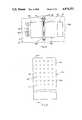
- FIG. 6is a front elevational view of a display board without display disks showing a rectangular array of light pipes which can be used with a matrix of rotatable display disks;
- FIG. 7is a vertical sectional view taken along line 7--7 of FIG. 6;
- FIG. 8is a rear elevational view of part of the light pipe assembly taken along line 8--8 of FIG. 7;
- FIG. 9is an enlarged fragmentary horizontal sectional view taken along 9--9 of FIG. 7;
- FIG. 10is fragmentary vertical sectional view taken along line 10--10 of FIG. 9;.
- FIG. 1a matrix display assembly generally designated as reference numeral 10 which has a vertical rectangular, nonreflective or black panel or backboard 12 on which is mounted a rectangular array of display disk assemblies 20.
- Each disk assembly or unit 20has a generally circular flat display disk 22.
- the disk assemblies 20are shown arrayed in seven horizontal rows and five vertical columns to total thirty-five units in the matrix display assembly 10.
- Each diskhas a colored light reflective display side 24, and a black or nonreflective side 26 and can be rotated to one of two positions so that either the colored side 24 faces forwardly and is exposed to ambient light in display position as indicated by display disks 22' or the nonreflective side 26 faces forwardly in reverse position as shown by display units 22".
- FIGS. 1, 2 and 3show that each of the disks 22 of the display unit 20 is rotatably supported by a rectangular U-shaped bracket 30 secured at its back to the nonreflective side 21 of the backboard or background board 12.
- the bracket 30has a pair of arms 32 apertured at their respective free ends to journal a rotatable shaft 34 which is secured to spaced leaves 36 at opposide ends of a bracket 38 secured to the black or non-reflecting side 26 of the disk 22.
- the outer end of the shaft 34carries a permanent magnet 40 having diametrically opposite spaced N and S poles. The magnet rotates adjacent to a pole piece 42 of an electromagnet 44 set in a hole 46 in the board 12.
- a cylindrical lamp post 50carrying a lamp 52.
- Wires 52'extend from the post 50 to a power supply circuit for energizing all the lamps 52 at the same time.
- Wires 54extend from the electromagnet 44 to energize the same selectively when it is desired to turn either the reflecting side 24 or the nonreflecting side 26 to the viewing position.
- the lamp 52is so located so that it is disposed in the line of sight of a tab 28 extending from the disk 22 when the disk 22 is turned to non-display position as shown by disks 22" in FIG. 1 and disk 22 in FIGS. 2 and 3.
- the tab 28then blocks the light from the lamp 52.
- the lamps 52are exposed because the tabs 28 are turned downwardly.
- the axes of rotation of the disks 22are disposed about 45° to the horizontal and vertical edges of the board 12. This orientation of shafts 34 makes the best use of spaces between the disk assemblies or units 20 and makes it possible to provide a projection lamp 52 adjacent to the periphery of each disk 22.
- the lamps 52are all disposed in a coplanar grid or array located behind the common place of the disks 22. By this arrangement the lamps 52 can project light beams forwardly of those disks 22 which are in display position and at the same time the light beams back light onto the displayed disks to outline the silhouettes of the lamps at night when ambient light is absent.
- the tabs 28will block and conceal the light of all lamps behind those disks 22 which are in a reversed, nonreflective, nondisplay position.
- FIG. 4shows a display disk 22 on an enlarged scale.
- the disk 22has a circular periphery 23 for about seven-eighths of its length or about 315°. At one point P the disk 22 is extended tangentially along Line L to meet line L' extending chordally from point P'. This defines a tab 28 having an apical angle of about 90° and mutually perpendicular edges 27,29. Edge 29 may be shorter than edge 27. The tab must be large enough to conceal the lamp 52 when the adjacent disk 22 is in reversed, nondisplay position.
- a plurality of disks 22can be turned to indicate a character.
- sixteen disks 22'are turned to display the letter "A" while remaining disks 22" and panel 12 furnish a black or nonreflecting background.
- the lamps 52may be turned on by a conventional light sensor or may be lit continuously, and under these circumstances, during daylight, the light from the lamps 52 are only faintly visible, because of the much more intense ambient light illuminating the display disks. In the absence of ambient light, such as at night, the lamps 52 become visible against the black background panel 12.
- the lamps 52define the same character previously displayed by reflecting light from adjacent disks 22' and by back lighting because they are located in a plane behind the plane of the disks 22.
- the inventionis not limited to the particular partially circular form of the disks 22.
- a display unit 20'having generally rectangular form of a display disk 22a having a bracket 38a extending transversely across a black nonreflecting side 26a.
- the disk 22ahas an end extension or tab 28a which overlaps a plurality of lamps 52a disposed in a row on respective posts 50a adjacent the disk 22a, when the disk is electromagnetically turned to the dotted line position shown in FIG. 5.
- greater back illumination and silhouettingis provided the disk 22a against black side 21' of a panel 12' and more intense forward projection of spot lighting beams is obtained than is possible with the single lamps 52 employed in the matrix 10.
- the disk assemblies or display units 20 and 20'can employ display disks of other shapes such as oval. In all cases the disks will have edge projections or tabs which conceal the spot lights in reversed position of the disks and which expose the spot lights in the display position of the disks 22a.
- FIGS. 6-10it is possible to employ a single lamp in a fiber optic array or grid as illustrated in FIGS. 6-10.
- this optical grid 70a multiplicity of light pipes 72 are disposed in a rectangular forward extending arrangement.
- Black background board 12ais similar to board 12 of FIG. 1, but is shown without display disks.
- a plurality of holes 48areceive straight end portions 74 of light conducting tubes or pipes 72.
- the free ends 75 of the tubes 72are disposed in coplanar array to serve as spot light sources.
- the parallel, horizontal end sections 74extend through the holes 48a to the back of the board. Then the pipes 72 bend vertically at sections 76 and horizontally again at end sections 78 to terminate at a vertical end sections 79. The end sections are gathered into a rectangular bundle held by endless rectangular band 80. The free ends 82 of the light pipes 72 are exposed to beams 83 from a lamp 84 in box 86 at the rear of a board 12a. By this arrangement there are provided thirty-five spot lights from the single illuminating lamp 84.
- the light pipes 72can be made of solid glass or plastic, or the individual light pipes can be a fiber glass optical conduit which has the dsired light conductivity.
- each of the lamp 52may be replaced by alight emitting diode. It is obvious that the display matrix can have more or less than thirty-five disk display units depending on specifications and requirements of any particular display application.
- the inventionmay be utilized with a display assembly where both sides of each of the display disks have the same color, i.e. black and in this instance, the visual display is only by projected light beams, from the light emitting from the light source of those display disks which are in the display position, with the display disks in the reverse position having their respective light sources blocked by their respective tabs.
Landscapes
- Physics & Mathematics (AREA)
- General Physics & Mathematics (AREA)
- Engineering & Computer Science (AREA)
- Theoretical Computer Science (AREA)
- Devices For Indicating Variable Information By Combining Individual Elements (AREA)
- Illuminated Signs And Luminous Advertising (AREA)
- Electrochromic Elements, Electrophoresis, Or Variable Reflection Or Absorption Elements (AREA)
Abstract
Description
Claims (17)
Priority Applications (9)
| Application Number | Priority Date | Filing Date | Title |
|---|---|---|---|
| US07/399,257US4974353A (en) | 1989-08-28 | 1989-08-28 | Matrix display assembly having multiple point lighting |
| GB9014876AGB2235560B (en) | 1989-08-28 | 1990-07-05 | Display unit with a rotatable panel and light source |
| US07/552,935US5022171A (en) | 1989-08-28 | 1990-07-16 | Matrix display assembly having multiple point lighting |
| CA002022354ACA2022354A1 (en) | 1989-08-28 | 1990-07-31 | Matrix display assembly having multiple point lighting |
| IT04823490AIT1244126B (en) | 1989-08-28 | 1990-08-22 | MATRIX-TYPE DISPLAY COMPLEX HAVING A PLURALITY OF LIGHT POINTS |
| AU61268/90AAU628276B2 (en) | 1989-08-28 | 1990-08-23 | Matrix display assembly having multiple point lighting |
| FR909010681AFR2651358B1 (en) | 1989-08-28 | 1990-08-27 | MATRIX GRAPHIC DISPLAY ASSEMBLY AND DISPLAY UNIT FOR SUCH AN ASSEMBLY. |
| DE4027204ADE4027204A1 (en) | 1989-08-28 | 1990-08-28 | Graphic character matrix display assembly - comprises series of flat display discs driven by electromagnet between display and reversed positions |
| JP2226418AJPH0396987A (en) | 1989-08-28 | 1990-08-28 | Matrix display apparatus with multispot illumination |
Applications Claiming Priority (1)
| Application Number | Priority Date | Filing Date | Title |
|---|---|---|---|
| US07/399,257US4974353A (en) | 1989-08-28 | 1989-08-28 | Matrix display assembly having multiple point lighting |
Related Child Applications (1)
| Application Number | Title | Priority Date | Filing Date |
|---|---|---|---|
| US07/552,935Continuation-In-PartUS5022171A (en) | 1989-08-28 | 1990-07-16 | Matrix display assembly having multiple point lighting |
Publications (1)
| Publication Number | Publication Date |
|---|---|
| US4974353Atrue US4974353A (en) | 1990-12-04 |
Family
ID=23578826
Family Applications (1)
| Application Number | Title | Priority Date | Filing Date |
|---|---|---|---|
| US07/399,257Expired - Fee RelatedUS4974353A (en) | 1989-08-28 | 1989-08-28 | Matrix display assembly having multiple point lighting |
Country Status (8)
| Country | Link |
|---|---|
| US (1) | US4974353A (en) |
| JP (1) | JPH0396987A (en) |
| AU (1) | AU628276B2 (en) |
| CA (1) | CA2022354A1 (en) |
| DE (1) | DE4027204A1 (en) |
| FR (1) | FR2651358B1 (en) |
| GB (1) | GB2235560B (en) |
| IT (1) | IT1244126B (en) |
Cited By (20)
| Publication number | Priority date | Publication date | Assignee | Title |
|---|---|---|---|---|
| US5022171A (en)* | 1989-08-28 | 1991-06-11 | The Staver Company Inc. | Matrix display assembly having multiple point lighting |
| US5050325A (en)* | 1990-05-14 | 1991-09-24 | Dayco Products Canada, Inc. | Display indicator and reed switch |
| US5237641A (en)* | 1992-03-23 | 1993-08-17 | Nioptics Corporation | Tapered multilayer luminaire devices |
| US5303322A (en)* | 1992-03-23 | 1994-04-12 | Nioptics Corporation | Tapered multilayer luminaire devices |
| US5528720A (en)* | 1992-03-23 | 1996-06-18 | Minnesota Mining And Manufacturing Co. | Tapered multilayer luminaire devices |
| EP0731435A1 (en) | 1995-03-08 | 1996-09-11 | Lite Vision Corporation | Magnetically operated display |
| FR2731828A1 (en)* | 1995-03-17 | 1996-09-20 | Jc Decaux | DISPLAY ELEMENT CELL WITH PIVOTING PAD FOR DOT MATRIX DISPLAY PANEL |
| USRE35357E (en)* | 1989-06-09 | 1996-10-22 | Mark Iv Industries, Ltd. | Display element with notched disk |
| US5600772A (en)* | 1994-08-17 | 1997-02-04 | Printronix, Inc. | Bit map character convertor using chain-codes for the character filling process |
| USD388123S (en)* | 1995-04-28 | 1997-12-23 | Copal Company Limited | Light-emitting diode indicator |
| FR2761189A1 (en)* | 1997-03-21 | 1998-09-25 | J C Decaux International | Point Matrix Display Panel Construction for Urban Electronic Newspapers |
| US5898418A (en)* | 1995-03-06 | 1999-04-27 | Kao; Pin-Chi | Magnetically operated display |
| US5909971A (en)* | 1996-03-01 | 1999-06-08 | Mark Iv Industries Limited | Display device with disk and LED |
| US6002829A (en)* | 1992-03-23 | 1999-12-14 | Minnesota Mining And Manufacturing Company | Luminaire device |
| US6115013A (en)* | 1995-12-04 | 2000-09-05 | American Electronic Sign Company | Display element having retroreflective surface |
| US6216370B1 (en)* | 1996-03-05 | 2001-04-17 | Mark Iv Industries Limited | Display array and device |
| DE19619814C2 (en)* | 1996-03-05 | 2002-05-08 | Mark Iv Ind Ltd | display |
| US6677922B1 (en) | 1995-12-04 | 2004-01-13 | 3M Innovative Properties Company | Display element having retroreflective surface |
| WO2011143164A1 (en)* | 2010-05-10 | 2011-11-17 | Leotek Electronics Corporation | Led luminaire light redirection shield |
| WO2011146746A1 (en)* | 2010-05-20 | 2011-11-24 | Shwed Roman Z | Reflective decoration assembly |
Families Citing this family (3)
| Publication number | Priority date | Publication date | Assignee | Title |
|---|---|---|---|---|
| US5793349A (en)* | 1992-03-20 | 1998-08-11 | Mark Iv Industries Limited | Electromagnetic shutter and cover |
| DE19614040A1 (en)* | 1996-04-10 | 1997-10-16 | Hans Damm | Illuminated display for destination boards in buses etc. |
| RU2123392C1 (en)* | 1996-08-02 | 1998-12-20 | Белгородская государственная технологическая академия строительных материалов | Centrifugal deflecting vortex separator |
Citations (7)
| Publication number | Priority date | Publication date | Assignee | Title |
|---|---|---|---|---|
| US1594703A (en)* | 1924-07-24 | 1926-08-03 | Bernard Van Leer | Advertising device |
| US4389804A (en)* | 1980-12-11 | 1983-06-28 | American Sign & Indicator Corporation | Matrix display |
| EP0109328A1 (en)* | 1982-11-05 | 1984-05-23 | Securite Et Signalisation | Luminous fibre matrix display |
| US4761905A (en)* | 1986-09-30 | 1988-08-09 | Black Fred M | Scanned electromechanical display |
| US4769638A (en)* | 1986-10-30 | 1988-09-06 | Woolfolk Robert L | Color graphics information display |
| US4800381A (en)* | 1985-01-22 | 1989-01-24 | Johannes Joseph | Electromagnetic indicator device |
| US4833806A (en)* | 1985-07-22 | 1989-05-30 | Societe D'etudes Pour Le Developpement | Display cell element for point matrix display panels |
Family Cites Families (4)
| Publication number | Priority date | Publication date | Assignee | Title |
|---|---|---|---|---|
| GB2045991B (en)* | 1979-04-06 | 1982-12-08 | Salam H P A | Matrix display device |
| EP0054336A1 (en)* | 1980-12-11 | 1982-06-23 | American Sign & Indicator Corporation | Matrix display |
| US4380479A (en)* | 1981-12-21 | 1983-04-19 | Gte Products Corporation | Foils of brittle alloys |
| DE3501912C2 (en)* | 1985-01-22 | 1987-04-16 | Friedrich Merk-Telefonbau GmbH, 8000 München | Electromagnetic display device |
- 1989
- 1989-08-28USUS07/399,257patent/US4974353A/ennot_activeExpired - Fee Related
- 1990
- 1990-07-05GBGB9014876Apatent/GB2235560B/ennot_activeExpired - Fee Related
- 1990-07-31CACA002022354Apatent/CA2022354A1/ennot_activeAbandoned
- 1990-08-22ITIT04823490Apatent/IT1244126B/enactiveIP Right Grant
- 1990-08-23AUAU61268/90Apatent/AU628276B2/ennot_activeCeased
- 1990-08-27FRFR909010681Apatent/FR2651358B1/ennot_activeExpired - Lifetime
- 1990-08-28DEDE4027204Apatent/DE4027204A1/ennot_activeWithdrawn
- 1990-08-28JPJP2226418Apatent/JPH0396987A/enactivePending
Patent Citations (7)
| Publication number | Priority date | Publication date | Assignee | Title |
|---|---|---|---|---|
| US1594703A (en)* | 1924-07-24 | 1926-08-03 | Bernard Van Leer | Advertising device |
| US4389804A (en)* | 1980-12-11 | 1983-06-28 | American Sign & Indicator Corporation | Matrix display |
| EP0109328A1 (en)* | 1982-11-05 | 1984-05-23 | Securite Et Signalisation | Luminous fibre matrix display |
| US4800381A (en)* | 1985-01-22 | 1989-01-24 | Johannes Joseph | Electromagnetic indicator device |
| US4833806A (en)* | 1985-07-22 | 1989-05-30 | Societe D'etudes Pour Le Developpement | Display cell element for point matrix display panels |
| US4761905A (en)* | 1986-09-30 | 1988-08-09 | Black Fred M | Scanned electromechanical display |
| US4769638A (en)* | 1986-10-30 | 1988-09-06 | Woolfolk Robert L | Color graphics information display |
Cited By (34)
| Publication number | Priority date | Publication date | Assignee | Title |
|---|---|---|---|---|
| USRE35357E (en)* | 1989-06-09 | 1996-10-22 | Mark Iv Industries, Ltd. | Display element with notched disk |
| US5022171A (en)* | 1989-08-28 | 1991-06-11 | The Staver Company Inc. | Matrix display assembly having multiple point lighting |
| US5050325A (en)* | 1990-05-14 | 1991-09-24 | Dayco Products Canada, Inc. | Display indicator and reed switch |
| US6993242B2 (en) | 1992-03-23 | 2006-01-31 | 3M Innovative Properties Company | Luminaire device |
| US7587117B2 (en) | 1992-03-23 | 2009-09-08 | 3M Innovative Properties Company | Luminaire device |
| US6335999B1 (en) | 1992-03-23 | 2002-01-01 | Minnesota Mining & Mfg. Co. | Multilayer luminaire device |
| US5237641A (en)* | 1992-03-23 | 1993-08-17 | Nioptics Corporation | Tapered multilayer luminaire devices |
| US7209628B2 (en) | 1992-03-23 | 2007-04-24 | 3M Innovative Properties Company | Luminaire device |
| US5303322A (en)* | 1992-03-23 | 1994-04-12 | Nioptics Corporation | Tapered multilayer luminaire devices |
| US5594830A (en)* | 1992-03-23 | 1997-01-14 | Minnesota Mining And Manufacturing Co. | Luminaire device |
| US5528720A (en)* | 1992-03-23 | 1996-06-18 | Minnesota Mining And Manufacturing Co. | Tapered multilayer luminaire devices |
| US7418188B2 (en) | 1992-03-23 | 2008-08-26 | 3M Innovative Properties Company | Luminaire device |
| US6671452B2 (en) | 1992-03-23 | 2003-12-30 | 3M Innovative Properties Company | Luminaire device |
| US6002829A (en)* | 1992-03-23 | 1999-12-14 | Minnesota Mining And Manufacturing Company | Luminaire device |
| US7424197B2 (en) | 1992-03-23 | 2008-09-09 | 3M Innovative Properties Company | Luminaire device |
| US6118418A (en)* | 1992-11-19 | 2000-09-12 | American Electronic Sign Company | Pixel for use in a visual matrix display |
| US5600772A (en)* | 1994-08-17 | 1997-02-04 | Printronix, Inc. | Bit map character convertor using chain-codes for the character filling process |
| US5898418A (en)* | 1995-03-06 | 1999-04-27 | Kao; Pin-Chi | Magnetically operated display |
| EP0731435A1 (en) | 1995-03-08 | 1996-09-11 | Lite Vision Corporation | Magnetically operated display |
| WO1996029690A1 (en)* | 1995-03-17 | 1996-09-26 | J.C. Decaux | Basic display cell with a pivotable flap for a dot-matrix display |
| FR2731828A1 (en)* | 1995-03-17 | 1996-09-20 | Jc Decaux | DISPLAY ELEMENT CELL WITH PIVOTING PAD FOR DOT MATRIX DISPLAY PANEL |
| USD388123S (en)* | 1995-04-28 | 1997-12-23 | Copal Company Limited | Light-emitting diode indicator |
| US6137460A (en)* | 1995-12-04 | 2000-10-24 | American Electronic Sign Company | Display element having retroreflective surface |
| US6677922B1 (en) | 1995-12-04 | 2004-01-13 | 3M Innovative Properties Company | Display element having retroreflective surface |
| US6115013A (en)* | 1995-12-04 | 2000-09-05 | American Electronic Sign Company | Display element having retroreflective surface |
| US5909971A (en)* | 1996-03-01 | 1999-06-08 | Mark Iv Industries Limited | Display device with disk and LED |
| DE19619814C2 (en)* | 1996-03-05 | 2002-05-08 | Mark Iv Ind Ltd | display |
| US6216370B1 (en)* | 1996-03-05 | 2001-04-17 | Mark Iv Industries Limited | Display array and device |
| FR2761189A1 (en)* | 1997-03-21 | 1998-09-25 | J C Decaux International | Point Matrix Display Panel Construction for Urban Electronic Newspapers |
| WO2011143164A1 (en)* | 2010-05-10 | 2011-11-17 | Leotek Electronics Corporation | Led luminaire light redirection shield |
| CN102884372A (en)* | 2010-05-10 | 2013-01-16 | 光林电子股份有限公司 | Light-emitting diode lighting fixtures light redirection shielding |
| US8511865B2 (en) | 2010-05-10 | 2013-08-20 | Leotek Electronics Corporation | LED luminaire light redirection shield |
| WO2011146746A1 (en)* | 2010-05-20 | 2011-11-24 | Shwed Roman Z | Reflective decoration assembly |
| CN102971778A (en)* | 2010-05-20 | 2013-03-13 | 光热制造公司 | Reflective decoration assembly |
Also Published As
| Publication number | Publication date |
|---|---|
| CA2022354A1 (en) | 1991-03-01 |
| IT9048234A0 (en) | 1990-08-22 |
| IT9048234A1 (en) | 1992-02-22 |
| AU628276B2 (en) | 1992-09-10 |
| AU6126890A (en) | 1991-03-14 |
| GB9014876D0 (en) | 1990-08-22 |
| GB2235560B (en) | 1993-10-27 |
| DE4027204A1 (en) | 1991-03-07 |
| JPH0396987A (en) | 1991-04-22 |
| IT1244126B (en) | 1994-07-08 |
| FR2651358B1 (en) | 1992-07-03 |
| GB2235560A (en) | 1991-03-06 |
| FR2651358A1 (en) | 1991-03-01 |
Similar Documents
| Publication | Publication Date | Title |
|---|---|---|
| US4974353A (en) | Matrix display assembly having multiple point lighting | |
| US5022171A (en) | Matrix display assembly having multiple point lighting | |
| US4922384A (en) | Illuminated display with half-silvered mirrors and discrete refractor plates | |
| US3135063A (en) | Rotary sign | |
| US4765080A (en) | Illuminated information display apparatus | |
| US4724629A (en) | Illuminated display board | |
| USRE35357E (en) | Display element with notched disk | |
| US4136474A (en) | Illuminated overhead advertising display | |
| JPH10301509A (en) | Writable display sign | |
| EP0737348A1 (en) | Display device | |
| US5237766A (en) | Illuminated sign | |
| US4034494A (en) | Holiday light | |
| DE69428607D1 (en) | REFLECTIVE DISPLAY LABEL | |
| US3611603A (en) | Illuminated display device | |
| US4914427A (en) | Matrix display system and method | |
| US4761004A (en) | Infinity mirror display | |
| US5600909A (en) | Illuminated changeable message display | |
| US5136492A (en) | Light display | |
| WO2005059443A1 (en) | Display arrangement | |
| US6137460A (en) | Display element having retroreflective surface | |
| US3629655A (en) | Luminous display device | |
| US1857882A (en) | Changeable sign front | |
| CA2171054C (en) | Display device and array | |
| US2199308A (en) | Sign apparatus | |
| KR100541229B1 (en) | Light emitting device |
Legal Events
| Date | Code | Title | Description |
|---|---|---|---|
| AS | Assignment | Owner name:LAKE TECHNOLOGIES INC., FLORIDA Free format text:ASSIGNMENT OF ASSIGNORS INTEREST.;ASSIGNOR:NORFOLK, ROY;REEL/FRAME:005203/0242 Effective date:19890811 Owner name:STAVER COMPANY INC., THE, NEW YORK Free format text:ASSIGNMENT OF ASSIGNORS INTEREST.;ASSIGNOR:NORFOLK, ROY;REEL/FRAME:005203/0242 Effective date:19890811 | |
| AS | Assignment | Owner name:STAVER COMPANY INC., THE, A CORP. OF NEW YORK, NEW Free format text:ASSIGNMENT OF ASSIGNORS INTEREST.;ASSIGNOR:LAKE TECHNOLOGIES INC.;REEL/FRAME:005280/0840 Effective date:19900312 | |
| FEPP | Fee payment procedure | Free format text:PAYOR NUMBER ASSIGNED (ORIGINAL EVENT CODE: ASPN); ENTITY STATUS OF PATENT OWNER: SMALL ENTITY | |
| AS | Assignment | Owner name:FLEET BANK, NEW YORK Free format text:ASSIGNMENT OF ASSIGNORS INTEREST;ASSIGNOR:STAVER COMPANY INCORPORATED, THE;REEL/FRAME:006801/0359 Effective date:19931130 | |
| FPAY | Fee payment | Year of fee payment:4 | |
| FPAY | Fee payment | Year of fee payment:8 | |
| AS | Assignment | Owner name:FOOTHILL CAPITAL CORPORATION, VIRGINIA Free format text:SECURITY INTEREST;ASSIGNOR:STAVER COMPANY, INCORPORATED, THE;REEL/FRAME:009614/0675 Effective date:19981027 | |
| AS | Assignment | Owner name:COLORADO TIME SYSTEMS, LLC, COLORADO Free format text:ASSIGNMENT OF ASSIGNORS INTEREST;ASSIGNOR:STAVER COMPANY INCORPORATED, THE;REEL/FRAME:010018/0228 Effective date:19990528 | |
| REMI | Maintenance fee reminder mailed | ||
| LAPS | Lapse for failure to pay maintenance fees | ||
| STCH | Information on status: patent discontinuation | Free format text:PATENT EXPIRED DUE TO NONPAYMENT OF MAINTENANCE FEES UNDER 37 CFR 1.362 | |
| FP | Lapsed due to failure to pay maintenance fee | Effective date:20021204 |